EP4571010A1 - A cover assembly and a method for interconnecting cover members - Google Patents
A cover assembly and a method for interconnecting cover members Download PDFInfo
- Publication number
- EP4571010A1 EP4571010A1 EP24204765.2A EP24204765A EP4571010A1 EP 4571010 A1 EP4571010 A1 EP 4571010A1 EP 24204765 A EP24204765 A EP 24204765A EP 4571010 A1 EP4571010 A1 EP 4571010A1
- Authority
- EP
- European Patent Office
- Prior art keywords
- edge
- cover member
- edge flange
- section
- Prior art date
- Legal status (The legal status is an assumption and is not a legal conclusion. Google has not performed a legal analysis and makes no representation as to the accuracy of the status listed.)
- Pending
Links
Images




Classifications
-
- E—FIXED CONSTRUCTIONS
- E04—BUILDING
- E04D—ROOF COVERINGS; SKY-LIGHTS; GUTTERS; ROOF-WORKING TOOLS
- E04D13/00—Special arrangements or devices in connection with roof coverings; Protection against birds; Roof drainage ; Sky-lights
- E04D13/14—Junctions of roof sheathings to chimneys or other parts extending above the roof
- E04D13/147—Junctions of roof sheathings to chimneys or other parts extending above the roof specially adapted for inclined roofs
- E04D13/1473—Junctions of roof sheathings to chimneys or other parts extending above the roof specially adapted for inclined roofs specially adapted to the cross-section of the parts extending above the roof
- E04D13/1475—Junctions of roof sheathings to chimneys or other parts extending above the roof specially adapted for inclined roofs specially adapted to the cross-section of the parts extending above the roof wherein the parts extending above the roof have a generally rectangular cross-section
-
- E—FIXED CONSTRUCTIONS
- E04—BUILDING
- E04D—ROOF COVERINGS; SKY-LIGHTS; GUTTERS; ROOF-WORKING TOOLS
- E04D13/00—Special arrangements or devices in connection with roof coverings; Protection against birds; Roof drainage ; Sky-lights
- E04D13/03—Sky-lights; Domes; Ventilating sky-lights
- E04D13/0305—Supports or connecting means for sky-lights of flat or domed shape
- E04D13/031—Supports or connecting means for sky-lights of flat or domed shape characterised by a frame for connection to an inclined roof
Definitions
- the present invention relates to a cover assembly for at least one roof penetrating structure, such as a roof window, comprising: a first cover member comprising a pocket section forming a pocket extending along a pocket plane and having a pocket opening and a pocket end opposite the opening, where a pocket depth is measured along the pocket plane from the pocket opening to the pocket end, and where a pocket height is measured perpendicular to the pocket plane; and a second cover member comprising an edge flange extending in an edge flange plane and having a bent edge bent along a bend line, said bend line forming a free edge of the edge flange, where an edge flange height is measured perpendicular to the flange plane, and where an edge flange width is measured in parallel to the flange plane, perpendicular to and away from the bend line, said edge flange width being equal to or larger than the pocket depth; where each of the first cover member and the second cover member has an interior side configured for facing a roof window or a roof structure in
- cover assembly and the method are not limited to use with roof windows but may also be used with other types of roof penetrating structures, such as solar collectors or solar panels.
- Roof windows mounted in roof structure are usually provided with weather-proofing comprising a plurality of members, including flashing members covering the joint between the roof window and the roof structure, covering members covering the joint between flashing members and a frame of the roof window, and possibly also cladding members covering an exterior side of a roof window.
- “Cover member” is here used as a common name for all of these members.
- an edge flange of one cover member When interconnecting two cover members made from sheet material, such as sheet metal, an edge flange of one cover member may be inserted in a pocket form by a pocket section on another cover member, or the pocket section on one cover member may be hooked onto an edge flange of another cover member.
- These methods provide for a simple and reliable interconnection, which may be fixated by securing the two cover members to one or more other elements, such as to the frame of a roof window. Such a fixation may allow the edge flange and the pocket section to still move slightly in relation to each other, thereby for example compensating for thermal expansion.
- the interconnection of an edge flange and a pocket section may also allow the cover members to be installed in different mutual positions, for example allowing them to be used in different installation situations, where a roof window is mounted deeper or higher in the roof structure or where distance between the frame of the roof window and the roofing material is different.
- the size of the overlap between the edge flange and the pocket section will simply be adjusted to compensate for different depth or distance.
- edge flange in the pocket In some installation situations, a full insertion of the edge flange in the pocket is necessary, for example to be able to fit a gutter-shaped cover assembly between roof windows mounted side-by-side. Failure to fulfil this requirement may lead to insufficient weather-proofing or to the cover assembly being discarded. Furthermore, with the increasing focus on reducing environmental impacts, the possibility for disassembly to facilitate recycling and/or allow repair rather than replacement becomes ever more important.
- a cover assembly of the kind mentioned in the introduction which is furthermore characterised in that the bent edge of the edge flange comprises a compacted section closest to the bend line and a lip section extending from the compacted section at an angle to the flange plane, that the pocket height is larger than the edge flange height at the compacted section and smaller than the maximum edge flange height at the lip section.
- the pocket end of a cover member As the pocket section of a cover member is often formed by folding, roll-forming or the like, the pocket end will often have a rounded shape, and the pocket height will therefore decrease at the innermost end of the pocket. It has been found that this in combination with the abovementioned desire for keeping the pocket height low is contributing to the difficulty sometimes experienced when attempting to achieve a full insertion of the edge flange in the pocket. The fact that some cover members are made with relatively high tolerances may contribute to this problem. If the pocket is made by simple folding along one single bend line, not attempting to achieve a rounded pocket end, these effects may be even more pronounced. With the compacted section the edge flange height closest to the free edge is reduced compared to with a bent edge without a compacted section, increasing the likelihood that the bent edge can be fully inserted in the pocket.
- the compacted section may further entail a smaller radius of curvature at the free edge, which may reduce the risk of the edge flange getting stuck, for example caused by capillary suction between the pocket end and the free edge.
- the maximum edge flange height at the lip section may be found at an edge of the lip section remote from the compacted section but may also be located further towards the compacted section.
- the pocket height is at least twice the edge flange height at the compacted section, and/or that a radius of curvature of the pocket end is at least twice a radius of curvature of the free edge.
- the material of the edge flange may be deformed into a sharp edge at the free edge.
- the height of the pocket may be reduced at the pocket opening to reduce the risk of water or dirt entering the pocket in the mounted state. Such a reduced height is not to be taken into consideration when determining the sizes of the compacted section and the lip section relative to the pocket height.
- the compacted section may for example be made by compression of a section of the bent edge, i.e. first folding an outer edge of the edge flange and subsequently compressing the section closest to the free edge.
- the compacted section and the lip section may be made by two subsequent folding operations, where the outer edge of the edge flange is first bent so that it extends substantially in parallel to the edge flange plane and where the lip section is then created by bending a section of the outer edge away from the edge flange plane.
- the lip section will typically extend at an angle of 5-30 degrees from the edge flange plane. An angle of less than 15 degrees is presently envisaged.
- the size of the compacted section and the lip section may vary, depending amongst others on the overall dimensions of the cover member, the material used, the thickness of the material, and the dimensions of the pocket. It is presently considered advantageous that the compacted section has a width of at least 3 mm, preferably at least 5 mm, measured in parallel with the edge flange plane and in a direction away from the bend line, and that the lip section extends a further 7 mm, preferably at least 10 mm, away from the bend line.
- the lip section will engage with an inner surface of the pocket pressing the edge flange against an opposite inner surface of the pocket seen in the height direction.
- a tight contact between the edge flange and an inner surface of the pocket may contribute to the weather-proofing properties of the cover assembly, especially if the lip section projects at the interior side of the second cover member and presses the edge flange against the inner surface of the pocket located at the exterior side of the first cover member.
- the lip section may be made from an elastic material.
- the sheet metals, such as aluminium, typically used for cover members will have sufficient elasticity to achieve this effect, meaning that the entire second cover member may be made from the same material.
- the size and elasticity of the lip section should be such that frictional resistance between the lip section and the inner surface of the pocket during insertion of the edge flange in the pocket does not prevent or undue hinder the mounting of the cover assembly.
- the first cover member further comprises an engagement section extending ways from the pocket opening along the pocket plane in a direction away from the pocket end.
- the engagement section may for example be a bent edge being configured for engagement with the bent edge of the second cover member. This may prevent unintentional separation of the first cover member and the second cover member and/or contribute to the weather-proofing properties of the cover assembly. If the bent edge of the second cover member projects from interior side, the bent edge of the first cover member should then project from the exterior side.
- At least the edge flange is preferably made from a sheet material, such as sheet metal, which is commonly used for cover members, aluminium, copper, and stainless steel being most common materials. Other material, such as polymers, may, however, also be used, and both cover members may be covered wholly or partially with other materials, such as a lacquer.
- a friction reducing coating is provided in the pocket and/or on the edge flange to facilitate mounting of the cover assembly.
- a cover member made entirely from a polymer will likely be made by extrusion or moulding, and it is to be understood that references made to "bent edge”, “bent along”, “bend line” etc. is to be understood as a bent shape, not necessarily as a shape that needs to be achieved by a bending process.
- a method for mounting cover members of a cover assembly at at least one roof penetrating structure, such as a roof window comprising:
- the fact that the compacted section constitutes the leading edge increases the likelihood that a full insertion will be possible and pressure of the lip section against the inner surface of the pocket may contribute to an optimal positioning of the edge flange relative to the pocket.
- first cover member and the second cover member may be interconnected by insertion of the edge flange in the pocket before arranging them at the roof window/roof structure.
- the method comprises the following sequence of steps:
- This embodiment is particularly well suited for a gutter-shaped cover assembly used between roof windows.
- the cover assembly When arranged in the narrow configuration the cover assembly will be easy to arrange between the roof windows and once in place it can be expanded to fit the space available between the roof windows.
- the retraction of the edge flange is continued until both cover members are in contact with a roof penetrating structure, such as a roof window, thereby allowing the size of the cover assembly to be adapted to the size of the space between the roof windows/roof penetrating structures. This may especially be advantageous when replacing old cover assemblies or roof window installations with new ones as the dimension of older installations do not always match today's standard. If the cover assembly is not fully expanded it may also be possible to compensate for roof windows not being completely aligned, by retracting the edge flange further at one end than at the other end of the cover assembly.
- the retraction is continued until the bent edge on the second cover member engages with a bent edge on the first cover member.
- the provision of such bent edges engaging with each other may not only prevent unintended disassembly but may also contribute to ensure the weather-proofing properties of the cover assembly to ensuring the necessary overlap between the edge flange and the first cover member.
- the cover assembly is used in a position where the insertion direction is perpendicular to the plane of roof structure, for example where the first cover member is a covering member and the second cover member a flashing member, the method may comprise the following sequence of steps:
- this may allow to compensate for difference in the installation depth of the roof window in the roof structure and/or for variations in installation depth.
- cover assembly is used as a flashing member, allowing the relative position of the first cover member and the second cover member to be adjusted to match a distance between a roof window and a roofing material surrounding the roof window.
- This may for example be relevant when the cover assembly is a side flashing member and the roofing material is tiles, as it may allow an adaptation of the extend of the cover assembly to the undulating shape of the tiles.
- a prior art cover assembly 100 is shown. It comprises a first cover member 10 and a second cover member 20 each having two legs 101, 102, 201, 202 extending perpendicular to each other so that the cover assembly has a gutter-shape.
- This cover assembly 100 may be used in place of any of the gutter-shaped flashing members 13, 16 used between roof penetrating structures, here in the form of roof window frames 1 in Fig. 2 .
- First legs 101, 201 of the cover members 10, 20 will then be extending along outer sides of the roof window frames, while the second legs 102, 202 forming the bottom of the gutter will extend between the roof window frames in parallel with the plane of the roof structure (not shown).
- each of the first cover member 10 and the second cover member 20 has an interior side configured for facing a roof window or a roof structure in a mounted state of the cover assembly and an exterior side configured for facing towards an exterior in the mounted state.
- the first cover member 10 and the second cover member 20 is in the embodiments shown each formed as a generally longitudinally extending profile element, having a length direction which in the installation situations to be described in the following is parallel to a slope direction D of the roof structure, and extending into the plane of the drawing in Fig. 1 .
- a first cover member 10 of the type shown in Fig. 1 is shown in more detail in Fig. 3 . It comprises pocket section 104 closest to the first leg 101 and an engagement section 105 at the end of the second leg 102, furthest from the first leg.
- the pocket section 104 comprises an interior part 1021 and an exterior part 2022 forming a slit-shaped pocket 106 extending along a pocket plane P.
- the pocket has a pocket opening 1061 and a pocket end 1062 opposite the pocket opening and two inner surfaces 1063, 1064 extending between the pocket opening and the pocket end, said inner surfaces being formed by the interior part 1021 and the exterior part 2022, respectively.
- a pocket depth PD is measured along the pocket plane from the pocket opening to the pocket end, and a pocket height PH is measured perpendicular to the pocket depth.
- the engagement section 105 extends ways from the pocket opening 1061 along the pocket plane P in a direction away from the pocket end 1062, having a width SW.
- the engagement section comprises a bent edge 1051 bent along a bend line 1052 forming a free edge of the second leg 104.
- This bent edge is configured for engaging with a bent edge 2051 of an edge flange 202 of the second cover member 20, said edge flange constituting the second leg of the second cover member as will be described in further detail below and defining an edge flange extending in an edge flange plane F.
- the edge flange 202 of the second cover member 20 has been inserted in the pocket 106 of the first cover member 10 to approximate half of the pocket depth, and the entire bent edge 2051 of the second cover member is consequently located in the pocket.
- the bent edges 1051, 2051 which are shown in their undeformed states in Fig. 1 , will be pressed down towards the inner surface 1063 and the edge flange 202, respectively.
- the bent edge 1051 of the first cover member will thus be pressing against the interior side of the edge flange 202, and the bent edge 2051 of the second cover member will be pressing against the inner surface 1063 of the pocket 106, both thus pressing the edge flange 202 towards the inner surface 1064 of the pocket 106.
- a second cover member 20 for a cover assembly according to the invention is shown in Fig. 4 . It differs from the second cover member in Fig. 1 in the design of the bent edge 2051, which is shown in detail in Fig. 5 .
- the bent edge 2051 here comprises a compacted section 2053 closest to the bend line 2052 and a lip section 2054 extending from the compacted section at an angle A to the flange plane F.
- the edge flange height EHC at the compacted section 2053 measured perpendicular to the flange plane F is smaller than the pocket height PH, and the maximum edge flange height EHL at the lip section 2054 is larger than the pocket height PH.
- the pocket end 1062 is indicated by a broken line embracing the end of the compacted section 2053 in Fig. 5 , showing the pocket height as being approximately twice the edge flange height EH at the compacted section.
- the relative heights are also seen in Fig. 6 and Fig. 7 , where the edge flange 202 of the second cover member in Fig. 4 is shown inserted in the pocket 106 of the first cover member shown in Fig. 3 .
- An edge flange width EW of the edge flange 202 is measured in parallel to the flange plane F, perpendicular to and away from the bend line 2052. This edge flange width EW is equal to or larger than the pocket depth PD of the first cover member 10.
- the width CW of the compacted section 2053 is smaller than the width LW of the lip section, thus constituting less than half of the total width BW of the bent edge.
- These dimensions may vary, but the width of the compacted section must be big enough to allow complete insertion and preferably also easy separation of the second cover member 20 in/from the pocket 106 of the first cover member 10.
- width LW of the lip section should be big enough to ensure that the maximum edge flange height EHL at the lip section is larger than the pocket height PH.
- the widths of the compacted section and the lip section will thus depend on the angle A of the lip section and the shape and dimensions of the pocket 106, also taking account of the tolerances allowed in the production of the cover members.
- the material used for making the second cover member 20 has a sheet thickness of 0.06 mm, edge flange height EHC at the compacted section is approximately 1.5 mm, the maximum edge flange height EHL is approximately 3 mm, the width CW of the compacted section is approximately 8 mm, and the width LW of the lip section is approximately 13 mm.
- a cover member assembly 100 comprising the cover members 10, 20 in Fig. 3 and Fig. 4 is shown in a narrow configuration and in an expanded configuration.
- edge flange 202 of the second cover member 20 has been inserted fully into the pocket 106 of the first cover member 10, so that the free edge of the edge flange at the bend line 2052 is at the pocket end 1062.
- the edge flange width EW is larger than the pocket depth PD.
- the radius of curvature of the pocket end is here approximately twice the radius of curvature at the free edge of the edge flange.
- the lip section 2054 of the edge flange is shown as projecting through the interior part 1021 of the pocket section 104, but this is only to illustrate that the maximum edge flange height is larger than the pocket height as described above. In reality the lip section will be pressed back by the contact with the inner surface 1063 of the pocket. Such a deformation is shown on the bent edge 1051 of the engagement section 105, which presses against the interior side of the edge flange 202.
- the second cover member 20 has been pulled back from the first cover member 10 as indicated by the arrow VII in Fig. 6 .
- the width BW of the bent edge 2051 of the second cover member is larger the width SW of the engagement section 105. This means that movement perpendicular to the flange plane F will also be prevented, thus preventing unintentional disassembly on the cover assembly 100.
- the overlap between the edge flange 202 and the exterior part 1022 of the pocket section 104 has a width corresponding approximately to the width CW of the compacted section of the bent edge 2051 of the second cover member 20, but other relative dimensions are possible.
- each of the cover members 10, 20 are here made by folding from a single piece of sheet metal, such as aluminium or copper, but could also be made from a polymer and would then likely be made by extrusion or moulding. Extrusion or moulding could also be used for making a cover member from metal. If making the first cover member 10 by extrusion or moulding, the exterior part 1022 of the pocket section 104, which comprises two layers of material in the embodiment shown in Fig. 3 , will then only comprises a single layer of material.
- FIG. 8 Alternative embodiments of the cover assembly are shown in Fig. 8 and Fig. 9 .
- the first leg 201 of the second cover member 20 is considerably shorter than the first leg 101 of the first cover member 10.
- This cover assembly is well suited for use as a side flashing member as those having reference number 11 in Fig. 2 or as a bottom flashing member as those having reference number 6 in Fig. 2 . If the shorter first leg was instead found on the first cover member 10, it would also be well suited for use as a top flashing member as those having reference number 2 in Fig. 2 .
- first legs 101', 201' of both the first cover member 10 and the second cover member 20 are embodied as the second leg 202 of the second cover member shown in Fig. 1 , but could also be embodied as the second leg of the second cover member shown in Fig. 4 .
- These first legs 101', 201' are interconnected with additional cover members 10', 10", each of which are embodied as the first cover member 10 in Fig. 3 .
- These four cover members 10, 20, 10', 10" form a gutter-shaped cover assembly with variable dimensions both in a width direct and in a height direction.
- This gutter-shaped cover assembly is well suited for use as a middle flashing member as those having reference numbers 13 and 16 in Fig.
- the gutter-shaped cover assembly can be arranged between two roof window frames in a narrow configuration and then expanded until being in contact with both roof window frames.
- the cover assembly can be arranged with the horizontal parts of the additional cover members riding on top of the two roof window frames and then expanded until the second legs 102, 202 of the first cover member 10 and the second cover member 20 reaches the roof structure between the two roof window frames.
- a further embodiment of a cover assembly 100 is shown arranged between two roof window frames 1 in Fig. 10 .
- This cover assembly differs from those in Fig. 7 and Fig. 9 in that bent edge 1051 of the first cover member 10 is shorter and in that the first legs 101, 201 are provided with bent edges 1011, 2011.
- the shorter bent edge 1051 of the first cover member 10 may reduce the pressure exerted on the second leg 202 of the second cover member 20, which may facilitate interconnection of the first and second cover members 10, 20.
- the bent edges 1011, 2011 of the first legs 101, 201 are bent outwards, so that they are projecting from the exterior sides of the first legs, and they engage with frame covering members 30 provided on the roof window frames 1.
- Each frame covering member has a bent edge 3051, which is bent inwards, onto an interior side of the frame covering member, and which abut on the plane sections of the first legs. This means that the bent edges 1011, 2011 and the bent edges 3051 will hook into each other if the cover assembly 100 is lowered from the position shown in Fig. 10 , thus limiting the relative movement.
- a chamber 40 is formed between the bent edges, which may contribute to the weather-proofing by serving as a labyrinth seal and a pressure relief chamber, hindering air from being pressed up underneath the frame covering member.
- the bent edges 1011, 2011 of the first legs 101, 201 are embodied with a compacted section and a lip section in the same way as the bent edge 2051 of the second cover member in Fig. 4 .
- This may facilitate movement of the cover assembly 100 relative to the roof window frame members 100 and the frame covering members 30, but bent edges 1011, 2011 could also be simple bends on the engagement section 105 of the first cover member in Fig. 3 .
- Figs. 11 to 20B further aspects of the invention will be described in some detail with reference to a roof structure 7 comprising four roof penetrating structures 1a, 1b, 1c, 1d. Elements having the same or analogous function as in the embodiments described in the above carry the same reference numerals.
- the two lowermost roof penetrating structures 1a, 1b as seen in the slope direction D are each provided with a bottom flashing member 6a, 6b forming part of a flashing assembly.
- FIG. 13A and 13B Further components of the flashing assembly comprise a set of parts to form a two-part flashing member 100 of the type described with reference to Figs 1-10 .
- two different second cover members 20 and 20' is selected as indicated in Figs. 13A and 13B .
- a first cover member 10 is provided, shown in Fig. 14 .
- the first cover member 10 is formed with a first leg portion and a second leg portion forming a pocket between them (not indicated in detail) substantially as shown in Figs. 3 and 8 .
- the first cover member 10 comprises a first leg 101 (cf. Fig. 19 ).
- the flashing assembly is provided with holding means.
- the holding means may be temporary to provide a provisional hold in an installation step, or form part of the permanent structure securing the flashing assembly to the roof penetrating structure(s) or the roof structure.
- the holding means ensure that cover members to be positioned between neighbouring roof penetrating structures with the length direction of the flashing member in parallel with the slope direction.
- the holding means may be positive or non-positive.
- positive engagement German: formschlüssig
- positive engagement is to be interpreted as encompassing mechanical coupling of two otherwise separate components such that the design and geometry of the components prevent the coupling from being released unintentionally by forces to which the components are subjected during use, including in particular such mechanical couplings in which mutually complementary shapes of the respective components fit together in the engaged position, and in which intentional movement of at least one of the components out of the engaged position is required, typically involving at least partial movement of part(s) of one or both components in a direction at an angle to the intended movement.
- positive engagement is to be understood as any form of form-locking coupling in which the shapes or geometrical forms of two components interlock with each other in such a way that they create an engagement preventing disengagement until intentional release is carried out by an active or conscious action by a user.
- non-positive engagement German: kraftschlüssig
- non-positive engagement means include frictional connections, magnetic connections, “soft” snap connections, etc. in which the engagement between the components is enabled by means of forces mainly in the tangential direction rather than the normal direction.
- the holding means may be placed on any cover member of the flashing assembly.
- the holding means may comprise a substantially planar lug extending in a plane substantially parallel to any plane spanned by portions of a cover member.
- the planar lug may be formed to extend in the plane spanned by the height direction H and slope direction D of a cover member.
- Such planar lug or lugs may be formed to protrude from the cover member.
- each planar lug may be chosen arbitrarily to conform to manufacturing, transportation, or installation requirements.
- Each planar lug may be foldable about a folding line substantially parallel to the height direction H or slope direction D.
- a substantially planar lug 614 is formed on the bottom flashing member 6a of the first roof penetrating structure 1a.
- the planar lug 614 here has a trapezoidal shape and protrudes from a perpendicular flange of the bottom flashing member 6a to extend in the plane spanned by the height direction H and the slope direction D.
- the planar lug 614 is configured to be foldable about a folding line substantially parallel to the slope direction D to abut the first leg 101 of the first cover member 10 of the flashing member 100 in a mounted condition of the flashing assembly.
- the trapezoidal lug 614 assumes a folded-back position substantially in parallel with its original plane and acts as a force-locking engagement means in hindering the flashing member 100 from sliding along the sloping roof by frictional forces.
- the engagement may be reinforced by clamping the trapezoidal lug 614 manually, possibly by means of a suitable tool.
- a substantially planar lug 1015 is formed on the first leg 101 of the first cover member 10 of the flashing member 100.
- the planar lug 1015 has a rectangular shape and protrudes from the first leg 101 to extend in the planned spanned by the height direction H and the slope direction D.
- the planar lug 1015 is configured to be foldable about a folding line substantially parallel to the height direction H to a position at right angles with its original plane to be brought into abutment with a portion of the first roof penetrating structure 1a, typically at a corner of the stationary frame of a roof window, or at a portion of any insulation frame mounted to the frame.
- the rectangular lug 1015 provides a form-locking engagement with the first roof penetrating structure 1a, thus improving the retention of the flashing member 100 even further.
Landscapes
- Engineering & Computer Science (AREA)
- Architecture (AREA)
- Civil Engineering (AREA)
- Structural Engineering (AREA)
- Roof Covering Using Slabs Or Stiff Sheets (AREA)
Abstract
Description
- The present invention relates to a cover assembly for at least one roof penetrating structure, such as a roof window, comprising: a first cover member comprising a pocket section forming a pocket extending along a pocket plane and having a pocket opening and a pocket end opposite the opening, where a pocket depth is measured along the pocket plane from the pocket opening to the pocket end, and where a pocket height is measured perpendicular to the pocket plane; and a second cover member comprising an edge flange extending in an edge flange plane and having a bent edge bent along a bend line, said bend line forming a free edge of the edge flange, where an edge flange height is measured perpendicular to the flange plane, and where an edge flange width is measured in parallel to the flange plane, perpendicular to and away from the bend line, said edge flange width being equal to or larger than the pocket depth; where each of the first cover member and the second cover member has an interior side configured for facing a roof window or a roof structure in a mounted state of the cover assembly and an exterior side configured for facing towards an exterior in the mounted state. The invention further relates to a method for interconnecting cover members.
- While reference will be made primarily to roof windows mounted in roof structures, it is to be understood that the cover assembly and the method are not limited to use with roof windows but may also be used with other types of roof penetrating structures, such as solar collectors or solar panels.
- Roof windows mounted in roof structure are usually provided with weather-proofing comprising a plurality of members, including flashing members covering the joint between the roof window and the roof structure, covering members covering the joint between flashing members and a frame of the roof window, and possibly also cladding members covering an exterior side of a roof window. "Cover member" is here used as a common name for all of these members.
- When interconnecting two cover members made from sheet material, such as sheet metal, an edge flange of one cover member may be inserted in a pocket form by a pocket section on another cover member, or the pocket section on one cover member may be hooked onto an edge flange of another cover member. These methods provide for a simple and reliable interconnection, which may be fixated by securing the two cover members to one or more other elements, such as to the frame of a roof window. Such a fixation may allow the edge flange and the pocket section to still move slightly in relation to each other, thereby for example compensating for thermal expansion. If the pocket formed by the pocket section is deeper than the minimum overlap required between the cover members to provide a sufficient weather-proofing, the interconnection of an edge flange and a pocket section may also allow the cover members to be installed in different mutual positions, for example allowing them to be used in different installation situations, where a roof window is mounted deeper or higher in the roof structure or where distance between the frame of the roof window and the roofing material is different. The size of the overlap between the edge flange and the pocket section will simply be adjusted to compensate for different depth or distance.
- While the interconnection of such cover members is usually quite easy, experience has shown that it is not always possible to insert the edge flange fully into the pocket of the pocket section, especially in a slit-shaped pocket where the height of the pocket is small as is often desired for design reasons or to make room for other items. Furthermore, it may be difficult to separate the cover members from each other, particularly when the edge flange is provided with a bent edge to ensure a tight contact between the two cover members as described in the applicant's co-pending patent application
DK202370172 - In some installation situations, a full insertion of the edge flange in the pocket is necessary, for example to be able to fit a gutter-shaped cover assembly between roof windows mounted side-by-side. Failure to fulfil this requirement may lead to insufficient weather-proofing or to the cover assembly being discarded. Furthermore, with the increasing focus on reducing environmental impacts, the possibility for disassembly to facilitate recycling and/or allow repair rather than replacement becomes ever more important.
- With this background, it is an object of the invention to provide a cover assembly and a method for interconnecting cover members allowing the full range of the overlap between the edge flange and the pocket section to be exploited. Further it is desired to provide a cover assembly and a method for interconnecting cover members allowing easy disassembly.
- These and further objects are achieved with a cover assembly of the kind mentioned in the introduction which is furthermore characterised in that the bent edge of the edge flange comprises a compacted section closest to the bend line and a lip section extending from the compacted section at an angle to the flange plane, that the pocket height is larger than the edge flange height at the compacted section and smaller than the maximum edge flange height at the lip section.
- As the pocket section of a cover member is often formed by folding, roll-forming or the like, the pocket end will often have a rounded shape, and the pocket height will therefore decrease at the innermost end of the pocket. It has been found that this in combination with the abovementioned desire for keeping the pocket height low is contributing to the difficulty sometimes experienced when attempting to achieve a full insertion of the edge flange in the pocket. The fact that some cover members are made with relatively high tolerances may contribute to this problem. If the pocket is made by simple folding along one single bend line, not attempting to achieve a rounded pocket end, these effects may be even more pronounced. With the compacted section the edge flange height closest to the free edge is reduced compared to with a bent edge without a compacted section, increasing the likelihood that the bent edge can be fully inserted in the pocket.
- The compacted section may further entail a smaller radius of curvature at the free edge, which may reduce the risk of the edge flange getting stuck, for example caused by capillary suction between the pocket end and the free edge.
- The maximum edge flange height at the lip section may be found at an edge of the lip section remote from the compacted section but may also be located further towards the compacted section.
- It is presently considered advantageous that the pocket height is at least twice the edge flange height at the compacted section, and/or that a radius of curvature of the pocket end is at least twice a radius of curvature of the free edge. To reduce the radius of curvature of the free edge, the material of the edge flange may be deformed into a sharp edge at the free edge.
- The height of the pocket may be reduced at the pocket opening to reduce the risk of water or dirt entering the pocket in the mounted state. Such a reduced height is not to be taken into consideration when determining the sizes of the compacted section and the lip section relative to the pocket height.
- The compacted section may for example be made by compression of a section of the bent edge, i.e. first folding an outer edge of the edge flange and subsequently compressing the section closest to the free edge. Alternatively, the compacted section and the lip section may be made by two subsequent folding operations, where the outer edge of the edge flange is first bent so that it extends substantially in parallel to the edge flange plane and where the lip section is then created by bending a section of the outer edge away from the edge flange plane. The lip section will typically extend at an angle of 5-30 degrees from the edge flange plane. An angle of less than 15 degrees is presently envisaged.
- The size of the compacted section and the lip section may vary, depending amongst others on the overall dimensions of the cover member, the material used, the thickness of the material, and the dimensions of the pocket. It is presently considered advantageous that the compacted section has a width of at least 3 mm, preferably at least 5 mm, measured in parallel with the edge flange plane and in a direction away from the bend line, and that the lip section extends a further 7 mm, preferably at least 10 mm, away from the bend line.
- As the maximum edge flange height at the lip section is larger than the pocket height, the lip section will engage with an inner surface of the pocket pressing the edge flange against an opposite inner surface of the pocket seen in the height direction. A tight contact between the edge flange and an inner surface of the pocket may contribute to the weather-proofing properties of the cover assembly, especially if the lip section projects at the interior side of the second cover member and presses the edge flange against the inner surface of the pocket located at the exterior side of the first cover member. To further facilitate a tight contact between the edge flange and the inner surface of the pocket, the lip section may be made from an elastic material. The sheet metals, such as aluminium, typically used for cover members will have sufficient elasticity to achieve this effect, meaning that the entire second cover member may be made from the same material.
- Notwithstanding the above, the size and elasticity of the lip section should be such that frictional resistance between the lip section and the inner surface of the pocket during insertion of the edge flange in the pocket does not prevent or undue hinder the mounting of the cover assembly.
- In one embodiment, the first cover member further comprises an engagement section extending ways from the pocket opening along the pocket plane in a direction away from the pocket end. The engagement section may for example be a bent edge being configured for engagement with the bent edge of the second cover member. This may prevent unintentional separation of the first cover member and the second cover member and/or contribute to the weather-proofing properties of the cover assembly. If the bent edge of the second cover member projects from interior side, the bent edge of the first cover member should then project from the exterior side.
- At least the edge flange is preferably made from a sheet material, such as sheet metal, which is commonly used for cover members, aluminium, copper, and stainless steel being most common materials. Other material, such as polymers, may, however, also be used, and both cover members may be covered wholly or partially with other materials, such as a lacquer. In one embodiment a friction reducing coating is provided in the pocket and/or on the edge flange to facilitate mounting of the cover assembly.
- A cover member made entirely from a polymer will likely be made by extrusion or moulding, and it is to be understood that references made to "bent edge", "bent along", "bend line" etc. is to be understood as a bent shape, not necessarily as a shape that needs to be achieved by a bending process.
- In a second aspect of the invention the abovementioned objects are achieved with a method for mounting cover members of a cover assembly at at least one roof penetrating structure, such as a roof window, comprising:
- Providing a first cover member comprising a pocket section forming a pocket having a pocket opening and a pocket end opposite the opening, where a pocket depth is measured from the pocket opening to the pocket end, and where a pocket height is measured perpendicular to the pocket depth,
- Providing a second cover member comprising an edge flange extending in an edge flange plane and having a bent edge bent along a bend line, said bend line forming a free edge of the edge flange, where an edge flange height is measured perpendicular to the flange plane, and where an edge flange width measured in parallel to the flange plane, perpendicular to and away from the bend line is equal to or larger than the pocket depth,
- Arranging each of the first cover member and the second cover member with an interior side facing a roof window or a roof structure and an exterior side facing towards an exterior, and
- Inserting the edge flange of the second cover member in the pocket of the first cover member by relative displacement of first cover member and the second cover member along an insertion direction extending in parallel with the edge flange plane, where a compacted section of a bent edge of the edge flange constitutes the leading edge of the edge flange during insertion into the pocket, and where a lip section extending from the compacted section at an angle to the flange plane presses against an inner surface of the pocket during the insertion and in the mounted state of the cover assembly.
- As described above, the fact that the compacted section constitutes the leading edge increases the likelihood that a full insertion will be possible and pressure of the lip section against the inner surface of the pocket may contribute to an optimal positioning of the edge flange relative to the pocket.
- The method step mentioned above do not necessarily have to be performed in the order in which they are mentioned. As an example, the first cover member and the second cover member may be interconnected by insertion of the edge flange in the pocket before arranging them at the roof window/roof structure.
- Unless otherwise stated embodiments and advantages described with reference to one aspect of the invention also applies to the other and to avoid undue repetition, most will only be described with reference to one aspect.
- In one embodiment the method
comprises the following sequence of steps: - Arranging the cover assembly in a narrow configuration by inserting the edge flange fully into the pocket,
- Arranging the cover assembly at a roof penetrating structure, such as a roof window, and
- Bringing the cover assembly into an expanded configuration by retracting the edge flange partially from the pocket.
- This embodiment is particularly well suited for a gutter-shaped cover assembly used between roof windows. When arranged in the narrow configuration the cover assembly will be easy to arrange between the roof windows and once in place it can be expanded to fit the space available between the roof windows.
- In one embodiment, the retraction of the edge flange is continued until both cover members are in contact with a roof penetrating structure, such as a roof window, thereby allowing the size of the cover assembly to be adapted to the size of the space between the roof windows/roof penetrating structures. This may especially be advantageous when replacing old cover assemblies or roof window installations with new ones as the dimension of older installations do not always match today's standard. If the cover assembly is not fully expanded it may also be possible to compensate for roof windows not being completely aligned, by retracting the edge flange further at one end than at the other end of the cover assembly.
- In another embodiment the retraction is continued until the bent edge on the second cover member engages with a bent edge on the first cover member. The provision of such bent edges engaging with each other may not only prevent unintended disassembly but may also contribute to ensure the weather-proofing properties of the cover assembly to ensuring the necessary overlap between the edge flange and the first cover member.
- If the cover assembly is used in a position where the insertion direction is perpendicular to the plane of roof structure, for example where the first cover member is a covering member and the second cover member a flashing member, the method may comprise the following sequence of steps:
- Arranging the cover assembly in an expanded configuration where the edge flange is inserted only partially into the pocket,
- Arranging the cover assembly at a roof penetrating structure, such as a roof window, and
- Inserting the edge flange further into the pocket until both cover members are in contact with a roof window or roof structure.
- As described with reference to the gutter-shaped cover assembly above, this may allow to compensate for difference in the installation depth of the roof window in the roof structure and/or for variations in installation depth.
- A similar effect may be achieved where the cover assembly is used as a flashing member, allowing the relative position of the first cover member and the second cover member to be adjusted to match a distance between a roof window and a roofing material surrounding the roof window. This may for example be relevant when the cover assembly is a side flashing member and the roofing material is tiles, as it may allow an adaptation of the extend of the cover assembly to the undulating shape of the tiles.
- In the following description embodiments of the invention will be described with reference to the schematic drawings, in which
-
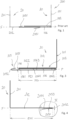
Fig. 1 is a cross-sectional view of a prior art cover assembly, -
Fig. 2 is a perspective view of a prior art cover assembly for a group of four roof windows, -
Fig. 3 is a cross-sectional view of a first cover member, -
Fig. 4 is a cross-sectional view of a second cover member, -
Fig. 5 is an enlarged view of the detail marked V inFig. 4 , -
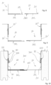
Fig. 6 is a cross-sectional view of a cover member assembly comprising the cover members inFig. 3 and Fig. 4 in a narrow configuration, -
Fig. 7 is a cross-sectional view of the cover assembly inFig. 6 in an expanded configuration, -
Fig. 8 is a cross-sectional view of a first cover member and a second cover member, -
Fig. 9 is a cross-sectional view of two interconnectable cover assemblies, -
Fig. 10 is a cross-sectional view of a cover assembly arranged between two roof window frames and engaging with frame covering members, -
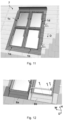
Fig. 11 is a perspective view of a roof structure with four roof penetrating structures, during a step of installation, -
Fig. 12 is a partial perspective views of the lower two roof penetrating roof structures ofFig. 9 , during a further step of installation, -
Figs. 13A and 13B are perspective views of a second cover member of a flashing member in alternative embodiments, -
Fig. 14 is a perspective views of a first cover member and a second cover member of a two-part flashing member during assembly, -
Fig. 15 is a perspective view of the two-part flashing member ofFig. 14 in an assembled condition, -
Fig. 16 is a perspective view of the roof structure ofFig. 11 during engagement of the two-part flashing member ofFig. 15 in an installation step, -
Figs. 17A and 17B are partial perspective views showing respective positions of the first cover member and the second cover member during adjustment of the mutual position in an installation step, -
Fig. 18 is a partial perspective view of the roof structure ofFig. 16 in a further installation step, -
Fig. 19 is a partial side sectional view showing the roof structure ofFig. 16 in a still further installation step, and -
Figs. 20A and 20B are partial perspective views of a flashing member in yet further installation step. - In the following the same reference numbers will be used for items having the same function even though they may not be structurally identical. It is to be understood that a description given with reference to one such item also applies to the other(s), and that only difference between the items will be described.
- Referring initially to
Fig. 1 , a priorart cover assembly 100 is shown. It comprises afirst cover member 10 and asecond cover member 20 each having twolegs cover assembly 100 may be used in place of any of the gutter-shapedflashing members roof window frames 1 inFig. 2 .First legs cover members second legs Fig. 1 constitutes an exterior side of the cover assembly facing an exterior in the mounted state, and the side facing downwards inFig. 1 constitutes an interior side facing the interior of the building in which the roof windows are installed. Likewise, each of thefirst cover member 10 and thesecond cover member 20 has an interior side configured for facing a roof window or a roof structure in a mounted state of the cover assembly and an exterior side configured for facing towards an exterior in the mounted state. - The
first cover member 10 and thesecond cover member 20 is in the embodiments shown each formed as a generally longitudinally extending profile element, having a length direction which in the installation situations to be described in the following is parallel to a slope direction D of the roof structure, and extending into the plane of the drawing inFig. 1 . - A
first cover member 10 of the type shown inFig. 1 is shown in more detail inFig. 3 . It comprisespocket section 104 closest to thefirst leg 101 and anengagement section 105 at the end of thesecond leg 102, furthest from the first leg. - The
pocket section 104 comprises aninterior part 1021 and an exterior part 2022 forming a slit-shapedpocket 106 extending along a pocket plane P. The pocket has a pocket opening 1061 and apocket end 1062 opposite the pocket opening and twoinner surfaces 1063, 1064 extending between the pocket opening and the pocket end, said inner surfaces being formed by theinterior part 1021 and the exterior part 2022, respectively. A pocket depth PD is measured along the pocket plane from the pocket opening to the pocket end, and a pocket height PH is measured perpendicular to the pocket depth. - The
engagement section 105 extends ways from the pocket opening 1061 along the pocket plane P in a direction away from thepocket end 1062, having a width SW. The engagement section comprises abent edge 1051 bent along abend line 1052 forming a free edge of thesecond leg 104. This bent edge is configured for engaging with abent edge 2051 of anedge flange 202 of thesecond cover member 20, said edge flange constituting the second leg of the second cover member as will be described in further detail below and defining an edge flange extending in an edge flange plane F. In the assembled state of the cover assembly shown inFig. 1 , theedge flange 202 of thesecond cover member 20 has been inserted in thepocket 106 of thefirst cover member 10 to approximate half of the pocket depth, and the entirebent edge 2051 of the second cover member is consequently located in the pocket. As a consequence of this insertion, thebent edges Fig. 1 , will be pressed down towards theinner surface 1063 and theedge flange 202, respectively. In the assembled state thebent edge 1051 of the first cover member will thus be pressing against the interior side of theedge flange 202, and thebent edge 2051 of the second cover member will be pressing against theinner surface 1063 of thepocket 106, both thus pressing theedge flange 202 towards the inner surface 1064 of thepocket 106. - A
second cover member 20 for a cover assembly according to the invention is shown inFig. 4 . It differs from the second cover member inFig. 1 in the design of thebent edge 2051, which is shown in detail inFig. 5 . Thebent edge 2051 here comprises a compactedsection 2053 closest to thebend line 2052 and alip section 2054 extending from the compacted section at an angle A to the flange plane F. The edge flange height EHC at the compactedsection 2053 measured perpendicular to the flange plane F is smaller than the pocket height PH, and the maximum edge flange height EHL at thelip section 2054 is larger than the pocket height PH. Thepocket end 1062 is indicated by a broken line embracing the end of the compactedsection 2053 inFig. 5 , showing the pocket height as being approximately twice the edge flange height EH at the compacted section. The relative heights are also seen inFig. 6 and Fig. 7 , where theedge flange 202 of the second cover member inFig. 4 is shown inserted in thepocket 106 of the first cover member shown inFig. 3 . - In the embodiment show there is a sharp bent between the
compacted section 2053 and alip section 2054. It is to be understood that this is not necessarily the case and that the transition between compacted section and the lip section may be more gradual. - An edge flange width EW of the
edge flange 202 is measured in parallel to the flange plane F, perpendicular to and away from thebend line 2052. This edge flange width EW is equal to or larger than the pocket depth PD of thefirst cover member 10. - In the embodiment shown in
Fig. 5 , the width CW of the compactedsection 2053 is smaller than the width LW of the lip section, thus constituting less than half of the total width BW of the bent edge. These dimensions may vary, but the width of the compacted section must be big enough to allow complete insertion and preferably also easy separation of thesecond cover member 20 in/from thepocket 106 of thefirst cover member 10. Likewise, width LW of the lip section should be big enough to ensure that the maximum edge flange height EHL at the lip section is larger than the pocket height PH. The widths of the compacted section and the lip section will thus depend on the angle A of the lip section and the shape and dimensions of thepocket 106, also taking account of the tolerances allowed in the production of the cover members. - In the embodiment shown in
Fig. 5 , the material used for making thesecond cover member 20 has a sheet thickness of 0.06 mm, edge flange height EHC at the compacted section is approximately 1.5 mm, the maximum edge flange height EHL is approximately 3 mm, the width CW of the compacted section is approximately 8 mm, and the width LW of the lip section is approximately 13 mm. - Turning now to
Fig. 6 and Fig. 7 , acover member assembly 100 comprising thecover members Fig. 3 and Fig. 4 is shown in a narrow configuration and in an expanded configuration. - In the narrow configuration in
Fig. 6 theedge flange 202 of thesecond cover member 20 has been inserted fully into thepocket 106 of thefirst cover member 10, so that the free edge of the edge flange at thebend line 2052 is at thepocket end 1062. To allow this, the edge flange width EW is larger than the pocket depth PD. The radius of curvature of the pocket end is here approximately twice the radius of curvature at the free edge of the edge flange. - The
lip section 2054 of the edge flange is shown as projecting through theinterior part 1021 of thepocket section 104, but this is only to illustrate that the maximum edge flange height is larger than the pocket height as described above. In reality the lip section will be pressed back by the contact with theinner surface 1063 of the pocket. Such a deformation is shown on thebent edge 1051 of theengagement section 105, which presses against the interior side of theedge flange 202. - In the expanded configuration in
Fig. 7 , thesecond cover member 20 has been pulled back from thefirst cover member 10 as indicated by the arrow VII inFig. 6 . This has resulted in thelip section 2054 of thebent edge 2051 of the second cover member hooking into thebent edge 1051 of theengagement section 105 of the first cover member, prevent further relative movement of the cover members along the flange plane F. In the embodiment shown, the width BW of thebent edge 2051 of the second cover member is larger the width SW of theengagement section 105. This means that movement perpendicular to the flange plane F will also be prevented, thus preventing unintentional disassembly on thecover assembly 100. In the embodiment shown the overlap between theedge flange 202 and theexterior part 1022 of thepocket section 104 has a width corresponding approximately to the width CW of the compacted section of thebent edge 2051 of thesecond cover member 20, but other relative dimensions are possible. - In the embodiments shown, each of the
cover members first cover member 10 by extrusion or moulding, theexterior part 1022 of thepocket section 104, which comprises two layers of material in the embodiment shown inFig. 3 , will then only comprises a single layer of material. - Alternative embodiments of the cover assembly are shown in
Fig. 8 and Fig. 9 . - In
Fig. 8 thefirst leg 201 of thesecond cover member 20 is considerably shorter than thefirst leg 101 of thefirst cover member 10. This cover assembly is well suited for use as a side flashing member as those having reference number 11 inFig. 2 or as a bottom flashing member as those havingreference number 6 inFig. 2 . If the shorter first leg was instead found on thefirst cover member 10, it would also be well suited for use as a top flashing member as those havingreference number 2 inFig. 2 . - In
Fig. 9 the first legs 101', 201' of both thefirst cover member 10 and thesecond cover member 20 are embodied as thesecond leg 202 of the second cover member shown inFig. 1 , but could also be embodied as the second leg of the second cover member shown inFig. 4 . These first legs 101', 201' are interconnected withadditional cover members 10', 10", each of which are embodied as thefirst cover member 10 inFig. 3 . Together these fourcover members reference numbers Fig. 2 and will be able to compensate both for differences in the distance between theroof window frames 1 and for difference in the installation depth of the roof window frames. The gutter-shaped cover assembly can be arranged between two roof window frames in a narrow configuration and then expanded until being in contact with both roof window frames. Likewise, the cover assembly can be arranged with the horizontal parts of the additional cover members riding on top of the two roof window frames and then expanded until thesecond legs first cover member 10 and thesecond cover member 20 reaches the roof structure between the two roof window frames. - A further embodiment of a
cover assembly 100 is shown arranged between tworoof window frames 1 inFig. 10 . This cover assembly differs from those inFig. 7 andFig. 9 in thatbent edge 1051 of thefirst cover member 10 is shorter and in that thefirst legs bent edges - The shorter
bent edge 1051 of thefirst cover member 10 may reduce the pressure exerted on thesecond leg 202 of thesecond cover member 20, which may facilitate interconnection of the first andsecond cover members - The
bent edges first legs frame covering members 30 provided on the roof window frames 1. Each frame covering member has abent edge 3051, which is bent inwards, onto an interior side of the frame covering member, and which abut on the plane sections of the first legs. This means that thebent edges bent edges 3051 will hook into each other if thecover assembly 100 is lowered from the position shown inFig. 10 , thus limiting the relative movement. Furthermore, when arranged as inFig. 10 , achamber 40 is formed between the bent edges, which may contribute to the weather-proofing by serving as a labyrinth seal and a pressure relief chamber, hindering air from being pressed up underneath the frame covering member. - In the embodiment in
Fig. 10 , thebent edges first legs bent edge 2051 of the second cover member inFig. 4 . This may facilitate movement of thecover assembly 100 relative to the roofwindow frame members 100 and theframe covering members 30, butbent edges engagement section 105 of the first cover member inFig. 3 . - Turning now to
Figs. 11 to 20B , further aspects of the invention will be described in some detail with reference to aroof structure 7 comprising fourroof penetrating structures - Below, reference will be made to a two-part flashing member/flashing assembly, but it is to be understood that it could also be another type of cover assembly.
- The two lowermost
roof penetrating structures bottom flashing member - Further components of the flashing assembly comprise a set of parts to form a two-
part flashing member 100 of the type described with reference toFigs 1-10 . Depending on the spacing between pairs of neighbouringroof penetrating structures second cover members 20 and 20' is selected as indicated inFigs. 13A and 13B . - A
first cover member 10 is provided, shown inFig. 14 . Thefirst cover member 10 is formed with a first leg portion and a second leg portion forming a pocket between them (not indicated in detail) substantially as shown inFigs. 3 and8 . Furthermore, thefirst cover member 10 comprises a first leg 101 (cf.Fig. 19 ). - In order to improve the installation conditions even further, the flashing assembly is provided with holding means. The holding means may be temporary to provide a provisional hold in an installation step, or form part of the permanent structure securing the flashing assembly to the roof penetrating structure(s) or the roof structure.
- The holding means ensure that cover members to be positioned between neighbouring roof penetrating structures with the length direction of the flashing member in parallel with the slope direction.
- The holding means may be positive or non-positive.
- The term "positive engagement" (German: formschlüssig) is to be interpreted as encompassing mechanical coupling of two otherwise separate components such that the design and geometry of the components prevent the coupling from being released unintentionally by forces to which the components are subjected during use, including in particular such mechanical couplings in which mutually complementary shapes of the respective components fit together in the engaged position, and in which intentional movement of at least one of the components out of the engaged position is required, typically involving at least partial movement of part(s) of one or both components in a direction at an angle to the intended movement. In other words, the term positive engagement is to be understood as any form of form-locking coupling in which the shapes or geometrical forms of two components interlock with each other in such a way that they create an engagement preventing disengagement until intentional release is carried out by an active or conscious action by a user.
- As opposed hereto, "non-positive engagement" (German: kraftschlüssig) involves such engagement which only requires a force in the direction of intended movement to obtain release. A non-exhaustive list of examples of non-positive engagement means include frictional connections, magnetic connections, "soft" snap connections, etc. in which the engagement between the components is enabled by means of forces mainly in the tangential direction rather than the normal direction.
- The holding means may be placed on any cover member of the flashing assembly.
- The holding means may comprise a substantially planar lug extending in a plane substantially parallel to any plane spanned by portions of a cover member. The planar lug may be formed to extend in the plane spanned by the height direction H and slope direction D of a cover member.
- Such planar lug or lugs may be formed to protrude from the cover member.
- The shape of each planar lug may be chosen arbitrarily to conform to manufacturing, transportation, or installation requirements.
- Each planar lug may be foldable about a folding line substantially parallel to the height direction H or slope direction D.
- In the embodiment shown in more detail in
Figs. 18 and 19 , a substantiallyplanar lug 614 is formed on thebottom flashing member 6a of the firstroof penetrating structure 1a. - The
planar lug 614 here has a trapezoidal shape and protrudes from a perpendicular flange of thebottom flashing member 6a to extend in the plane spanned by the height direction H and the slope direction D. - The
planar lug 614 is configured to be foldable about a folding line substantially parallel to the slope direction D to abut thefirst leg 101 of thefirst cover member 10 of the flashingmember 100 in a mounted condition of the flashing assembly. - Thus, in the mounted condition the
trapezoidal lug 614 assumes a folded-back position substantially in parallel with its original plane and acts as a force-locking engagement means in hindering the flashingmember 100 from sliding along the sloping roof by frictional forces. - The engagement may be reinforced by clamping the
trapezoidal lug 614 manually, possibly by means of a suitable tool. - In the embodiment shown in more detail in
Figs. 20A and 20B , a substantiallyplanar lug 1015 is formed on thefirst leg 101 of thefirst cover member 10 of the flashingmember 100. - The
planar lug 1015 has a rectangular shape and protrudes from thefirst leg 101 to extend in the planned spanned by the height direction H and the slope direction D. - The
planar lug 1015 is configured to be foldable about a folding line substantially parallel to the height direction H to a position at right angles with its original plane to be brought into abutment with a portion of the firstroof penetrating structure 1a, typically at a corner of the stationary frame of a roof window, or at a portion of any insulation frame mounted to the frame. In this way, therectangular lug 1015 provides a form-locking engagement with the firstroof penetrating structure 1a, thus improving the retention of the flashingmember 100 even further. -
- 1
- roof window frame
- 2
- Top flashing member
- 6
- Bottom flashing member
- 6a
- Bottom flashing member
- 6b
- Bottom flashing member
- 614
- trapezoid lug
- 10
- First cover member
- 101
- First leg
- 1011
- bent edge
- 1015
- rectangular lug
- 102
- Second leg
- 1021
- Interior part
- 1022
- Exterior part
- 104
- Pocket section
- 105
- Engagement section
- 1051
- Bent edge
- 1052
- Bend line
- 106
- 1061
- Pocket opening
- 1062
- Pocket end
- 1063
- Inner surface
- 1064
- Inner surface
- 10'
- Additional cover member
- 10"
- Additional cover member
- 100
- Cover assembly
- 11
- Side flashing member
- 13
- Gutter-shaped flashing member
- 16
- Gutter-shaped flashing member
- 20
- Second cover member
- 20'
- second cover member (alternative embodiment)
- 201
- First leg
- 2011
- bent edge
- 202
- Second leg / edge flange
- 2051
- Bent edge
- 2052
- Bend line
- 2053
- Compacted section
- 2054
- Lip section
- 30
- Frame covering member
- 3051
- Bent edge
- 7
- Roof structure
- A
- Angle of lip section
- BW
- Width of bent edge
- CW
- Width of compacted section
- D
- slope direction
- EH
- Edge flange height
- EHC
- Edge flange height at compacted section
- EHL
- Maximum edge flange height
- EW
- Edge flange width
- F
- Edge flange plane
- H
- height direction
- LW
- Lip width
- P
- Pocket plane
- PD
- Pocket depth
- PH
- Pocket height
- SW
- Engagement section width
- W
- width direction
Claims (13)
- A cover assembly for at least one roof penetrating structure, such as a roof window, comprising:a first cover member comprising a pocket section forming a pocket extending along a pocket plane and having a pocket opening and a pocket end opposite the opening, where a pocket depth is measured along the pocket plane from the pocket opening to the pocket end, and where a pocket height is measured perpendicular to the pocket plane, anda second cover member comprising an edge flange extending in an edge flange plane and having a bent edge bent along a bend line, said bend line forming a free edge of the edge flange, where an edge flange height is measured perpendicular to the flange plane, and where an edge flange width is measured in parallel to the flange plane, perpendicular to and away from the bend line, said edge flange width being equal to or larger than the pocket depth,where each of the first cover member and the second cover member has an interior side configured for facing a roof window or a roof structure in a mounted state of the cover assembly and an exterior side configured for facing towards an exterior in the mounted state,characterised in thatthe bent edge of the edge flange comprises a compacted section closest to the bend line and a lip section extending from the compacted section at an angle to the flange plane, that the pocket height is larger than the edge flange height at the compacted section and smaller than the maximum edge flange height at the lip section.
- A cover assembly according to claim 1, wherein the maximum edge flange height at the lip section is found at an edge side of the lip section remote from the compacted section.
- A cover assembly according to claim 1 or 2, where the pocket height is at least twice the edge flange height at the compacted section, and/or where a radius of curvature of the pocket end is at least twice a radius of curvature of the free edge.
- A cover assembly according to one or more of the preceding claims, wherein the lip section projects at the interior side of the second cover member.
- A cover assembly according to one or more of the preceding claims, where the compacted section is made by compression of a section of the bent edge.
- A cover assembly according to one or more of the preceding claims, where at least the lip section is made from an elastic material, such as aluminium.
- A cover assembly according to one or more of the preceding claims, where the first cover member further comprises an engagement section extending ways from the pocket opening along the pocket plane in a direction away from the pocket end.
- A cover assembly according to one or more of the preceding claims, where at least the edge flange is made from a sheet material, such as sheet metal.
- A cover assembly according to one or more of the preceding claims, where at least one cover member is made by folding of a sheet material.
- A method for mounting cover members of a cover assembly at least one roof penetrating structure, such as a roof window, comprising:Providing a first cover member comprising a pocket section forming a pocket having a pocket opening and a pocket end opposite the opening, where a pocket depth is measured from the pocket opening to the pocket end, and where a pocket height is measured perpendicular to the pocket depth,Providing a second cover member comprising an edge flange extending in an edge flange plane and having a bent edge bent along a bend line, said bend line forming a free edge of the edge flange, where an edge flange height is measured perpendicular to the flange plane, and where an edge flange width is measured in parallel to the flange plane, perpendicular to and away from the bend line, said edge flange width being equal to or larger than the pocket depth,Arranging each of the first cover member and the second cover member with an interior side facing a roof window or a roof structure and an exterior side facing towards an exterior, andInserting the edge flange of the second cover member in the pocket of the first cover member by relative displacement of first cover member and the second cover member along an insertion direction extending in parallel with the edge flange plane, where a compacted section of a bent edge of the edge flange constitutes the leading edge of the edge flange during insertion into the pocket, and where a lip section extending from the compacted section at an angle to the flange plane presses against an inner surface of the pocket during the insertion and in the mounted state of the cover assembly.
- A method according to claim 10, comprising the following sequence of steps:Arranging the cover assembly in a narrow configuration by inserting the edge flange fully into the pocket,Arranging the cover assembly at a roof penetrating structure, such as a roof window, andBringing the cover assembly into an expanded configuration by retracting the edge flange partially from the pocket.
- A method according to claim 11, where the retraction is continued until both cover members are in contact with a roof penetrating structure, such as a roof window or until the bent edge on the second cover member engages with a bent edge on the first cover member.
- A method according to claim 10, comprising the following sequence of steps:Arranging the cover assembly in an expanded configuration where the edge flange is inserted only partially into the pocket,Arranging the cover assembly at a roof penetrating structure, such as a roof window, andInserting the edge flange further into the pocket until both cover members are in contact with a roof window or roof structure.
Priority Applications (3)
| Application Number | Priority Date | Filing Date | Title |
|---|---|---|---|
| US18/972,343 US20250188746A1 (en) | 2023-12-11 | 2024-12-06 | Cover assembly and a method for interconnecting cover members |
| CN202423029919.1U CN223706896U (en) | 2023-12-11 | 2024-12-09 | Cover component |
| EP25207005.7A EP4722465A2 (en) | 2024-10-04 | 2025-10-06 | A kit of covering members, a method of manufacturing a kit of covering members, and use of the kit of covering members |
Applications Claiming Priority (1)
| Application Number | Priority Date | Filing Date | Title |
|---|---|---|---|
| DKPA202370609 | 2023-12-11 |
Publications (1)
| Publication Number | Publication Date |
|---|---|
| EP4571010A1 true EP4571010A1 (en) | 2025-06-18 |
Family
ID=93014016
Family Applications (1)
| Application Number | Title | Priority Date | Filing Date |
|---|---|---|---|
| EP24204765.2A Pending EP4571010A1 (en) | 2023-12-11 | 2024-10-04 | A cover assembly and a method for interconnecting cover members |
Country Status (3)
| Country | Link |
|---|---|
| US (1) | US20250188746A1 (en) |
| EP (1) | EP4571010A1 (en) |
| CN (1) | CN223706896U (en) |
Citations (2)
| Publication number | Priority date | Publication date | Assignee | Title |
|---|---|---|---|---|
| US5522189A (en) * | 1994-04-18 | 1996-06-04 | V. Kann Rasmussen Industri A/S | Flashing for roof elements |
| PL70359Y1 (en) * | 2016-11-30 | 2018-11-30 | Fakro Pp Spolka Z Ograniczona Odpowiedzialnoscia | Roof window flashings that seals coupling of a roof window with photovoltaic panel |
-
2024
- 2024-10-04 EP EP24204765.2A patent/EP4571010A1/en active Pending
- 2024-12-06 US US18/972,343 patent/US20250188746A1/en active Pending
- 2024-12-09 CN CN202423029919.1U patent/CN223706896U/en active Active
Patent Citations (2)
| Publication number | Priority date | Publication date | Assignee | Title |
|---|---|---|---|---|
| US5522189A (en) * | 1994-04-18 | 1996-06-04 | V. Kann Rasmussen Industri A/S | Flashing for roof elements |
| PL70359Y1 (en) * | 2016-11-30 | 2018-11-30 | Fakro Pp Spolka Z Ograniczona Odpowiedzialnoscia | Roof window flashings that seals coupling of a roof window with photovoltaic panel |
Also Published As
| Publication number | Publication date |
|---|---|
| US20250188746A1 (en) | 2025-06-12 |
| CN223706896U (en) | 2025-12-23 |
Similar Documents
| Publication | Publication Date | Title |
|---|---|---|
| US5363624A (en) | Roofing and siding system | |
| EP2420634A1 (en) | Connecting member | |
| US20120174519A1 (en) | Covering made from mechanically interconnectable panels | |
| JP7254189B2 (en) | FLASHING ASSEMBLY FOR ROOF PENETRATION STRUCTURE AND METHOD OF MANUFACTURING FLASHING ASSEMBLY | |
| JP7276906B2 (en) | Horizontal roof structure | |
| EP4442924A1 (en) | A flashing assembly for use between two roof windows mounted in an inclined roof structure, a group of roof windows mounted using such a flashing assembly, and a method for mounting a flashing assembly between two roof windows | |
| US20250188746A1 (en) | Cover assembly and a method for interconnecting cover members | |
| EP4571008A1 (en) | Flashing member, roof structure and method of adapting a flashing member for covering a gap | |
| EP3243976B1 (en) | Panel splice connector for linear ceiling panels | |
| EP3862501B1 (en) | A secondary profile connector for a suspended ceiling system | |
| EP3683377B1 (en) | Insulating frame and method for installing the same | |
| CN114790800A (en) | Well support, roof boarding subassembly, roofing system that can integrate photovoltaic | |
| DK202370344A1 (en) | A flashing member and a method for making a flashing member | |
| EP4538476A1 (en) | Top covering member, a weather-proofing system for a roof penetrating structure, and a sloping roof penetrating window | |
| WO2022055380A1 (en) | Modular roofing panel and method of installing roof covering | |
| CN219732539U (en) | Guide rail type wind-resistant clamp, wind-resistant clamp assembly, roof board assembly and roof system | |
| CN219732538U (en) | Roof panel with bearing surface, roof panel assembly and roof system capable of integrating photovoltaic | |
| JP3080148B2 (en) | Building exterior materials and building exterior structures | |
| JP4350074B2 (en) | Connection structure and connection method of side facing exterior material | |
| CN114908934B (en) | A photovoltaic building system | |
| CN111042423A (en) | Double-pitched roof window and covering element for use therein | |
| JP2008163964A (en) | sleeve | |
| CN114790799A (en) | Wind-resistant clamp, wind-resistant clamp assembly, roof panel assembly and roof system | |
| JP2966345B2 (en) | Lining exterior structure and construction method | |
| EP4499943A1 (en) | A roof window and a method for mounting a roof window |
Legal Events
| Date | Code | Title | Description |
|---|---|---|---|
| PUAI | Public reference made under article 153(3) epc to a published international application that has entered the european phase |
Free format text: ORIGINAL CODE: 0009012 |
|
| STAA | Information on the status of an ep patent application or granted ep patent |
Free format text: STATUS: THE APPLICATION HAS BEEN PUBLISHED |
|
| AK | Designated contracting states |
Kind code of ref document: A1 Designated state(s): AL AT BE BG CH CY CZ DE DK EE ES FI FR GB GR HR HU IE IS IT LI LT LU LV MC ME MK MT NL NO PL PT RO RS SE SI SK SM TR |
|
| STAA | Information on the status of an ep patent application or granted ep patent |
Free format text: STATUS: REQUEST FOR EXAMINATION WAS MADE |
|
| 17P | Request for examination filed |
Effective date: 20251208 |
|
| GRAP | Despatch of communication of intention to grant a patent |
Free format text: ORIGINAL CODE: EPIDOSNIGR1 |
|
| STAA | Information on the status of an ep patent application or granted ep patent |
Free format text: STATUS: GRANT OF PATENT IS INTENDED |