EP4571008A1 - Flashing member, roof structure and method of adapting a flashing member for covering a gap - Google Patents
Flashing member, roof structure and method of adapting a flashing member for covering a gap Download PDFInfo
- Publication number
- EP4571008A1 EP4571008A1 EP24204762.9A EP24204762A EP4571008A1 EP 4571008 A1 EP4571008 A1 EP 4571008A1 EP 24204762 A EP24204762 A EP 24204762A EP 4571008 A1 EP4571008 A1 EP 4571008A1
- Authority
- EP
- European Patent Office
- Prior art keywords
- roof
- flashing member
- engagement
- flashing
- penetrating structure
- Prior art date
- Legal status (The legal status is an assumption and is not a legal conclusion. Google has not performed a legal analysis and makes no representation as to the accuracy of the status listed.)
- Granted
Links
Images






Classifications
-
- E—FIXED CONSTRUCTIONS
- E04—BUILDING
- E04D—ROOF COVERINGS; SKY-LIGHTS; GUTTERS; ROOF-WORKING TOOLS
- E04D13/00—Special arrangements or devices in connection with roof coverings; Protection against birds; Roof drainage ; Sky-lights
- E04D13/14—Junctions of roof sheathings to chimneys or other parts extending above the roof
- E04D13/147—Junctions of roof sheathings to chimneys or other parts extending above the roof specially adapted for inclined roofs
- E04D13/1473—Junctions of roof sheathings to chimneys or other parts extending above the roof specially adapted for inclined roofs specially adapted to the cross-section of the parts extending above the roof
- E04D13/1475—Junctions of roof sheathings to chimneys or other parts extending above the roof specially adapted for inclined roofs specially adapted to the cross-section of the parts extending above the roof wherein the parts extending above the roof have a generally rectangular cross-section
-
- E—FIXED CONSTRUCTIONS
- E04—BUILDING
- E04D—ROOF COVERINGS; SKY-LIGHTS; GUTTERS; ROOF-WORKING TOOLS
- E04D13/00—Special arrangements or devices in connection with roof coverings; Protection against birds; Roof drainage ; Sky-lights
- E04D13/14—Junctions of roof sheathings to chimneys or other parts extending above the roof
-
- E—FIXED CONSTRUCTIONS
- E04—BUILDING
- E04D—ROOF COVERINGS; SKY-LIGHTS; GUTTERS; ROOF-WORKING TOOLS
- E04D13/00—Special arrangements or devices in connection with roof coverings; Protection against birds; Roof drainage ; Sky-lights
- E04D13/03—Sky-lights; Domes; Ventilating sky-lights
- E04D13/0305—Supports or connecting means for sky-lights of flat or domed shape
- E04D13/031—Supports or connecting means for sky-lights of flat or domed shape characterised by a frame for connection to an inclined roof
Definitions
- the present invention relates to a flashing member for covering a gap between a first roof penetrating structure and a second roof penetrating structure, the flashing member comprising a first engagement section configured for engagement with the first roof penetrating structure, a second engagement section configured for engagement with the second roof penetrating structure, and a connecting section extending between the first engagement section and the second engagement section, the connecting section defining a first plane.
- the invention furthermore relates to a roof structure comprising a first roof window, a second roof window and a flashing member, and a method of adapting a flashing member configured for covering a gap between a first roof penetrating structure and a second roof penetrating structure.
- roof structures including roof windows and flashing assemblies do not only need to be sustainable to manufacture, transport and install, they also need to be easily disassembled.
- a further object is to provide a flashing assembly which is easy to remove after installation.
- a flashing member of the kind mentioned in the introduction which is furthermore characterised in that the width of the connecting section is variable, and that the flashing member further comprises a first protrusion and a second protrusion both projecting away from the first plane, and that the first engagement section and the second engagement section are flat and extending in parallel to the first plane.
- the connection between the flashing member and the first and second roof penetrating structures entails that a low installation height is obtainable, i.e. the height from the gutter formed between the first and second protrusions and the interface with the roof penetrating structures. This is advantageous as often there is little space for such a flashing member in the height direction, i.e. the direction perpendicular to the first plane.
- the roof penetrating structures do not protrude excessively over the rafter - which is desirable as this offers less exposed surface which could introduce heat loss - the space that is available to install the flashing member is limited by the two flashing reception grooves and the rafter at the bottom. Furthermore, it is desirable to keep a low profile towards the top as that reduces the attack surface for wind. Thus, even a shallow gap may be flashed in an appropriate manner.
- roofing such as roof tiles would make it impossible to insert the flashing member into the flashing reception grooves from a direction that is parallel to the major extension of the first or second flashing reception groove.
- Being able to vary the width allows the flashing member of this embodiment to be inserted in a direction that is perpendicular to a direction that is parallel to the major extension of the first or second flashing reception groove.
- the flashing member may be provided in a supply condition, in which the first and second engagement sections are in mutual engagement but in which the flashing member is in a non-expanded position, and brought to a mounted condition by first lowering the flashing member into the gap such that the bottom of the gutter formed by the connecting section is for instance located at substantially the same level as parts of the roof structure in the gap, and secondly moving the first and second engagement sections in mutually opposite directions and into engagement with the first and second roof penetrating structures.
- first and second protrusions makes it possible to provide protection of the parts of the roof penetrating structures interacting with the flashing member. This is particularly advantageous in such roof penetrating structures which comprise roof windows with interface units to interact with the engagement sections of the flashing member.
- first and second protrusions facilitate not only mounting, but also removal; during mounting, the installer may either push the protrusions manually, or by a suitable tool such as a hammer to move the flashing member into place. Conversely, in case it is desired to remove the flashing member, the protrusions may be moved in the direction towards each other, either manually or by means of a suitable tool such as a spatula.
- a first plane is configured to encompass any plane extending between an upper surface and a lower surface of the connecting section.
- first and second engagement sections substantially coincide with the first plane.
- first and second engagement sections are not only flat but also substantially coinciding with the first plane, the connection between the flashing member and the first and second roof penetrating structures is substantially flush with the gutter formed between the first and second protrusions.
- substantially coincide is configured to encompass marginal variations between the levels; for instance differences in the levels in the range of 1 to 5 mm.
- first protrusion and the second protrusion are projecting perpendicularly away from the first plane. Thereby the protrusions provide a hold for an operator to apply a force in either direction, i.e. towards the respective structure or away from the respective structure.
- the connecting section comprises a first part and a second part, wherein the first part is configured to be slidably displaceable in relation to the second part.
- the first part and the second part allow the flashing member to expand in the width dimension as the two parts move in relation to each other in a mechanically simple yet reliable manner.
- the first part comprises a first engagement portion
- the second part comprises a second engagement portion, wherein the first engagement portion and the second engagement portion are configured to engage each other to prevent the first part and the second part to come apart.
- the first part comprises a first leg portion and a second leg portion forming a pocket between them, and the second part comprises a leg portion insertable into said pocket to form a telescopic joint.
- the connecting section comprises a corrugated part.
- the corrugated part allows the flashing member to expand in the width direction and therefore be inserted in shallow gaps where it is then expanded to flash those gaps.
- This embodiment has the advantage that the flashing member may be provided as an integral part, thus eliminating any risk of parts disassembling during transportation and/or handling.
- the invention also relates to a roof structure comprising a first roof window, a second roof window and a flashing member according to any previous embodiment, wherein the flashing member is installed between the first roof window and the second roof window.
- a method of adapting a flashing member is provided.
- the method facilitates the flashing of a gap between two roof penetrating structures that are placed close to the exterior side of the roof, and therefore may have a shallow gap between them.
- a feature described in relation to one of the aspects may also be incorporated in the other aspect, and the advantage of the feature is applicable to all aspects in which it is incorporated.
- FIG. 1A an embodiment of a flashing member 1 configured for covering a gap between a first roof penetrating structure 100 and a second roof penetrating structure 200 is shown.
- the roof penetrating structures 100, 200 may as indicated be represented by interface units of respective side members of stationary frames representing roof windows mounted adjacent to each other, side-by-side, in a sloped roof structure (not shown).
- the flashing member 1 is situated above the roof penetrating structures 100, 200, i.e. on a level further to the exterior than the roof penetrating structures 100, 200.
- the flashing member 1 comprises a first engagement section 13 and a second engagement section 23, both the first engagement section 13 and the second engagement section 23 are configured to be received in flashing reception grooves 102, 202 of the roof penetrating structures 100, 200.
- the flashing reception grooves may extend along a whole side of the roof penetrating structures 100, 200.
- the first and second engagement sections 13, 23 are connected by a connecting section 2.
- the connecting section 2 defines a first plane P1 generally extending between an upper surface 2a and a lower surface 2b of the connecting section 2.
- the flashing member 1 is expandable in its width dimension.
- the connecting section 2 is configured to be variable in its width and thereby cause the flashing member 1 to be expandable.
- the width dimension may be understood as the dimension extending from left to right in the Figs. 1A - 1C and 2A - 2C .
- the connecting section 2 comprises a first part 10 and a second part 20.
- the first part 10 is formed such that it is slidably displaceable in relation to the second part 20.
- the first part 10 therefore so to say receives the second part 20 as will be described in further detail in the following.
- the first part 10 and the second part 20 is in the embodiments shown each formed as a generally longitudinally extending profile element, having a length direction which in the installation situations to be described in the following is parallel to a slope direction D of the roof structure and extending into the plane of the drawing in Fig. 1 .
- the upper surface 2a of the connecting section 2 is formed on a first leg portion of the first part 10 of the flashing member 1 whereas the lower surface 2b is formed on a second leg portion of the first part 10, thereby delimiting a slit-shaped pocket in which the second part 20 is insertable by a leg portion and slidable so as to provide the adjustability of the flashing member 1 aimed at.
- Fig. 1A Also shown in Fig. 1A is a part of a roof structure 500 which may limit the depth of the flashing member 1 in an installed state.
- the first roof penetrating structure 100 and the second roof penetrating structure 200 may be roof windows, but other structures such as solar panels etc. are conceivable as well.
- the flashing member 1 further comprises a first protrusion 11 and a second protrusion 21.
- the first protrusion 11 is situated between the first engagement portion 13 and the connecting section 2.
- the second protrusion 21 is situated between the second engagement portion 23 and the connecting section 2.
- the flashing member 1 is shown in an assembled, but not yet expanded position. This position may for instance correspond to a supply condition of the flashing member 1.
- the flashing member 1 can be inserted from the top in the gap as its width is smaller than the width of the gap.
- the embodiment of a flashing member 1 inserted in the gap can be seen in Fig. 1B , in which the flashing member 1 assumes an intermediate position, i.e. it is located within the gap between the roof penetrating structures 100, 200 and is ready to be connected to the flashing reception grooves 102, 202.
- the first part 10 comprises a first engagement portion 12, and the second part 20 comprises a second engagement portion 22.
- These engagement portions 12, 22 may be formed as folded portions that engage each other to prevent an expansion beyond what would risk the weatherproofing of the flashing member 1.
- the first part 10 and the second part 20 may be made of a sheet material substantially as shown in Figs. 1A - 1C .
- the flashing member 1 as a whole may be made from a sheet material that is formed by parallel folded portions, or bends.
- the first and second protrusions 11, 21 and first and second engagement portions 12, 22 may be formed by bending a sheet-like material such as a sheet metal.
- the flashing member 1 could in principle be formed by extrusion, such as is indicated in the embodiment of Figs. 1A - 1C .
- Fig. 2A an alternative embodiment of the flashing member 1 is shown, in which the connecting section 2 comprises a corrugated part 30 that is configured to be stretched out to provide the variable width to the flashing member 1.
- the corrugated part 30 may be formed such that it does not increase the depth of the flashing member 1 substantially below the first and second engagement section. That means that almost all of the corrugated part 30 may be located above the first and second engagement sections 13, 23. This is important as it allows the flashing member 1 to flash a shallow gap, otherwise the corrugated part could collide with a roof structure.
- the flashing member 1 may be said to have a non-protruding property.
- the flashing member 1 may not protrude towards the roof in an installed state more than 30 mm.
- the flashing member can be used to flash the gap between roof penetrating structures that are installed low in relation to the roof and span over parts of the roof structure 500 that are high up in the roof structure, i.e. towards the exterior surface of the roof, for example a roof rafter, without having to modify such roof structures.
- the first plane may be defined as the plane incorporating all lower creases of the corrugated section 30.
- the first flashing reception groove 102 of the first roof penetrating structure 100 may as shown comprise first sealing protrusions 101 configured to make sealing contact with the first engagement section 13. The same may apply mutatis mutandis to the second flashing reception groove 202, which in the embodiment shown comprises second sealing protrusions 201.
- the first protrusion 11 and the second protrusion 21 may be extending from the first plane by a distance of at least 15 mm. This may facilitate the use of the protrusions to push the engagement sections in or out of the flashing reception groove.
- the height of the protrusions 11, 21 helps them receiving the force that may be exerted on them by a hand, or a tool suitable for exerting a force on such structure, for example a mallet or hammer.
- the height of the protrusions may be beneficial as each protrusion 11, 21 covers the upper half of the respective flashing reception groove 102, 202 and thereby shields the sealing protrusions 101, 201 against radiation from the sun, wind, rain, dust, or dirt.
- a first step comprises inserting the flashing member 1 between the first roof penetrating structure 100 and the second roof penetrating structure 200.
- Arrow F1 indicates the movement of the flashing member that is necessary to place the flashing member 1 in the gap.
- the flashing member 1 can be expanded in the force directions indicated by F2, F3.
- the process is described for the first engagement section 13, but mutatis mutandis it applies to the second engagement section 23 as well.
- the protrusion 11 is moved towards the first roof penetrating structure 100, and the first engagement section 13 is inserted in the first flashing reception groove 102, where it is held by the sealing protrusions 101.
- the second protrusion 21 is moved towards the direction of the second roof penetrating structure 200 and the second engagement section 23 is inserted in the second flashing reception groove 202, where the second engagement section 23 is held by the second sealing protrusions 201.
- This step also expands the flashing member 1 and closes the gap that was between the first and second roof penetrating structure 100, 200.
- the first and second protrusion may be moved simultaneously towards the first and second flashing reception groove respectively, achieving the same expansion and closure of the gap. Even other combinations of movement patterns are conceivable.
- the flashing member 1 may further be possible to include a step of disengaging the flashing member 1 from the first and second roof penetrating structures 100, 200 by pulling the first engagement section 13 out of the first flashing reception groove 102 by applying a force onto the first protrusion 11.
- a spatula-like object may be wedged into a space between the first protrusion 11 and the first roof penetrating structure 100. This allows the user to apply a force that is pulling the first engagement section out of the first flashing reception groove 102.
- FIG. 3 and 4 show the flashing member 1 in an inclined position indicating an exemplary position to be assumed by the flashing member 1 in the mounted condition between two adjacent roof penetrating structures (not shown).
- Elements having the same or analogous function as in the above embodiments shown in Figs. 1 and 2 are denoted by the same reference numerals throughout. Only differences to these embodiments will be described in detail.
- FIG. 3 an embodiment of the flashing member 1 is shown which corresponds to the embodiment of Figs. 1A - 1C in that the flashing member 1 is a two-part flashing member comprising first part 10 and second part 20. Both the first and second parts 10, 20 are in the embodiment shown formed by folding a sheet material such as a suitable metal material with bends to form the first part 10 and the second part 20 as follows.
- the first part 10 comprises a first leg portion 10a and a second leg portion 10b forming a pocket 10c between them.
- the first leg portion 10a is formed by folding the material upon itself to form a double-walled structure.
- the second leg portion 10b is located with a gap relative to the lower wall of the first leg portion 10a such that the pocket 10c formed is substantially slit-shaped.
- the first engagement portion 12 is formed, here as a flange formed by being bent back by an angle of more than 90 degrees and less than 180 degrees relative to the second leg portion 10b.
- the second part 20 comprises a leg portion 20a insertable into the pocket 10c of the first part 10 to form a telescopic joint.
- the free end of the leg portion 20a comprises the second engagement portion 22, here formed as a flange formed by being bent back by an angle of more than 90 degrees and less than 180 degrees relative to the leg portion 20a.
- Fig. 3 Also indicated in Fig. 3 are general directions: Slope direction D, width direction W and height direction H.
- the bend that is connecting the second engagement section 23 with the second protrusion 21 has a different height from the bend connecting the second protrusion 21 with the leg portion 20a. This compensates for the fact that the second part 20 is partly located below the first part 10, partly above, thus allowing the insertion of the leg portion 20a of the second part 20 into the slit-shaped pocket 10c formed in the first part 10 in the width direction W.
- the engagement sections 13, 23 are parallel to the roofing and substantially located in the same plane in the height direction H, which may be beneficial in creating a tight seal with the sealing protrusions 101, 201 of the roof penetrating structures 100, 200.
- Fig. 4 an embodiment of a flashing member 1 is shown that has a corrugated part 30, and that corrugated part in Fig. 4 is located at the same height or above the engagement sections 13, 23 and thereby allows to flash shallow gaps between the roof penetrating structures 100, 200.
- FIG. 5 the flashing member 1 of the embodiment of Fig. 3 is shown in its mounted condition between two adjacent roof penetrating structures in the form of roof windows 100, 200.
- roof windows are described in more detail in Applicant's published international application WO 2023/186250 A1 , including an interface unit which forms the point of interaction with a flashing assembly of a single, isolated roof window.
- the first engagement portion 13 of the first part 10 of the flashing member 1 is inserted into the first flashing reception groove 102 of an interface unit of the left-hand roof window 100 and the second engagement portion 23 of the second part 20 is inserted into the second flashing reception groove 202 of an interface unit of the right-hand roof window 200.
- the first protrusion 11 has been pushed into engagement with the interface unit of the left-hand roof window 100 and correspondingly the second protrusion 21 into engagement with the interface unit of the right-hand roof window 200 such that watertightness is ensured, just as the respective protrusions 11, 22 protect the interface units from the surroundings by partly or entirely covering the openings into the flashing reception grooves 102, 202.
- first part 10 and the second part 20 of the two-part flashing member 1 of the embodiment of Fig. 3 is shown in more detail with particular reference to Figs. 6 to 8 :
- the second part 20 is introduced by its leg portion 20a including the second engagement portion 22 into the pocket 10c formed between the first leg portion 10a and the second leg portion 10b of the first part 10.
- the first and second parts 10, 20 yield(s) to allow the engagement.
- a maximum measure Dmax of the distance between the first and second protrusions 11, 12 is indicated.
- the first engagement portion 12 is in engagement with the second engagement portion 22, thus preventing the first and second parts 10, 20 from separating.
- a minimum measure Dmin is indicated.
- the leg portion 20a of the second part 20 has been inserted into the pocket 10c to its full extent.
- FIG. 9 to 18B further aspects of the invention will be described in some detail with reference to a roof structure comprising four roof penetrating structures 100, 200, 300, 400. Elements having the same or analogous function as in the embodiments described in the above carry the same reference numerals.
- the two lowermost roof penetrating structures 100, 200 as seen in the slope direction D are each provided with a bottom flashing member 144, 244 forming part of a flashing assembly.
- FIG. 11A and 11B Further components of the flashing assembly comprise a set of parts to form a two-part flashing member 1 of the type described with reference to Figs 1-8 .
- two different second parts 20 and 20' is selected as indicated in Figs. 11A and 11B .
- a first part 10 is provided, shown in Fig. 12 .
- the first part 10 is formed with a first leg portion and a second leg portion forming a pocket between them (not indicated in detail) substantially as shown in Figs. 7 and 8 .
- the first part 10 comprises a first protrusion 11 (cf. Fig. 17 ).
- the first and second parts 10, 20; 20' shown in Figs. 11A to 18B do not comprise respective flat engagement sections in parallel with the first plane P.
- the principles presently described are universally applicable to flashing members with and without such flat engagement sections.
- the flashing assembly is provided with holding means.
- the holding means may be temporary to provide a provisional hold in an installation step, or form part of the permanent structure securing the flashing assembly to the roof penetrating structure(s) or the roof structure.
- the holding means ensure that flashing members to be positioned between neighbouring roof penetrating structures with the length direction of the flashing member in parallel with the slope direction.
- the holding means may be positive or non-positive.
- positive engagement German: formschlüssig
- positive engagement is to be interpreted as encompassing mechanical coupling of two otherwise separate components such that the design and geometry of the components prevent the coupling from being released unintentionally by forces to which the components are subjected during use, including in particular such mechanical couplings in which mutually complementary shapes of the respective components fit together in the engaged position, and in which intentional movement of at least one of the components out of the engaged position is required, typically involving at least partial movement of part(s) of one or both components in a direction at an angle to the intended movement.
- positive engagement is to be understood as any form of form-locking coupling in which the shapes or geometrical forms of two components interlock with each other in such a way that they create an engagement preventing disengagement until intentional release is carried out by an active or conscious action by a user.
- non-positive engagement German: kraftschlüssig
- non-positive engagement means include frictional connections, magnetic connections, “soft” snap connections, etc. in which the engagement between the components is enabled by means of forces mainly in the tangential direction rather than the normal direction.
- the holding means may be placed on any flashing member of the flashing assembly.
- the holding means may comprise a substantially planar lug extending in a plane substantially parallel to any plane spanned by portions of a flashing member.
- the planar lug may be formed to extend in the plane spanned by the height direction H and slope direction D of a flashing member.
- Such planar lug or lugs may be formed to protrude from the flashing member.
- each planar lug may be chosen arbitrarily to conform to manufacturing, transportation, or installation requirements.
- Each planar lug may be foldable about a folding line substantially parallel to the height direction H or slope direction D.
- a substantially planar lug 14 is formed on the bottom flashing member 144 of the first roof penetrating structure 100.
- the planar lug 14 here has a trapezoidal shape and protrudes from a perpendicular flange of the bottom flashing member 144 to extend in the plane spanned by the height direction H and the slope direction D.
- the planar lug 14 is configured to be foldable about a folding line substantially parallel to the slope direction D to abut the first protrusion 11 of the first part 10 of the flashing member 1 in a mounted condition of the flashing assembly.
- the trapezoidal lug 14 assumes a folded-back position substantially in parallel with its original plane and acts as a force-locking engagement means in hindering the flashing member 1 from sliding along the sloping roof by frictional forces.
- the engagement may be reinforced by clamping the trapezoidal lug 14 manually, possibly by means of a suitable tool.
- a substantially planar lug 15 is formed on the first protrusion 11 of the first part 10 of the flashing member 1.
- the planar lug 15 has a rectangular shape and protrudes from the first protrusion 11 to extend in the planned spanned by the height direction H and the slope direction D.
- the planar lug 15 is configured to be foldable about a folding line substantially parallel to the height direction H to a position at right angles with its original plane to be brought into abutment with a portion of the first roof penetrating structure 100, typically at a corner of the stationary frame of a roof window, or at a portion of any insulation frame mounted to the frame. In this way, the rectangular lug 15 provides a form-locking engagement with the first roof penetrating structure 100, thus improving the retention of the flashing member 1 even further.
Landscapes
- Engineering & Computer Science (AREA)
- Architecture (AREA)
- Civil Engineering (AREA)
- Structural Engineering (AREA)
- Roof Covering Using Slabs Or Stiff Sheets (AREA)
Abstract
Description
- The present invention relates to a flashing member for covering a gap between a first roof penetrating structure and a second roof penetrating structure, the flashing member comprising a first engagement section configured for engagement with the first roof penetrating structure, a second engagement section configured for engagement with the second roof penetrating structure, and a connecting section extending between the first engagement section and the second engagement section, the connecting section defining a first plane. The invention furthermore relates to a roof structure comprising a first roof window, a second roof window and a flashing member, and a method of adapting a flashing member configured for covering a gap between a first roof penetrating structure and a second roof penetrating structure.
- Generally, in the field of installation of roof penetrating structures there is always a need to provide convenient flashing solutions that provide weatherproofing of a transition region between the roof and the roof penetrating structure and are reliable and easy to install. For the special case of two roof penetrating structures being closely placed next to each other, special flashing is needed as the space between the structures does not offer enough space to cover the area with conventional flashing solutions. Flashing solutions for two adjacently placed roof penetrating structures have been developed. For example, in
DK154099 - With increasing awareness of sustainability, requirements for reduction and optimisation of materials, reuse, repurposing, and re-cycling are strict as regards modern day building components. In turn, this means that components of roof structures including roof windows and flashing assemblies do not only need to be sustainable to manufacture, transport and install, they also need to be easily disassembled.
- While such existing flashing assemblies generally offer relatively well-functioning solutions, there is still room for improvement.
- It is therefore an object of the invention to provide flashing member and a method, which makes a flashing assembly versatile and easy to install. A further object is to provide a flashing assembly which is easy to remove after installation.
- In a first aspect, this and other objects are achieved by a flashing member of the kind mentioned in the introduction, which is furthermore characterised in that the width of the connecting section is variable, and that the flashing member further comprises a first protrusion and a second protrusion both projecting away from the first plane, and that the first engagement section and the second engagement section are flat and extending in parallel to the first plane.
- Due to the first and second engagement sections being flat, the connection between the flashing member and the first and second roof penetrating structures entails that a low installation height is obtainable, i.e. the height from the gutter formed between the first and second protrusions and the interface with the roof penetrating structures. This is advantageous as often there is little space for such a flashing member in the height direction, i.e. the direction perpendicular to the first plane. For example, in the case that there are two roof penetrating structures installed on each side of a rafter, and the roof penetrating structures do not protrude excessively over the rafter - which is desirable as this offers less exposed surface which could introduce heat loss - the space that is available to install the flashing member is limited by the two flashing reception grooves and the rafter at the bottom. Furthermore, it is desirable to keep a low profile towards the top as that reduces the attack surface for wind. Thus, even a shallow gap may be flashed in an appropriate manner.
- As mentioned, it is desirable to keep a low profile with roof penetrating structures, therefore, roofing such as roof tiles would make it impossible to insert the flashing member into the flashing reception grooves from a direction that is parallel to the major extension of the first or second flashing reception groove. Being able to vary the width allows the flashing member of this embodiment to be inserted in a direction that is perpendicular to a direction that is parallel to the major extension of the first or second flashing reception groove. In this way, the flashing member may be provided in a supply condition, in which the first and second engagement sections are in mutual engagement but in which the flashing member is in a non-expanded position, and brought to a mounted condition by first lowering the flashing member into the gap such that the bottom of the gutter formed by the connecting section is for instance located at substantially the same level as parts of the roof structure in the gap, and secondly moving the first and second engagement sections in mutually opposite directions and into engagement with the first and second roof penetrating structures.
- Furthermore, the presence of the first and second protrusions makes it possible to provide protection of the parts of the roof penetrating structures interacting with the flashing member. This is particularly advantageous in such roof penetrating structures which comprise roof windows with interface units to interact with the engagement sections of the flashing member.
- Finally, the first and second protrusions facilitate not only mounting, but also removal; during mounting, the installer may either push the protrusions manually, or by a suitable tool such as a hammer to move the flashing member into place. Conversely, in case it is desired to remove the flashing member, the protrusions may be moved in the direction towards each other, either manually or by means of a suitable tool such as a spatula.
- The term "a first plane" is configured to encompass any plane extending between an upper surface and a lower surface of the connecting section.
- In one embodiment, the first and second engagement sections substantially coincide with the first plane. By forming the first and second engagement sections not only flat but also substantially coinciding with the first plane, the connection between the flashing member and the first and second roof penetrating structures is substantially flush with the gutter formed between the first and second protrusions.
- The term "substantially coincide" is configured to encompass marginal variations between the levels; for instance differences in the levels in the range of 1 to 5 mm.
- In some embodiments the first protrusion and the second protrusion are projecting perpendicularly away from the first plane. Thereby the protrusions provide a hold for an operator to apply a force in either direction, i.e. towards the respective structure or away from the respective structure.
- In some embodiments the connecting section comprises a first part and a second part, wherein the first part is configured to be slidably displaceable in relation to the second part. The first part and the second part allow the flashing member to expand in the width dimension as the two parts move in relation to each other in a mechanically simple yet reliable manner.
- In some embodiments the first part comprises a first engagement portion, and the second part comprises a second engagement portion, wherein the first engagement portion and the second engagement portion are configured to engage each other to prevent the first part and the second part to come apart.
- In a further development of the above-mentioned embodiments, the first part comprises a first leg portion and a second leg portion forming a pocket between them, and the second part comprises a leg portion insertable into said pocket to form a telescopic joint. This provides for a reliable joints between the two parts of the flashing member, which is nevertheless fully adjustable between a maximum and a minimum width.
- In an alternative embodiment the connecting section comprises a corrugated part. The corrugated part allows the flashing member to expand in the width direction and therefore be inserted in shallow gaps where it is then expanded to flash those gaps. This embodiment has the advantage that the flashing member may be provided as an integral part, thus eliminating any risk of parts disassembling during transportation and/or handling.
- In a second aspect, the invention also relates to a roof structure comprising a first roof window, a second roof window and a flashing member according to any previous embodiment, wherein the flashing member is installed between the first roof window and the second roof window.
- In a third aspect of the invention, a method of adapting a flashing member is provided.
- The method facilitates the flashing of a gap between two roof penetrating structures that are placed close to the exterior side of the roof, and therefore may have a shallow gap between them.
- Other presently preferred embodiments and further advantages will be apparent from the subsequent detailed description and drawings.
- A feature described in relation to one of the aspects may also be incorporated in the other aspect, and the advantage of the feature is applicable to all aspects in which it is incorporated.
- In the following description embodiments of the invention will be described with reference to the schematic drawings, in which
-
Fig. 1A is a cross-sectional view of a flashing member in an embodiment of the invention, in a position during installation between adjacent roof penetrating structures. -
Fig. 1B is a cross-sectional view of the flashing member ofFig. 1A in another position during installation between the roof penetrating structures. -
Fig. 1C is a cross-sectional view of the flashing member ofFigs. 1A and 1B in an expanded state, in a mounted condition in which the flashing member is positioned between the adjacent roof penetrating structures. -
Fig. 2A is a cross-sectional view of a flashing member in another embodiment of the invention, in a position during installation between adjacent roof penetrating structures. -
Fig. 2B is a cross-sectional view of the flashing member ofFig. 2A in another position during installation between the roof penetrating structures. -
Fig. 2C is a cross-sectional view of the flashing member ofFigs. 2A and 2B in an expanded state, in a mounted condition in which the flashing member is positioned between adjacent roof penetrating structures. -
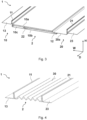
Fig. 3 is a perspective and cross-sectional view of a flashing member in an embodiment of the flashing member with two parts. -
Fig. 4 is a perspective and cross-sectional view of a flashing member in a further embodiment of the flashing member with a corrugated part. -
Fig. 5 is a perspective and cross-sectional view of a roof structure comprising a first roof window, a second roof window and a flashing member in an embodiment of the invention. -
Fig. 6 is an exploded perspective view of the flashing member in the embodiment ofFig. 3 . -
Fig. 7 is an end view of the flashing member ofFig. 6 in one engaged position. -
Fig. 8 is an end view of the flashing member ofFig. 6 in another engaged position. -
Fig. 9 is a perspective view of a roof structure with four roof penetrating structures, during a step of installation. -
Fig. 10 is a partial perspective views of the lower two roof penetrating roof structures ofFig. 9 , during a further step of installation. -
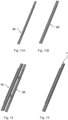
Figs. 11A and 11B are perspective views of a second part of a flashing member in alternative embodiments. -
Fig. 12 is a perspective views of a first part and a second part of a two-part flashing member during assembly. -
Fig. 13 is a perspective view of the two-part flashing member ofFig. 12 in an assembled condition. -
Fig. 14 is a perspective view of the roof structure ofFig. 9 during engagement of the two-part flashing member ofFig. 13 in an installation step. -
Figs. 15A and 15B are partial perspective views showing respective positions of the first part and the second part during adjustment of the mutual position in an installation step. -
Fig. 16 is a partial perspective view of the roof structure ofFig. 14 in a further installation step. -
Fig. 17 is a partial side sectional view showing the roof structure ofFig. 14 in a still further installation step. -
Figs. 18A and 18B are partial perspective views of a flashing member in yet further installation step. - In the following a detailed description of embodiments of the invention will be given with reference to the accompanying drawings. Starting out with
Fig. 1A an embodiment of a flashingmember 1 configured for covering a gap between a firstroof penetrating structure 100 and a secondroof penetrating structure 200 is shown. Theroof penetrating structures - The flashing
member 1 is situated above theroof penetrating structures roof penetrating structures member 1 comprises afirst engagement section 13 and asecond engagement section 23, both thefirst engagement section 13 and thesecond engagement section 23 are configured to be received in flashingreception grooves roof penetrating structures roof penetrating structures second engagement sections section 2. The connectingsection 2 defines a first plane P1 generally extending between anupper surface 2a and alower surface 2b of the connectingsection 2. - The flashing
member 1 is expandable in its width dimension. The connectingsection 2 is configured to be variable in its width and thereby cause the flashingmember 1 to be expandable. The width dimension may be understood as the dimension extending from left to right in theFigs. 1A - 1C and2A - 2C . - In the embodiment of
Figs. 1A to 1C , the connectingsection 2 comprises afirst part 10 and asecond part 20. Thefirst part 10 is formed such that it is slidably displaceable in relation to thesecond part 20. Thefirst part 10 therefore so to say receives thesecond part 20 as will be described in further detail in the following. - The
first part 10 and thesecond part 20 is in the embodiments shown each formed as a generally longitudinally extending profile element, having a length direction which in the installation situations to be described in the following is parallel to a slope direction D of the roof structure and extending into the plane of the drawing inFig. 1 . - As will be described in further detail below in connection with
Fig. 3 , theupper surface 2a of the connectingsection 2 is formed on a first leg portion of thefirst part 10 of the flashingmember 1 whereas thelower surface 2b is formed on a second leg portion of thefirst part 10, thereby delimiting a slit-shaped pocket in which thesecond part 20 is insertable by a leg portion and slidable so as to provide the adjustability of the flashingmember 1 aimed at. - Also shown in
Fig. 1A is a part of aroof structure 500 which may limit the depth of the flashingmember 1 in an installed state. - The first
roof penetrating structure 100 and the secondroof penetrating structure 200 may be roof windows, but other structures such as solar panels etc. are conceivable as well. - The flashing
member 1 further comprises afirst protrusion 11 and asecond protrusion 21. Thefirst protrusion 11 is situated between thefirst engagement portion 13 and the connectingsection 2. Thesecond protrusion 21 is situated between thesecond engagement portion 23 and the connectingsection 2. In the case that the gap of two adjacent roof penetrating structures is to be flashed, the flashingmember 1 is inserted in the gap between the firstroof penetrating structure 100 and the secondroof penetrating structure 200. - In
Fig. 1A , the flashingmember 1 is shown in an assembled, but not yet expanded position. This position may for instance correspond to a supply condition of the flashingmember 1. - The flashing
member 1 can be inserted from the top in the gap as its width is smaller than the width of the gap. The embodiment of a flashingmember 1 inserted in the gap can be seen inFig. 1B , in which the flashingmember 1 assumes an intermediate position, i.e. it is located within the gap between theroof penetrating structures flashing reception grooves - Once the flashing
member 1 has been inserted into the gap and is thus located in the appropriate height relative to theroof penetrating structures first protrusion 11 inserts thefirst engagement section 13 into the firstflashing reception groove 102. An oppositely directed force in direction F3 expands the connectingsection 2 in the width direction and inserts thesecond engagement section 23 into the secondflashing reception groove 202. The expandedflashing member 1, with the first andsecond engagement sections flashing reception grooves FIG 1C . The flashingmember 1 now assumes a position corresponding to a mounted condition of the flashingmember 1. - To prevent the first and the
second parts member 1, thefirst part 10 comprises afirst engagement portion 12, and thesecond part 20 comprises asecond engagement portion 22. Theseengagement portions member 1. For instance, thefirst part 10 and thesecond part 20 may be made of a sheet material substantially as shown inFigs. 1A - 1C . - The flashing
member 1 as a whole may be made from a sheet material that is formed by parallel folded portions, or bends. In particular the first andsecond protrusions second engagement portions member 1 could in principle be formed by extrusion, such as is indicated in the embodiment ofFigs. 1A - 1C . - In
Fig. 2A an alternative embodiment of the flashingmember 1 is shown, in which the connectingsection 2 comprises acorrugated part 30 that is configured to be stretched out to provide the variable width to the flashingmember 1. Thecorrugated part 30 may be formed such that it does not increase the depth of the flashingmember 1 substantially below the first and second engagement section. That means that almost all of thecorrugated part 30 may be located above the first andsecond engagement sections member 1 to flash a shallow gap, otherwise the corrugated part could collide with a roof structure. Thus, the flashingmember 1 may be said to have a non-protruding property. In a preferred embodiment, the flashingmember 1 may not protrude towards the roof in an installed state more than 30 mm. Thus, the flashing member can be used to flash the gap between roof penetrating structures that are installed low in relation to the roof and span over parts of theroof structure 500 that are high up in the roof structure, i.e. towards the exterior surface of the roof, for example a roof rafter, without having to modify such roof structures. The first plane may be defined as the plane incorporating all lower creases of thecorrugated section 30. - The first
flashing reception groove 102 of the firstroof penetrating structure 100 may as shown comprise first sealingprotrusions 101 configured to make sealing contact with thefirst engagement section 13. The same may apply mutatis mutandis to the secondflashing reception groove 202, which in the embodiment shown comprises second sealingprotrusions 201. - The
first protrusion 11 and thesecond protrusion 21 may be extending from the first plane by a distance of at least 15 mm. This may facilitate the use of the protrusions to push the engagement sections in or out of the flashing reception groove. The height of theprotrusions protrusion flashing reception groove protrusions - In the following, a method of installing a flashing
member 1 for covering the gap between a first roof penetrating structure and a second roof penetrating structure will be described in some detail. - The method will be described with particular reference to the embodiments described in the above and shown in
Figs. 1A - 1C and2A - 2C in connection with the firstroof penetrating structure 100 and the secondroof penetrating structure 200. - A first step comprises inserting the flashing
member 1 between the firstroof penetrating structure 100 and the secondroof penetrating structure 200. Arrow F1 indicates the movement of the flashing member that is necessary to place the flashingmember 1 in the gap. Thereafter, the flashingmember 1 can be expanded in the force directions indicated by F2, F3. For simplicity, the process is described for thefirst engagement section 13, but mutatis mutandis it applies to thesecond engagement section 23 as well. At first, theprotrusion 11 is moved towards the firstroof penetrating structure 100, and thefirst engagement section 13 is inserted in the firstflashing reception groove 102, where it is held by the sealingprotrusions 101. Thereafter, thesecond protrusion 21 is moved towards the direction of the secondroof penetrating structure 200 and thesecond engagement section 23 is inserted in the secondflashing reception groove 202, where thesecond engagement section 23 is held by thesecond sealing protrusions 201. This step also expands the flashingmember 1 and closes the gap that was between the first and secondroof penetrating structure - By the configuration of the flashing
member 1 according to the invention, it may further be possible to include a step of disengaging the flashingmember 1 from the first and secondroof penetrating structures first engagement section 13 out of the firstflashing reception groove 102 by applying a force onto thefirst protrusion 11. In case it is necessary to remove the flashing member from the gap when in an installed state, for example when a part of the roof underneath the flashing member needs to be accessed, this is a major advantage. To do that a spatula-like object may be wedged into a space between thefirst protrusion 11 and the firstroof penetrating structure 100. This allows the user to apply a force that is pulling the first engagement section out of the firstflashing reception groove 102. - In the following, two further embodiments will be described with reference to
Figs. 3 and 4 which show the flashingmember 1 in an inclined position indicating an exemplary position to be assumed by the flashingmember 1 in the mounted condition between two adjacent roof penetrating structures (not shown). Elements having the same or analogous function as in the above embodiments shown inFigs. 1 and2 are denoted by the same reference numerals throughout. Only differences to these embodiments will be described in detail. - In
Fig. 3 an embodiment of the flashingmember 1 is shown which corresponds to the embodiment ofFigs. 1A - 1C in that the flashingmember 1 is a two-part flashing member comprisingfirst part 10 andsecond part 20. Both the first andsecond parts first part 10 and thesecond part 20 as follows. - The
first part 10 comprises afirst leg portion 10a and asecond leg portion 10b forming apocket 10c between them. Thefirst leg portion 10a is formed by folding the material upon itself to form a double-walled structure. Thesecond leg portion 10b is located with a gap relative to the lower wall of thefirst leg portion 10a such that thepocket 10c formed is substantially slit-shaped. At the free end edge of thesecond leg portion 10b, thefirst engagement portion 12 is formed, here as a flange formed by being bent back by an angle of more than 90 degrees and less than 180 degrees relative to thesecond leg portion 10b. - The
second part 20 comprises aleg portion 20a insertable into thepocket 10c of thefirst part 10 to form a telescopic joint. The free end of theleg portion 20a comprises thesecond engagement portion 22, here formed as a flange formed by being bent back by an angle of more than 90 degrees and less than 180 degrees relative to theleg portion 20a. - Also indicated in
Fig. 3 are general directions: Slope direction D, width direction W and height direction H. - It is noted that for the
second engagement section 23 to coincide with the plane of thefirst engagement section 13, the bend that is connecting thesecond engagement section 23 with thesecond protrusion 21 has a different height from the bend connecting thesecond protrusion 21 with theleg portion 20a. This compensates for the fact that thesecond part 20 is partly located below thefirst part 10, partly above, thus allowing the insertion of theleg portion 20a of thesecond part 20 into the slit-shapedpocket 10c formed in thefirst part 10 in the width direction W. Thus, in a configuration in which theroof penetrating structures engagement sections protrusions roof penetrating structures - In
Fig. 4 an embodiment of a flashingmember 1 is shown that has acorrugated part 30, and that corrugated part inFig. 4 is located at the same height or above theengagement sections roof penetrating structures - Turning now to
Fig. 5 , the flashingmember 1 of the embodiment ofFig. 3 is shown in its mounted condition between two adjacent roof penetrating structures in the form ofroof windows - The configuration of such roof windows is described in more detail in Applicant's published international application
WO 2023/186250 A1 , including an interface unit which forms the point of interaction with a flashing assembly of a single, isolated roof window. - As shown in
Fig. 5 , thefirst engagement portion 13 of thefirst part 10 of the flashingmember 1 is inserted into the firstflashing reception groove 102 of an interface unit of the left-hand roof window 100 and thesecond engagement portion 23 of thesecond part 20 is inserted into the secondflashing reception groove 202 of an interface unit of the right-hand roof window 200. Thefirst protrusion 11 has been pushed into engagement with the interface unit of the left-hand roof window 100 and correspondingly thesecond protrusion 21 into engagement with the interface unit of the right-hand roof window 200 such that watertightness is ensured, just as therespective protrusions flashing reception grooves - The interaction between the
first part 10 and thesecond part 20 of the two-part flashing member 1 of the embodiment ofFig. 3 is shown in more detail with particular reference toFigs. 6 to 8 :
During assembly of the flashingmember 1, thesecond part 20 is introduced by itsleg portion 20a including thesecond engagement portion 22 into thepocket 10c formed between thefirst leg portion 10a and thesecond leg portion 10b of thefirst part 10. At the point of passage of thesecond engagement portion 22 over thefirst engagement portion 12, one or both of the first andsecond parts - Once brought into engagement, the mutual position between the first and
second parts - In the position shown in
Fig. 7 , a maximum measure Dmax of the distance between the first andsecond protrusions first engagement portion 12 is in engagement with thesecond engagement portion 22, thus preventing the first andsecond parts - In the position shown in
Fig. 8 , a minimum measure Dmin is indicated. In this position, theleg portion 20a of thesecond part 20 has been inserted into thepocket 10c to its full extent. - Turning now to
Figs. 9 to 18B , further aspects of the invention will be described in some detail with reference to a roof structure comprising fourroof penetrating structures - The two lowermost
roof penetrating structures bottom flashing member - Further components of the flashing assembly comprise a set of parts to form a two-
part flashing member 1 of the type described with reference toFigs 1-8 . Depending on the spacing between pairs of neighbouringroof penetrating structures second parts 20 and 20' is selected as indicated inFigs. 11A and 11B . - A
first part 10 is provided, shown inFig. 12 . Thefirst part 10 is formed with a first leg portion and a second leg portion forming a pocket between them (not indicated in detail) substantially as shown inFigs. 7 and 8 . Furthermore, thefirst part 10 comprises a first protrusion 11 (cf.Fig. 17 ). - It is noted that in contrast to the embodiments of the parts of the flashing member of the embodiments shown in
Figs. 1 to 8 , the first andsecond parts Figs. 11A to 18B do not comprise respective flat engagement sections in parallel with the first plane P. However, the principles presently described are universally applicable to flashing members with and without such flat engagement sections. - In order to improve the installation conditions even further, the flashing assembly is provided with holding means. The holding means may be temporary to provide a provisional hold in an installation step, or form part of the permanent structure securing the flashing assembly to the roof penetrating structure(s) or the roof structure.
- The holding means ensure that flashing members to be positioned between neighbouring roof penetrating structures with the length direction of the flashing member in parallel with the slope direction.
- The holding means may be positive or non-positive.
- The term "positive engagement" (German: formschlüssig) is to be interpreted as encompassing mechanical coupling of two otherwise separate components such that the design and geometry of the components prevent the coupling from being released unintentionally by forces to which the components are subjected during use, including in particular such mechanical couplings in which mutually complementary shapes of the respective components fit together in the engaged position, and in which intentional movement of at least one of the components out of the engaged position is required, typically involving at least partial movement of part(s) of one or both components in a direction at an angle to the intended movement. In other words, the term positive engagement is to be understood as any form of form-locking coupling in which the shapes or geometrical forms of two components interlock with each other in such a way that they create an engagement preventing disengagement until intentional release is carried out by an active or conscious action by a user.
- As opposed hereto, "non-positive engagement" (German: kraftschlüssig) involves such engagement which only requires a force in the direction of intended movement to obtain release. A non-exhaustive list of examples of non-positive engagement means include frictional connections, magnetic connections, "soft" snap connections, etc. in which the engagement between the components is enabled by means of forces mainly in the tangential direction rather than the normal direction.
- The holding means may be placed on any flashing member of the flashing assembly.
- The holding means may comprise a substantially planar lug extending in a plane substantially parallel to any plane spanned by portions of a flashing member. The planar lug may be formed to extend in the plane spanned by the height direction H and slope direction D of a flashing member.
- Such planar lug or lugs may be formed to protrude from the flashing member.
- The shape of each planar lug may be chosen arbitrarily to conform to manufacturing, transportation, or installation requirements.
- Each planar lug may be foldable about a folding line substantially parallel to the height direction H or slope direction D.
- In the embodiment shown in more detail in
Figs. 16 and 17 , a substantiallyplanar lug 14 is formed on thebottom flashing member 144 of the firstroof penetrating structure 100. - The
planar lug 14 here has a trapezoidal shape and protrudes from a perpendicular flange of thebottom flashing member 144 to extend in the plane spanned by the height direction H and the slope direction D. - The
planar lug 14 is configured to be foldable about a folding line substantially parallel to the slope direction D to abut thefirst protrusion 11 of thefirst part 10 of the flashingmember 1 in a mounted condition of the flashing assembly. - Thus, in the mounted condition the
trapezoidal lug 14 assumes a folded-back position substantially in parallel with its original plane and acts as a force-locking engagement means in hindering the flashingmember 1 from sliding along the sloping roof by frictional forces. - The engagement may be reinforced by clamping the
trapezoidal lug 14 manually, possibly by means of a suitable tool. - In the embodiment shown in more detail in
Figs. 18A and 18B , a substantiallyplanar lug 15 is formed on thefirst protrusion 11 of thefirst part 10 of the flashingmember 1. - The
planar lug 15 has a rectangular shape and protrudes from thefirst protrusion 11 to extend in the planned spanned by the height direction H and the slope direction D. - The
planar lug 15 is configured to be foldable about a folding line substantially parallel to the height direction H to a position at right angles with its original plane to be brought into abutment with a portion of the firstroof penetrating structure 100, typically at a corner of the stationary frame of a roof window, or at a portion of any insulation frame mounted to the frame. In this way, therectangular lug 15 provides a form-locking engagement with the firstroof penetrating structure 100, thus improving the retention of the flashingmember 1 even further. -
- 1
- flashing member
- 2
- connecting section
- 2a upper surface
- 2b lower surface
- 10
- first part
- 10a first leg portion
- 10b second leg portion
- 10c pocket
- 11
- first protrusion
- 12
- first engagement portion
- 13
- first engagement section
- 14
- trapezoid lug
- 15
- rectangular lug
- 20
- second part
20a leg portion - 20'
- second part (alternative embodiment)
- 21
- second protrusion
- 22
- second engagement portion
- 23
- second engagement section
- 30
- corrugated part
- 100
- first roof penetrating structure
- 101
- first sealing protrusions
- 102
- first flashing reception groove
- 144
- bottom flashing member
- 200
- second roof penetrating structure
- 201
- second sealing protrusions
- 202
- second flashing reception groove
- 244
- bottom flashing member
- 300
- third roof penetrating structure
- 400
- fourth roof penetrating structure
- 500
- roof structure
- F1
- direction indicator
- F2
- direction indicator
- F3
- direction indicator
- P1
- first plane
- D
- slope direction
- W
- width direction
- H
- height direction
- Dmax
- maximum measure
- Dmin
- minimum measure
Claims (15)
- A flashing member (1) for covering a gap between a first roof penetrating structure (100) and a second roof penetrating structure (200), the flashing member (1) comprising a first engagement section (13) configured for engagement with the first roof penetrating structure (100), a second engagement section (23) configured for engagement with the second roof penetrating structure (200), and a connecting section (2) extending between the first engagement section (13) and the second engagement section (23), the connecting section (2) defining a first plane (P1), characterised in that
the width of the connecting section (2) is variable, that the flashing member (1) further comprises a first protrusion (11) and a second protrusion (21) both projecting away from the first plane (P1), and that the first engagement section (13) and the second engagement section (23) are substantially flat and extending in parallel to the first plane. - A flashing member (1) according to claim 1, wherein the first and second engagement sections (13, 23) substantially coincide with the first plane (P1).
- A flashing member according to claim 1 or 2, wherein the first protrusion (11) and the second protrusion (21) are projecting perpendicularly away from the first plane (P1).
- A flashing member according to any one of the preceding claims, wherein the connecting section (2) comprises a first part (10) and a second part (20), and wherein the first part (10) is slidably displaceable in relation to the second part (20) along the first plane (P1).
- A flashing member according to claim 4, wherein the first part (10) comprises a first engagement portion (12), and the second part (20) comprises a second engagement portion (22), and wherein the first engagement portion (12) and the second engagement portion (22) are configured to engage each other to prevent the first part (10) and the second part (20) from coming apart.
- A flashing member according to any one of claims 4 or 5, wherein the first part (10) comprises a first leg portion (10a) and a second leg portion (10b) forming a pocket (10c) between them, and wherein the second part (20) comprises a leg portion (20a) insertable into said pocket (10c) to form a telescopic joint.
- A flashing member according to any one of claims 1 to 5, wherein the connecting section (2) comprises a corrugated part (30).
- A flashing member (1) according to any one of the preceding claims, wherein the first protrusion (11) protrudes from the connecting section (2) by at least 15 mm, and the second protrusion (21) protrudes from the connecting section (2) by at least 15 mm.
- A flashing member (1) according to any one of the preceding claims, wherein a flashing reception groove (102) of the first roof penetrating structure (100) comprises first sealing protrusions (101) configured to make sealing contact with the first engagement section (13).
- A roof structure comprising a first roof window, a second roof window and a flashing member (1) according to any one of the preceding claims, wherein the flashing member (1) is installed between the first roof window and the second roof window, said first roof window constituting the first roof penetrating structure (100) and said second roof window constituting the second roof penetrating structure (200).
- A method of adapting a flashing member (1) configured for covering a gap between a first roof penetrating structure (100) and a second roof penetrating structure (200), said flashing member (1) comprising a first engagement section (13) configured for engagement with the first roof penetrating structure (100) and a second engagement section configured for engagement with the second roof penetrating structure (200), said flashing member being placed between the first roof penetrating structure and the second roof penetrating structure, with a connecting section (2) extending between the first engagement section (13) and the second engagement section (23), the connecting section (2) defining a first plane (P1), characterised in that said method comprises changing the width of the connecting section in a width direction by applying a force onto a first protrusion (11) in a first force direction (F2), and applying a force onto a second protrusion (21) in a second force direction (F3), said first protrusion (11) and said second protrusion (21) both projecting away from the first plane (P1), and said second force direction being opposite to the first force direction.
- A method according to claim 11, where the first force direction is towards the first roof penetrating structure (100) and the second force direction is towards the second roof penetrating structure (200), so that the first engagement section (13) engages with the first roof penetrating structure and the second engagement section engages with the second roof penetrating structure.
- A method according to claim 11, comprising the further step of disengaging the flashing member (1) from the roof penetrating structures (100, 200) where the first force direction is towards the second roof penetrating structure (100) and the second force direction is towards the first roof penetrating structure (200), so that the first engagement section (13) disengages from the first roof penetrating structure and the second engagement section disengages from the second roof penetrating structure.
- A method according to 12, where the first engagement section (13) is inserted into a first flashing reception groove (102) and where the second engagement section (23) is inserted into a second flashing reception groove (202).
- A method according to 13, where the first engagement section (13) is pulled out of a first flashing reception groove (102) and where the second engagement section (23) is pulled out of a second flashing reception groove (202).
Priority Applications (3)
| Application Number | Priority Date | Filing Date | Title |
|---|---|---|---|
| CN202423030164.7U CN223634218U (en) | 2023-12-11 | 2024-12-09 | Waterproof components |
| US18/974,000 US20250188745A1 (en) | 2023-12-11 | 2024-12-09 | Flashing member, roof structure and method of adapting a flashing member for covering a gap |
| EP25207005.7A EP4722465A2 (en) | 2024-10-04 | 2025-10-06 | A kit of covering members, a method of manufacturing a kit of covering members, and use of the kit of covering members |
Applications Claiming Priority (1)
| Application Number | Priority Date | Filing Date | Title |
|---|---|---|---|
| DKPA202370608 | 2023-12-11 |
Publications (2)
| Publication Number | Publication Date |
|---|---|
| EP4571008A1 true EP4571008A1 (en) | 2025-06-18 |
| EP4571008B1 EP4571008B1 (en) | 2026-05-20 |
Family
ID=93013919
Family Applications (1)
| Application Number | Title | Priority Date | Filing Date |
|---|---|---|---|
| EP24204762.9A Active EP4571008B1 (en) | 2023-12-11 | 2024-10-04 | METHOD FOR ADJUSTING A COVER ELEMENT TO COVER A GAP BETWEEN ROOF STRUCTURES |
Country Status (3)
| Country | Link |
|---|---|
| US (1) | US20250188745A1 (en) |
| EP (1) | EP4571008B1 (en) |
| CN (1) | CN223634218U (en) |
Families Citing this family (1)
| Publication number | Priority date | Publication date | Assignee | Title |
|---|---|---|---|---|
| DK182324B1 (en) * | 2024-10-04 | 2026-04-17 | Vkr Holding As | A flashing assembly for use between two roof windows mounted in an inclined roof structure, a group of roof windows mounted with such a flashing assembly, and a method for mounting a flashing assembly between two roof windows |
Citations (5)
| Publication number | Priority date | Publication date | Assignee | Title |
|---|---|---|---|---|
| DK154099B (en) | 1982-02-26 | 1988-10-10 | Rasmussen Holding As V Kann | COMBINATION COVER FRAME FOR ROOF WINDOWS TO BE BUILT IN SIDE OF THE HIND |
| WO2003074812A1 (en) * | 2002-03-07 | 2003-09-12 | Vkr Holding A/S | Sheet flashing member and flashing kit comprising such sheet flashing members |
| ES1070303U (en) * | 2008-04-10 | 2009-07-20 | Reinhard Eder, Blechbaugesellschaft M.B.H. | ASSEMBLY KIT FOR THE INSTALLATION AND / OR CONSTRUCTION OF ROOFING STRUCTURES. |
| EP1521888B1 (en) * | 2002-07-17 | 2010-11-24 | VKR Holding A/S | Sheet flashing member and a flashing kit |
| WO2023186250A1 (en) | 2022-03-31 | 2023-10-05 | Vkr Holding A/S | A roof window, a kit with a covering assembly, and a method for mounting a roof window |
-
2024
- 2024-10-04 EP EP24204762.9A patent/EP4571008B1/en active Active
- 2024-12-09 CN CN202423030164.7U patent/CN223634218U/en active Active
- 2024-12-09 US US18/974,000 patent/US20250188745A1/en active Pending
Patent Citations (5)
| Publication number | Priority date | Publication date | Assignee | Title |
|---|---|---|---|---|
| DK154099B (en) | 1982-02-26 | 1988-10-10 | Rasmussen Holding As V Kann | COMBINATION COVER FRAME FOR ROOF WINDOWS TO BE BUILT IN SIDE OF THE HIND |
| WO2003074812A1 (en) * | 2002-03-07 | 2003-09-12 | Vkr Holding A/S | Sheet flashing member and flashing kit comprising such sheet flashing members |
| EP1521888B1 (en) * | 2002-07-17 | 2010-11-24 | VKR Holding A/S | Sheet flashing member and a flashing kit |
| ES1070303U (en) * | 2008-04-10 | 2009-07-20 | Reinhard Eder, Blechbaugesellschaft M.B.H. | ASSEMBLY KIT FOR THE INSTALLATION AND / OR CONSTRUCTION OF ROOFING STRUCTURES. |
| WO2023186250A1 (en) | 2022-03-31 | 2023-10-05 | Vkr Holding A/S | A roof window, a kit with a covering assembly, and a method for mounting a roof window |
Also Published As
| Publication number | Publication date |
|---|---|
| EP4571008B1 (en) | 2026-05-20 |
| US20250188745A1 (en) | 2025-06-12 |
| CN223634218U (en) | 2025-12-05 |
Similar Documents
| Publication | Publication Date | Title |
|---|---|---|
| KR101355881B1 (en) | Fixing structure of solar battery module, frame for the solar battery module, and fixing member | |
| EP3704791B1 (en) | Solar panel mount with compression spacer systems and methods | |
| US20250188745A1 (en) | Flashing member, roof structure and method of adapting a flashing member for covering a gap | |
| US20240337108A1 (en) | Flashing assembly for use between two roof windows mounted in an inclined roof structure, a group of roof windows mounted using such a flashing assembly, and a method for mounting a flashing assembly between two roof windows | |
| US5038543A (en) | Standing seam roof assembly | |
| EP2192248B1 (en) | Roof component flashing, a flashing system and a method of flashing | |
| US20240328162A1 (en) | Flashing assembly comprising a top flashing arrangement, a roof element system comprising such a flashing assembly, and a method of manufacturing a flashing assembly | |
| HU215339B (en) | Flashing arrangement for mounting of a roof element, in particular a roof window in a roof | |
| KR101554425B1 (en) | External panel fastening structure and method of the same | |
| AU2015208670B9 (en) | Construction of a building structure with a weatherproof join | |
| EP3243976B1 (en) | Panel splice connector for linear ceiling panels | |
| CN100439629C (en) | Flashing device and method for mounting a roof penetrating structure by means of a flashing device | |
| EP4571010A1 (en) | A cover assembly and a method for interconnecting cover members | |
| EP4538476A1 (en) | Top covering member, a weather-proofing system for a roof penetrating structure, and a sloping roof penetrating window | |
| KR101392237B1 (en) | Boltless exterior board structure of flashing-caped type | |
| JP2966345B2 (en) | Lining exterior structure and construction method | |
| CN216893176U (en) | Gable waterproof construction | |
| EP4700200A1 (en) | Engagement element for any window installation to the universal thermoprofile and method of its usage | |
| KR101739116B1 (en) | The connecter of prefabicated panel for buliding roof and exterior wall | |
| GB2191529A (en) | Window frame | |
| EP4442925A1 (en) | A flashing assembly comprising a top flashing arrangement, a roof element system comprising such a flashing assembly, and a method of manufacturing a flashing assembly | |
| JP4313737B2 (en) | Exterior wall material mounting structure and exterior wall material mounting method | |
| WO2023186247A1 (en) | A roof window and a method for mounting a roof window | |
| EP1312723B1 (en) | Junction device for connecting two coplanar panels | |
| EP4599136A1 (en) | A method for mounting a roof window, a kit comprising a roof window and at least two flashing members, a flashing member, a roof window, and a roof structure with a roof window mounted therein |
Legal Events
| Date | Code | Title | Description |
|---|---|---|---|
| PUAI | Public reference made under article 153(3) epc to a published international application that has entered the european phase |
Free format text: ORIGINAL CODE: 0009012 |
|
| STAA | Information on the status of an ep patent application or granted ep patent |
Free format text: STATUS: THE APPLICATION HAS BEEN PUBLISHED |
|
| AK | Designated contracting states |
Kind code of ref document: A1 Designated state(s): AL AT BE BG CH CY CZ DE DK EE ES FI FR GB GR HR HU IE IS IT LI LT LU LV MC ME MK MT NL NO PL PT RO RS SE SI SK SM TR |
|
| STAA | Information on the status of an ep patent application or granted ep patent |
Free format text: STATUS: REQUEST FOR EXAMINATION WAS MADE |
|
| GRAP | Despatch of communication of intention to grant a patent |
Free format text: ORIGINAL CODE: EPIDOSNIGR1 |
|
| STAA | Information on the status of an ep patent application or granted ep patent |
Free format text: STATUS: GRANT OF PATENT IS INTENDED |
|
| 17P | Request for examination filed |
Effective date: 20251208 |
|
| RIC1 | Information provided on ipc code assigned before grant |
Ipc: E04D 13/03 20060101AFI20251211BHEP Ipc: E04D 13/147 20060101ALI20251211BHEP |
|
| INTG | Intention to grant announced |
Effective date: 20260113 |
|
| GRAS | Grant fee paid |
Free format text: ORIGINAL CODE: EPIDOSNIGR3 |
|
| GRAA | (expected) grant |
Free format text: ORIGINAL CODE: 0009210 |
|
| STAA | Information on the status of an ep patent application or granted ep patent |
Free format text: STATUS: THE PATENT HAS BEEN GRANTED |