EP4570999A1 - Adjustable structure of a foot sensor sensing distance - Google Patents
Adjustable structure of a foot sensor sensing distance Download PDFInfo
- Publication number
- EP4570999A1 EP4570999A1 EP24157880.6A EP24157880A EP4570999A1 EP 4570999 A1 EP4570999 A1 EP 4570999A1 EP 24157880 A EP24157880 A EP 24157880A EP 4570999 A1 EP4570999 A1 EP 4570999A1
- Authority
- EP
- European Patent Office
- Prior art keywords
- snap
- cylinder portion
- adapter sleeve
- adjustable structure
- structure according
- Prior art date
- Legal status (The legal status is an assumption and is not a legal conclusion. Google has not performed a legal analysis and makes no representation as to the accuracy of the status listed.)
- Granted
Links
Images




Classifications
-
- E—FIXED CONSTRUCTIONS
- E03—WATER SUPPLY; SEWERAGE
- E03D—WATER-CLOSETS OR URINALS WITH FLUSHING DEVICES; FLUSHING VALVES THEREFOR
- E03D5/00—Special constructions of flushing devices, e.g. closed flushing system
- E03D5/10—Special constructions of flushing devices, e.g. closed flushing system operated electrically, e.g. by a photo-cell; also combined with devices for opening or closing shutters in the bowl outlet and/or with devices for raising/or lowering seat and cover and/or for swiveling the bowl
- E03D5/105—Special constructions of flushing devices, e.g. closed flushing system operated electrically, e.g. by a photo-cell; also combined with devices for opening or closing shutters in the bowl outlet and/or with devices for raising/or lowering seat and cover and/or for swiveling the bowl touchless, e.g. using sensors
-
- G—PHYSICS
- G01—MEASURING; TESTING
- G01S—RADIO DIRECTION-FINDING; RADIO NAVIGATION; DETERMINING DISTANCE OR VELOCITY BY USE OF RADIO WAVES; LOCATING OR PRESENCE-DETECTING BY USE OF THE REFLECTION OR RERADIATION OF RADIO WAVES; ANALOGOUS ARRANGEMENTS USING OTHER WAVES
- G01S17/00—Systems using the reflection or reradiation of electromagnetic waves other than radio waves, e.g. lidar systems
- G01S17/02—Systems using the reflection of electromagnetic waves other than radio waves
- G01S17/04—Systems determining the presence of a target
-
- G—PHYSICS
- G01—MEASURING; TESTING
- G01S—RADIO DIRECTION-FINDING; RADIO NAVIGATION; DETERMINING DISTANCE OR VELOCITY BY USE OF RADIO WAVES; LOCATING OR PRESENCE-DETECTING BY USE OF THE REFLECTION OR RERADIATION OF RADIO WAVES; ANALOGOUS ARRANGEMENTS USING OTHER WAVES
- G01S7/00—Details of systems according to groups G01S13/00, G01S15/00, G01S17/00
- G01S7/48—Details of systems according to groups G01S13/00, G01S15/00, G01S17/00 of systems according to group G01S17/00
- G01S7/481—Constructional features, e.g. arrangements of optical elements
- G01S7/4811—Constructional features, e.g. arrangements of optical elements common to transmitter and receiver
- G01S7/4813—Housing arrangements
-
- E—FIXED CONSTRUCTIONS
- E03—WATER SUPPLY; SEWERAGE
- E03D—WATER-CLOSETS OR URINALS WITH FLUSHING DEVICES; FLUSHING VALVES THEREFOR
- E03D11/00—Other component parts of water-closets, e.g. noise-reducing means in the flushing system, flushing pipes mounted in the bowl, seals for the bowl outlet, devices preventing overflow of the bowl contents; devices forming a water seal in the bowl after flushing, devices eliminating obstructions in the bowl outlet or preventing backflow of water and excrements from the waterpipe
- E03D11/13—Parts or details of bowls; Special adaptations of pipe joints or couplings for use with bowls, e.g. provisions in bowl construction preventing backflow of waste-water from the bowl in the flushing pipe or cistern, provisions for a secondary flushing, for noise-reducing
Definitions
- the invention relates to a sensor fitting, in particular to a position adjustable mounting structure of a sensor.
- a foot detection sensor can be disposed on a sanitary ware, such as a toilet or a urinal, for detecting downwardly whether a human foot is standing in the vicinity, so as to activate a corresponding intelligent accessory of the toilet or the urinal, such as opening the toilet cover and starting the heating device.
- a sanitary ware such as a toilet or a urinal
- the structure of the foot sensor is relatively fixed, as is its downward detectable range.
- a too high finished floor level at the user's site can lead to a low mounting position of the foot sensor, which results for example in the emission of a detection signal directly onto the finished floor level.
- a foot laser sensor in this state would receive a direct reflection from the finished floor level, causing the actuator to be triggered continuously and not be able to accurately sense the presence or absence of a foot.
- a too low finish floor level at the user's site can lead to a high mounting position of the foot sensor, which results in the emitted laser being too far away from the finish floor level and the laser blind area being too large.
- the actuator cannot be triggered when the user triggers the function with the foot.
- the invention aims at providing an improved adjustable mounting structure for a foot sensor.
- the present application provides an adjustable mounting structure for a foot detection sensor along claim 1.
- the adapter sleeve is made of a rigid material, such as a metal, a ceramic or a polymeric material.
- the outer edge of the panel is provided with positioning pieces for adapting to the mounting hole of the sanitary ware.
- the foot sensor When in use, the foot sensor can be fixed in the adapter sleeve, the foot sensor with the adapter sleeve extending into the desired position in the cylinder portion of the mounting frame. Then the snap ring can be sleeved over the cylinder portion to drive the claws on the cylinder portion to shift inward from the first position to the second position. Then, the snap ring can be rotated to shift the claws to the third position, thus firmly gripping the cylinder portion and the adapter sleeve. When subsequent adjustments are required, the reverse operation can be performed.
- Beneficial effects of the invention include: the height of the foot sensor in the mounting hole of the sanitary ware can be adjusted up and down according to the user's actual finished floor level, so as to adjust the distance between the foot sensor and the finished floor; the at least two fixing segments of the snap ring can make the mounting fast and firm.
- an embodiment of the present application provides an adjustable mounting structure of a foot sensor, comprising a mounting frame 100, a snap ring 200 and an adapter sleeve 300; wherein the mounting frame 100 has a cylinder portion 120 matched with the adapter sleeve 300, and a wall 121 of the cylinder portion 120 is provided with four radially inwardly deflectable claws 122, and the claws 122 are configured to be in a first position P1 when not deflected.
- the adapter sleeve 300 at least partially extends into the cylinder portion 120, and the sensing distance of the sensor 400 connected to the adapter sleeve is adjusted by the position of the adapter sleeve extending into the cylinder portion 120.
- the number of claws 122 can be more or less as long as radial deflection can be achieved to clamp the adapter sleeve 300.
- the number of claws can be one, two, three, four, five or six.
- the adapter sleeve 300 is substantially cylindrical in shape and is sleeved around the body of the sensor 400, and the rod of the sensor 400 is exposed from the adapter sleeve 300.
- the adapter sleeve 300 includes a plurality of circumferential grooves 311 disposed in the axial direction, such as the illustrated circumferential grooves 311a, 311b, 311c and 311d. These circumferential grooves 311 engage the claws 122 on the cylinder portion 120 of the mounting frame 100, so that the adapter sleeve 300 is engaged with the mounting frame 100.
- the snap ring 200 is fitted on the outer side of the cylinder portion 120, and the adapter sleeve 300 is engaged with the mounting frame 100 by deflecting the claws 122 radially inward.
- the snap ring 200 may have four first snap-in portions 210a and 210b (only two first snap-in portions are shown in FIG. 9 ) and four second snap-in portions 220a, 220b, 220c and 220d corresponding to the number of claws, and one first snap-in portion and one second snap-in portion are disposed adjacent to each other.
- the claw 122 deflects inward to the second position P2 along the radial direction R, and continues to deflect inward to the third position P3 when the claw is engaged with the second snap-in portion 220a.
- the claw 122a at the second position P2 at least partially enters one of the circumferential grooves 311 of the adapter sleeve 300, thereby limiting the axial L movement of the cylinder portion 120 and the adapter sleeve 300.
- the claw 122a closely cooperates with the circumferential groove 311 of the adapter sleeve 300, thereby further limiting the circumferential P movement of the cylinder portion 120 and the adapter sleeve 300.
- the cylinder portion 120 can be made of an elastic material, such as polyethylene and polyurethane and other synthetic material.
- the claws 122 are connected to the wall 121 at one end and are cantilevered at the cylinder portion 120.
- the first snap-in portion 210a is a groove provided on the inner surface of the snap ring, and as shown in FIG. 9 , the groove is provided on the body of the snap ring, the depth of which is formed to enable the claw to shift to the second position P2.
- the second snap-in portion 220a is an arc surface disposed on the inner surface of the snap ring, and the radius of curvature of the arc surface is smaller than that of the circle with the inner surface of the snap ring, so that the arc surface can drive the claws to continue to move radially inward to the third position P3.
- a limiting abutment stop 230 is disposed on one side of the groove that matches first with the claws to prevent the claws from detaching from the groove due to axial movement.
- first snap-in portion and the second snap-in portion can be consecutively disposed on the inner surface of the snap ring, or disposed at intervals, that is, with gaps there between.
- a pair of protrusions 123 which can be wedge-shaped or otherwise shaped protrusions, is also disposed on the outer surface of the wall 121 of the cylinder portion 120 at the position corresponding to the claws, and the protrusions cooperate with the outer edge 240 of the snap ring to limit the axial movement of the snap ring.
- the adapter sleeve 300 may be made of a rigid material, such as a metal, a ceramic or a polymer material, or may be made of a flexible material, such as silica gel, rubber or other synthetic material.
- the mounting frame can also be used as a mounting hole cover plate of the sanitary ware.
- the mounting frame 100 may include a panel 110 extending radially outward from the wall 121 of the cylinder portion 120, and there may be an opening 1121 at the position of the panel 110 corresponding to the cylinder portion 120, and the opening may be provided with a cover plate made of light-transmitting material, thereby allowing the sensor to project detection light, such as laser or infrared light, and receive reflection.
- the outer edge 112 of the panel 110 can be provided with a positioning piece 113 for fitting, such as clamping, inside the mounting hole of a sanitary ware.
- the working principle of the adjusting structure is as follows: when in use, the foot sensor 400 is fixed in the adapter sleeve 300, the foot sensor with the adapter sleeve 300 is extended into a desired position in the cylinder portion 120 of the mounting frame 100, and then the snap ring 200 is sleeved over the cylinder portion 120, so that the first snap-in portion engages the claw 122 and drives the claws 122 to shift inward from the first position P1 to the second position P2. Then, the snap ring 200 is rotated, so that the second snap-in portion continues to drive the claws 122 to shift to the third position P3, thereby firmly clamping the cylinder portion 120 and the adapter sleeve 300 in place. When subsequent adjustments are required, the reverse operation can be performed to release the snap ring and make the adjustment.
- Sensors suitable for the structure of the present application are, for example, laser sensors or infrared sensors.
Landscapes
- Engineering & Computer Science (AREA)
- Physics & Mathematics (AREA)
- Remote Sensing (AREA)
- Computer Networks & Wireless Communication (AREA)
- General Physics & Mathematics (AREA)
- Radar, Positioning & Navigation (AREA)
- Electromagnetism (AREA)
- Aviation & Aerospace Engineering (AREA)
- Health & Medical Sciences (AREA)
- Life Sciences & Earth Sciences (AREA)
- Hydrology & Water Resources (AREA)
- Public Health (AREA)
- Water Supply & Treatment (AREA)
- Geophysics And Detection Of Objects (AREA)
- Snaps, Bayonet Connections, Set Pins, And Snap Rings (AREA)
Abstract
Description
- The invention relates to a sensor fitting, in particular to a position adjustable mounting structure of a sensor.
- Conventionally, a foot detection sensor can be disposed on a sanitary ware, such as a toilet or a urinal, for detecting downwardly whether a human foot is standing in the vicinity, so as to activate a corresponding intelligent accessory of the toilet or the urinal, such as opening the toilet cover and starting the heating device. However, the structure of the foot sensor is relatively fixed, as is its downward detectable range. Thus, a too high finished floor level at the user's site can lead to a low mounting position of the foot sensor, which results for example in the emission of a detection signal directly onto the finished floor level. For example, a foot laser sensor in this state would receive a direct reflection from the finished floor level, causing the actuator to be triggered continuously and not be able to accurately sense the presence or absence of a foot. Likewise, a too low finish floor level at the user's site can lead to a high mounting position of the foot sensor, which results in the emitted laser being too far away from the finish floor level and the laser blind area being too large. As a result, the actuator cannot be triggered when the user triggers the function with the foot.
- It is necessary to adjust the position of the foot sensor on the toilet to cope with different finish floor levels. However, currently available foot sensors are disposed directly in the void of the sanitary ware without any adjustment structure.
- The invention aims at providing an improved adjustable mounting structure for a foot sensor. To solve this problem, the present application provides an adjustable mounting structure for a foot detection sensor along claim 1.
- Preferred embodiments are defined in the dependent claims.
- In some embodiments, the adapter sleeve is made of a rigid material, such as a metal, a ceramic or a polymeric material.
- In some embodiments, the outer edge of the panel is provided with positioning pieces for adapting to the mounting hole of the sanitary ware.
- When in use, the foot sensor can be fixed in the adapter sleeve, the foot sensor with the adapter sleeve extending into the desired position in the cylinder portion of the mounting frame. Then the snap ring can be sleeved over the cylinder portion to drive the claws on the cylinder portion to shift inward from the first position to the second position. Then, the snap ring can be rotated to shift the claws to the third position, thus firmly gripping the cylinder portion and the adapter sleeve. When subsequent adjustments are required, the reverse operation can be performed.
- Beneficial effects of the invention include: the height of the foot sensor in the mounting hole of the sanitary ware can be adjusted up and down according to the user's actual finished floor level, so as to adjust the distance between the foot sensor and the finished floor; the at least two fixing segments of the snap ring can make the mounting fast and firm.
- Other objects, features, and advantages of the invention will become apparent from the following detailed description of the preferred but non-limiting embodiment. The description is made with reference to the accompanying drawings, in which:
- FIG. 1
- shows a schematic diagram of an adjustable mounting structure of a foot sensor according to the present application;
- FIG. 2
- shows a three-dimensional schematic diagram of a mounting frame of the adjustable mounting structure according to the present application;
- FIG. 3
- shows a bottom view schematic diagram of the mounting frame of the adjustable mounting structure according to the present application;
- FIG. 4
- shows a side view schematic diagram of a first viewing angle of the mounting frame of the adjustable mounting structure according to the present application;
- FIG. 5
- shows side view schematic diagram of a second viewing angle of the mounting frame of the adjustable mounting structure according to the present application;
- FIG. 6
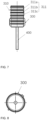
- shows a three-dimensional schematic diagram of an adapter sleeve combined with a sensor in the adjustable mounting structure according to the present application;
- FIG. 7
- shows a side view schematic diagram of the adapter sleeve combined with the sensor in the adjustable mounting structure according to the present application;
- FIG. 8
- shows a bottom view schematic diagram of the adapter sleeve combined with the sensor in the adjustable mounting structure according to the present application;
- FIG. 9
- shows a three-dimensional schematic diagram of a snap ring of the adjustable mounting structure according to the present application;
- FIG. 10
- shows a bottom view schematic diagram of the snap ring of the adjustable mounting structure according to the present application;
- FIG. 11
- shows a side view schematic diagram of the snap ring of the adjustable mounting structure according to the present application;
- FIG. 12
- shows a schematic diagram of a deflection of a snap claw of the adjustable mounting structure according to the present application;
- The invention will be further described in detail with the help of attached drawings.
- Other embodiments of the invention will be apparent to those skilled in the art from consideration of the specification of the invention disclosed herein. This application is intended to cover any variations, uses, or adaptations of the invention following its general principles.
- Referring to
FIG. 1, FIG. 2 ,FIG. 3, FIG. 4 ,FIG. 5 andFIG. 12 , an embodiment of the present application provides an adjustable mounting structure of a foot sensor, comprising amounting frame 100, asnap ring 200 and anadapter sleeve 300; wherein themounting frame 100 has acylinder portion 120 matched with theadapter sleeve 300, and awall 121 of thecylinder portion 120 is provided with four radially inwardlydeflectable claws 122, and theclaws 122 are configured to be in a first position P1 when not deflected. Theadapter sleeve 300 at least partially extends into thecylinder portion 120, and the sensing distance of thesensor 400 connected to the adapter sleeve is adjusted by the position of the adapter sleeve extending into thecylinder portion 120. It should be understood that the number ofclaws 122 can be more or less as long as radial deflection can be achieved to clamp theadapter sleeve 300. For example, the number of claws can be one, two, three, four, five or six. - As shown in
FIG. 6 ,FIG. 7 and FIG. 8 , theadapter sleeve 300 is substantially cylindrical in shape and is sleeved around the body of thesensor 400, and the rod of thesensor 400 is exposed from theadapter sleeve 300. Theadapter sleeve 300 includes a plurality of circumferential grooves 311 disposed in the axial direction, such as the illustratedcircumferential grooves claws 122 on thecylinder portion 120 of themounting frame 100, so that theadapter sleeve 300 is engaged with themounting frame 100. Thesnap ring 200 is fitted on the outer side of thecylinder portion 120, and theadapter sleeve 300 is engaged with themounting frame 100 by deflecting theclaws 122 radially inward. - As shown in
FIG. 9, FIG. 10 and FIG. 11 , thesnap ring 200 may have four first snap-inportions 210a and 210b (only two first snap-in portions are shown inFIG. 9 ) and four second snap-inportions portion 210a and the second snap-inportion 220a as examples, when the first snap-inportion 210a of the snap ring is engaged with itscorresponding claw 122a, theclaw 122 deflects inward to the second position P2 along the radial direction R, and continues to deflect inward to the third position P3 when the claw is engaged with the second snap-inportion 220a. In this process, theclaw 122a at the second position P2 at least partially enters one of the circumferential grooves 311 of theadapter sleeve 300, thereby limiting the axial L movement of thecylinder portion 120 and theadapter sleeve 300. At the third position, theclaw 122a closely cooperates with the circumferential groove 311 of theadapter sleeve 300, thereby further limiting the circumferential P movement of thecylinder portion 120 and theadapter sleeve 300. - The
cylinder portion 120 can be made of an elastic material, such as polyethylene and polyurethane and other synthetic material. Theclaws 122 are connected to thewall 121 at one end and are cantilevered at thecylinder portion 120. - The first snap-in
portion 210a is a groove provided on the inner surface of the snap ring, and as shown inFIG. 9 , the groove is provided on the body of the snap ring, the depth of which is formed to enable the claw to shift to the second position P2. The second snap-inportion 220a is an arc surface disposed on the inner surface of the snap ring, and the radius of curvature of the arc surface is smaller than that of the circle with the inner surface of the snap ring, so that the arc surface can drive the claws to continue to move radially inward to the third position P3. In some embodiments, a limitingabutment stop 230 is disposed on one side of the groove that matches first with the claws to prevent the claws from detaching from the groove due to axial movement. - It should be understood that the first snap-in portion and the second snap-in portion can be consecutively disposed on the inner surface of the snap ring, or disposed at intervals, that is, with gaps there between.
- To limit the position of the
snap ring 200 on thecylinder portion 120 in the axial direction L, a pair ofprotrusions 123, which can be wedge-shaped or otherwise shaped protrusions, is also disposed on the outer surface of thewall 121 of thecylinder portion 120 at the position corresponding to the claws, and the protrusions cooperate with the outer edge 240 of the snap ring to limit the axial movement of the snap ring. - It should be understood that the plurality of circumferential grooves 311 of the
adapter sleeve 300 may be disposed in parallel with each other or at an angle. Theadapter sleeve 300 may be made of a rigid material, such as a metal, a ceramic or a polymer material, or may be made of a flexible material, such as silica gel, rubber or other synthetic material. - The mounting frame can also be used as a mounting hole cover plate of the sanitary ware. To this end, the mounting
frame 100 may include apanel 110 extending radially outward from thewall 121 of thecylinder portion 120, and there may be anopening 1121 at the position of thepanel 110 corresponding to thecylinder portion 120, and the opening may be provided with a cover plate made of light-transmitting material, thereby allowing the sensor to project detection light, such as laser or infrared light, and receive reflection. Moreover, the outer edge 112 of thepanel 110 can be provided with apositioning piece 113 for fitting, such as clamping, inside the mounting hole of a sanitary ware. - The working principle of the adjusting structure is as follows: when in use, the
foot sensor 400 is fixed in theadapter sleeve 300, the foot sensor with theadapter sleeve 300 is extended into a desired position in thecylinder portion 120 of the mountingframe 100, and then thesnap ring 200 is sleeved over thecylinder portion 120, so that the first snap-in portion engages theclaw 122 and drives theclaws 122 to shift inward from the first position P1 to the second position P2. Then, thesnap ring 200 is rotated, so that the second snap-in portion continues to drive theclaws 122 to shift to the third position P3, thereby firmly clamping thecylinder portion 120 and theadapter sleeve 300 in place. When subsequent adjustments are required, the reverse operation can be performed to release the snap ring and make the adjustment. - Sensors suitable for the structure of the present application are, for example, laser sensors or infrared sensors.
- It should be understood that the present invention is not limited to the precise structure described above and illustrated in the drawings, and various modifications and alterations can be made without departing from the scope of the disclosure.
Claims (13)
- An adjustable structure for mounting a foot detection sensor (400), comprising:a mounting frame (100) having a cylinder portion (120), into which cylinder portion (120) fits an adapter sleeve (300), wherein a wall (121) of the cylinder portion (120) has at least one radially inwardly deflectable claw (122);the adapter sleeve (300) being adapted to at least partially extend into the cylinder portion (120), wherein the adapter sleeve (300) comprises a plurality of circumferential grooves (311) disposed in the axial direction; and a snap ring (200) being provided and adapted to be fitted on the outer side of the cylinder portion (120), wherein the snap ring (200) has a first snap-in portion (210a, b) and a second snap-in portion (220a-d) for each of the claws (122); the claws (122) being configured to be in a first position (P1) when not deflected, to deflect radially inward into a second position (P2) when being fitted with the respective first snap-in portion (210a, b) of the snap ring (200), and to continue to deflect radially inward into a third position (P3) when being fitted with the respective second snap-in portion (220a-d) of the snap ring (200);wherein, in the second position (P2), the at least one claw (122) at least partially engages into one of the circumferential grooves (311) of the adapter sleeve (300), thereby limiting a relative axial movement of the cylinder portion (120) and the adapter sleeve (300), and, in the third position (P3), the at least one claw (122) fits closely to the circumferential groove (311) of the adapter sleeve (300), thereby additionally limiting a circumferential movement of the cylinder portion (120) and the adapter sleeve (300).
- An adjustable structure according to claim 1, wherein the at least one claw (122) is connected to the wall (121) of the cylinder portion (120) at one end thereof, and is cantilevered, thus.
- An adjustable structure according to claim 1 or 2, wherein the first snap-in portion (210a, b) of the snap ring (200) is a groove disposed on an inner surface of the snap ring (200), and a limiting abutment stop (230) is disposed on one side of the groove that matches first with the claw (122) to prevent the claw (122) from detaching from the groove due to an axial movement.
- An adjustable structure according to one of the preceding claims, wherein the second snap-in portion (220a-d) of the snap ring (200) is an arc surface disposed on an inner surface of the snap ring (200), and the radius of curvature of the arc surface is smaller than a radius of curvature of a circular portion of the inner surface of the snap ring (200).
- An adjustable structure according to one of the preceding claims, wherein the first snap-in portion (210a, b) and the second snap-in portion (220a-d) are disposed consecutively on an inner surface of the snap ring (200).
- An adjustable structure according to one of the preceding claims, wherein an outer surface of the wall (121) of the cylinder portion (120) is further provided with a pair of protrusions (123) at the axial position of the at least one claw (122), and the pair of protrusions (123) is configured to limit an outer edge (240) of the snap ring (200) in the axial direction.
- An adjustable structure according to one of the preceding claims, wherein the plurality of circumferential grooves 311 of the adapter sleeve (300) are disposed in parallel to each other.
- An adjustable structure according to one of the preceding claims, wherein the adapter sleeve (300) is made of a rigid material.
- An adjustable structure according to one of the preceding claims, wherein the mounting frame (100) further comprises a panel (110) extending radially outward from the wall (121) of the cylinder portion (120), and a cover plate made of light-transmitting material is provided in or on the panel (110) at a position corresponding to the cylinder portion (120).
- An adjustable structure according to claim 9, wherein an outer edge (112) of the panel (110) is provided with positioning pieces (113).
- An adjustable structure according to one of the preceding claims in combination with a foot detection sensor (400), in particular a laser sensor or an infrared sensor.
- A sanitary device, in particular a toilet or a urinal, comprising an adjustable structure according to one of claims 1 to 10 or a combination thereof with a foot detection sensor (400) according to claim 11.
- A use of an adjustable structure according to one of claims 1 to 10 or a combination thereof with a foot detection sensor (400) according to claim 11 for a sanitary device, in particular a toilet or a urinal.
Applications Claiming Priority (1)
| Application Number | Priority Date | Filing Date | Title |
|---|---|---|---|
| CN202323402410.2U CN221650637U (en) | 2023-12-13 | 2023-12-13 | Foot sensor sensing distance adjustment structure |
Publications (2)
| Publication Number | Publication Date |
|---|---|
| EP4570999A1 true EP4570999A1 (en) | 2025-06-18 |
| EP4570999B1 EP4570999B1 (en) | 2026-04-01 |
Family
ID=89977205
Family Applications (1)
| Application Number | Title | Priority Date | Filing Date |
|---|---|---|---|
| EP24157880.6A Active EP4570999B1 (en) | 2023-12-13 | 2024-02-15 | Adjustable structure of a foot sensor sensing distance |
Country Status (2)
| Country | Link |
|---|---|
| EP (1) | EP4570999B1 (en) |
| CN (1) | CN221650637U (en) |
Citations (4)
| Publication number | Priority date | Publication date | Assignee | Title |
|---|---|---|---|---|
| EP0037896A2 (en) * | 1980-04-15 | 1981-10-21 | R. Stahl Schaltgeräte GmbH | Switchboard built-in apparatus for mounting through a switchboard aperture |
| EP1770839A1 (en) * | 2005-09-30 | 2007-04-04 | Rockwell Automation Technologies, Inc. | Sensor mounting structure with snapping feature |
| US20180209826A1 (en) * | 2017-01-25 | 2018-07-26 | Enlighted Inc. | Environment sensor mounting assembly |
| CN212104383U (en) * | 2020-04-07 | 2020-12-08 | 广东樱井科技有限公司 | Can dismantle infrared foot sense bath device |
-
2023
- 2023-12-13 CN CN202323402410.2U patent/CN221650637U/en active Active
-
2024
- 2024-02-15 EP EP24157880.6A patent/EP4570999B1/en active Active
Patent Citations (4)
| Publication number | Priority date | Publication date | Assignee | Title |
|---|---|---|---|---|
| EP0037896A2 (en) * | 1980-04-15 | 1981-10-21 | R. Stahl Schaltgeräte GmbH | Switchboard built-in apparatus for mounting through a switchboard aperture |
| EP1770839A1 (en) * | 2005-09-30 | 2007-04-04 | Rockwell Automation Technologies, Inc. | Sensor mounting structure with snapping feature |
| US20180209826A1 (en) * | 2017-01-25 | 2018-07-26 | Enlighted Inc. | Environment sensor mounting assembly |
| CN212104383U (en) * | 2020-04-07 | 2020-12-08 | 广东樱井科技有限公司 | Can dismantle infrared foot sense bath device |
Also Published As
| Publication number | Publication date |
|---|---|
| CN221650637U (en) | 2024-09-03 |
| EP4570999B1 (en) | 2026-04-01 |
Similar Documents
| Publication | Publication Date | Title |
|---|---|---|
| IL276757B2 (en) | Dose detection system module for medication delivery device | |
| EP0995089B1 (en) | Ear type clinical thermometer | |
| US20170128784A1 (en) | Control system for a treadmill including a control unit and a laser distance sensor | |
| EP4570999B1 (en) | Adjustable structure of a foot sensor sensing distance | |
| EP2373963A1 (en) | Probe cover with matching feature for a medical thermometer | |
| US6227548B1 (en) | Seal for machine parts that reciprocate relative to one another | |
| US10808921B2 (en) | Mountable fixture with sensor activated lighting | |
| EP0164730A2 (en) | Non-contact type tonometer | |
| US9920922B2 (en) | Automatic light intensity compensating device of surgical light | |
| JPH08323241A (en) | Centrifugal separator | |
| WO2009038483A1 (en) | Joystick for a mobility device | |
| KR20090019479A (en) | Obstacle Detection Method of Robot Cleaner and Robot Cleaner | |
| CA2251268A1 (en) | Protective cover for an infrared thermometer | |
| EP1134118A3 (en) | Automatic headlight aiming device for a vehicle | |
| KR20080078327A (en) | Automatic charging device of mobile robot and automatic charging method using the same | |
| EP1081458A3 (en) | Apparatus and method for edge detection | |
| EP0872708A3 (en) | Non-contact method for measuring the shape of an object | |
| SE410041B (en) | DEVICE FOR CONNECTING A PIPE AND A HOSE | |
| JPS5853523Y2 (en) | Microscope autofocus device | |
| KR20240156544A (en) | Apparatus for measuring carbonation depth with improved operational reliability | |
| JP2006189406A (en) | Tactile sensor and force detection method | |
| GB2469164A (en) | Attachment for use with visual presenter | |
| KR200199618Y1 (en) | Shift lever for automatic transmission | |
| EP0588281B1 (en) | Hygienic apparatus for bathroom | |
| US20240182003A1 (en) | Induction-type brake-alarming triggering device with self-adaptive structure |
Legal Events
| Date | Code | Title | Description |
|---|---|---|---|
| PUAI | Public reference made under article 153(3) epc to a published international application that has entered the european phase |
Free format text: ORIGINAL CODE: 0009012 |
|
| STAA | Information on the status of an ep patent application or granted ep patent |
Free format text: STATUS: THE APPLICATION HAS BEEN PUBLISHED |
|
| STAA | Information on the status of an ep patent application or granted ep patent |
Free format text: STATUS: REQUEST FOR EXAMINATION WAS MADE |
|
| AK | Designated contracting states |
Kind code of ref document: A1 Designated state(s): AL AT BE BG CH CY CZ DE DK EE ES FI FR GB GR HR HU IE IS IT LI LT LU LV MC ME MK MT NL NO PL PT RO RS SE SI SK SM TR |
|
| 17P | Request for examination filed |
Effective date: 20250612 |
|
| GRAP | Despatch of communication of intention to grant a patent |
Free format text: ORIGINAL CODE: EPIDOSNIGR1 |
|
| STAA | Information on the status of an ep patent application or granted ep patent |
Free format text: STATUS: GRANT OF PATENT IS INTENDED |
|
| RIC1 | Information provided on ipc code assigned before grant |
Ipc: E03D 5/10 20060101AFI20251009BHEP Ipc: G01S 7/481 20060101ALI20251009BHEP Ipc: G01S 17/04 20200101ALI20251009BHEP Ipc: E03D 11/13 20060101ALN20251009BHEP |
|
| INTG | Intention to grant announced |
Effective date: 20251016 |
|
| GRAS | Grant fee paid |
Free format text: ORIGINAL CODE: EPIDOSNIGR3 |
|
| GRAA | (expected) grant |
Free format text: ORIGINAL CODE: 0009210 |
|
| STAA | Information on the status of an ep patent application or granted ep patent |
Free format text: STATUS: THE PATENT HAS BEEN GRANTED |
|
| AK | Designated contracting states |
Kind code of ref document: B1 Designated state(s): AL AT BE BG CH CY CZ DE DK EE ES FI FR GB GR HR HU IE IS IT LI LT LU LV MC ME MK MT NL NO PL PT RO RS SE SI SK SM TR |
|
| REG | Reference to a national code |
Ref country code: CH Ref legal event code: F10 Free format text: ST27 STATUS EVENT CODE: U-0-0-F10-F00 (AS PROVIDED BY THE NATIONAL OFFICE) Effective date: 20260401 Ref country code: GB Ref legal event code: FG4D |
|
| REG | Reference to a national code |
Ref country code: IE Ref legal event code: FG4D |
|
| REG | Reference to a national code |
Ref country code: DE Ref legal event code: R096 Ref document number: 602024003523 Country of ref document: DE |
|
| REG | Reference to a national code |
Ref country code: CH Ref legal event code: R17 Free format text: ST27 STATUS EVENT CODE: U-0-0-R10-R17 (AS PROVIDED BY THE NATIONAL OFFICE) Effective date: 20260427 |
|
| P01 | Opt-out of the competence of the unified patent court (upc) registered |
Free format text: CASE NUMBER: UPC_APP_0011574_4570999/2026 Effective date: 20260331 |