EP4570897A1 - Temperature control device and biochemical device, analysis device, and genetic testing device comprising same - Google Patents
Temperature control device and biochemical device, analysis device, and genetic testing device comprising same Download PDFInfo
- Publication number
- EP4570897A1 EP4570897A1 EP22954916.7A EP22954916A EP4570897A1 EP 4570897 A1 EP4570897 A1 EP 4570897A1 EP 22954916 A EP22954916 A EP 22954916A EP 4570897 A1 EP4570897 A1 EP 4570897A1
- Authority
- EP
- European Patent Office
- Prior art keywords
- temperature control
- well plate
- exhaust port
- control device
- partition plate
- Prior art date
- Legal status (The legal status is an assumption and is not a legal conclusion. Google has not performed a legal analysis and makes no representation as to the accuracy of the status listed.)
- Pending
Links
Images



Classifications
-
- B—PERFORMING OPERATIONS; TRANSPORTING
- B01—PHYSICAL OR CHEMICAL PROCESSES OR APPARATUS IN GENERAL
- B01L—CHEMICAL OR PHYSICAL LABORATORY APPARATUS FOR GENERAL USE
- B01L7/00—Heating or cooling apparatus; Heat insulating devices
-
- C—CHEMISTRY; METALLURGY
- C12—BIOCHEMISTRY; BEER; SPIRITS; WINE; VINEGAR; MICROBIOLOGY; ENZYMOLOGY; MUTATION OR GENETIC ENGINEERING
- C12M—APPARATUS FOR ENZYMOLOGY OR MICROBIOLOGY; APPARATUS FOR CULTURING MICROORGANISMS FOR PRODUCING BIOMASS, FOR GROWING CELLS OR FOR OBTAINING FERMENTATION OR METABOLIC PRODUCTS, i.e. BIOREACTORS OR FERMENTERS
- C12M23/00—Constructional details, e.g. recesses, hinges
- C12M23/50—Means for positioning or orientating the apparatus
-
- C—CHEMISTRY; METALLURGY
- C12—BIOCHEMISTRY; BEER; SPIRITS; WINE; VINEGAR; MICROBIOLOGY; ENZYMOLOGY; MUTATION OR GENETIC ENGINEERING
- C12M—APPARATUS FOR ENZYMOLOGY OR MICROBIOLOGY; APPARATUS FOR CULTURING MICROORGANISMS FOR PRODUCING BIOMASS, FOR GROWING CELLS OR FOR OBTAINING FERMENTATION OR METABOLIC PRODUCTS, i.e. BIOREACTORS OR FERMENTERS
- C12M25/00—Means for supporting, enclosing or fixing the microorganisms, e.g. immunocoatings
- C12M25/02—Membranes; Filters
- C12M25/04—Membranes; Filters in combination with well or multiwell plates, i.e. culture inserts
-
- C—CHEMISTRY; METALLURGY
- C12—BIOCHEMISTRY; BEER; SPIRITS; WINE; VINEGAR; MICROBIOLOGY; ENZYMOLOGY; MUTATION OR GENETIC ENGINEERING
- C12M—APPARATUS FOR ENZYMOLOGY OR MICROBIOLOGY; APPARATUS FOR CULTURING MICROORGANISMS FOR PRODUCING BIOMASS, FOR GROWING CELLS OR FOR OBTAINING FERMENTATION OR METABOLIC PRODUCTS, i.e. BIOREACTORS OR FERMENTERS
- C12M29/00—Means for introduction, extraction or recirculation of materials, e.g. pumps
- C12M29/20—Degassing; Venting; Bubble traps
-
- C—CHEMISTRY; METALLURGY
- C12—BIOCHEMISTRY; BEER; SPIRITS; WINE; VINEGAR; MICROBIOLOGY; ENZYMOLOGY; MUTATION OR GENETIC ENGINEERING
- C12M—APPARATUS FOR ENZYMOLOGY OR MICROBIOLOGY; APPARATUS FOR CULTURING MICROORGANISMS FOR PRODUCING BIOMASS, FOR GROWING CELLS OR FOR OBTAINING FERMENTATION OR METABOLIC PRODUCTS, i.e. BIOREACTORS OR FERMENTERS
- C12M41/00—Means for regulation, monitoring, measurement or control, e.g. flow regulation
- C12M41/12—Means for regulation, monitoring, measurement or control, e.g. flow regulation of temperature
-
- B—PERFORMING OPERATIONS; TRANSPORTING
- B01—PHYSICAL OR CHEMICAL PROCESSES OR APPARATUS IN GENERAL
- B01L—CHEMICAL OR PHYSICAL LABORATORY APPARATUS FOR GENERAL USE
- B01L2200/00—Solutions for specific problems relating to chemical or physical laboratory apparatus
- B01L2200/14—Process control and prevention of errors
- B01L2200/142—Preventing evaporation
-
- B—PERFORMING OPERATIONS; TRANSPORTING
- B01—PHYSICAL OR CHEMICAL PROCESSES OR APPARATUS IN GENERAL
- B01L—CHEMICAL OR PHYSICAL LABORATORY APPARATUS FOR GENERAL USE
- B01L2300/00—Additional constructional details
- B01L2300/08—Geometry, shape and general structure
- B01L2300/0809—Geometry, shape and general structure rectangular shaped
- B01L2300/0829—Multi-well plates; Microtitration plates
-
- B—PERFORMING OPERATIONS; TRANSPORTING
- B01—PHYSICAL OR CHEMICAL PROCESSES OR APPARATUS IN GENERAL
- B01L—CHEMICAL OR PHYSICAL LABORATORY APPARATUS FOR GENERAL USE
- B01L2300/00—Additional constructional details
- B01L2300/18—Means for temperature control
- B01L2300/1805—Conductive heating, heat from thermostatted solids is conducted to receptacles, e.g. heating plates, blocks
-
- B—PERFORMING OPERATIONS; TRANSPORTING
- B01—PHYSICAL OR CHEMICAL PROCESSES OR APPARATUS IN GENERAL
- B01L—CHEMICAL OR PHYSICAL LABORATORY APPARATUS FOR GENERAL USE
- B01L2300/00—Additional constructional details
- B01L2300/18—Means for temperature control
- B01L2300/1838—Means for temperature control using fluid heat transfer medium
- B01L2300/1844—Means for temperature control using fluid heat transfer medium using fans
-
- C—CHEMISTRY; METALLURGY
- C12—BIOCHEMISTRY; BEER; SPIRITS; WINE; VINEGAR; MICROBIOLOGY; ENZYMOLOGY; MUTATION OR GENETIC ENGINEERING
- C12M—APPARATUS FOR ENZYMOLOGY OR MICROBIOLOGY; APPARATUS FOR CULTURING MICROORGANISMS FOR PRODUCING BIOMASS, FOR GROWING CELLS OR FOR OBTAINING FERMENTATION OR METABOLIC PRODUCTS, i.e. BIOREACTORS OR FERMENTERS
- C12M23/00—Constructional details, e.g. recesses, hinges
- C12M23/02—Form or structure of the vessel
- C12M23/12—Well or multiwell plates
-
- C—CHEMISTRY; METALLURGY
- C12—BIOCHEMISTRY; BEER; SPIRITS; WINE; VINEGAR; MICROBIOLOGY; ENZYMOLOGY; MUTATION OR GENETIC ENGINEERING
- C12M—APPARATUS FOR ENZYMOLOGY OR MICROBIOLOGY; APPARATUS FOR CULTURING MICROORGANISMS FOR PRODUCING BIOMASS, FOR GROWING CELLS OR FOR OBTAINING FERMENTATION OR METABOLIC PRODUCTS, i.e. BIOREACTORS OR FERMENTERS
- C12M41/00—Means for regulation, monitoring, measurement or control, e.g. flow regulation
- C12M41/12—Means for regulation, monitoring, measurement or control, e.g. flow regulation of temperature
- C12M41/14—Incubators; Climatic chambers
Definitions
- the present disclosure relates to a temperature control device and a biochemical device, an analysis device, and a genetic testing device including the same.
- a fully automatic genetic testing device extraction of a sample containing DNA (deoxyribonucleic acid), mixing of reagents, amplification of DNA, and inspection are fully automatically performed.
- DNA deoxyribonucleic acid
- mixing of reagents, amplification of DNA, and inspection are fully automatically performed.
- high speed of each operation, improvement of analysis accuracy, and the like are required, and rapid progress in performance has been achieved.
- the fully automatic genetic testing device has a temperature control device that heats a sample and a reagent to a high temperature to facilitate the reaction between the sample and the reagent.
- the temperature control device in the case where a solution sample is heated, the solvent evaporates, and the liquid volume changes. When the liquid volume changes, the sample concentration changes, and the analysis accuracy decreases.
- Patent Document 1 discloses a biochemical processing device that uses a container having a plurality of container parts capable of containing liquid from the viewpoint of preventing liquid evaporation caused by high temperature heating and contamination of the liquid in a plurality of containers, and that has means for selectively sealing the container parts.
- Patent Document 2 discloses a drying suppressing tool for use in a cell culture kit installed in an incubator in which dust and dirt are suppressed, which has a configuration in which an internal space surrounded by a liquid storage tank and a lid communicates with the outside in a state where the lid is closed, and can suppress water evaporation from a medium held by a well plate.
- the biochemical processing device described in Patent Document 1 has a lid member for the container holding a solution to seal the container, and has a structure for suppressing the amount of evaporation by sealing the container.
- the lid member and movable means for moving the lid member need to be added, the structure disadvantageously becomes complicated.
- Patent Document 2 adopted is a structure in which liquid is stored around a container containing a sample solution and the outside air communicates through a section containing the liquid. Accordingly, the periphery of the container becomes humidified atmospheric air, and the amount of evaporation from the container is suppressed.
- the liquid needs to be held around a reaction vessel, and such maintenance as addition or replacement of the liquid is required.
- An object of the present disclosure is to reduce variations in the amount of evaporation of a solution held in each of a plurality of wells provided in a multi-well plate.
- a temperature control device of the present disclosure includes a housing, a partition plate that partitions the housing into an upper part and a lower part, a temperature control unit, and an exhaust fan.
- the temperature control unit includes a temperature adjustment unit and a multi-well plate.
- the multi-well plate is disposed above the partition plate.
- the temperature adjustment unit is disposed below the partition plate.
- An air intake port for introducing outside air is provided on a side surface part of the housing at a predetermined portion located above the partition plate.
- the partition plate is provided with an exhaust port.
- the exhaust fan is disposed in such a manner as to discharge air from an exhaust path located below the partition plate to the outside of the housing.
- the multi-well plate is disposed between the air intake port and the exhaust port. The air flows into the housing from the air intake port, passes above the multi-well plate, and flows into the exhaust path from the exhaust port.
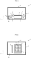
- FIG. 1 is a schematic longitudinal cross-sectional view for depicting a temperature control device of a first embodiment.
- a temperature control device 1 is configured with a housing 2, a temperature control unit 3, a partition plate 25 that partitions the housing 2 into an upper part and a lower part, and an exhaust fan 10.
- An air intake port 4 for introducing outside air is provided on a side surface part of the housing 2 at a predetermined portion located above the partition plate 25.
- the partition plate 25 is provided with an exhaust port 8.
- the exhaust fan 10 is disposed in such a manner as to discharge air from an exhaust path 9 provided below the partition plate 25.
- the temperature control unit 3 includes a temperature adjustment unit 7, a temperature adjustment block 6, and a multi-well plate 5.
- the multi-well plate 5 is disposed above the partition plate 25.
- the temperature adjustment unit 7 and the temperature adjustment block 6 are disposed below the partition plate 25. In other words, the temperature control unit 3 is inserted into the partition plate 25. It should be noted that, in this specification, "temperature adjustment” is an abbreviation of "adjustment of temperature.”
- the outside air introduced from the air intake port 4 passes above the partition plate 25 and the multi-well plate 5 as an airflow 13, passes through the exhaust port 8 and the exhaust path 9, and is discharged to the outside from the exhaust fan 10.
- FIG. 2 is a transverse cross-sectional view for depicting the inside of the temperature control device 1 of FIG. 1 .
- the multi-well plate 5 has a plurality of wells 11. Solutions 12 are dispensed into the respective wells 11. The respective solutions 12 are so held as not to mix with each other.
- the exhaust port 8 has an elongated rectangular shape.
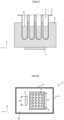
- FIG. 3 is a schematic perspective view for depicting the multi-well plate 5 and the temperature adjustment block 6 of FIG. 2 .
- the multi-well plate 5 is supported by the temperature adjustment block 6.
- Each well 11 is inserted into the temperature adjustment block 6.
- FIG. 4 is a top view for depicting arrangement of the wells 11 in the multi-well plate 5 of FIG. 3 .
- columns are defined in a positive direction of an X-axis and denoted by A, B, C, D, E, F, and G
- rows are defined in a positive direction of a Y-axis and denoted by a, b, c, and d.
- the well 11 in the column A and the row a is expressed as "Aa”
- the well 11 in the column G and the row c is expressed as "Gc.”
- FIG. 5 is a K-K' cross-sectional view of FIG. 4 .
- the wells 11 used as test tubes are formed in the multi-well plate 5.
- the solutions 12 are injected into the respective wells 11.
- the amount of evaporation of the solution 12 can be obtained by the following calculation procedure.
- k [m/s] is a mass transfer coefficient
- Y w [kg/m 3 ] is the amount of saturated steam at the water surface at a liquid temperature T w [°C]
- Y a [kg/m 3 ] is the amount of water vapor of the surrounding air at an air temperature T a [°C] and at humidity HR [%].
- e(T a ) is a saturated water vapor pressure and can be obtained by using the Wagner's equation of saturated water vapor pressure indicated in the following equation (3) .
- e T a 221200 ⁇ exp ⁇ 7.76451 x + 1.45838 x 1.5 ⁇ 2.7758 x 3 ⁇ 1.23303 Dx 6 1 ⁇ x
- D [m 2 /s] is a diffusion coefficient and can be calculated by using a relational expression of Sherwood number Sh that is a dimensionless quantity related to mass transfer expressed by the following equation (4).
- Sc ⁇ ⁇ D
- ⁇ [Pa ⁇ s] is a viscosity coefficient
- ⁇ [kg/m 3 ] is density.
- L [m] is a representative length
- u [m/s] is a wind speed
- an influence of an air flow speed on a water evaporation speed can be quantitatively calculated. That is, when air having no unevenness in temperature and humidity flows above the wells 11 formed in the multi-well plate 5 at a uniform flow speed, the amounts of evaporation Q evap in the respective wells 11 are equal.
- the amount of evaporation from the surface of the solution 12 to the surrounding air increases as the temperature of the flowing air is higher and the flow speed is faster. Meanwhile, the amount of evaporation increases as the humidity of the flowing air is lower.
- the temperature control unit 3 when the temperature control unit 3 is heated to be higher in temperature than the surrounding air, an updraft is generated, and natural convection is generated therearound.
- the air flows in a positive direction of a Z-axis in a central part of the multi-well plate 5. Then, the air flows from an outer peripheral part of the multi-well plate 5 toward the central part.
- the air around the temperature control unit 3 passes above the wells 11 disposed at the outer peripheral part of the multi-well plate 5, and thus the evaporation of the solution 12 is accelerated.
- This increases the humidity of the air that has passed above the wells 11.
- the air with increased humidity flows to the central part of the multi-well plate 5. Since the air flow speed is small above the wells 11 in the central part, the amount of evaporation in the central part is smaller than that in the outer peripheral part.
- the amount of evaporation in the column A is larger than that in the column C due to natural convection.
- the amounts of evaporation in the row a and the row d are larger than those in the row b and the row c.
- the amounts of evaporation are the largest in the corner parts. That is, the amounts of evaporation in the wells Aa, Ad, Ga, and Gd increase, and variations in the amounts of evaporation in the respective wells 11 increase. The amounts of evaporation vary even in the same column A or G.
- the amount of evaporation of the solution 12 is the largest in the row a, the amount of evaporation gradually decreases, and the amount of evaporation is the smallest in the row d.
- the amounts of evaporation of the solutions 12 from the column A to the column G can be made substantially uniform in each of the row a to the row d.
- the air intake port 4 and the exhaust port 8 may each be provided separately at two or more places.
- the multi-well plate 5 is not limited to the structure in which the plurality of wells 11 are integrated, and may be a structure in which a plurality of independent wells 11 are fixed to the temperature adjustment block 6.
- the exhaust air volume by the exhaust fan 10 need not be constant, and the air volume may be changed according to the environmental temperature and environmental humidity.
- the temperature adjustment block 6 is desirably formed of a material having high thermal conductivity, and, for example, an aluminum alloy, a copper alloy, a magnesium alloy, or the like is preferably used.
- the temperature adjustment unit 7 may be configured with a heater, a Peltier element, or a heat pump.
- the width of the exhaust port 8 is made narrower than that of the multi-well plate 5. It should be noted that the descriptions of the configurations denoted by the same symbols and the parts having the same functions described in the first embodiment are omitted.
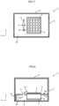
- FIG. 6 is a transverse cross-sectional view for depicting the inside of the temperature control device 1 of a second embodiment.
- a width w2 of the exhaust port 8 in the X-axis direction and a width w1 of the multi-well plate 5 in the X-axis direction are set to satisfy w1 > w2.
- the range in which the flow speed of the airflow 13 (see FIG. 1 ) flowing above the multi-well plate 5 is high is limited to central columns of the multi-well plate 5, and the flow speed above the column B to the column F is faster than that near the column A and the column G.
- the amounts of evaporation in the column B to the column F increase, the difference from the amounts of evaporation in the column A and the column G where the amounts of evaporation increase not only due to the flow from the air intake port 4 but also due to the influence of natural convection is reduced, and variations in the amounts of evaporation in the respective wells 11 of the multi-well plate 5 can be suppressed.
- the width w2 of the exhaust port 8 be made narrower, for example, than the arrangement of the outermost wells 11 in the multi-well plate 5. That is, by making w2 equal to the width ranging from the column B to the column F, it is possible to make the amounts of evaporation in the outermost column A and column G substantially equal to those in the column B to the column F.
- the shape of the exhaust port 8 is changed to a trapezoidal shape. It should be noted that the descriptions of the configurations denoted by the same symbols and the parts having the same functions described in the first and second embodiments are omitted.
- FIG. 7 is a transverse cross-sectional view for depicting the inside of the temperature control device 1 of a third embodiment.
- the exhaust port 8 has a trapezoidal shape in which the width in the X-axis direction becomes smaller toward the positive direction of the Y-axis (the advancing direction of the airflow 13 (see FIG. 1 )).
- a depth h1 in the Y-axis direction in a central part in the X-axis direction and a depth h2 at each end in the X-axis direction are set to satisfy h1 > h2.
- the amounts of evaporation in the column B to the column F increase, the difference from the amounts of evaporation in the column A and the column G where the amounts of evaporation increase not only due to the flow from the air intake port 4 but also due to the influence of natural convection is reduced, and variations in the amounts of evaporation in the respective wells 11 of the multi-well plate 5 can be suppressed.
- the shape of the opening is not limited to the shape that linearly narrows from h1 to h2, and may be a shape in which three or more depths are combined, a shape that narrows in an arc shape, a shape that narrows stepwise, or other shapes.
- two exhaust ports are disposed on the upstream side and the downstream side of the multi-well plate 5. It should be noted that the descriptions of the configurations denoted by the same symbols and the parts having the same functions described in the first to third embodiments are omitted.
- FIG. 8 is a schematic longitudinal cross-sectional view for depicting the temperature control device of a fourth embodiment.
- a front exhaust port 14 is provided between the air intake port 4 and the temperature control unit 3.
- the temperature adjustment unit 7 is not in contact with the bottom of the housing 2. In other words, a gap is provided below the temperature adjustment unit 7.
- the air sucked from the front exhaust port 14 passes through the exhaust path 9 and is discharged to the outside of the housing 2 by the exhaust fan 10.
- Other configurations are the same as those of FIG. 1 .
- FIG. 9 is a transverse cross-sectional view for depicting the inside of the temperature control device 1 of FIG. 8 .
- a depth h3 of the front exhaust port 14 in the Y-axis direction and a depth h4 of the exhaust port 8 in the Y-axis direction are set to satisfy h3 ⁇ h4.
- the airflow 13 flowing in from the air intake port 4 passes above the multi-well plate 5, and variations in the amounts of evaporation of the solutions in the multi-well plate 5 can be suppressed.
- the amount of the airflow 13 passing above the multi-well plate 5 can be limited, it is possible to prevent droplets of the solution from diffusing.
- a duct is provided for the exhaust port. It should be noted that the descriptions of the configurations denoted by the same symbols and the parts having the same functions described in the first to fourth embodiments are omitted.
- Described here is an example of a structure formed up to substantially the same height as the multi-well plate 5. Descriptions will be omitted for the already described configurations denoted by the same symbols and the parts having the same functions.
- FIG. 10 is a schematic longitudinal cross-sectional view for depicting the temperature control device of a fifth embodiment.
- a duct part 15 is provided for the exhaust port 8, and the opening of the exhaust port 8 is set at a height substantially equal to an upper surface of the multi-well plate 5.
- the step between the exhaust port 8 and the upper surface of the multi-well plate 5 can be eliminated, the airflow 13 introduced from the air intake port 4 and passing above the multi-well plate 5 can be sucked into the duct part 15 without curving, the uniformity of the flow above the multi-well plate 5 can be improved, and variations in the amounts of evaporation of the solutions can be suppressed.
- the shape of the duct part 15 is not limited to be substantially the same shape as the exhaust port 8 and may be a circular tube shape or a duct shape narrower than the exhaust port 8.
- a movable lid part is provided such that the width of the exhaust port can be changed. It should be noted that the descriptions of the configurations denoted by the same symbols and the parts having the same functions described in the first to fifth embodiments are omitted.
- FIG. 11 is a schematic longitudinal cross-sectional view for depicting the temperature control device of a sixth embodiment.
- the exhaust port 8 is provided with a movable lid part 16.
- FIG. 12 is a transverse cross-sectional view for depicting the inside of the temperature control device 1 of FIG. 11 .
- the movable lid part 16 is provided at each end of the exhaust port 8 in the width direction (X-axis direction).
- the lid part 16 can change the width of the exhaust port 8 by the opening and closing thereof being controlled.
- by controlling the angle of the lid part 16 not only simple opening and closing but also fine adjustment of flow path resistance can be made.
- temperature control device is applicable to a biochemical device, an analysis device, and a genetic testing device.
Landscapes
- Health & Medical Sciences (AREA)
- Chemical & Material Sciences (AREA)
- Zoology (AREA)
- Wood Science & Technology (AREA)
- Life Sciences & Earth Sciences (AREA)
- Engineering & Computer Science (AREA)
- Bioinformatics & Cheminformatics (AREA)
- Organic Chemistry (AREA)
- Biochemistry (AREA)
- Sustainable Development (AREA)
- General Engineering & Computer Science (AREA)
- Biotechnology (AREA)
- General Health & Medical Sciences (AREA)
- Genetics & Genomics (AREA)
- Biomedical Technology (AREA)
- Microbiology (AREA)
- Clinical Laboratory Science (AREA)
- Thermal Sciences (AREA)
- Analytical Chemistry (AREA)
- Physics & Mathematics (AREA)
- Immunology (AREA)
- Chemical Kinetics & Catalysis (AREA)
- Automatic Analysis And Handling Materials Therefor (AREA)
- Apparatus Associated With Microorganisms And Enzymes (AREA)
Abstract
Description
- The present disclosure relates to a temperature control device and a biochemical device, an analysis device, and a genetic testing device including the same.
- In a fully automatic genetic testing device, extraction of a sample containing DNA (deoxyribonucleic acid), mixing of reagents, amplification of DNA, and inspection are fully automatically performed. In this device, high speed of each operation, improvement of analysis accuracy, and the like are required, and rapid progress in performance has been achieved.
- The fully automatic genetic testing device has a temperature control device that heats a sample and a reagent to a high temperature to facilitate the reaction between the sample and the reagent.
- In the temperature control device, in the case where a solution sample is heated, the solvent evaporates, and the liquid volume changes. When the liquid volume changes, the sample concentration changes, and the analysis accuracy decreases.
-
Patent Document 1 discloses a biochemical processing device that uses a container having a plurality of container parts capable of containing liquid from the viewpoint of preventing liquid evaporation caused by high temperature heating and contamination of the liquid in a plurality of containers, and that has means for selectively sealing the container parts. - In addition,
Patent Document 2 discloses a drying suppressing tool for use in a cell culture kit installed in an incubator in which dust and dirt are suppressed, which has a configuration in which an internal space surrounded by a liquid storage tank and a lid communicates with the outside in a state where the lid is closed, and can suppress water evaporation from a medium held by a well plate. -
- Patent Document 1:
JP-2007-97476-A - Patent Document 2:
JP-2022-2505-A - The biochemical processing device described in
Patent Document 1 has a lid member for the container holding a solution to seal the container, and has a structure for suppressing the amount of evaporation by sealing the container. However, since the lid member and movable means for moving the lid member need to be added, the structure disadvantageously becomes complicated. - In
Patent Document 2, adopted is a structure in which liquid is stored around a container containing a sample solution and the outside air communicates through a section containing the liquid. Accordingly, the periphery of the container becomes humidified atmospheric air, and the amount of evaporation from the container is suppressed. However, there is a problem that the liquid needs to be held around a reaction vessel, and such maintenance as addition or replacement of the liquid is required. - An object of the present disclosure is to reduce variations in the amount of evaporation of a solution held in each of a plurality of wells provided in a multi-well plate.
- A temperature control device of the present disclosure includes a housing, a partition plate that partitions the housing into an upper part and a lower part, a temperature control unit, and an exhaust fan. The temperature control unit includes a temperature adjustment unit and a multi-well plate. The multi-well plate is disposed above the partition plate. The temperature adjustment unit is disposed below the partition plate. An air intake port for introducing outside air is provided on a side surface part of the housing at a predetermined portion located above the partition plate. The partition plate is provided with an exhaust port. The exhaust fan is disposed in such a manner as to discharge air from an exhaust path located below the partition plate to the outside of the housing. The multi-well plate is disposed between the air intake port and the exhaust port. The air flows into the housing from the air intake port, passes above the multi-well plate, and flows into the exhaust path from the exhaust port.
- According to the present disclosure, it is possible to reduce variations in the amount of evaporation of a solution held in each of a plurality of wells provided in a multi-well plate.
-
-
FIG. 1 is a schematic longitudinal cross-sectional view for depicting a temperature control device of a first embodiment. -
FIG. 2 is a transverse cross-sectional view for depicting the inside of atemperature control device 1 ofFIG. 1 . -
FIG. 3 is a schematic perspective view for depicting amulti-well plate 5 and atemperature adjustment block 6 ofFIG. 2 . -
FIG. 4 is a top view for depicting arrangement ofwells 11 in themulti-well plate 5 ofFIG. 3 . -
FIG. 5 is a K-K' cross-sectional view ofFIG. 4 . -
FIG. 6 is a transverse cross-sectional view for depicting the inside of thetemperature control device 1 of a second embodiment. -
FIG. 7 is a transverse cross-sectional view for depicting the inside of thetemperature control device 1 of a third embodiment. -
FIG. 8 is a schematic longitudinal cross-sectional view for depicting the temperature control device of a fourth embodiment. -
FIG. 9 is a transverse cross-sectional view for depicting the inside of thetemperature control device 1 ofFIG. 8 . -
FIG. 10 is a schematic longitudinal cross-sectional view for depicting the temperature control device of a fifth embodiment. -
FIG. 11 is a schematic longitudinal cross-sectional view for depicting the temperature control device of a sixth embodiment. -
FIG. 12 is a transverse cross-sectional view for depicting the inside of thetemperature control device 1 ofFIG. 11 . - Hereinafter, embodiments will be described by using the drawings.
-
FIG. 1 is a schematic longitudinal cross-sectional view for depicting a temperature control device of a first embodiment. - In the drawing, a
temperature control device 1 is configured with ahousing 2, atemperature control unit 3, apartition plate 25 that partitions thehousing 2 into an upper part and a lower part, and anexhaust fan 10. Anair intake port 4 for introducing outside air is provided on a side surface part of thehousing 2 at a predetermined portion located above thepartition plate 25. Thepartition plate 25 is provided with anexhaust port 8. Theexhaust fan 10 is disposed in such a manner as to discharge air from anexhaust path 9 provided below thepartition plate 25. - The
temperature control unit 3 includes atemperature adjustment unit 7, atemperature adjustment block 6, and amulti-well plate 5. Themulti-well plate 5 is disposed above thepartition plate 25. Thetemperature adjustment unit 7 and thetemperature adjustment block 6 are disposed below thepartition plate 25. In other words, thetemperature control unit 3 is inserted into thepartition plate 25. It should be noted that, in this specification, "temperature adjustment" is an abbreviation of "adjustment of temperature." - With the configuration described above, the outside air introduced from the
air intake port 4 passes above thepartition plate 25 and themulti-well plate 5 as anairflow 13, passes through theexhaust port 8 and theexhaust path 9, and is discharged to the outside from theexhaust fan 10. -
FIG. 2 is a transverse cross-sectional view for depicting the inside of thetemperature control device 1 ofFIG. 1 . - As depicted in
FIG. 2 , themulti-well plate 5 has a plurality ofwells 11.Solutions 12 are dispensed into therespective wells 11. Therespective solutions 12 are so held as not to mix with each other. - In the drawing, the
exhaust port 8 has an elongated rectangular shape. -
FIG. 3 is a schematic perspective view for depicting themulti-well plate 5 and thetemperature adjustment block 6 ofFIG. 2 . - As depicted in
FIG. 3 , themulti-well plate 5 is supported by thetemperature adjustment block 6. Each well 11 is inserted into thetemperature adjustment block 6. -
FIG. 4 is a top view for depicting arrangement of thewells 11 in themulti-well plate 5 ofFIG. 3 . - In
FIG. 4 , regarding the arrangement of thewells 11 formed in themulti-well plate 5, columns are defined in a positive direction of an X-axis and denoted by A, B, C, D, E, F, and G, and rows are defined in a positive direction of a Y-axis and denoted by a, b, c, and d. For example, the well 11 in the column A and the row a is expressed as "Aa," and the well 11 in the column G and the row c is expressed as "Gc." -
FIG. 5 is a K-K' cross-sectional view ofFIG. 4 . - As depicted in
FIG. 5 , thewells 11 used as test tubes are formed in themulti-well plate 5. Thesolutions 12 are injected into therespective wells 11. - Here, the amount of evaporation of the
solution 12 can be obtained by the following calculation procedure. - The amount of evaporation Qevap [kg/m3/s] from the surface of the
solution 12 to the surrounding air is obtained by the following equation (1).
[Math. 1]
- Here, k [m/s] is a mass transfer coefficient, Yw [kg/m3] is the amount of saturated steam at the water surface at a liquid temperature Tw [°C], and Ya [kg/m3] is the amount of water vapor of the surrounding air at an air temperature Ta [°C] and at humidity HR [%].
- Yw can be obtained by using the following equation (2).
[Math. 2]
- Here, e(Ta) is a saturated water vapor pressure and can be obtained by using the Wagner's equation of saturated water vapor pressure indicated in the following equation (3) .
[Math. 3]
- Here, D [m2/s] is a diffusion coefficient and can be calculated by using a relational expression of Sherwood number Sh that is a dimensionless quantity related to mass transfer expressed by the following equation (4).
[Math. 4]
- Here, Sc is a Schmidt number and is the ratio of kinematic viscosity and the diffusion coefficient of liquid obtained by the following equation (5).
[Math. 5]
- Note that µ [Pa·s] is a viscosity coefficient, and ρ [kg/m3] is density. In addition, a Reynolds number Re used in the above equation (4) is the ratio of an inertial force and a viscous force obtained in the following equation (6).
[Math. 6]
- Note that L [m] is a representative length, and u [m/s] is a wind speed.
- From these equations, an influence of an air flow speed on a water evaporation speed can be quantitatively calculated. That is, when air having no unevenness in temperature and humidity flows above the
wells 11 formed in themulti-well plate 5 at a uniform flow speed, the amounts of evaporation Qevap in therespective wells 11 are equal. - In addition, the amount of evaporation from the surface of the
solution 12 to the surrounding air increases as the temperature of the flowing air is higher and the flow speed is faster. Meanwhile, the amount of evaporation increases as the humidity of the flowing air is lower. - In general, when the
temperature control unit 3 is heated to be higher in temperature than the surrounding air, an updraft is generated, and natural convection is generated therearound. In the structure of the present embodiment, the air flows in a positive direction of a Z-axis in a central part of themulti-well plate 5. Then, the air flows from an outer peripheral part of themulti-well plate 5 toward the central part. - Accordingly, the air around the
temperature control unit 3 passes above thewells 11 disposed at the outer peripheral part of themulti-well plate 5, and thus the evaporation of thesolution 12 is accelerated. This increases the humidity of the air that has passed above thewells 11. The air with increased humidity flows to the central part of themulti-well plate 5. Since the air flow speed is small above thewells 11 in the central part, the amount of evaporation in the central part is smaller than that in the outer peripheral part. - Described with reference to
FIG. 4 , in the case where no countermeasure is taken, the amount of evaporation in the column A is larger than that in the column C due to natural convection. In addition, the amounts of evaporation in the row a and the row d are larger than those in the row b and the row c. Further, since unhumidified air flows into corner parts of themulti-well plate 5 from both directions of the X-axis direction and the Y-axis direction, the amounts of evaporation are the largest in the corner parts. That is, the amounts of evaporation in the wells Aa, Ad, Ga, and Gd increase, and variations in the amounts of evaporation in therespective wells 11 increase. The amounts of evaporation vary even in the same column A or G. - Meanwhile, in the configuration depicted in
FIG. 1 and FIG. 2 , outside air flows in from theair intake port 4 formed in thehousing 2, and theairflow 13 is generated above themulti-well plate 5. That is, theairflow 13 is generated above thesolutions 12 held in themulti-well plate 5 in the positive direction of the Y-axis (left direction in the drawings). - As a result, as depicted in
FIG. 4 , the amount of evaporation of thesolution 12 is the largest in the row a, the amount of evaporation gradually decreases, and the amount of evaporation is the smallest in the row d. In this case, since no flow in the X-axis direction is generated above themulti-well plate 5, the amounts of evaporation of thesolutions 12 from the column A to the column G can be made substantially uniform in each of the row a to the row d. - By generating the uniform airflow above the container in this manner, it is possible to suppress variations in the amounts of evaporation among the columns. That is, it is possible to suppress variations in the amounts of evaporation in the same row, for example, from Aa to Ga.
- Here, the
air intake port 4 and theexhaust port 8 may each be provided separately at two or more places. In addition, themulti-well plate 5 is not limited to the structure in which the plurality ofwells 11 are integrated, and may be a structure in which a plurality ofindependent wells 11 are fixed to thetemperature adjustment block 6. In addition, the exhaust air volume by theexhaust fan 10 need not be constant, and the air volume may be changed according to the environmental temperature and environmental humidity. Thetemperature adjustment block 6 is desirably formed of a material having high thermal conductivity, and, for example, an aluminum alloy, a copper alloy, a magnesium alloy, or the like is preferably used. - The
temperature adjustment unit 7 may be configured with a heater, a Peltier element, or a heat pump. - In the present embodiment, the width of the
exhaust port 8 is made narrower than that of themulti-well plate 5. It should be noted that the descriptions of the configurations denoted by the same symbols and the parts having the same functions described in the first embodiment are omitted. -
FIG. 6 is a transverse cross-sectional view for depicting the inside of thetemperature control device 1 of a second embodiment. - In the drawing, a width w2 of the
exhaust port 8 in the X-axis direction and a width w1 of themulti-well plate 5 in the X-axis direction are set to satisfy w1 > w2. - By narrowing the width w2 of the
exhaust port 8 in this manner, the range in which the flow speed of the airflow 13 (seeFIG. 1 ) flowing above themulti-well plate 5 is high is limited to central columns of themulti-well plate 5, and the flow speed above the column B to the column F is faster than that near the column A and the column G. As a result, the amounts of evaporation in the column B to the column F increase, the difference from the amounts of evaporation in the column A and the column G where the amounts of evaporation increase not only due to the flow from theair intake port 4 but also due to the influence of natural convection is reduced, and variations in the amounts of evaporation in therespective wells 11 of themulti-well plate 5 can be suppressed. - More specifically, as depicted in the drawing, it is desirable that the width w2 of the
exhaust port 8 be made narrower, for example, than the arrangement of theoutermost wells 11 in themulti-well plate 5. That is, by making w2 equal to the width ranging from the column B to the column F, it is possible to make the amounts of evaporation in the outermost column A and column G substantially equal to those in the column B to the column F. - In the present embodiment, the shape of the
exhaust port 8 is changed to a trapezoidal shape. It should be noted that the descriptions of the configurations denoted by the same symbols and the parts having the same functions described in the first and second embodiments are omitted. -
FIG. 7 is a transverse cross-sectional view for depicting the inside of thetemperature control device 1 of a third embodiment. - In the drawing, the
exhaust port 8 has a trapezoidal shape in which the width in the X-axis direction becomes smaller toward the positive direction of the Y-axis (the advancing direction of the airflow 13 (seeFIG. 1 )). A depth h1 in the Y-axis direction in a central part in the X-axis direction and a depth h2 at each end in the X-axis direction are set to satisfy h1 > h2. - By narrowing the depth h2 of the
exhaust port 8 in this manner, distribution is generated in the flow speeds in theexhaust port 8, and the flow speed is large in the central part of theexhaust port 8 and small at each end of theexhaust port 8. Accordingly, theairflow 13 flowing above themulti-well plate 5 is larger in central columns of themulti-well plate 5, and the flow speed above the column B to the column F is faster than that near the column A and the column G. As a result, the amounts of evaporation in the column B to the column F increase, the difference from the amounts of evaporation in the column A and the column G where the amounts of evaporation increase not only due to the flow from theair intake port 4 but also due to the influence of natural convection is reduced, and variations in the amounts of evaporation in therespective wells 11 of themulti-well plate 5 can be suppressed. - Here, the shape of the opening is not limited to the shape that linearly narrows from h1 to h2, and may be a shape in which three or more depths are combined, a shape that narrows in an arc shape, a shape that narrows stepwise, or other shapes.
- In the present embodiment, two exhaust ports are disposed on the upstream side and the downstream side of the
multi-well plate 5. It should be noted that the descriptions of the configurations denoted by the same symbols and the parts having the same functions described in the first to third embodiments are omitted. -
FIG. 8 is a schematic longitudinal cross-sectional view for depicting the temperature control device of a fourth embodiment. - In the drawing, unlike
FIG. 1 , afront exhaust port 14 is provided between theair intake port 4 and thetemperature control unit 3. In addition, thetemperature adjustment unit 7 is not in contact with the bottom of thehousing 2. In other words, a gap is provided below thetemperature adjustment unit 7. The air sucked from thefront exhaust port 14 passes through theexhaust path 9 and is discharged to the outside of thehousing 2 by theexhaust fan 10. Other configurations are the same as those ofFIG. 1 . -
FIG. 9 is a transverse cross-sectional view for depicting the inside of thetemperature control device 1 ofFIG. 8 . - In
FIG. 9 , a depth h3 of thefront exhaust port 14 in the Y-axis direction and a depth h4 of theexhaust port 8 in the Y-axis direction are set to satisfy h3 < h4. - By narrowing the depth of the
front exhaust port 14 in this manner, pressure loss in thefront exhaust port 14 increases, and the flow speed decreases. - In contrast, since the depth h4 of the
exhaust port 8 is large, the air volume is large, and the flow speed is large. The amount of air sucked from theexhaust port 8 is larger than that exhausted from thefront exhaust port 14. - Therefore, the
airflow 13 flowing in from theair intake port 4 passes above themulti-well plate 5, and variations in the amounts of evaporation of the solutions in themulti-well plate 5 can be suppressed. - In addition, according to the present embodiment, since the amount of the
airflow 13 passing above themulti-well plate 5 can be limited, it is possible to prevent droplets of the solution from diffusing. - In the present embodiment, a duct is provided for the exhaust port. It should be noted that the descriptions of the configurations denoted by the same symbols and the parts having the same functions described in the first to fourth embodiments are omitted.
- Described here is an example of a structure formed up to substantially the same height as the
multi-well plate 5. Descriptions will be omitted for the already described configurations denoted by the same symbols and the parts having the same functions. -
FIG. 10 is a schematic longitudinal cross-sectional view for depicting the temperature control device of a fifth embodiment. - In the drawing, a
duct part 15 is provided for theexhaust port 8, and the opening of theexhaust port 8 is set at a height substantially equal to an upper surface of themulti-well plate 5. - With such a configuration, the step between the
exhaust port 8 and the upper surface of themulti-well plate 5 can be eliminated, theairflow 13 introduced from theair intake port 4 and passing above themulti-well plate 5 can be sucked into theduct part 15 without curving, the uniformity of the flow above themulti-well plate 5 can be improved, and variations in the amounts of evaporation of the solutions can be suppressed. - The shape of the
duct part 15 is not limited to be substantially the same shape as theexhaust port 8 and may be a circular tube shape or a duct shape narrower than theexhaust port 8. - In the present embodiment, a movable lid part is provided such that the width of the exhaust port can be changed. It should be noted that the descriptions of the configurations denoted by the same symbols and the parts having the same functions described in the first to fifth embodiments are omitted.
-
FIG. 11 is a schematic longitudinal cross-sectional view for depicting the temperature control device of a sixth embodiment. - In the drawing, the
exhaust port 8 is provided with amovable lid part 16. -
FIG. 12 is a transverse cross-sectional view for depicting the inside of thetemperature control device 1 ofFIG. 11 . - As depicted in
FIG. 12 , themovable lid part 16 is provided at each end of theexhaust port 8 in the width direction (X-axis direction). Thelid part 16 can change the width of theexhaust port 8 by the opening and closing thereof being controlled. In addition, by controlling the angle of thelid part 16, not only simple opening and closing but also fine adjustment of flow path resistance can be made. - According to the embodiments described above, it is possible to adjust the flow speed distribution of the
airflow 13 above themulti-well plate 5 by adjusting the flow speed in the central part and the flow speed at each end in theexhaust port 8 according to the ambient humidity and the outside air temperature. Accordingly, variations in the amounts of evaporation of thesolutions 12 held in themulti-well plate 5 can be suppressed. - It should be noted that the temperature control device according to the present disclosure is applicable to a biochemical device, an analysis device, and a genetic testing device.
-
- 1:
- Temperature control device
- 2:
- Housing
- 3:
- Temperature control unit
- 4:
- Air intake port
- 5:
- Multi-well plate
- 6:
- Temperature adjustment block
- 7:
- Temperature adjustment unit
- 8:
- Exhaust port
- 9:
- Exhaust path
- 10:
- Exhaust fan
- 11:
- Well
- 12:
- Solution
- 13:
- Airflow
- 14:
- Front exhaust port
- 15:
- Duct part
- 16:
- Lid part
- 25:
- Partition plate
Claims (9)
- A temperature control device comprising:a housing;a partition plate that partitions the housing into an upper part and a lower part;a temperature control unit; andan exhaust fan,wherein the temperature control unit includes a temperature adjustment unit and a multi-well plate,the multi-well plate is disposed above the partition plate,the temperature adjustment unit is disposed below the partition plate,an air intake port for introducing outside air is provided on a side surface part of the housing at a predetermined portion located above the partition plate,the partition plate is provided with an exhaust port,the exhaust fan is disposed in such a manner as to discharge air from an exhaust path located below the partition plate to an outside of the housing,the multi-well plate is disposed between the air intake port and the exhaust port, andthe air flows into the housing from the air intake port, passes above the multi-well plate, and flows into the exhaust path from the exhaust port.
- The temperature control device according to claim 1,
wherein a width of the exhaust port is narrower than that of the multi-well plate. - The temperature control device according to claim 1,
wherein a width of the exhaust port is narrowed toward an advancing direction of the air. - The temperature control device according to claim 1,wherein a front exhaust port is provided between the air intake port and the multi-well plate, andthe front exhaust port is narrower in depth than the exhaust port.
- The temperature control device according to claim 1,wherein the exhaust port is provided with a duct part, andan opening of the exhaust port is disposed at a height substantially equal to an upper surface of the multi-well plate.
- The temperature control device according to claim 1,
wherein the exhaust port is provided with a movable lid part. - A biochemical device comprising:
the temperature control device according to any one of claims 1 to 6. - An analysis device comprising:
the temperature control device according to any one of claims 1 to 6. - A genetic testing device comprising:
the temperature control device according to any one of claims 1 to 6.
Applications Claiming Priority (1)
| Application Number | Priority Date | Filing Date | Title |
|---|---|---|---|
| PCT/JP2022/030360 WO2024033994A1 (en) | 2022-08-09 | 2022-08-09 | Temperature control device and biochemical device, analysis device, and genetic testing device comprising same |
Publications (2)
| Publication Number | Publication Date |
|---|---|
| EP4570897A1 true EP4570897A1 (en) | 2025-06-18 |
| EP4570897A4 EP4570897A4 (en) | 2026-06-10 |
Family
ID=89851193
Family Applications (1)
| Application Number | Title | Priority Date | Filing Date |
|---|---|---|---|
| EP22954916.7A Pending EP4570897A4 (en) | 2022-08-09 | 2022-08-09 | TEMPERATURE CONTROL DEVICE AND BIOCHEMICAL DEVICE, ANALYSIS DEVICE AND GENETIC TESTING DEVICE WITH IT |
Country Status (6)
| Country | Link |
|---|---|
| EP (1) | EP4570897A4 (en) |
| JP (1) | JP7735579B2 (en) |
| KR (1) | KR20240160139A (en) |
| CN (1) | CN119032158A (en) |
| TW (1) | TWI842585B (en) |
| WO (1) | WO2024033994A1 (en) |
Family Cites Families (14)
| Publication number | Priority date | Publication date | Assignee | Title |
|---|---|---|---|---|
| JP4682008B2 (en) | 2005-10-04 | 2011-05-11 | キヤノン株式会社 | Biochemical treatment equipment, containers and inspection equipment used therefor |
| JP2014518758A (en) * | 2011-05-06 | 2014-08-07 | バイオ−ラッド ラボラトリーズ インコーポレーティッド | Thermal cycler with vapor chamber for rapid temperature changes |
| US10725059B2 (en) * | 2015-04-06 | 2020-07-28 | Meso Scale Technologies, Llc. | High throughput system for performing assays using electrochemiluminescence including a consumable shaking apparatus |
| JP2017108710A (en) * | 2015-12-18 | 2017-06-22 | ウシオ電機株式会社 | Sample heating apparatus |
| JP3203237U (en) * | 2016-01-07 | 2016-03-17 | サーモジェン有限会社 | Portable DNA amplification device |
| CN205511214U (en) * | 2016-01-27 | 2016-08-31 | 济南科益试验设备有限公司 | Artificial intelligence weather case with new wind circulation system |
| US12655375B2 (en) * | 2018-05-18 | 2026-06-16 | Huacells Corporation | Automated cell culturing |
| US11378496B2 (en) * | 2018-06-18 | 2022-07-05 | Shimadzu Corporation | Device with sample temperature adjustment function |
| EP3899032A2 (en) * | 2018-12-20 | 2021-10-27 | Omniome, Inc. | Temperature control for analysis of nucleic acids and other analytes |
| US20210284947A1 (en) * | 2020-03-12 | 2021-09-16 | Ricoh Company, Ltd. | Drying suppression device and cell culture kit |
| JP7669701B2 (en) | 2020-03-12 | 2025-04-30 | 株式会社リコー | Drying prevention equipment and cell culture kit |
| WO2022003915A1 (en) * | 2020-07-02 | 2022-01-06 | 株式会社日立ハイテク | Cassette stand, reaction unit and genetic testing device |
| JP7499340B2 (en) * | 2020-08-31 | 2024-06-13 | 株式会社日立ハイテク | Biochemical analyzer, reaction unit and cassette guide |
| CN215050313U (en) * | 2021-03-01 | 2021-12-07 | 贵州北科生物科技有限公司 | PCR device |
-
2022
- 2022-08-09 JP JP2024540104A patent/JP7735579B2/en active Active
- 2022-08-09 WO PCT/JP2022/030360 patent/WO2024033994A1/en not_active Ceased
- 2022-08-09 KR KR1020247032424A patent/KR20240160139A/en active Pending
- 2022-08-09 CN CN202280094754.0A patent/CN119032158A/en active Pending
- 2022-08-09 EP EP22954916.7A patent/EP4570897A4/en active Pending
-
2023
- 2023-07-06 TW TW112125263A patent/TWI842585B/en active
Also Published As
| Publication number | Publication date |
|---|---|
| JPWO2024033994A1 (en) | 2024-02-15 |
| JP7735579B2 (en) | 2025-09-08 |
| KR20240160139A (en) | 2024-11-08 |
| TWI842585B (en) | 2024-05-11 |
| WO2024033994A1 (en) | 2024-02-15 |
| TW202407094A (en) | 2024-02-16 |
| EP4570897A4 (en) | 2026-06-10 |
| CN119032158A (en) | 2024-11-26 |
Similar Documents
| Publication | Publication Date | Title |
|---|---|---|
| CN103402641B (en) | For processing liquid or the apparatus and method of material based on liquid | |
| Berthier et al. | Managing evaporation for more robust microscale assays: Part 1. Volume loss in high throughput assays | |
| Chen et al. | Centrifugal micro-channel array droplet generation for highly parallel digital PCR | |
| US10092900B2 (en) | Plurality of reaction chambers in a test cartridge | |
| US8900854B2 (en) | Liquid reflux high-speed gene amplification device | |
| US8475626B2 (en) | Multiple connected channel micro evaporator | |
| CN104531519B (en) | A kind of micro-fluidic detection chip tested based on droplet | |
| US20060199261A1 (en) | Holder and method for cooling or heating samples | |
| US11478791B2 (en) | Flow control and processing cartridge | |
| CN101696916A (en) | Device for analyzing and sieving liquid drops based on integrative sampling probe of chip | |
| US20120301367A1 (en) | Reaction vessel | |
| WO2005095576A2 (en) | Controlled temperature water (or other fluid)-jacket co2 microscope stage incubator | |
| Nakashoji et al. | A poly (dimethylsiloxane) microfluidic sheet reversibly adhered on a glass plate for creation of emulsion droplets for droplet digital PCR | |
| JP7735579B2 (en) | Temperature control device, and biochemical device, analytical device, and genetic testing device equipped with the same | |
| US20200239821A1 (en) | Microfluidic perfusion cell culture system | |
| WO2015127277A1 (en) | Method for guiding cell spreading in automated cytogenetic assays | |
| JP2014092420A (en) | Processing chip for biochemical reaction analysis | |
| CN111389474A (en) | A microfluidic chip for sample dispersion and its preparation method and application | |
| WO2011139976A1 (en) | Cell staining with air quenched steam heating | |
| US20230194468A1 (en) | Measuring system | |
| CN107709959B (en) | Method for evaporating liquid in microcapillary | |
| Zhu et al. | Evaluation of microfluidics‐based droplet PCR combined with multiplex STR system in forensic science | |
| CN115916946A (en) | Cassette racks, reaction units and genetic testing devices | |
| CN109174217B (en) | Microfluidic chip and method for realizing drying process in synthesis reaction | |
| JP4944603B2 (en) | Biochemical reaction vessel |
Legal Events
| Date | Code | Title | Description |
|---|---|---|---|
| STAA | Information on the status of an ep patent application or granted ep patent |
Free format text: STATUS: THE INTERNATIONAL PUBLICATION HAS BEEN MADE |
|
| PUAI | Public reference made under article 153(3) epc to a published international application that has entered the european phase |
Free format text: ORIGINAL CODE: 0009012 |
|
| STAA | Information on the status of an ep patent application or granted ep patent |
Free format text: STATUS: REQUEST FOR EXAMINATION WAS MADE |
|
| 17P | Request for examination filed |
Effective date: 20241031 |
|
| AK | Designated contracting states |
Kind code of ref document: A1 Designated state(s): AL AT BE BG CH CY CZ DE DK EE ES FI FR GB GR HR HU IE IS IT LI LT LU LV MC MK MT NL NO PL PT RO RS SE SI SK SM TR |
|
| DAV | Request for validation of the european patent (deleted) | ||
| DAX | Request for extension of the european patent (deleted) | ||
| A4 | Supplementary search report drawn up and despatched |
Effective date: 20260511 |
|
| RIC1 | Information provided on ipc code assigned before grant |
Ipc: C12M 1/00 20060101AFI20260504BHEP Ipc: B01L 7/00 20060101ALI20260504BHEP Ipc: C12M 1/32 20060101ALI20260504BHEP |