EP4570731A1 - Step of passenger conveyor and passenger conveyor - Google Patents
Step of passenger conveyor and passenger conveyor Download PDFInfo
- Publication number
- EP4570731A1 EP4570731A1 EP24217589.1A EP24217589A EP4570731A1 EP 4570731 A1 EP4570731 A1 EP 4570731A1 EP 24217589 A EP24217589 A EP 24217589A EP 4570731 A1 EP4570731 A1 EP 4570731A1
- Authority
- EP
- European Patent Office
- Prior art keywords
- guide rail
- passenger conveyor
- jump
- step guide
- conveyor according
- Prior art date
- Legal status (The legal status is an assumption and is not a legal conclusion. Google has not performed a legal analysis and makes no representation as to the accuracy of the status listed.)
- Pending
Links
Images




Classifications
-
- B—PERFORMING OPERATIONS; TRANSPORTING
- B66—HOISTING; LIFTING; HAULING
- B66B—ELEVATORS; ESCALATORS OR MOVING WALKWAYS
- B66B23/00—Component parts of escalators or moving walkways
- B66B23/08—Carrying surfaces
- B66B23/12—Steps
-
- B—PERFORMING OPERATIONS; TRANSPORTING
- B66—HOISTING; LIFTING; HAULING
- B66B—ELEVATORS; ESCALATORS OR MOVING WALKWAYS
- B66B21/00—Kinds or types of escalators or moving walkways
- B66B21/02—Escalators
- B66B21/04—Escalators linear type
-
- B—PERFORMING OPERATIONS; TRANSPORTING
- B66—HOISTING; LIFTING; HAULING
- B66B—ELEVATORS; ESCALATORS OR MOVING WALKWAYS
- B66B23/00—Component parts of escalators or moving walkways
- B66B23/14—Guiding means for carrying surfaces
Definitions
- the present disclosure relates to a conveying system, in particular to a step of a passenger conveyor and a passenger conveyor.
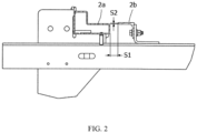
- FIGS. 1 and 2 The local structure of an existing passenger conveyor is shown in FIGS. 1 and 2 , in which parts such as a step 1a and a step track 2a are shown.
- an independent emergency track 2b and corresponding support structures are usually arranged near the step track 2a, and step hooks 1b are installed on the step 1a.
- step 1a When the step 1a encounters certain situations, it may jump upward and move due to malfunction.
- FIG. 2 exemplarily illustrates that the horizontal gap S1 and the vertical gap S2 between the emergency track 2b and the step track 2a need to meet the application requirements after assembly.
- the present disclosure provides a step of a passenger conveyor and a passenger conveyor, so as to solve or at least alleviate one or more of the aforementioned problems and other problems in the prior art, or to provide alternative technical solutions for the prior art.
- a step of a passenger conveyor is firstly provided, wherein the step is provided with a step anti-jump member, the step anti-jump member comprising:
- Particular embodiments further may include at least one, or a plurality of, the following optional features, alone or in combination with each other:
- the step anti-jump member is provided below a roller shaft seat located on both sides of the step, the first portion is perpendicular to an axis of roller of the step, and the second portion is parallel to the axis.
- the second portion is arranged below a rail surface of the step guide rail and is provided with a protrusion which comes into contact with the step guide rail when the upward jump displacement of the step exceeds the preset value and is configured to have a gradually decreasing cross-sectional area in a direction facing and perpendicular to the rail surface.
- a top of the protrusion is configured into a circular arc shape, and a yield strength of the protrusion is not greater than a yield strength of the step guide rail.
- a part of the second portion that extends below the rail surface is not less than half of a length of the second portion.
- the first portion and/or the second portion are provided with a reinforcing rib structure, and/or the first portion is integrally formed with the second portion, and/or the first portion, the second portion and the frame of the step are integrally formed.
- the preset gaps between the second portion and the step guide rail include a horizontal gap and a vertical gap, and the horizontal gap is within a range of 7-10mm and the vertical gap is within a range of 5-8mm.
- a passenger conveyor comprising:
- Particular embodiments further may include at least one, or a plurality of, the following optional features, alone or in combination with each other:
- the rail surface of the step guide rail has an extension portion extending horizontally towards the step anti-jump member and a groove portion located below the extension portion, and a part of the second portion is arranged within the groove portion.
- the step guide rail is a sheet metal bending member, and the step guide rail has a thickness range of 4-6 mm and the groove portion has a depth range of 12-18 mm.
- the solutions of the disclosure innovatively improve the structures of the step and the step guide rail of a passenger conveyor, which eliminates the configuration of additional emergency track in the system. This not only saves materials and manpower investment, but also improves the on-site installation efficiency of the passenger conveyor and reduces construction difficulty.
- the possibility of failure of the passenger conveyor during operation due to human installation errors, loosening or deformation of connecting parts of original emergency track, etc. can be significantly reduced, thereby improving the safety performance of the passenger conveyor.
- FIG. 3 illustrates an escalator 10. It should become apparent in the ensuing description that the present disclosure is applicable to other passenger conveyors, such as moving walks.
- the escalator 10 generally includes a truss 12 extending between a lower landing 14 and an upper landing 16, wherein the truss 12 is fixedly installed on site.
- a plurality of sequentially connected steps or tread plates 18 are connected to a step chain 20 and travel through a closed loop path within the truss 12 along a guide rail 23 fixedly connected onto the truss, thus forming a conveying section for carrying passengers.
- a pair of balustrades 22 includes moving handrails 24.
- a drive machine 26, or drive system is typically located in a machine space 28 under the upper landing 16.
- the drive machine 26 is configured to drive the steps 18 and/or handrails 24 through the step chain 20.
- the drive machine 26 operates to move the tread plates 18 in a chosen direction at a desired speed under normal operating conditions.
- the steps 18 make a 180 degree heading change in a turn-around area 19 located under the lower landing 14 and upper landing 16.
- the steps 18 are pivotally attached to the step chain 20 and follow a closed loop path of the step chain 20, running from one landing to the other, and back again.
- the drive machine 26 includes a first drive member 32, such as motor output sheave, connected to a drive motor 34 through a belt reduction assembly 36 including a second drive member 38, such as an output sheave, driven by a drive chain 39, such as an output belt.
- the first drive member 32 in some embodiments is a driving member, and the second drive member 38 is a driven member.
- the first drive member 32 and/or the second drive member 38 may be any type of rotational device, such as a sheave, pulley, gear, wheel, sprocket, cog, pinion, etc.
- the drive chain 39 in various embodiments, may be configured as a chain, belt, cable, ribbon, band, strip, or any other similar device that operatively connects two elements to provide a driving force from one element to another.
- the drive chain 39 may be any type of interconnecting member that extends between and operatively connects the first drive member 32 and a second drive member 38.
- the first drive member 32 and the second drive member may provide a belt reduction.
- first drive member 32 may be approximately 75 mm (2.95 inches) in diameter while the second drive member 38 may be approximately 750 mm (29.53 inches) in diameter.
- the belt reduction allows the replacement of sheaves to change the speed for 50 or 60 Hz electrical supply power applications, or different step speeds.
- the second drive member 38 may be substantially similar to the first drive member 32.
- the first drive member 32 is driven by drive motor 34 and thus is configured to drive the drive chain 39 and the second drive member 38.
- the second drive member 38 may be an idle gear or similar device that is driven by the operative connection between the first drive member 32 and the second drive member 38 by means of drive chain 39.
- the drive chain 39 travels around a loop set by the first drive member 32 and the second drive member 38, which hereinafter may be referred to as a small loop.
- the small loop is provided for driving a larger loop which consists of the step chain 20, and is driven by an output sheave 40, for example. Under normal operating conditions, the drive chain 39 and the step chain 20 move in unison, based upon the speed of movement of the first drive member 32 as driven by the drive motor 34.
- the escalator 10 also includes a controller 115 that is in electronic communication with the drive motor 34.
- the controller 115 may be located, as shown, in the machine space 28 of the escalator 10 and is configured to control the operation of the escalator 10.
- the controller 115 may provide drive signals to the drive motor 34 to control the acceleration, deceleration, stopping, etc. of the steps 18 through the step chain 20.
- the controller 115 may be an electronic controller including a processor and an associated memory comprising computer-executable instructions that, when executed by the processor, cause the processor to perform various operations.
- the processor may be, but is not limited to, a single-processor or multi-processor system of any of a wide array of possible architectures, including field programmable gate array (FPGA), central processing unit (CPU), application specific integrated circuits (ASIC), digital signal processor (DSP) or graphics processing unit (GPU) hardware arranged homogenously or heterogeneously.
- the memory may be but is not limited to a random access memory (RAM), read only memory (ROM), or other electronic, optical, magnetic or any other computer readable medium.
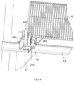
- step anti-jump members 50 can be configured on one or more steps 18 of the escalator 10 according to application needs, so that it is not necessary to install an additional emergency track separately in escalator 10 as in the prior art shown in FIG. 1 .
- the function of the emergency track will be integrated into the step tracks 23, which will effectively save costs in terms of materials, manpower, etc., reduce the difficulty of on-site installation and maintenance operations, and improve efficiency. It can also improve the operational reliability of the step tracks and the steps.
- the step anti-jump member 50 may include a first portion 51 and a second portion 52, both of which may use the same or different materials such as both using materials such as aluminum alloy or cast iron.
- the first portion 51 and the second portion 52 can be manufactured separately, and then connected together using techniques such as welding.
- the first portion 51 and the second portion 52 can also be integrally formed.
- the first portion 51 and the second portion 52 can be integrally formed into a configuration that meets the design requirements through die casting using suitable materials such as die cast aluminum alloy YL102.
- the present disclosure allows the first portion 51 and second portion 52 of the step anti-jump member 50 to be integrally formed with the frame of the step 18 to form an overall structure, so as to improve structural reliability and facilitate installation and maintenance.
- the first portion 51 or the second portion 52 can be provided with structures such as reinforcing ribs as needed to further enhance the mechanical structural performance of the step anti-jump members.
- the first portion 51 of the step anti-jump member 50 is connected to the frame of the step 18.
- the first portion 51 of the step anti-jump member 50 can be installed and connected below the roller shaft seat 182 for supporting the roller 181 located on both sides of the step 18.
- the first portion 51 and the axis of the roller 181 can be made in a substantially perpendicular relationship
- the second portion 52 and the axis of the roller 181 can be made in a substantially parallel relationship.
- the second portion 52 of the step anti-jump member 50 is configured to extend towards the step guide rail 23. After connecting these steps 18 to form a closed loop through the step chain 20 and assembling them in place in the escalator 10, preset gaps can be maintained between the second portion 52 and the step guide rail 23 as needed. That is, the above gaps can be designed, configured, and adjusted according to specific application requirements.
- the horizontal gap between the second portion 52 and the step guide rail 23 can be configured to be within the range of 7-10mm, and the vertical gap between them can be configured to be within the range of 5-8mm.
- the horizontal gap and vertical gap can be controlled to 8mm and 6mm respectively after assembly, and so on.
- step 18 When powered by the drive machine 26, the step 18 will be driven along with the step chain 20 to move along the step guide rail 23.
- abnormal situations such as the roller 181 or roller 180 of the step 18 (which are embodied as as secondary and main wheels in the given example) being blocked by foreign objects, such as the roller encountering small stones, small objects dropped by passengers on the tracks, etc., it will cause step 18 to jump upward and the upward displacement may exceed the preset value (which can be configured as needed and corresponds to the aforementioned vertical gap).
- the second portion 52 of the step anti-jump member 50 will also move upwards, and then comes into contact with the step guide rail 23 to be obstructed by the latter, so that the step 18 can be limited from continuing to jump up, so as to avoid possible damages to components such as the step 18, thus playing a role of step anti-jump protection, and effectively ensuring the safe operation of the system.
- the step guide rail 23 and the step anti-jump member 50 can be arranged adjacent to each other, and the rail surface 231 of the step guide rail 23 can be configured to extend horizontally towards the step anti-jump member 50 to form an extension portion 232.
- the extension portion 232 By use of the extension portion 232, a groove portion 233 located below it is formed, as shown schematically in FIG. 5 and other figures.
- a part of the second portion 52 can be arranged within the space formed by the groove portion 233.
- the length of this portion can be selected to be not less than half of the length of the second portion 52, so that in the event of a step jump-up, a relatively large contact area can be formed by moving the above portion upwards to rest against underneath the rail surface 231 of the step guide rail 23, so as to achieve a better effect of limiting the continued jump up and movement of the step 18.
- the step guide rail 23 can be formed using sheet metal parts by means of bending processing technology.
- the material used, thickness, length, and other aspects of the step guide rail 23 can be configured as needed.
- the thickness can be configured within the range of 4-6 mm
- the depth of the groove 233 can be configured within the range of 12-18 mm, and so on.
- the present disclosure does not make specific restrictions in this regard.
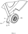
- a protrusion 53 can be provided on the second portion 52 of the step anti-jump member 50.
- such protrusions 53 can be used to make contact with the step guide rail 23, so that the contact limit operation between the step anti-jump member 50 and the step guide rail 23 can be controlled through the contact parts, contact forces, material wear, etc. that meet specific expectations, and a better step anti-jump protection effect that meets actual requirements can be achieved.
- the protrusion 53 can be configured to have a gradually decreasing cross-sectional area in the vertical direction facing the rail surface 231 of the step guide rail 23, such as a roughly " " shaped configuration as shown in FIG. 7 .
- the top of the protrusion 53 can be constructed into a circular arc shape to reduce the possible impacts on impact, noise, and other aspects when the step anti-jump member 50 and the step guide rail 23 come into contact.
- the protrusion 53 can be configured so that its yield strength is not greater than that of the step guide rail 23, so as to better protect the relatively more important step guide rail 23. For example, in the case of using material Q235B for the step guide rail 23 and material YL102 for step anti-jump member 50, the yield strength of the latter can be roughly half of the former.
- emergency tracks widely configured and used in existing equipment can be eliminated in the passenger conveyor, while the step anti-jump function is integrated into the conventional step guide rail used in combination with the step anti-jump member.
- steps, step chains, step guide rails, etc. installed with the anti-jump members as long as they meet the requirements of product design and production, only routine operations are required during assembly.
- This therefore, eliminates the need for tedious installation and adjustment operations between emergency tracks, step guide rails, steps, etc., as in existing technical solutions, which can greatly save manpower and material costs, significantly reduce the possibility of equipment failures caused by human caused installation errors, loose connections or deformation of the emergency tracks and other factors in the existing emergency track installation process, thereby enhancing the safety and reliability of the passenger conveyor.
Landscapes
- Escalators And Moving Walkways (AREA)
Abstract
Description
- The present disclosure relates to a conveying system, in particular to a step of a passenger conveyor and a passenger conveyor.
- At present, passenger conveyor systems such as escalators and moving walks have been widely used in many places, which bring great convenience to people's work, production, and travel. The local structure of an existing passenger conveyor is shown in
FIGS. 1 and2 , in which parts such as a step 1a and astep track 2a are shown. For safety reasons, anindependent emergency track 2b and corresponding support structures are usually arranged near thestep track 2a, andstep hooks 1b are installed on the step 1a. During the operation of the passenger conveyor, when the step 1a encounters certain situations, it may jump upward and move due to malfunction. At this point, thestep hooks 1b installed on the step 1a are blocked by theemergency tracks 2b, so as to prevent the step 1a from continuing to jump upward and avoid the step thrust force being too large, playing the function of anti-jump protection of the step. In order to ensure the reliable operation of theseemergency tracks 2b, it is necessary to repeatedly adjust and confirm the positioning and structural dimensions of relevant components during installation and maintenance. For example,FIG. 2 exemplarily illustrates that the horizontal gap S1 and the vertical gap S2 between theemergency track 2b and thestep track 2a need to meet the application requirements after assembly. - In view of the foregoing, the present disclosure provides a step of a passenger conveyor and a passenger conveyor, so as to solve or at least alleviate one or more of the aforementioned problems and other problems in the prior art, or to provide alternative technical solutions for the prior art.
- According to one aspect of the present disclosure, a step of a passenger conveyor is firstly provided, wherein the step is provided with a step anti-jump member, the step anti-jump member comprising:
- a first portion connected to a frame of the step; and
- a second portion connected to the first portion and extending towards a step guide rail, wherein after a plurality of steps are connected by a step chain and assembled in place on the step guide rail, preset gaps are maintained between the second portion and the step guide rail, and when an upward jump displacement of the step exceeds a preset value during a travelling of the step along the step guide rail, the second portion comes into contact with the step guide rail to limit the step from continuing to jump upward.
- Particular embodiments further may include at least one, or a plurality of, the following optional features, alone or in combination with each other:
- In a step of a passenger conveyor according to the present disclosure, optionally, the step anti-jump member is provided below a roller shaft seat located on both sides of the step, the first portion is perpendicular to an axis of roller of the step, and the second portion is parallel to the axis.
- In a step of a passenger conveyor according to the present disclosure, optionally, the second portion is arranged below a rail surface of the step guide rail and is provided with a protrusion which comes into contact with the step guide rail when the upward jump displacement of the step exceeds the preset value and is configured to have a gradually decreasing cross-sectional area in a direction facing and perpendicular to the rail surface.
- In a step of a passenger conveyor according to the present disclosure, optionally, a top of the protrusion is configured into a circular arc shape, and a yield strength of the protrusion is not greater than a yield strength of the step guide rail.
- In a step of a passenger conveyor according to the present disclosure, optionally, a part of the second portion that extends below the rail surface is not less than half of a length of the second portion.
- In a step of a passenger conveyor according to the present disclosure, optionally, the first portion and/or the second portion are provided with a reinforcing rib structure, and/or the first portion is integrally formed with the second portion, and/or the first portion, the second portion and the frame of the step are integrally formed.
- In a step of a passenger conveyor according to the present disclosure, optionally, the preset gaps between the second portion and the step guide rail include a horizontal gap and a vertical gap, and the horizontal gap is within a range of 7-10mm and the vertical gap is within a range of 5-8mm.
- In addition, according to another aspect of the present disclosure, a passenger conveyor is further provided, comprising:
- a truss fixed and installed on site;
- a step guide rail installed on the truss; and
- a plurality of steps of a passenger conveyor according to any of the above, connected by a step chain and assembled on the step guide rail, wherein the second portion of the step anti-jump member maintains preset gaps with the step guide rail, and comes into contact with the step guide rail to limit the step from continuing to jump upward when an upward jump displacement of the step exceeds a preset value during a travelling of the step along the step guide rail.
- Particular embodiments further may include at least one, or a plurality of, the following optional features, alone or in combination with each other:
- In a passenger conveyor according to the present disclosure, optionally, the rail surface of the step guide rail has an extension portion extending horizontally towards the step anti-jump member and a groove portion located below the extension portion, and a part of the second portion is arranged within the groove portion.
- In a passenger conveyor according to the present disclosure, optionally, the step guide rail is a sheet metal bending member, and the step guide rail has a thickness range of 4-6 mm and the groove portion has a depth range of 12-18 mm.
- The solutions of the disclosure innovatively improve the structures of the step and the step guide rail of a passenger conveyor, which eliminates the configuration of additional emergency track in the system. This not only saves materials and manpower investment, but also improves the on-site installation efficiency of the passenger conveyor and reduces construction difficulty. By adopting the solutions of the disclosure, the possibility of failure of the passenger conveyor during operation due to human installation errors, loosening or deformation of connecting parts of original emergency track, etc., can be significantly reduced, thereby improving the safety performance of the passenger conveyor.
- The technical solutions of the present disclosure will be described in further detail below with reference to the accompanying drawings and embodiments. However, it should be understood that these drawings are designed merely for the purpose of explanation and only intended to conceptually illustrate the structures and configurations described herein, and are not required to be drawn to scale.
-
FIG. 1 is a local three-dimensional structural schematic diagram of a step, an adjacent step track, an emergency track, and a truss in an existing passenger conveyor. -
FIG. 2 is a side-view structural schematic diagram of the step track, emergency track, and truss in the existing passenger conveyor shown inFIG. 1 . -
FIG. 3 is a three-dimensional structural schematic diagram of an embodiment of an escalator according to the present disclosure. -
FIG. 4 is a local three-dimensional structural schematic diagram of a step, an adjacent step track, and a truss in the embodiment of an escalator shown inFIG. 3 . -
FIG. 5 is another local three-dimensional structural schematic diagram of the step, adjacent step track, and truss shown inFIG. 4 . -
FIG. 6 is a side-view structural schematic diagram of the step, adjacent step track, and truss shown inFIG. 4 . -
FIG. 7 is a local three-dimensional structural schematic diagram of a step in the embodiment of an escalator shown inFIG. 3 . -
FIG. 8 is another local three-dimensional structural schematic diagram of a step in the embodiment of an escalator shown inFIG. 3 . -
FIG. 3 illustrates anescalator 10. It should become apparent in the ensuing description that the present disclosure is applicable to other passenger conveyors, such as moving walks. Theescalator 10 generally includes atruss 12 extending between alower landing 14 and an upper landing 16, wherein thetruss 12 is fixedly installed on site. A plurality of sequentially connected steps ortread plates 18 are connected to astep chain 20 and travel through a closed loop path within thetruss 12 along aguide rail 23 fixedly connected onto the truss, thus forming a conveying section for carrying passengers. A pair ofbalustrades 22 includes movinghandrails 24. Adrive machine 26, or drive system, is typically located in amachine space 28 under the upper landing 16. However, an additional machine space 28' may be located under thelower landing 14. Thedrive machine 26 is configured to drive thesteps 18 and/orhandrails 24 through thestep chain 20. Thedrive machine 26 operates to move thetread plates 18 in a chosen direction at a desired speed under normal operating conditions. - The
steps 18 make a 180 degree heading change in a turn-aroundarea 19 located under thelower landing 14 and upper landing 16. Thesteps 18 are pivotally attached to thestep chain 20 and follow a closed loop path of thestep chain 20, running from one landing to the other, and back again. - The
drive machine 26 includes a first drive member 32, such as motor output sheave, connected to adrive motor 34 through a belt reduction assembly 36 including asecond drive member 38, such as an output sheave, driven by adrive chain 39, such as an output belt. The first drive member 32 in some embodiments is a driving member, and thesecond drive member 38 is a driven member. - As used herein, the first drive member 32 and/or the
second drive member 38, in various embodiments, may be any type of rotational device, such as a sheave, pulley, gear, wheel, sprocket, cog, pinion, etc. Thedrive chain 39, in various embodiments, may be configured as a chain, belt, cable, ribbon, band, strip, or any other similar device that operatively connects two elements to provide a driving force from one element to another. For example, thedrive chain 39 may be any type of interconnecting member that extends between and operatively connects the first drive member 32 and asecond drive member 38. In some embodiments, as shown inFIG. 1 , the first drive member 32 and the second drive member may provide a belt reduction. For example, first drive member 32 may be approximately 75 mm (2.95 inches) in diameter while thesecond drive member 38 may be approximately 750 mm (29.53 inches) in diameter. The belt reduction, for example, allows the replacement of sheaves to change the speed for 50 or 60 Hz electrical supply power applications, or different step speeds. However, in other embodiments, thesecond drive member 38 may be substantially similar to the first drive member 32. - As noted, the first drive member 32 is driven by drive
motor 34 and thus is configured to drive thedrive chain 39 and thesecond drive member 38. In some embodiments, thesecond drive member 38 may be an idle gear or similar device that is driven by the operative connection between the first drive member 32 and thesecond drive member 38 by means ofdrive chain 39. Thedrive chain 39 travels around a loop set by the first drive member 32 and thesecond drive member 38, which hereinafter may be referred to as a small loop. The small loop is provided for driving a larger loop which consists of thestep chain 20, and is driven by anoutput sheave 40, for example. Under normal operating conditions, thedrive chain 39 and thestep chain 20 move in unison, based upon the speed of movement of the first drive member 32 as driven by thedrive motor 34. - The
escalator 10 also includes acontroller 115 that is in electronic communication with thedrive motor 34. Thecontroller 115 may be located, as shown, in themachine space 28 of theescalator 10 and is configured to control the operation of theescalator 10. For example, thecontroller 115 may provide drive signals to thedrive motor 34 to control the acceleration, deceleration, stopping, etc. of thesteps 18 through thestep chain 20. Thecontroller 115 may be an electronic controller including a processor and an associated memory comprising computer-executable instructions that, when executed by the processor, cause the processor to perform various operations. The processor may be, but is not limited to, a single-processor or multi-processor system of any of a wide array of possible architectures, including field programmable gate array (FPGA), central processing unit (CPU), application specific integrated circuits (ASIC), digital signal processor (DSP) or graphics processing unit (GPU) hardware arranged homogenously or heterogeneously. The memory may be but is not limited to a random access memory (RAM), read only memory (ROM), or other electronic, optical, magnetic or any other computer readable medium. - Although described herein as a particular escalator drive system and particular components, this is merely exemplary, and those of skill in the art will appreciate that other escalator system configurations may operate with the invention disclosed herein.
- By referring to
FIGS. 4 to 8 , stepanti-jump members 50 can be configured on one ormore steps 18 of theescalator 10 according to application needs, so that it is not necessary to install an additional emergency track separately inescalator 10 as in the prior art shown inFIG. 1 . The function of the emergency track will be integrated into the step tracks 23, which will effectively save costs in terms of materials, manpower, etc., reduce the difficulty of on-site installation and maintenance operations, and improve efficiency. It can also improve the operational reliability of the step tracks and the steps. - As used herein, in various embodiments, the
step anti-jump member 50 may include afirst portion 51 and asecond portion 52, both of which may use the same or different materials such as both using materials such as aluminum alloy or cast iron. Thefirst portion 51 and thesecond portion 52 can be manufactured separately, and then connected together using techniques such as welding. Of course, in one or some embodiments, thefirst portion 51 and thesecond portion 52 can also be integrally formed. For example, thefirst portion 51 and thesecond portion 52 can be integrally formed into a configuration that meets the design requirements through die casting using suitable materials such as die cast aluminum alloy YL102. In addition, optionally, the present disclosure allows thefirst portion 51 andsecond portion 52 of thestep anti-jump member 50 to be integrally formed with the frame of thestep 18 to form an overall structure, so as to improve structural reliability and facilitate installation and maintenance. Optionally, whether it is thefirst portion 51 or thesecond portion 52, they can be provided with structures such as reinforcing ribs as needed to further enhance the mechanical structural performance of the step anti-jump members. - The
first portion 51 of thestep anti-jump member 50 is connected to the frame of thestep 18. As used herein, for example, thefirst portion 51 of thestep anti-jump member 50 can be installed and connected below theroller shaft seat 182 for supporting theroller 181 located on both sides of thestep 18. And, thefirst portion 51 and the axis of theroller 181 can be made in a substantially perpendicular relationship, and thesecond portion 52 and the axis of theroller 181 can be made in a substantially parallel relationship. - The
second portion 52 of thestep anti-jump member 50 is configured to extend towards thestep guide rail 23. After connecting thesesteps 18 to form a closed loop through thestep chain 20 and assembling them in place in theescalator 10, preset gaps can be maintained between thesecond portion 52 and thestep guide rail 23 as needed. That is, the above gaps can be designed, configured, and adjusted according to specific application requirements. For example, the horizontal gap between thesecond portion 52 and thestep guide rail 23 can be configured to be within the range of 7-10mm, and the vertical gap between them can be configured to be within the range of 5-8mm. For example, the horizontal gap and vertical gap can be controlled to 8mm and 6mm respectively after assembly, and so on. When powered by thedrive machine 26, thestep 18 will be driven along with thestep chain 20 to move along thestep guide rail 23. Once abnormal situations occur, such as theroller 181 orroller 180 of the step 18 (which are embodied as as secondary and main wheels in the given example) being blocked by foreign objects, such as the roller encountering small stones, small objects dropped by passengers on the tracks, etc., it will causestep 18 to jump upward and the upward displacement may exceed the preset value (which can be configured as needed and corresponds to the aforementioned vertical gap). At this point, thesecond portion 52 of thestep anti-jump member 50 will also move upwards, and then comes into contact with thestep guide rail 23 to be obstructed by the latter, so that thestep 18 can be limited from continuing to jump up, so as to avoid possible damages to components such as thestep 18, thus playing a role of step anti-jump protection, and effectively ensuring the safe operation of the system. - Through the combined use of the
step anti-jump member 50 and thestep guide rail 23, it is not necessary to install and use an emergency track that are widely configured in existing passenger conveyors in theescalator 10. As used herein, in various embodiments, thestep guide rail 23 and thestep anti-jump member 50 can be arranged adjacent to each other, and therail surface 231 of thestep guide rail 23 can be configured to extend horizontally towards thestep anti-jump member 50 to form anextension portion 232. By use of theextension portion 232, agroove portion 233 located below it is formed, as shown schematically inFIG. 5 and other figures. In various embodiments, a part of thesecond portion 52 can be arranged within the space formed by thegroove portion 233. For example, the length of this portion can be selected to be not less than half of the length of thesecond portion 52, so that in the event of a step jump-up, a relatively large contact area can be formed by moving the above portion upwards to rest against underneath therail surface 231 of thestep guide rail 23, so as to achieve a better effect of limiting the continued jump up and movement of thestep 18. - As an example, the
step guide rail 23 can be formed using sheet metal parts by means of bending processing technology. The material used, thickness, length, and other aspects of thestep guide rail 23 can be configured as needed. For example, the thickness can be configured within the range of 4-6 mm, the depth of thegroove 233 can be configured within the range of 12-18 mm, and so on. The present disclosure does not make specific restrictions in this regard. - As shown in
FIG. 7 , in one or more embodiments, aprotrusion 53 can be provided on thesecond portion 52 of thestep anti-jump member 50. In the event of a step jumps-up where the upward displacement exceeds the preset value,such protrusions 53 can be used to make contact with thestep guide rail 23, so that the contact limit operation between thestep anti-jump member 50 and thestep guide rail 23 can be controlled through the contact parts, contact forces, material wear, etc. that meet specific expectations, and a better step anti-jump protection effect that meets actual requirements can be achieved. - As a feasible configuration option, the
protrusion 53 can be configured to have a gradually decreasing cross-sectional area in the vertical direction facing therail surface 231 of thestep guide rail 23, such as a roughly "" shaped configuration as shown in
FIG. 7 . In addition, the top of theprotrusion 53 can be constructed into a circular arc shape to reduce the possible impacts on impact, noise, and other aspects when thestep anti-jump member 50 and thestep guide rail 23 come into contact. Optionally, theprotrusion 53 can be configured so that its yield strength is not greater than that of thestep guide rail 23, so as to better protect the relatively more importantstep guide rail 23. For example, in the case of using material Q235B for thestep guide rail 23 and material YL102 forstep anti-jump member 50, the yield strength of the latter can be roughly half of the former. - By adopting the solutions of the disclosure, emergency tracks widely configured and used in existing equipment can be eliminated in the passenger conveyor, while the step anti-jump function is integrated into the conventional step guide rail used in combination with the step anti-jump member. For steps, step chains, step guide rails, etc. installed with the anti-jump members, as long as they meet the requirements of product design and production, only routine operations are required during assembly. This, therefore, eliminates the need for tedious installation and adjustment operations between emergency tracks, step guide rails, steps, etc., as in existing technical solutions, which can greatly save manpower and material costs, significantly reduce the possibility of equipment failures caused by human caused installation errors, loose connections or deformation of the emergency tracks and other factors in the existing emergency track installation process, thereby enhancing the safety and reliability of the passenger conveyor.
- A step of a passenger conveyor and a passenger conveyor according to the present disclosure have been described above in detail by way of examples only. These examples are merely used to illustrate the principles and embodiments of the present disclosure, rather than limiting the present disclosure. Various modifications and improvements can be made by those skilled in the art without departing from the scope of the present disclosure. Therefore, all equivalent technical solutions should fall within the scope of the present disclosure and be defined by the claims of the present disclosure.
Claims (10)
- A step of a passenger conveyor, wherein the step is provided with a step anti-jump member which comprises:a first portion connected to a frame of the step; anda second portion connected to the first portion and extending towards a step guide rail, wherein after a plurality of steps are connected by a step chain and assembled in place on the step guide rail, preset gaps are maintained between the second portion and the step guide rail, and when an upward jump displacement of the step exceeds a preset value during a travelling of the step along the step guide rail, the second portion comes into contact with the step guide rail to limit the step from continuing to jump upward.
- The step of a passenger conveyor according to claim 1, wherein the step anti-jump member is provided below a roller shaft seat located on both sides of the step, the first portion is perpendicular to an axis of roller of the step, and the second portion is parallel to the axis.
- The step of a passenger conveyor according to claim 1 or 2, wherein the second portion is arranged below a rail surface of the step guide rail and is provided with a protrusion which comes into contact with the step guide rail when the upward jump displacement of the step exceeds the preset value and is configured to have a gradually decreasing cross-sectional area in a direction facing and perpendicular to the rail surface.
- The step of a passenger conveyor according to claim 3, wherein a top of the protrusion is configured into a circular arc shape, and a yield strength of the protrusion is not greater than a yield strength of the step guide rail.
- The step of a passenger conveyor according to claim 3 or 4, wherein a part of the second portion that extends below the rail surface is not less than half of a length of the second portion.
- The step of a passenger conveyor according to any of claims 1 to 5, wherein the first portion and/or the second portion are provided with a reinforcing rib structure, and/or the first portion is integrally formed with the second portion, and/or the first portion, the second portion and the frame of the step are integrally formed.
- The step of a passenger conveyor according to any of claims 1 to 6, wherein the preset gaps between the second portion and the step guide rail include a horizontal gap and a vertical gap, and the horizontal gap is within a range of 7-10mm and the vertical gap is within a range of 5-8mm.
- A passenger conveyor, comprising:a truss fixed and installed on site;a step guide rail installed on the truss; anda plurality of steps of a passenger conveyor according to any of claims 1 to 7, connected by a step chain and assembled on the step guide rail, wherein the second portion of the step anti-jump member maintains preset gaps with the step guide rail, and comes into contact with the step guide rail to limit the step from continuing to jump upward when an upward jump displacement of the step exceeds a preset value during a travelling of the step along the step guide rail.
- The passenger conveyor according to claim 8, wherein the rail surface of the step guide rail has an extension portion extending horizontally towards the step anti-jump member and a groove portion located below the extension portion, and a part of the second portion is arranged within the groove portion.
- The passenger conveyor according to claim 9, wherein the step guide rail is a sheet metal bending member, and the step guide rail has a thickness range of 4-6 mm and the groove portion has a depth range of 12-18 mm.
Applications Claiming Priority (1)
| Application Number | Priority Date | Filing Date | Title |
|---|---|---|---|
| CN202323401292.3U CN221680510U (en) | 2023-12-12 | 2023-12-12 | Step of passenger conveyor and passenger conveyor |
Publications (1)
| Publication Number | Publication Date |
|---|---|
| EP4570731A1 true EP4570731A1 (en) | 2025-06-18 |
Family
ID=92622617
Family Applications (1)
| Application Number | Title | Priority Date | Filing Date |
|---|---|---|---|
| EP24217589.1A Pending EP4570731A1 (en) | 2023-12-12 | 2024-12-04 | Step of passenger conveyor and passenger conveyor |
Country Status (3)
| Country | Link |
|---|---|
| US (1) | US20250187879A1 (en) |
| EP (1) | EP4570731A1 (en) |
| CN (1) | CN221680510U (en) |
Citations (3)
| Publication number | Priority date | Publication date | Assignee | Title |
|---|---|---|---|---|
| CN112777465A (en) * | 2020-08-27 | 2021-05-11 | 上海三菱电梯有限公司 | Step structure for spiral escalator |
| CN217076640U (en) * | 2022-04-24 | 2022-07-29 | 宁波力隆机电股份有限公司 | Auxiliary wheel seat convenient to process and used for stair |
| CN217126606U (en) * | 2022-04-07 | 2022-08-05 | 苏州辛得利机电科技有限公司 | Escalator and step thereof |
Family Cites Families (5)
| Publication number | Priority date | Publication date | Assignee | Title |
|---|---|---|---|---|
| US3834513A (en) * | 1971-12-20 | 1974-09-10 | Hitachi Ltd | Guide rail means |
| EP2518361A1 (en) * | 2011-04-29 | 2012-10-31 | Inventio AG | Moving staircase or moving pathway with a step belt or palette belt blocking device |
| WO2014117850A1 (en) * | 2013-01-31 | 2014-08-07 | Kone Corporation | People mover |
| EP3878793B1 (en) * | 2020-03-09 | 2025-06-11 | Otis Elevator Company | Monitoring systems for passenger conveyors |
| CN117142305A (en) * | 2022-05-24 | 2023-12-01 | 奥的斯电梯公司 | Escalator device |
-
2023
- 2023-12-12 CN CN202323401292.3U patent/CN221680510U/en active Active
-
2024
- 2024-12-04 EP EP24217589.1A patent/EP4570731A1/en active Pending
- 2024-12-10 US US18/975,345 patent/US20250187879A1/en active Pending
Patent Citations (3)
| Publication number | Priority date | Publication date | Assignee | Title |
|---|---|---|---|---|
| CN112777465A (en) * | 2020-08-27 | 2021-05-11 | 上海三菱电梯有限公司 | Step structure for spiral escalator |
| CN217126606U (en) * | 2022-04-07 | 2022-08-05 | 苏州辛得利机电科技有限公司 | Escalator and step thereof |
| CN217076640U (en) * | 2022-04-24 | 2022-07-29 | 宁波力隆机电股份有限公司 | Auxiliary wheel seat convenient to process and used for stair |
Also Published As
| Publication number | Publication date |
|---|---|
| US20250187879A1 (en) | 2025-06-12 |
| CN221680510U (en) | 2024-09-10 |
Similar Documents
| Publication | Publication Date | Title |
|---|---|---|
| EP1338548B1 (en) | Passenger conveyor device | |
| WO2002026612A2 (en) | Escalator drive machine with drive belts for simultaneously propelling handrail and conveyor surface | |
| AU2001292771A1 (en) | Escalator drive machine with drive belts for simultaneously propelling handrail and conveyor surface | |
| WO2012046091A1 (en) | Passenger conveyor with movable lateral panel members | |
| US6016902A (en) | Upper rail for passenger conveyor | |
| JP5648060B2 (en) | Passenger conveyor with movable side panel members | |
| US20250187879A1 (en) | Step of passenger conveyor and passenger conveyor | |
| JP5011324B2 (en) | Passenger conveyor | |
| KR100402812B1 (en) | Passenger conveyer apparatus | |
| WO2013103352A1 (en) | Brake system for passenger conveyors | |
| EP4501837A1 (en) | Comb plate with a plurality of teeth and a plurality of rollers for a conveyor device, and a conveyor device | |
| JP2005532965A (en) | Drive system that reduces polygon effects in continuous drive chains of escalators and moving walkways | |
| JP7547787B2 (en) | Passenger conveyor | |
| US20190112161A1 (en) | People conveyor and method of determining power for driving a handrail element of a people conveyor | |
| EP3274285B1 (en) | Elevator system suspension member termination | |
| EP4509455A1 (en) | Automatic conveyor device | |
| EP4509456B1 (en) | Escalator combplate retraction device | |
| EP4506293A1 (en) | Passenger conveyor system with an anti-collision device for step and comb plate | |
| CN112158707A (en) | Lift car driving type elevator | |
| JP2581854B2 (en) | Man conveyor equipment | |
| JP6367392B1 (en) | Passenger conveyor and its mounting method | |
| JP2011225345A (en) | Passenger conveyer | |
| JPH07149491A (en) | Handrail drive for man conveyor | |
| KR20230056840A (en) | Safety brake control apparatus for emergency stop of autowalk | |
| JP4322374B2 (en) | Man conveyor guide rail support device |
Legal Events
| Date | Code | Title | Description |
|---|---|---|---|
| PUAI | Public reference made under article 153(3) epc to a published international application that has entered the european phase |
Free format text: ORIGINAL CODE: 0009012 |
|
| STAA | Information on the status of an ep patent application or granted ep patent |
Free format text: STATUS: THE APPLICATION HAS BEEN PUBLISHED |
|
| AK | Designated contracting states |
Kind code of ref document: A1 Designated state(s): AL AT BE BG CH CY CZ DE DK EE ES FI FR GB GR HR HU IE IS IT LI LT LU LV MC ME MK MT NL NO PL PT RO RS SE SI SK SM TR |
|
| STAA | Information on the status of an ep patent application or granted ep patent |
Free format text: STATUS: REQUEST FOR EXAMINATION WAS MADE |
|
| 17P | Request for examination filed |
Effective date: 20251114 |
|
| STAA | Information on the status of an ep patent application or granted ep patent |
Free format text: STATUS: EXAMINATION IS IN PROGRESS |
|
| 17Q | First examination report despatched |
Effective date: 20260319 |