EP4570729A1 - System and method of unlocking and opening multiple panel elevator doors - Google Patents
System and method of unlocking and opening multiple panel elevator doors Download PDFInfo
- Publication number
- EP4570729A1 EP4570729A1 EP24217831.7A EP24217831A EP4570729A1 EP 4570729 A1 EP4570729 A1 EP 4570729A1 EP 24217831 A EP24217831 A EP 24217831A EP 4570729 A1 EP4570729 A1 EP 4570729A1
- Authority
- EP
- European Patent Office
- Prior art keywords
- landing
- landing door
- elevator
- door set
- bays
- Prior art date
- Legal status (The legal status is an assumption and is not a legal conclusion. Google has not performed a legal analysis and makes no representation as to the accuracy of the status listed.)
- Pending
Links
Images


Classifications
-
- B—PERFORMING OPERATIONS; TRANSPORTING
- B66—HOISTING; LIFTING; HAULING
- B66B—ELEVATORS; ESCALATORS OR MOVING WALKWAYS
- B66B13/00—Doors, gates, or other apparatus controlling access to, or exit from, cages or lift well landings
- B66B13/02—Door or gate operation
- B66B13/06—Door or gate operation of sliding doors
- B66B13/08—Door or gate operation of sliding doors guided for horizontal movement
-
- B—PERFORMING OPERATIONS; TRANSPORTING
- B66—HOISTING; LIFTING; HAULING
- B66B—ELEVATORS; ESCALATORS OR MOVING WALKWAYS
- B66B13/00—Doors, gates, or other apparatus controlling access to, or exit from, cages or lift well landings
- B66B13/02—Door or gate operation
- B66B13/06—Door or gate operation of sliding doors
-
- B—PERFORMING OPERATIONS; TRANSPORTING
- B66—HOISTING; LIFTING; HAULING
- B66B—ELEVATORS; ESCALATORS OR MOVING WALKWAYS
- B66B13/00—Doors, gates, or other apparatus controlling access to, or exit from, cages or lift well landings
- B66B13/02—Door or gate operation
- B66B13/14—Control systems or devices
-
- B—PERFORMING OPERATIONS; TRANSPORTING
- B66—HOISTING; LIFTING; HAULING
- B66B—ELEVATORS; ESCALATORS OR MOVING WALKWAYS
- B66B11/00—Main component parts of lifts in, or associated with, buildings or other structures
- B66B11/02—Cages, i.e. cars
-
- B—PERFORMING OPERATIONS; TRANSPORTING
- B66—HOISTING; LIFTING; HAULING
- B66B—ELEVATORS; ESCALATORS OR MOVING WALKWAYS
- B66B13/00—Doors, gates, or other apparatus controlling access to, or exit from, cages or lift well landings
- B66B13/22—Operation of door or gate contacts
-
- B—PERFORMING OPERATIONS; TRANSPORTING
- B66—HOISTING; LIFTING; HAULING
- B66B—ELEVATORS; ESCALATORS OR MOVING WALKWAYS
- B66B13/00—Doors, gates, or other apparatus controlling access to, or exit from, cages or lift well landings
- B66B13/30—Constructional features of doors or gates
-
- B—PERFORMING OPERATIONS; TRANSPORTING
- B66—HOISTING; LIFTING; HAULING
- B66B—ELEVATORS; ESCALATORS OR MOVING WALKWAYS
- B66B5/00—Applications of checking, fault-correcting, or safety devices in elevators
Definitions
- the embodiments herein relate to elevator systems, and in particular to operation of landing doors of elevator systems.
- a landing arrangement of an elevator system includes a plurality of landing bays, at least two landing bays of the plurality of landing bays overlapping, and a plurality of landing door sets.
- Each landing door set of the plurality of landing door sets corresponds to a landing bay of the plurality of landing bays.
- At least two landing door sets of the plurality of landing door sets are interconnected such that opening a first landing door set of the plurality of landing door sets urges the at least partial opening of a second landing door set adjacent to the first landing door set.
- Particular embodiments further may include at least one, or a plurality of, the following optional features, alone or in combination with each other:
- a closure element is configured to urge the second landing door set to a closed position when the first landing door set is closed.
- closure element is configured to automatically urge the second landing door set to the closed position.
- each landing door set of the plurality of landing door sets includes two landing doors, and the two landing doors move in a same direction when moved between the closed position and an open position.
- the plurality of landing bays are positioned about an arc relative to a central axis of the elevator system.
- the plurality of landing bays is four landing bays.
- an elevator system in another exemplary embodiment, includes an elevator shaft, an elevator car moveable along the elevator shaft and rotatable about a shaft central axis of the elevator shaft, and a landing arrangement.
- the landing arrangement includes a plurality of landing bays, at least two landing bays of the plurality of landing bays overlapping, and a plurality of landing door sets.
- Each landing door set of the plurality of landing door sets corresponds to a landing bay of the plurality of landing bays.
- At least two landing door sets of the plurality of landing door sets are interconnected such that opening a first landing door set of the plurality of landing door sets urges the at least partial opening of a second landing door set adjacent to the first landing door set.
- Particular embodiments further may include at least one, or a plurality of, the following optional features, alone or in combination with each other:
- the opening of the first landing door set is driven by opening of an elevator car door of the elevator car.
- a closure element is configured to urge the second landing door set to a closed position when the first landing door set is closed.
- closure element is configured to automatically urge the second landing door set to the closed position.
- each landing door set of the plurality of landing door sets includes two landing doors, and the two landing doors move in a same direction when moved between the closed position and an open position.
- the plurality of landing bays are positioned about an arc relative to the central axis of the elevator shaft.
- the plurality of landing bays is four landing bays.
- a method of operating an elevator system includes moving an elevator car along an elevator shaft to a landing floor.
- the landing floor includes a plurality of landing bays, at least two landing bays of the plurality of landing bays overlapping, and a plurality of landing door sets.
- each landing door set of the plurality of landing door sets corresponds to a landing bay of the plurality of landing bays.
- the elevator car is rotated about a central axis of the elevator shaft to a first landing door set of the plurality of landing door sets, and an elevator car door of the elevator car is urged toward the opened position.
- the first landing door set is urged open via the opening of the elevator car door, and the first landing door set is interconnected to a second landing door set adjacent to the first landing door set.
- the second landing door set is urged at least partially open via opening of the first landing door set.
- Particular embodiments further may include at least one, or a plurality of, the following optional features, alone or in combination with each other:
- a third landing door set adjacent to the second landing door set is urged at least partially open via opening of the second landing door set.
- the first landing door set is moved to a closed position.
- the second landing door set is moved to a closed position when the first landing door set is closed.
- the second landing door set is automatically urged toward the closed position.
- each landing door set of the plurality of landing door sets includes two landing doors, and the two landing doors move in a same direction when moved between the closed position and an open position.
- the plurality of landing bays are positioned about an arc relative to the central axis of the elevator shaft.
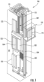
- FIG. 1 is a perspective view of an elevator system 101 including an elevator car 103, a counterweight 105, a tension member 107, a guide rail 109, a machine 111, a position reference system 113, and a controller 115.
- the elevator car 103 and counterweight 105 are connected to each other by the tension member 107.
- the tension member 107 may include or be configured as, for example, ropes, steel cables, and/or coated-steel belts.
- the counterweight 105 is configured to balance a load of the elevator car 103 and is configured to facilitate movement of the elevator car 103 concurrently and in an opposite direction with respect to the counterweight 105 within an elevator shaft or hoistway 117 and along the guide rail 109.
- the tension member 107 engages the machine 111, which is part of an overhead structure of the elevator system 101.
- the machine 111 is configured to control movement between the elevator car 103 and the counterweight 105.
- the position reference system 113 may be mounted on a fixed part at the top of the elevator shaft 117, such as on a support or guide rail, and may be configured to provide position signals related to a position of the elevator car 103 within the elevator shaft 117. In other embodiments, the position reference system 113 may be directly mounted to a moving component of the machine 111, or may be located in other positions and/or configurations as known in the art.
- the position reference system 113 can be any device or mechanism for monitoring a position of an elevator car and/or counter weight, as known in the art.
- the position reference system 113 can be an encoder, sensor, or other system and can include velocity sensing, absolute position sensing, etc., as will be appreciated by those of skill in the art.
- the controller 115 may be located, as shown, in a controller room 121 of the elevator shaft 117 and is configured to control the operation of the elevator system 101, and particularly the elevator car 103. It is to be appreciated that the controller 115 need not be in the controller room 121 but may be in the hoistway or other location in the elevator system. For example, the controller 115 may provide drive signals to the machine 111 to control the acceleration, deceleration, leveling, stopping, etc. of the elevator car 103. The controller 115 may also be configured to receive position signals from the position reference system 113 or any other desired position reference device. When moving up or down within the elevator shaft 117 along guide rail 109, the elevator car 103 may stop at one or more landings 125 as controlled by the controller 115.
- controller 115 can be located and/or configured in other locations or positions within the elevator system 101.
- the controller 115 may be located remotely or in a distributed computing network (e.g., cloud computing architecture).
- the controller 115 may be implemented using a processor-based machine, such as a personal computer, server, distributed computing network, etc.
- the machine 111 may include a motor or similar driving mechanism.
- the machine 111 is configured to include an electrically driven motor.
- the power supply for the motor may be any power source, including a power grid, which, in combination with other components, is supplied to the motor.
- the machine 111 may include a traction sheave that imparts force to tension member 107 to move the elevator car 103 within elevator shaft 117.
- the elevator system 101 also includes one or more elevator doors 104.
- the elevator door 104 may be attached to the elevator car 103 or the elevator door 104 may be located on a landing 125 of the elevator system 101, or both. Embodiments disclosed herein may be applicable to both an elevator door 104 attached to the elevator car 103 or an elevator door 104 located on a landing 125 of the elevator system 101, or both.
- the elevator door 104 opens to allow passengers to enter and exit the elevator car 103.
- the elevator car 103 is located in the elevator shaft 117 and in some embodiments is configurated to rotate in the elevator shaft 117 about a shaft central axis 130.
- the elevator car 103 includes elevator doors 104 interactive with a one of a plurality of landing door sets 132.
- the landing door sets 132 are each located at a landing bay 134 of the landing 125, such that depending on a rotational position of the elevator car 103 and the elevator doors 104 relative to the shaft central axis 130 different landing door sets 1 32 are operated so that different landing bays 134 are utilized to load or unload passengers and/or goods or other objects.
- the landing door sets 132 are generally arranged in an arc in the embodiment of FIG. 2 , but this configuration is merely exemplary and one skilled in the art will readily appreciate that the present disclosure may be readily applied to other landing door sets 132 arrangements.
- widths of adjacent landing bays 134 of the plurality of landing bays 134 overlap at the landing door sets 132.
- first landing bay 134a overlaps with adjacent second landing bay 134b, which also overlaps with adjacent third landing bay 134c.
- third landing bay 134c overlaps with adjacent fourth landing bay 134d.
- landing bays 134 While four landing bays 134 are illustrated and described herein, one skilled in the art will readily appreciate that the present disclosure may be similarly applied to elevator systems 101 with other quantities of landing bays 134 at a particular landing 125, such as two, three, five or more landing bays 134 at a particular landing 125.
- FIG. 2 shows a state of the elevator system 101 where all of the landing door sets 132 are closed.
- the elevator car 103 is positioned about the shaft central axis 130 such that the elevator doors 104 are aligned to operate at the first landing bay 134a.
- Each landing door set 132 includes two landing doors 136.
- first landing door set 132a at the first landing bay 134a includes landing doors 136a and 136b.
- second landing door set 132b located at the second landing bay 134b includes landing doors 136c and 136d
- third landing door set 132c at third landing bay 134c includes landing doors 136e and 136f
- fourth landing door set 132d at fourth landing bay 134d includes landing doors 136g and 136h.
- the elevator doors 104 at the elevator car 103 operably connect to the landing doors 136a and 136b via, for example, a door coupler140 of the elevator doors 104.
- a door mechanism 138 such as a door motor or the like
- the landing doors 136a and 136b are urged toward an open position by the movement of the elevator doors 104 via the door coupler 140.
- the first door landing set 132a spans an entire width of the first landing bay 134a, so that when the landing doors 136a and 136b are in their opened position, such as shown in FIG. 3 , access is gained to the first landing bay 134a from the elevator car 103.
- the elevator car 103 is moved so that the elevator doors 104 align with the second landing door set 132b.
- the landing doors 136c and 136d are operably connected to the elevator doors 104 via the door coupler 140. Operation of the elevator doors 104 via the door mechanism 138 urges the landing doors 136c and 136d toward their opened position. Since, however, the first landing bay 134a overlaps the second landing bay 134b, to allow full access between the second landing bay 134b and the elevator car 103, the first landing door set 132a must be moved at least partially to the opened position.
- the landing door 136d is urged into contact with the landing door 136b of the first landing door set 132a. This contact unlocks the position of the landing door 136b via a first door interlock 142a and second door interlock 142b, and allows the movement of the landing door 136d to drive movement of the landing door 136b so that the second landing door set 132b can achieve the fully opened position as illustrated in FIG. 4 .
- the landing doors 136c and 136d are driven to the closed position, such as illustrated in FIG. 2 , via the door coupler 140 by movement of the elevator doors 104.
- the landing door 136b may return to the closed position by movement of the landing door 136d via the door interlocks 142a and 142b, or alternatively may be urged to the closed position by a first closing element 144a operably connected to the landing door 136b.
- the first closing element 144a may be, for example, a weighted closer or a spring.
- the elevator car 103 is moved so that the elevator doors 104 align with the third landing door set 132c.
- the landing doors 136e and 136f are operably connected to the elevator doors 104 via the door coupler 140. Operation of the elevator doors 104 via the door mechanism 138 urges the landing doors 136e and 136f toward their opened position. Since, however, the second landing bay 134b overlaps the third landing bay 134c, to allow full access between the third landing bay 134c and the elevator car 103, the second landing door set 132b must be moved at least partially to the opened position.
- the landing door 136f is urged into contact with the landing door 136d of the second landing door set 132b. This contact unlocks the position of the landing doors 136c and 136d via a third door interlock 142c, and allows the movement of the landing door 136f to drive movement of the landing doors 136c and 136d so that the third landing door set 132c can achieve the fully opened position as illustrated in FIG. 5 .
- the landing door 136d may urge the landing doors 136a and/or 136b at least partially toward the open position as previously described above.
- the landing doors 136e and 136f are driven to the closed position, such as illustrated in FIG. 2 , via the door coupler 140 by movement of the elevator doors 104.
- the landing doors 136a, 136b, 136c and 136d may return to the closed position by movement of the landing door 136f via the door interlock 142c, or alternatively may be urged to the closed position by closing elements 144a and 144b operably connected to the landing doors 136a, 136b, 136c and 136d.
- the elevator car 103 is moved so that the elevator doors 104 align with the fourth landing door set 132d.
- the landing doors 136g and 136h are operably connected to the elevator doors 104 via the door coupler 140. Operation of the elevator doors 104 via the door mechanism 138 urges the landing doors 136g and 136h toward their opened position. Since, however, the third landing bay 134c overlaps the fourth landing bay 134d, to allow full access between the fourth landing bay 134d and the elevator car 103, the third landing door set 132c must be moved at least partially to the opened position.
- the landing door 136h is urged into contact with the landing door 136f of the third landing door set 132c. This contact unlocks the position of the landing doors 136e and 136f via a door interlock 142d, and allows the movement of the landing door 136h to drive movement of the landing doors 136e and 136f so that the fourth landing door set 132d can achieve the fully opened position as illustrated in FIG. 6 . Additionally, it may be necessary to move the landing doors of the second landing door set 132b and the landing doors of the first landing door set 132a so that the fourth landing door set 132d may reach the fully opened position.
- the landing doors 136g and 136h are driven to the closed position, such as illustrated in FIG. 2 , via the fourth door coupler 138 by movement of the elevator doors 104.
- the landing doors 136a, 136b, 136c, 136d, 136e and 136f may return to the closed position by movement of the landing door 136h via the door interlock 142d, or alternatively may be urged to the closed position by a closing elements 144a, 144b, 144c operably connected to the landing doors 136a, 136b, 136c, 136d, 136e and 136f.
- the landing door configuration and operation described herein reduces the complexity of opening multiple landing doors on the same floor occupying overlapping door space and eliminates the need for landing doors to travel in both directions in relation to close. Further, the cost of the elevator system may be reduced by having a traditional elevator door coupling device mounted to the car doors to open the landing doors, and eliminate the need for powered landing doors. Additionally, the configuration reduces variation of door components in the building.
Landscapes
- Engineering & Computer Science (AREA)
- Civil Engineering (AREA)
- Mechanical Engineering (AREA)
- Structural Engineering (AREA)
- Automation & Control Theory (AREA)
- Elevator Door Apparatuses (AREA)
Abstract
A landing arrangement of an elevator system includes a plurality of landing bays, at least two landing bays of the plurality of landing bays overlapping, and a plurality of landing door sets. Each landing door set of the plurality of landing door sets corresponds to a landing bay of the plurality of landing bays. At least two landing door sets of the plurality of landing door sets are interconnected such that opening a first landing door set of the plurality of landing door sets urges the at least partial opening of a second landing door set adjacent to the first landing door set.
Description
- The embodiments herein relate to elevator systems, and in particular to operation of landing doors of elevator systems.
- In an elevator configuration such as when one car door must open multiple landing doors on a certain floor, there can be constraints such as door opening width, door space and coupling location which complicates the operation of the doors. An example of this situation is one car door opening on a rotating cab accessing 3-4 landing doors per floor. If the multiple landing door openings per floor are close to one another, the required door space for each opening can overlap, making it complicated and expensive to provide a door system the functions and fits in the building layout.
- In one exemplary embodiment, a landing arrangement of an elevator system includes a plurality of landing bays, at least two landing bays of the plurality of landing bays overlapping, and a plurality of landing door sets. Each landing door set of the plurality of landing door sets corresponds to a landing bay of the plurality of landing bays. At least two landing door sets of the plurality of landing door sets are interconnected such that opening a first landing door set of the plurality of landing door sets urges the at least partial opening of a second landing door set adjacent to the first landing door set.
- Particular embodiments further may include at least one, or a plurality of, the following optional features, alone or in combination with each other:
- Additionally or alternatively, in this or other embodiments a closure element is configured to urge the second landing door set to a closed position when the first landing door set is closed.
- Additionally or alternatively, in this or other embodiments the closure element is configured to automatically urge the second landing door set to the closed position.
- Additionally or alternatively, in this or other embodiments each landing door set of the plurality of landing door sets includes two landing doors, and the two landing doors move in a same direction when moved between the closed position and an open position.
- Additionally or alternatively, in this or other embodiments the plurality of landing bays are positioned about an arc relative to a central axis of the elevator system.
- Additionally or alternatively, in this or other embodiments the plurality of landing bays is four landing bays.
- In another exemplary embodiment, an elevator system includes an elevator shaft, an elevator car moveable along the elevator shaft and rotatable about a shaft central axis of the elevator shaft, and a landing arrangement. The landing arrangement includes a plurality of landing bays, at least two landing bays of the plurality of landing bays overlapping, and a plurality of landing door sets. Each landing door set of the plurality of landing door sets corresponds to a landing bay of the plurality of landing bays. At least two landing door sets of the plurality of landing door sets are interconnected such that opening a first landing door set of the plurality of landing door sets urges the at least partial opening of a second landing door set adjacent to the first landing door set.
- Particular embodiments further may include at least one, or a plurality of, the following optional features, alone or in combination with each other:
- Additionally or alternatively, in this or other embodiments the opening of the first landing door set is driven by opening of an elevator car door of the elevator car.
- Additionally or alternatively, in this or other embodiments a closure element is configured to urge the second landing door set to a closed position when the first landing door set is closed.
- Additionally or alternatively, in this or other embodiments the closure element is configured to automatically urge the second landing door set to the closed position.
- Additionally or alternatively, in this or other embodiments each landing door set of the plurality of landing door sets includes two landing doors, and the two landing doors move in a same direction when moved between the closed position and an open position.
- Additionally or alternatively, in this or other embodiments the plurality of landing bays are positioned about an arc relative to the central axis of the elevator shaft.
- Additionally or alternatively, in this or other embodiments the plurality of landing bays is four landing bays.
- In another exemplary embodiment, a method of operating an elevator system includes moving an elevator car along an elevator shaft to a landing floor. The landing floor includes a plurality of landing bays, at least two landing bays of the plurality of landing bays overlapping, and a plurality of landing door sets. each landing door set of the plurality of landing door sets corresponds to a landing bay of the plurality of landing bays. The elevator car is rotated about a central axis of the elevator shaft to a first landing door set of the plurality of landing door sets, and an elevator car door of the elevator car is urged toward the opened position. The first landing door set is urged open via the opening of the elevator car door, and the first landing door set is interconnected to a second landing door set adjacent to the first landing door set. The second landing door set is urged at least partially open via opening of the first landing door set.
- Particular embodiments further may include at least one, or a plurality of, the following optional features, alone or in combination with each other:
- Additionally or alternatively, in this or other embodiments a third landing door set adjacent to the second landing door set is urged at least partially open via opening of the second landing door set.
- Additionally or alternatively, in this or other embodiments the first landing door set is moved to a closed position.
- Additionally or alternatively, in this or other embodiments the second landing door set is moved to a closed position when the first landing door set is closed.
- Additionally or alternatively, in this or other embodiments the second landing door set is automatically urged toward the closed position.
- Additionally or alternatively, in this or other embodiments each landing door set of the plurality of landing door sets includes two landing doors, and the two landing doors move in a same direction when moved between the closed position and an open position.
- Additionally or alternatively, in this or other embodiments the plurality of landing bays are positioned about an arc relative to the central axis of the elevator shaft.
- The foregoing features and elements may be combined in various combinations without exclusivity, unless expressly indicated otherwise. These features and elements as well as the operation thereof will become more apparent in light of the following description and the accompanying drawings. It should be understood, however, that the following description and drawings are intended to be illustrative and explanatory in nature and non-limiting.
- The present disclosure is illustrated by way of example and not limited in the accompanying figures in which like reference numerals indicate similar elements.
-
FIG. 1 is a schematic illustration of an elevator system that may employ various embodiments of the present disclosure; -
FIG. 2 is a schematic illustration of an embodiment of an elevator landing having multiple landing bays; -
FIG. 3 is a schematic illustration of an embodiment of an elevator landing having multiple landing bays where a first bay is opened; -
FIG. 4 is a schematic illustration of an embodiment of an elevator landing having multiple landing bays where a second bay is opened; -
FIG. 5 is a schematic illustration of an embodiment of an elevator landing having multiple landing bays where a third bay is opened; and -
FIG. 6 is a schematic illustration of an embodiment of an elevator landing having multiple landing bays where a fourth bay is opened. -
FIG. 1 is a perspective view of anelevator system 101 including anelevator car 103, acounterweight 105, atension member 107, aguide rail 109, amachine 111, aposition reference system 113, and acontroller 115. Theelevator car 103 andcounterweight 105 are connected to each other by thetension member 107. Thetension member 107 may include or be configured as, for example, ropes, steel cables, and/or coated-steel belts. Thecounterweight 105 is configured to balance a load of theelevator car 103 and is configured to facilitate movement of theelevator car 103 concurrently and in an opposite direction with respect to thecounterweight 105 within an elevator shaft orhoistway 117 and along theguide rail 109. - The
tension member 107 engages themachine 111, which is part of an overhead structure of theelevator system 101. Themachine 111 is configured to control movement between theelevator car 103 and thecounterweight 105. Theposition reference system 113 may be mounted on a fixed part at the top of theelevator shaft 117, such as on a support or guide rail, and may be configured to provide position signals related to a position of theelevator car 103 within theelevator shaft 117. In other embodiments, theposition reference system 113 may be directly mounted to a moving component of themachine 111, or may be located in other positions and/or configurations as known in the art. Theposition reference system 113 can be any device or mechanism for monitoring a position of an elevator car and/or counter weight, as known in the art. For example, without limitation, theposition reference system 113 can be an encoder, sensor, or other system and can include velocity sensing, absolute position sensing, etc., as will be appreciated by those of skill in the art. - The
controller 115 may be located, as shown, in acontroller room 121 of theelevator shaft 117 and is configured to control the operation of theelevator system 101, and particularly theelevator car 103. It is to be appreciated that thecontroller 115 need not be in thecontroller room 121 but may be in the hoistway or other location in the elevator system. For example, thecontroller 115 may provide drive signals to themachine 111 to control the acceleration, deceleration, leveling, stopping, etc. of theelevator car 103. Thecontroller 115 may also be configured to receive position signals from theposition reference system 113 or any other desired position reference device. When moving up or down within theelevator shaft 117 alongguide rail 109, theelevator car 103 may stop at one ormore landings 125 as controlled by thecontroller 115. Although shown in acontroller room 121, those of skill in the art will appreciate that thecontroller 115 can be located and/or configured in other locations or positions within theelevator system 101. In one embodiment, thecontroller 115 may be located remotely or in a distributed computing network (e.g., cloud computing architecture). Thecontroller 115 may be implemented using a processor-based machine, such as a personal computer, server, distributed computing network, etc. - The
machine 111 may include a motor or similar driving mechanism. In accordance with embodiments of the disclosure, themachine 111 is configured to include an electrically driven motor. The power supply for the motor may be any power source, including a power grid, which, in combination with other components, is supplied to the motor. Themachine 111 may include a traction sheave that imparts force totension member 107 to move theelevator car 103 withinelevator shaft 117. - The
elevator system 101 also includes one ormore elevator doors 104. Theelevator door 104 may be attached to theelevator car 103 or theelevator door 104 may be located on alanding 125 of theelevator system 101, or both. Embodiments disclosed herein may be applicable to both anelevator door 104 attached to theelevator car 103 or anelevator door 104 located on alanding 125 of theelevator system 101, or both. Theelevator door 104 opens to allow passengers to enter and exit theelevator car 103. - Referring now to
FIG. 2 , illustrated is an exemplary arrangement of a landing 125 of anelevator system 101. Theelevator car 103 is located in theelevator shaft 117 and in some embodiments is configurated to rotate in theelevator shaft 117 about a shaftcentral axis 130. Theelevator car 103 includeselevator doors 104 interactive with a one of a plurality of landing door sets 132. The landing door sets 132 are each located at a landing bay 134 of thelanding 125, such that depending on a rotational position of theelevator car 103 and theelevator doors 104 relative to the shaftcentral axis 130 different landing door sets 1 32 are operated so that different landing bays 134 are utilized to load or unload passengers and/or goods or other objects. - The landing door sets 132 are generally arranged in an arc in the embodiment of
FIG. 2 , but this configuration is merely exemplary and one skilled in the art will readily appreciate that the present disclosure may be readily applied to other landing door sets 132 arrangements. In the arc arrangement as illustrated, widths of adjacent landing bays 134 of the plurality of landing bays 134 overlap at the landing door sets 132. For example,first landing bay 134a overlaps with adjacentsecond landing bay 134b, which also overlaps with adjacentthird landing bay 134c. Similarly,third landing bay 134c overlaps with adjacentfourth landing bay 134d. While four landing bays 134 are illustrated and described herein, one skilled in the art will readily appreciate that the present disclosure may be similarly applied toelevator systems 101 with other quantities of landing bays 134 at aparticular landing 125, such as two, three, five or more landing bays 134 at aparticular landing 125. - The illustration in
FIG. 2 shows a state of theelevator system 101 where all of the landing door sets 132 are closed. Theelevator car 103 is positioned about the shaftcentral axis 130 such that theelevator doors 104 are aligned to operate at thefirst landing bay 134a. Each landing door set 132 includes two landing doors 136. For example, firstlanding door set 132a at thefirst landing bay 134a includes landingdoors second landing bay 134b includes landingdoors third landing bay 134c includes landingdoors fourth landing bay 134d includes landingdoors - Referring to
FIG. 3 , to open the first landing door set 132a to utilize thefirst landing bay 134a for ingress into theelevator car 103 or egress from theelevator car 103, theelevator doors 104 at theelevator car 103 operably connect to thelanding doors elevator doors 104. When theelevator doors 104 are urged open by adoor mechanism 138, such as a door motor or the like, thelanding doors elevator doors 104 via thedoor coupler 140. The first door landing set 132a spans an entire width of thefirst landing bay 134a, so that when thelanding doors FIG. 3 , access is gained to thefirst landing bay 134a from theelevator car 103. - Referring now to
FIG. 4 , to utilize thesecond landing bay 134b for ingress into theelevator car 103 or egress from theelevator car 103, theelevator car 103 is moved so that theelevator doors 104 align with the second landing door set 132b. The landingdoors elevator doors 104 via thedoor coupler 140. Operation of theelevator doors 104 via thedoor mechanism 138 urges the landingdoors first landing bay 134a overlaps thesecond landing bay 134b, to allow full access between thesecond landing bay 134b and theelevator car 103, the firstlanding door set 132a must be moved at least partially to the opened position. In one embodiment, thelanding door 136d is urged into contact with thelanding door 136b of the firstlanding door set 132a. This contact unlocks the position of thelanding door 136b via afirst door interlock 142a andsecond door interlock 142b, and allows the movement of thelanding door 136d to drive movement of thelanding door 136b so that the second landing door set 132b can achieve the fully opened position as illustrated inFIG. 4 . - To close the second landing door set 132b, the landing
doors FIG. 2 , via thedoor coupler 140 by movement of theelevator doors 104. Thelanding door 136b may return to the closed position by movement of thelanding door 136d via the door interlocks 142a and 142b, or alternatively may be urged to the closed position by afirst closing element 144a operably connected to thelanding door 136b. In some embodiments, thefirst closing element 144a may be, for example, a weighted closer or a spring. - Referring now to
FIG. 5 , to utilize thethird landing bay 134c for ingress into theelevator car 103 or egress from theelevator car 103, theelevator car 103 is moved so that theelevator doors 104 align with the third landing door set 132c. Thelanding doors elevator doors 104 via thedoor coupler 140. Operation of theelevator doors 104 via thedoor mechanism 138 urges thelanding doors second landing bay 134b overlaps thethird landing bay 134c, to allow full access between thethird landing bay 134c and theelevator car 103, the second landing door set 132b must be moved at least partially to the opened position. In one embodiment, thelanding door 136f is urged into contact with thelanding door 136d of the second landing door set 132b. This contact unlocks the position of the landingdoors third door interlock 142c, and allows the movement of thelanding door 136f to drive movement of the landingdoors FIG. 5 . In some embodiments, for the third landing door set 132c to reach the fully opened position, thelanding door 136d may urge thelanding doors 136a and/or 136b at least partially toward the open position as previously described above. - To close the third landing door set 132c, the
landing doors FIG. 2 , via thedoor coupler 140 by movement of theelevator doors 104. Thelanding doors landing door 136f via thedoor interlock 142c, or alternatively may be urged to the closed position by closingelements landing doors - Referring now to
FIG. 6 , to utilize thefourth landing bay 134d for ingress into theelevator car 103 or egress from theelevator car 103, theelevator car 103 is moved so that theelevator doors 104 align with the fourthlanding door set 132d. The landingdoors elevator doors 104 via thedoor coupler 140. Operation of theelevator doors 104 via thedoor mechanism 138 urges the landingdoors third landing bay 134c overlaps thefourth landing bay 134d, to allow full access between thefourth landing bay 134d and theelevator car 103, the third landing door set 132c must be moved at least partially to the opened position. In one embodiment, thelanding door 136h is urged into contact with thelanding door 136f of the third landing door set 132c. This contact unlocks the position of thelanding doors door interlock 142d, and allows the movement of thelanding door 136h to drive movement of thelanding doors landing door set 132d can achieve the fully opened position as illustrated inFIG. 6 . Additionally, it may be necessary to move the landing doors of the second landing door set 132b and the landing doors of the firstlanding door set 132a so that the fourthlanding door set 132d may reach the fully opened position. - To close the fourth
landing door set 132d, the landingdoors FIG. 2 , via thefourth door coupler 138 by movement of theelevator doors 104. Thelanding doors landing door 136h via thedoor interlock 142d, or alternatively may be urged to the closed position by aclosing elements landing doors - The landing door configuration and operation described herein reduces the complexity of opening multiple landing doors on the same floor occupying overlapping door space and eliminates the need for landing doors to travel in both directions in relation to close. Further, the cost of the elevator system may be reduced by having a traditional elevator door coupling device mounted to the car doors to open the landing doors, and eliminate the need for powered landing doors. Additionally, the configuration reduces variation of door components in the building.
- The term "about" is intended to include the degree of error associated with measurement of the particular quantity and/or manufacturing tolerances based upon the equipment available at the time of filing the application.
- The terminology used herein is for the purpose of describing particular embodiments only and is not intended to be limiting of the present disclosure. As used herein, the singular forms "a", "an" and "the" are intended to include the plural forms as well, unless the context clearly indicates otherwise. It will be further understood that the terms "comprises" and/or "comprising," when used in this specification, specify the presence of stated features, integers, steps, operations, elements, and/or components, but do not preclude the presence or addition of one or more other features, integers, steps, operations, element components, and/or groups thereof.
- Those of skill in the art will appreciate that various example embodiments are shown and described herein, each having certain features in the particular embodiments, but the present disclosure is not thus limited. Rather, the present disclosure can be modified to incorporate any number of variations, alterations, substitutions, combinations, sub-combinations, or equivalent arrangements not heretofore described, but which are commensurate with the scope of the present disclosure. Additionally, while various embodiments of the present disclosure have been described, it is to be understood that aspects of the present disclosure may include only some of the described embodiments. Accordingly, the present disclosure is not to be seen as limited by the foregoing description, but is only limited by the scope of the appended claims.
Claims (15)
- A landing arrangement of an elevator system, comprising:a plurality of landing bays, at least two landing bays of the plurality of landing bays overlapping; anda plurality of landing door sets, each landing door set of the plurality of landing door sets corresponding to a landing bay of the plurality of landing bays;wherein at least two landing door sets of the plurality of landing door sets are interconnected such that opening a first landing door set of the plurality of landing door sets urges the at least partial opening of a second landing door set adjacent to the first landing door set.
- The landing arrangement of claim 1, further comprising a closure element configured to urge the second landing door set to a closed position when the first landing door set is closed.
- The landing arrangement of claim 2, wherein the closure element is configured to automatically urge the second landing door set to the closed position.
- The landing arrangement of any of claims 1 to 3, wherein:each landing door set of the plurality of landing door sets includes two landing doors; andthe two landing doors move in a same direction when moved between the closed position and an open position.
- The landing arrangement of any of claims 1 to 4, wherein the plurality of landing bays are positioned about an arc relative to a central axis of the elevator system.
- The landing arrangement of any of claims 1 to 5, wherein the plurality of landing bays is four landing bays.
- An elevator system, comprising:an elevator shaft;an elevator car moveable along the elevator shaft and rotatable about a shaft central axis of the elevator shaft; anda landing arrangement according to any of claims 1 to 6. The elevator system of claim 7, wherein the opening of the first landing door set is driven by opening of an elevator car door of the elevator car.
- The elevator system of claim 7, further comprising a closure element configured to urge the second landing door set to a closed position when the first landing door set is closed.
- A method of operating an elevator system, comprising:moving an elevator car along an elevator shaft to a landing floor, the landing floor including:a plurality of landing bays, at least two landing bays of the plurality of landing bays overlapping; anda plurality of landing door sets, each landing door set of the plurality of landing door sets corresponding to a landing bay of the plurality of landing bays;rotating the elevator car about a central axis of the elevator shaft to a first landing door set of the plurality of landing door sets;opening an elevator car door of the elevator car;urging opening of the first landing door set via the opening of the elevator car door;interconnecting the first landing door set to a second landing door set adjacent to the first landing door set; andurging at least partial opening of the second landing door set via opening of the first landing door set.
- The method of claim 9, further comprising urging at least partial opening of a third landing door set adjacent to the second landing door set via opening of the second landing door set.
- The method of claim 9 or 10, further comprising moving the first landing door set to a closed position.
- The method of claim 11, further comprising moving the second landing door set to a closed position when the first landing door set is closed.
- The method of claim 12, wherein the second landing door set is automatically urged toward the closed position.
- The method of any of claims 9 to 13, wherein:each landing door set of the plurality of landing door sets includes two landing doors; andthe two landing doors move in a same direction when moved between the closed position and an open position.
- The method of any of claims 9 to 14, wherein the plurality of landing bays are positioned about an arc relative to the central axis of the elevator shaft.
Applications Claiming Priority (1)
| Application Number | Priority Date | Filing Date | Title |
|---|---|---|---|
| US18/537,026 US12378095B2 (en) | 2023-12-12 | 2023-12-12 | System and method of unlocking and opening multiple panel elevator doors |
Publications (1)
| Publication Number | Publication Date |
|---|---|
| EP4570729A1 true EP4570729A1 (en) | 2025-06-18 |
Family
ID=93840973
Family Applications (1)
| Application Number | Title | Priority Date | Filing Date |
|---|---|---|---|
| EP24217831.7A Pending EP4570729A1 (en) | 2023-12-12 | 2024-12-05 | System and method of unlocking and opening multiple panel elevator doors |
Country Status (3)
| Country | Link |
|---|---|
| US (1) | US12378095B2 (en) |
| EP (1) | EP4570729A1 (en) |
| CN (1) | CN120135910A (en) |
Citations (4)
| Publication number | Priority date | Publication date | Assignee | Title |
|---|---|---|---|---|
| JPH08175773A (en) * | 1994-12-27 | 1996-07-09 | Hazama Gumi Ltd | lift device |
| KR101380238B1 (en) * | 2013-04-05 | 2014-04-04 | 홍익대학교 산학협력단 | Multiple segment transfer unit |
| JP2017019574A (en) * | 2015-07-07 | 2017-01-26 | 三菱電機ビルテクノサービス株式会社 | 4-way open cylindrical elevator |
| JP2020152577A (en) * | 2020-06-23 | 2020-09-24 | フジテック株式会社 | Elevator system |
Family Cites Families (5)
| Publication number | Priority date | Publication date | Assignee | Title |
|---|---|---|---|---|
| US4785579A (en) * | 1987-03-19 | 1988-11-22 | Nippon Air Brake Co., Ltd. | Circular door operating method and apparatus |
| JPH10139318A (en) * | 1996-11-11 | 1998-05-26 | Sekisui Chem Co Ltd | Rotary elevator |
| EP2177467A1 (en) * | 2008-10-14 | 2010-04-21 | BC Lift A/S | Rotating Elevator |
| KR101431719B1 (en) * | 2013-04-05 | 2014-08-20 | 홍익대학교 산학협력단 | Transfer unit and system using hard rail core |
| KR101928993B1 (en) * | 2018-07-26 | 2018-12-13 | 정장효 | Cylindrical Elevator Having Safety Device, and Operating Method Thereof |
-
2023
- 2023-12-12 US US18/537,026 patent/US12378095B2/en active Active
-
2024
- 2024-12-05 EP EP24217831.7A patent/EP4570729A1/en active Pending
- 2024-12-10 CN CN202411809207.3A patent/CN120135910A/en active Pending
Patent Citations (4)
| Publication number | Priority date | Publication date | Assignee | Title |
|---|---|---|---|---|
| JPH08175773A (en) * | 1994-12-27 | 1996-07-09 | Hazama Gumi Ltd | lift device |
| KR101380238B1 (en) * | 2013-04-05 | 2014-04-04 | 홍익대학교 산학협력단 | Multiple segment transfer unit |
| JP2017019574A (en) * | 2015-07-07 | 2017-01-26 | 三菱電機ビルテクノサービス株式会社 | 4-way open cylindrical elevator |
| JP2020152577A (en) * | 2020-06-23 | 2020-09-24 | フジテック株式会社 | Elevator system |
Also Published As
| Publication number | Publication date |
|---|---|
| CN120135910A (en) | 2025-06-13 |
| US12378095B2 (en) | 2025-08-05 |
| US20250187877A1 (en) | 2025-06-12 |
Similar Documents
| Publication | Publication Date | Title |
|---|---|---|
| CN107954297B (en) | Elevator car, elevator system and method for inspecting, maintaining and/or repairing an elevator system | |
| CN110304528B (en) | Elevator car ceiling access system | |
| JP5940220B2 (en) | Elevator car door lock device | |
| US20180086604A1 (en) | Elevator car wall for access to hoistway | |
| EP4353647B1 (en) | Car door interlock | |
| EP3693318B1 (en) | Elevator car door interlock | |
| US12378095B2 (en) | System and method of unlocking and opening multiple panel elevator doors | |
| CN110436313B (en) | Openable elevator car wall plate | |
| EP3459895A1 (en) | Elevator safety gear assembly | |
| US3447637A (en) | Elevator system | |
| PT1775250E (en) | Door device of elevator | |
| US12139374B2 (en) | Method and device for monitoring an elevator system | |
| US20190210836A1 (en) | Elevator maintenance access systems | |
| JP7756814B2 (en) | elevator equipment | |
| EP4691956A1 (en) | Elevator system and methods of installing and deinstalling a mobile working platform in such elevator system | |
| EP4477607B1 (en) | Brake circuit access from landing | |
| US20260138851A1 (en) | Lost motion slider for operating an elevator car door interlock | |
| US20250011130A1 (en) | Elevator systems | |
| EP3566995B1 (en) | Elevator car door coupling systems | |
| CN119429902A (en) | Elevator car, elevator system, and method for providing access to an area outside an elevator car | |
| CN121448913A (en) | Elevator car, elevator system and method for reaching space in elevator system shaft | |
| CN120080877A (en) | A hoisting fully enclosed platform door structure | |
| JPH01156295A (en) | Elevator door opening/closing control device |
Legal Events
| Date | Code | Title | Description |
|---|---|---|---|
| PUAI | Public reference made under article 153(3) epc to a published international application that has entered the european phase |
Free format text: ORIGINAL CODE: 0009012 |
|
| STAA | Information on the status of an ep patent application or granted ep patent |
Free format text: STATUS: THE APPLICATION HAS BEEN PUBLISHED |
|
| AK | Designated contracting states |
Kind code of ref document: A1 Designated state(s): AL AT BE BG CH CY CZ DE DK EE ES FI FR GB GR HR HU IE IS IT LI LT LU LV MC ME MK MT NL NO PL PT RO RS SE SI SK SM TR |
|
| STAA | Information on the status of an ep patent application or granted ep patent |
Free format text: STATUS: REQUEST FOR EXAMINATION WAS MADE |
|
| 17P | Request for examination filed |
Effective date: 20251114 |