EP4570711A2 - Conveyance apparatus - Google Patents
Conveyance apparatus Download PDFInfo
- Publication number
- EP4570711A2 EP4570711A2 EP24203617.6A EP24203617A EP4570711A2 EP 4570711 A2 EP4570711 A2 EP 4570711A2 EP 24203617 A EP24203617 A EP 24203617A EP 4570711 A2 EP4570711 A2 EP 4570711A2
- Authority
- EP
- European Patent Office
- Prior art keywords
- conveyance
- article
- front surface
- chute
- conveyance apparatus
- Prior art date
- Legal status (The legal status is an assumption and is not a legal conclusion. Google has not performed a legal analysis and makes no representation as to the accuracy of the status listed.)
- Pending
Links
Images


Classifications
-
- B—PERFORMING OPERATIONS; TRANSPORTING
- B65—CONVEYING; PACKING; STORING; HANDLING THIN OR FILAMENTARY MATERIAL
- B65G—TRANSPORT OR STORAGE DEVICES, e.g. CONVEYORS FOR LOADING OR TIPPING, SHOP CONVEYOR SYSTEMS OR PNEUMATIC TUBE CONVEYORS
- B65G11/00—Chutes
- B65G11/16—Interior surfaces; Linings
- B65G11/163—Interior surfaces; Linings for articles
-
- B—PERFORMING OPERATIONS; TRANSPORTING
- B65—CONVEYING; PACKING; STORING; HANDLING THIN OR FILAMENTARY MATERIAL
- B65G—TRANSPORT OR STORAGE DEVICES, e.g. CONVEYORS FOR LOADING OR TIPPING, SHOP CONVEYOR SYSTEMS OR PNEUMATIC TUBE CONVEYORS
- B65G29/00—Rotary conveyors, e.g. rotating discs, arms, star-wheels or cones
-
- B—PERFORMING OPERATIONS; TRANSPORTING
- B65—CONVEYING; PACKING; STORING; HANDLING THIN OR FILAMENTARY MATERIAL
- B65G—TRANSPORT OR STORAGE DEVICES, e.g. CONVEYORS FOR LOADING OR TIPPING, SHOP CONVEYOR SYSTEMS OR PNEUMATIC TUBE CONVEYORS
- B65G45/00—Lubricating, cleaning, or clearing devices
- B65G45/02—Lubricating devices
-
- B—PERFORMING OPERATIONS; TRANSPORTING
- B65—CONVEYING; PACKING; STORING; HANDLING THIN OR FILAMENTARY MATERIAL
- B65G—TRANSPORT OR STORAGE DEVICES, e.g. CONVEYORS FOR LOADING OR TIPPING, SHOP CONVEYOR SYSTEMS OR PNEUMATIC TUBE CONVEYORS
- B65G47/00—Article or material-handling devices associated with conveyors; Methods employing such devices
- B65G47/52—Devices for transferring articles or materials between conveyors i.e. discharging or feeding devices
- B65G47/64—Switching conveyors
-
- G—PHYSICS
- G01—MEASURING; TESTING
- G01G—WEIGHING
- G01G19/00—Weighing apparatus or methods adapted for special purposes not provided for in the preceding groups
- G01G19/387—Weighing apparatus or methods adapted for special purposes not provided for in the preceding groups for combinatorial weighing, i.e. selecting a combination of articles whose total weight or number is closest to a desired value
- G01G19/393—Weighing apparatus or methods adapted for special purposes not provided for in the preceding groups for combinatorial weighing, i.e. selecting a combination of articles whose total weight or number is closest to a desired value using two or more weighing units
-
- B—PERFORMING OPERATIONS; TRANSPORTING
- B65—CONVEYING; PACKING; STORING; HANDLING THIN OR FILAMENTARY MATERIAL
- B65G—TRANSPORT OR STORAGE DEVICES, e.g. CONVEYORS FOR LOADING OR TIPPING, SHOP CONVEYOR SYSTEMS OR PNEUMATIC TUBE CONVEYORS
- B65G2201/00—Indexing codes relating to handling devices, e.g. conveyors, characterised by the type of product or load being conveyed or handled
- B65G2201/02—Articles
- B65G2201/0202—Agricultural and processed food products
-
- B—PERFORMING OPERATIONS; TRANSPORTING
- B65—CONVEYING; PACKING; STORING; HANDLING THIN OR FILAMENTARY MATERIAL
- B65G—TRANSPORT OR STORAGE DEVICES, e.g. CONVEYORS FOR LOADING OR TIPPING, SHOP CONVEYOR SYSTEMS OR PNEUMATIC TUBE CONVEYORS
- B65G2207/00—Indexing codes relating to constructional details, configuration and additional features of a handling device, e.g. Conveyors
- B65G2207/26—Hygienic features, e.g. easy to sanitize
Definitions
- the present invention relates to a conveyance apparatus.
- a known combination weighing apparatus includes a trough and a chute, both of which utilize shutter processing as a technique of antisticking.
- such a combination weighing apparatus has a problem that when an article containing a large amount of fat such as chicken thigh or beef (slice) is conveyed, the fat adheres to a conveyance surface of a conveyance unit that conveys an article, such as a trough or a chute, and conveyance performance is deteriorated as a production time elapses.
- a conveyance unit that conveys an article, such as a trough or a chute
- the present invention has been made in view of the above problem, and an object of the present invention is to provide a conveyance apparatus that can reduce deterioration in conveyance performance even when an article containing fat on the surface thereof is conveyed.
- a conveyance apparatus includes: a conveyance unit configured to convey an article that is charged from an outside and contains fat on at least a surface of the article, wherein a hydrophilic coating layer is formed on a conveyance front surface of the conveyance unit.
- a conveyance apparatus 1 according to a first embodiment of the present invention will be described with reference to FIGS. 1 to 8 .
- a combination weighing apparatus will be described as an example of the conveyance apparatus 1, but the present invention is not limited thereto.
- the combination weighing apparatus is an apparatus that calculates an article supplied from a conveyor disposed upstream so that an article has a target weight value, and supplies the calculated article to a downstream apparatus.
- the conveyance apparatus 1 includes a dispersion table 10, a plurality of troughs (conveyance feeders) 11, a pool hopper 12, a weighing hopper 13, and a chute 9.
- the conveyance apparatus 1 may be a timing hopper that temporarily receives the article discharged from the chute 9 and then discharges the article downstream.
- the dispersion table 10 receives an article charged from the outside and discharges the article in the circumferential direction.
- the dispersion table 10 may include a vibrator, and may convey the article in the circumferential direction on the basis of the vibration component applied by the vibrator.
- the configuration in which the dispersion table 10 conveys the article by vibration has been described.
- the dispersion table 10 may include a substantially conical member, and may rotate around an apex as a rotation center.
- Each of the plurality of troughs 11 receives the article discharged from the dispersion table 10 and conveys the article further downstream.
- the trough 11 may include a vibrator, and may convey the article further downstream on the basis of the vibration component applied by the vibrator.
- the pool hopper 12 opens and closes the gate to temporarily retain the article discharged from the trough 11 and then to discharge the article to the weighing hopper 13 disposed downstream.
- the weighing hopper 13 opens and closes the gate to temporarily retain the article discharged from the pool hopper 12 and to acquire a weight value of the retained article. Thereafter, when the retained article is selected as a result of combination calculation by a control unit (not illustrated), the weighing hopper 13 discharges the retained article to the downstream chute 9.
- the chute 9 collects the articles discharged from the weighing hopper 13 at one place and discharges the articles downward.
- the configuration in which the article is discharged from the weighing hopper 13 has been described.
- the present invention is not limited to this configuration.
- an article discharged from the booster hopper may be received.
- a hydrophilic coating layer 2 is formed on a conveyance front surface 31 of a conveyance unit 3 of the conveyance apparatus 1.
- the conveyance unit 3 includes the dispersion table 10, the plurality of troughs 11, the pool hopper 12, the weighing hopper 13, the booster hopper, and the chute 9. That is, the hydrophilic coating layer 2 is formed on the conveyance front surface of the plurality of troughs 11 and the conveyance front surface of the chute 9.
- the hydrophilic coating layer 2 is formed on the surfaces of the pool hopper 12 and the weighing hopper 13, which are to come into contact with the article.
- the surfaces that are to come into contact with the article includes surfaces that are to come into contact with the article in a cylindrical member and a gate.
- the cylindrical member and the gate constitute the hopper.
- the cylindrical member has an open top and bottom. The gate closes an opening located below the cylindrical member.
- the type of the hydrophilic coating layer 2 is roughly classified into an inorganic type and an organic type.
- the inorganic coating layer is formed by using a photocatalyst represented by titanium oxide. Specifically, the inorganic coating layer is formed by forming a highly hydrophilic hydroxyl group on the surface of titanium oxide by sunlight (mainly ultraviolet rays).
- the organic coating layer is formed by using a resin containing an ion or a hydrophobic group.
- a contact angle A1 between the conveyance front surface 31 on which the hydrophilic coating layer 2 is formed and a water droplet W formed on the conveyance front surface 31 is 40 degrees or less.
- the result of an experiment reveals that, according to such a configuration, the affinity between the above-described conveyance front surface 31 and water molecules is increased and hydrophilicity is developed.
- the result similarly reveals that hydrophobicity is developed when the contact angle A1 is from 40 degrees to 90 degrees, and water repellency is exhibited when the contact angle A1 is 90 degrees or more.
- a plurality of protrusions may be provided on the conveyance front surface 31 described above.
- a plurality of protrusions 92 may be provided on a conveyance front surface 91 of the trough 11.
- a plurality of protrusions 22 may be provided on a conveyance front surface 23 of the chute 9.
- the plurality of protrusions 22/92 may be formed by embossing.
- the plurality of protrusions 22/92 may be formed by shutter processing.
- the shutter processing may be louver processing.
- the conveyance front surface 23/91 subjected to the shutter processing has a structure in which when the conveyance front surface 23/91 is viewed from the front, a space on the other side of the chute 9/trough 11 is not visible, and can be visible by shifting the viewpoint.
- an opening 21A/91A directed from the conveyance front surface 23/91 to a back surface 24/93 is formed at a downstream end 22E/92E of each of the plurality of protrusions 22/92.
- the back surface 24 is the back surface of the chute 9
- the back surface 93 is the back surface of the trough 11.
- the opening 21A is formed from the conveyance front surface 23 of the chute 9 toward the back surface 24, and the opening 91A is formed from the conveyance front surface 91 of the trough 11 toward the back surface 93.
- the trough 11 includes a first sliding surface 91 and a second sliding surface 92.
- the first sliding surface 91 includes a plurality of the openings 91A.
- the second sliding surface 92 closes a part of the openings 91A and is disposed at a position on an inner side I of the trough 11 with respect to the first sliding surface 91.
- the second sliding surface 92 is formed continuously with the first sliding surface 91 on an upstream side U, a left side L, and a right side R of the above-described opening 91A.
- the second sliding surface 92 includes a left-side plane 92L, a right-side plane 92R, and an upper-side plane 92U.
- the left-side plane 92L is formed so as to rise from the first sliding surface 91 toward the inner side I on the left side L of the opening 91A.
- the right-side plane 92R is formed so as to rise from the first sliding surface 91 toward the inner side I on the right side R of the opening 91A.
- the upper-side plane 92U is formed so as to connect the left-side plane 92L and the right-side plane 92R.
- the chute 9 includes a first sliding surface 23 and a second sliding surface 22.
- the first sliding surface 23 includes a plurality of the openings 21A.
- the second sliding surface 22 closes a part of the openings 21A and is disposed at a position on the inner side I of the chute 9 with respect to the first sliding surface 23.
- the second sliding surface 22 is formed continuously with the first sliding surface 23 on the upstream side U, the left side L, and the right side R of the above-described opening 21A.
- the second sliding surface 22 includes a left-side plane 22L, a right-side plane 22R, and an upper-side plane 22U.
- the left-side plane 22L is formed so as to rise from the first sliding surface 23 toward the inner side I on the left side L of the above-described opening 21A.
- the right-side plane 22R is formed so as to rise from the first sliding surface 23 toward the inner side I on the right side R of the opening 21A.
- the upper-side plane 22U is formed so as to connect the left-side plane 22L and the right-side plane 22R.
- the plurality of protrusions 22/92 can further reduce deterioration of the performance of conveying an article containing fat on the surface.
- an angle A2 formed by the trough 11 and a horizontal direction H may be in a range of 9 to 12 degrees.
- an angle A3 formed by the chute 9 and the horizontal direction H may be in a range of 40 to 60 degrees.
- a decrease in the performance of conveying an article containing fat on the surface can be reduced.
- a hydrophilic coating layer when used, a thin water film can be formed on the conveyance surface.
- direct contact between at least fat on the surface of the article and the conveyance surface can be reduced, and adhesion between the articles can be reduced.
- the effect of the hydrophilic coating layer such as water repellency can be maintained for a long period of time as compared with other coating layers.
Landscapes
- Engineering & Computer Science (AREA)
- Mechanical Engineering (AREA)
- Physics & Mathematics (AREA)
- General Physics & Mathematics (AREA)
- Chutes (AREA)
- Jigging Conveyors (AREA)
- Container, Conveyance, Adherence, Positioning, Of Wafer (AREA)
Abstract
Description
- The present invention relates to a conveyance apparatus.
- In the related art, a known combination weighing apparatus includes a trough and a chute, both of which utilize shutter processing as a technique of antisticking.
-
- Patent Literature 1:
WO 2014/067533 A1 - Patent Literature 2:
JP 2020-2336 A1 - However, such a combination weighing apparatus has a problem that when an article containing a large amount of fat such as chicken thigh or beef (slice) is conveyed, the fat adheres to a conveyance surface of a conveyance unit that conveys an article, such as a trough or a chute, and conveyance performance is deteriorated as a production time elapses.
- The present invention has been made in view of the above problem, and an object of the present invention is to provide a conveyance apparatus that can reduce deterioration in conveyance performance even when an article containing fat on the surface thereof is conveyed.
- A conveyance apparatus according to an embodiment includes: a conveyance unit configured to convey an article that is charged from an outside and contains fat on at least a surface of the article, wherein a hydrophilic coating layer is formed on a conveyance front surface of the conveyance unit.
- According to the present invention, it is possible to provide a conveyance apparatus that can reduce deterioration in conveyance performance even when an article containing fat on the surface thereof is conveyed.
-
-
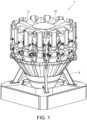
FIG. 1 is a diagram for describing an example of an overall configuration of a conveyance apparatus according to a first embodiment; -
FIG. 2 is a diagram for describing an example of a coating layer formed on a conveyance front surface of a conveyance unit of the conveyance apparatus according to the first embodiment; -
FIG. 3 is a diagram illustrating a part of a conveyance front surface of a trough of the conveyance apparatus according to the first embodiment; -
FIG. 4 is a diagram illustrating a part of a conveyance front surface of a chute of the conveyance apparatus according to the first embodiment; -
FIG. 5 is a diagram illustrating a part of the conveyance front surface of the chute/trough of the conveyance apparatus according to the first embodiment; -
FIG. 6 is a sectional view taken along line X-X inFIG. 5 ; -
FIG. 7 is an example of a side view of the trough of the conveyance apparatus according to the first embodiment; and -
FIG. 8 is an example of a side view of the chute of the conveyance apparatus according to the first embodiment. - Hereinafter, the present embodiment will be described in detail with reference to the attached drawings. In the following description of the drawings, the same or similar parts are denoted by the same or similar reference symbols. However, note that the drawings are schematic, and ratios of dimensions are different from actual ones. Therefore, specific dimensions and the like are determined in consideration of the following description. Moreover, there may be portions where dimensional relationships or proportions are different among the drawings. In this specification and the drawings, elements having substantially the same function and configuration are denoted by the same reference numerals to omit redundant description, and elements not directly related to the present invention are omitted.
- Hereinafter, a
conveyance apparatus 1 according to a first embodiment of the present invention will be described with reference toFIGS. 1 to 8 . In the present embodiment, a combination weighing apparatus will be described as an example of theconveyance apparatus 1, but the present invention is not limited thereto. Note that the combination weighing apparatus is an apparatus that calculates an article supplied from a conveyor disposed upstream so that an article has a target weight value, and supplies the calculated article to a downstream apparatus. - As illustrated in
FIG. 1 , theconveyance apparatus 1 according to the present embodiment includes a dispersion table 10, a plurality of troughs (conveyance feeders) 11, a pool hopper 12, a weighing hopper 13, and achute 9. Note that theconveyance apparatus 1 may be a timing hopper that temporarily receives the article discharged from thechute 9 and then discharges the article downstream. - The dispersion table 10 receives an article charged from the outside and discharges the article in the circumferential direction. Specifically, the dispersion table 10 may include a vibrator, and may convey the article in the circumferential direction on the basis of the vibration component applied by the vibrator. In the above-described example, the configuration in which the dispersion table 10 conveys the article by vibration has been described. However, for example, the dispersion table 10 may include a substantially conical member, and may rotate around an apex as a rotation center.
- Each of the plurality of
troughs 11 receives the article discharged from the dispersion table 10 and conveys the article further downstream. Specifically, thetrough 11 may include a vibrator, and may convey the article further downstream on the basis of the vibration component applied by the vibrator. - The pool hopper 12 opens and closes the gate to temporarily retain the article discharged from the
trough 11 and then to discharge the article to the weighing hopper 13 disposed downstream. - The weighing hopper 13 opens and closes the gate to temporarily retain the article discharged from the pool hopper 12 and to acquire a weight value of the retained article. Thereafter, when the retained article is selected as a result of combination calculation by a control unit (not illustrated), the weighing hopper 13 discharges the retained article to the
downstream chute 9. - The
chute 9 collects the articles discharged from the weighing hopper 13 at one place and discharges the articles downward. In the present embodiment, the configuration in which the article is discharged from the weighing hopper 13 has been described. However, the present invention is not limited to this configuration. When a booster hopper is disposed, an article discharged from the booster hopper may be received. - As illustrated in
FIG. 2 , ahydrophilic coating layer 2 is formed on aconveyance front surface 31 of aconveyance unit 3 of theconveyance apparatus 1. Here, in the present embodiment, theconveyance unit 3 includes the dispersion table 10, the plurality oftroughs 11, the pool hopper 12, the weighing hopper 13, the booster hopper, and thechute 9. That is, thehydrophilic coating layer 2 is formed on the conveyance front surface of the plurality oftroughs 11 and the conveyance front surface of thechute 9. - Further, the
hydrophilic coating layer 2 is formed on the surfaces of the pool hopper 12 and the weighing hopper 13, which are to come into contact with the article. Here, the surfaces that are to come into contact with the article includes surfaces that are to come into contact with the article in a cylindrical member and a gate. The cylindrical member and the gate constitute the hopper. The cylindrical member has an open top and bottom. The gate closes an opening located below the cylindrical member. - The type of the
hydrophilic coating layer 2 is roughly classified into an inorganic type and an organic type. The inorganic coating layer is formed by using a photocatalyst represented by titanium oxide. Specifically, the inorganic coating layer is formed by forming a highly hydrophilic hydroxyl group on the surface of titanium oxide by sunlight (mainly ultraviolet rays). The organic coating layer is formed by using a resin containing an ion or a hydrophobic group. - For example, as illustrated in
FIG. 2 , a contact angle A1 between theconveyance front surface 31 on which thehydrophilic coating layer 2 is formed and a water droplet W formed on theconveyance front surface 31 is 40 degrees or less. The result of an experiment reveals that, according to such a configuration, the affinity between the above-describedconveyance front surface 31 and water molecules is increased and hydrophilicity is developed. The result similarly reveals that hydrophobicity is developed when the contact angle A1 is from 40 degrees to 90 degrees, and water repellency is exhibited when the contact angle A1 is 90 degrees or more. - A plurality of protrusions may be provided on the
conveyance front surface 31 described above. For example, as illustrated inFIG. 3 , a plurality ofprotrusions 92 may be provided on a conveyancefront surface 91 of thetrough 11. As illustrated inFIG. 4 , a plurality ofprotrusions 22 may be provided on aconveyance front surface 23 of thechute 9. - Here, the plurality of
protrusions 22/92 may be formed by embossing. - Alternatively, the plurality of
protrusions 22/92 may be formed by shutter processing. The shutter processing may be louver processing. Theconveyance front surface 23/91 subjected to the shutter processing has a structure in which when theconveyance front surface 23/91 is viewed from the front, a space on the other side of thechute 9/trough 11 is not visible, and can be visible by shifting the viewpoint. - As illustrated in
FIGS. 5 and6 , anopening 21A/91A directed from theconveyance front surface 23/91 to a back surface 24/93 is formed at adownstream end 22E/92E of each of the plurality ofprotrusions 22/92. Here, the back surface 24 is the back surface of thechute 9, and the back surface 93 is the back surface of thetrough 11. Theopening 21A is formed from theconveyance front surface 23 of thechute 9 toward the back surface 24, and theopening 91A is formed from theconveyance front surface 91 of thetrough 11 toward the back surface 93. - In other words, as illustrated in
FIGS. 5 and6 , thetrough 11 includes a first slidingsurface 91 and a second slidingsurface 92. The first slidingsurface 91 includes a plurality of theopenings 91A. The second slidingsurface 92 closes a part of theopenings 91A and is disposed at a position on an inner side I of thetrough 11 with respect to the first slidingsurface 91. - The second sliding
surface 92 is formed continuously with the first slidingsurface 91 on an upstream side U, a left side L, and a right side R of the above-describedopening 91A. - Specifically, as illustrated in
FIG. 5 , the second slidingsurface 92 includes a left-side plane 92L, a right-side plane 92R, and an upper-side plane 92U. - Here, as illustrated in
FIG. 5 , the left-side plane 92L is formed so as to rise from the first slidingsurface 91 toward the inner side I on the left side L of theopening 91A. - As illustrated in
FIG. 5 , the right-side plane 92R is formed so as to rise from the first slidingsurface 91 toward the inner side I on the right side R of theopening 91A. - Further, as illustrated in
FIG. 5 , the upper-side plane 92U is formed so as to connect the left-side plane 92L and the right-side plane 92R. - Similarly, as illustrated in
FIGS. 5 and6 , thechute 9 includes a first slidingsurface 23 and a second slidingsurface 22. The first slidingsurface 23 includes a plurality of theopenings 21A. The second slidingsurface 22 closes a part of theopenings 21A and is disposed at a position on the inner side I of thechute 9 with respect to the first slidingsurface 23. - The second sliding
surface 22 is formed continuously with the first slidingsurface 23 on the upstream side U, the left side L, and the right side R of the above-describedopening 21A. - Specifically, as illustrated in
FIG. 5 , the second slidingsurface 22 includes a left-side plane 22L, a right-side plane 22R, and an upper-side plane 22U. - Here, as illustrated in
FIG. 5 , the left-side plane 22L is formed so as to rise from the first slidingsurface 23 toward the inner side I on the left side L of the above-describedopening 21A. - As illustrated in
FIG. 5 , the right-side plane 22R is formed so as to rise from the first slidingsurface 23 toward the inner side I on the right side R of theopening 21A. - Further, as illustrated in
FIG. 5 , the upper-side plane 22U is formed so as to connect the left-side plane 22L and the right-side plane 22R. - According to the above-described configuration, the plurality of
protrusions 22/92 can further reduce deterioration of the performance of conveying an article containing fat on the surface. - As illustrated in
FIG. 7 , when thetrough 11 is viewed from the side, an angle A2 formed by thetrough 11 and a horizontal direction H may be in a range of 9 to 12 degrees. As illustrated inFIG. 8 , when thechute 9 is viewed from the side, an angle A3 formed by thechute 9 and the horizontal direction H may be in a range of 40 to 60 degrees. According to such configurations, the overall height of the combination weighing apparatus can be reduced while maintaining the conveyance performance as compared with the case in which the hydrophilic coating layer is not formed. This makes it easy to support heights of plants different for each customer. - According to the
conveyance apparatus 1 according to the present embodiment, a decrease in the performance of conveying an article containing fat on the surface can be reduced. Compared to known coating layers having water repellency characteristics, when a hydrophilic coating layer is used, a thin water film can be formed on the conveyance surface. By the action of the water film formed in this manner, direct contact between at least fat on the surface of the article and the conveyance surface can be reduced, and adhesion between the articles can be reduced. Furthermore, since the water film is formed between the article and the conveyance surface to reduce direct contact between the article and the conveyance surface, the effect of the hydrophilic coating layer such as water repellency can be maintained for a long period of time as compared with other coating layers. - Although the present invention is explained in detail using the above-mentioned embodiments, it will be apparent to those skilled in the art that the present invention is not limited to the embodiments described herein. The present invention can be implemented as modifications and changes without departing from the spirit and scope of the present invention defined by the description of the claims. Accordingly, the description of the present specification is for the purpose of illustration and is not intended to limit the present invention in any way.
-
- 1 Conveyance apparatus
- 2 Coating layer
- 3 Conveyance unit
- 23, 31, 91 Conveyance front surface (First sliding surface)
- 9 Chute
- 10 Dispersion table
- 11 Trough
- 21A, 91A Opening
- 22L, 92L Left-side plane
- 22R, 92R Right-side plane
- 22U, 92U Upper-side plane
- 22, 92 Protrusion (Second sliding surface)
- 22E, 92E Downstream end
- W Water droplet
Claims (8)
- A conveyance apparatus comprising:a conveyance unit configured to convey an article that is charged from an outside and contains fat on at least a surface of the article, whereina hydrophilic coating layer is formed on a conveyance front surface of the conveyance unit.
- The conveyance apparatus according to claim 1, wherein
the conveyance front surface includes a plurality of protrusions. - The conveyance apparatus according to claim 2, wherein
an opening directed from the conveyance front surface to a back surface is formed at a downstream end of each of the plurality of protrusions. - The conveyance apparatus according to claim 2 or 3, wherein
the plurality of protrusions is formed by shutter processing. - The conveyance apparatus according to claim 2 or 3, wherein
the plurality of protrusions is formed by embossing. - The conveyance apparatus according to any of the preceding claims, whereinthe conveyance unit includes a trough, andwhen the trough is viewed from a side, an angle formed by the trough and a horizontal direction is in a range of 9 to 12 degrees.
- The conveyance apparatus according to any of the preceding claims, whereinthe conveyance unit includes a chute, andwhen the chute is viewed from a side, an angle formed by the chute and a horizontal direction is in a range of 40 to 60 degrees.
- The conveyance apparatus according to any of the preceding claims, wherein
a contact angle between the conveyance front surface on which the hydrophilic coating layer is formed and a water droplet formed on the conveyance front surface is 40 degrees or less.
Applications Claiming Priority (1)
| Application Number | Priority Date | Filing Date | Title |
|---|---|---|---|
| JP2023180331A JP2025070194A (en) | 2023-10-19 | 2023-10-19 | Conveyor |
Publications (2)
| Publication Number | Publication Date |
|---|---|
| EP4570711A2 true EP4570711A2 (en) | 2025-06-18 |
| EP4570711A3 EP4570711A3 (en) | 2025-07-30 |
Family
ID=92932690
Family Applications (1)
| Application Number | Title | Priority Date | Filing Date |
|---|---|---|---|
| EP24203617.6A Pending EP4570711A3 (en) | 2023-10-19 | 2024-09-30 | Conveyance apparatus |
Country Status (4)
| Country | Link |
|---|---|
| US (1) | US20250128885A1 (en) |
| EP (1) | EP4570711A3 (en) |
| JP (1) | JP2025070194A (en) |
| CN (1) | CN119858759A (en) |
Citations (2)
| Publication number | Priority date | Publication date | Assignee | Title |
|---|---|---|---|---|
| WO2014067533A1 (en) | 2012-11-02 | 2014-05-08 | Marel A/S | An anti-sticking surface plate structure to be used as a low-friction based material in a food processing apparatus and method for its manufacture |
| JP2020002336A (en) | 2018-06-29 | 2020-01-09 | 展頌股▲ふん▼有限公司 | Recycled nylon fiber and method for producing the same |
Family Cites Families (4)
| Publication number | Priority date | Publication date | Assignee | Title |
|---|---|---|---|---|
| US6196370B1 (en) * | 1998-03-27 | 2001-03-06 | Tonoga Limited | Package conveying surface with liner |
| DE202007004721U1 (en) * | 2007-03-30 | 2007-06-06 | MULTIPOND Wägetechnik GmbH | Product-leading surface of an automatic weighing machine |
| JP7597357B2 (en) * | 2020-11-12 | 2024-12-10 | 株式会社イシダ | Combination Weighing Device |
| IL293023B2 (en) * | 2022-05-15 | 2023-11-01 | Freezem Cryogenics Ltd | Insect dosing system and method |
-
2023
- 2023-10-19 JP JP2023180331A patent/JP2025070194A/en active Pending
-
2024
- 2024-09-30 EP EP24203617.6A patent/EP4570711A3/en active Pending
- 2024-10-04 US US18/907,133 patent/US20250128885A1/en active Pending
- 2024-10-16 CN CN202411447168.7A patent/CN119858759A/en active Pending
Patent Citations (2)
| Publication number | Priority date | Publication date | Assignee | Title |
|---|---|---|---|---|
| WO2014067533A1 (en) | 2012-11-02 | 2014-05-08 | Marel A/S | An anti-sticking surface plate structure to be used as a low-friction based material in a food processing apparatus and method for its manufacture |
| JP2020002336A (en) | 2018-06-29 | 2020-01-09 | 展頌股▲ふん▼有限公司 | Recycled nylon fiber and method for producing the same |
Also Published As
| Publication number | Publication date |
|---|---|
| CN119858759A (en) | 2025-04-22 |
| EP4570711A3 (en) | 2025-07-30 |
| US20250128885A1 (en) | 2025-04-24 |
| JP2025070194A (en) | 2025-05-02 |
Similar Documents
| Publication | Publication Date | Title |
|---|---|---|
| Roberts et al. | Developmental influences on stress response systems: Implications for psychopathology vulnerability in adolescence | |
| US8955803B2 (en) | Decompression assembly for an aircraft | |
| CN110636981B (en) | Package sorting and conveying module and system and method thereof | |
| US11448420B2 (en) | Air duct damper | |
| US20250128885A1 (en) | Conveyance apparatus | |
| US20110073716A1 (en) | Ram Air Duct Flap Arrangement And Ram Air Duct | |
| CN103085965A (en) | Cover plate, door covering and aircraft or spacecraft | |
| EP4001860B1 (en) | Combination weighing apparatus | |
| WO2019148013A3 (en) | Integrated modular on-chip droplet microfluidic screening platform | |
| US20100087131A1 (en) | Integrated air supply device | |
| WO2022034006A3 (en) | A cartridge for a vapour generating system | |
| US8297846B2 (en) | Bearing arrangement for a pivot bearing | |
| EP4140918A1 (en) | Conveyance apparatus | |
| US10144497B2 (en) | Hat section door frame with integral gussets | |
| US11306834B1 (en) | Flapper valve | |
| US20120090955A1 (en) | Mailpiece selector device for selecting mixed mailpieces | |
| US8083912B2 (en) | Substrate carrier | |
| EP0685691A2 (en) | One-way shutter with low pressure loss for ventilation devices in general | |
| US20240308772A1 (en) | Combination weighing apparatus | |
| Mieske et al. | On the efficiency of field star capture by star clusters | |
| US20110247918A1 (en) | Substrate delivery device and aligner unit applied therein | |
| US20230118518A1 (en) | Dual Flap Pressure Relief Valve | |
| US5503381A (en) | Sorting apparatus for sheet-like articles | |
| SE507256C2 (en) | Window cage assembly for roller bearings and method for assembling window cages and roller bearings | |
| CN207523443U (en) | Secondary instrument desk ducting system |
Legal Events
| Date | Code | Title | Description |
|---|---|---|---|
| PUAI | Public reference made under article 153(3) epc to a published international application that has entered the european phase |
Free format text: ORIGINAL CODE: 0009012 |
|
| STAA | Information on the status of an ep patent application or granted ep patent |
Free format text: STATUS: REQUEST FOR EXAMINATION WAS MADE |
|
| 17P | Request for examination filed |
Effective date: 20240930 |
|
| AK | Designated contracting states |
Kind code of ref document: A2 Designated state(s): AL AT BE BG CH CY CZ DE DK EE ES FI FR GB GR HR HU IE IS IT LI LT LU LV MC ME MK MT NL NO PL PT RO RS SE SI SK SM TR |
|
| PUAL | Search report despatched |
Free format text: ORIGINAL CODE: 0009013 |
|
| AK | Designated contracting states |
Kind code of ref document: A3 Designated state(s): AL AT BE BG CH CY CZ DE DK EE ES FI FR GB GR HR HU IE IS IT LI LT LU LV MC ME MK MT NL NO PL PT RO RS SE SI SK SM TR |
|
| RIC1 | Information provided on ipc code assigned before grant |
Ipc: B65G 11/16 20060101AFI20250624BHEP Ipc: B65G 45/02 20060101ALI20250624BHEP Ipc: G01G 19/393 20060101ALI20250624BHEP |