EP4570698A2 - Article engaging structure and blank for forming the same - Google Patents
Article engaging structure and blank for forming the same Download PDFInfo
- Publication number
- EP4570698A2 EP4570698A2 EP24215756.8A EP24215756A EP4570698A2 EP 4570698 A2 EP4570698 A2 EP 4570698A2 EP 24215756 A EP24215756 A EP 24215756A EP 4570698 A2 EP4570698 A2 EP 4570698A2
- Authority
- EP
- European Patent Office
- Prior art keywords
- article
- panel
- panels
- engaging
- pair
- Prior art date
- Legal status (The legal status is an assumption and is not a legal conclusion. Google has not performed a legal analysis and makes no representation as to the accuracy of the status listed.)
- Withdrawn
Links
Images





Classifications
-
- B—PERFORMING OPERATIONS; TRANSPORTING
- B65—CONVEYING; PACKING; STORING; HANDLING THIN OR FILAMENTARY MATERIAL
- B65D—CONTAINERS FOR STORAGE OR TRANSPORT OF ARTICLES OR MATERIALS, e.g. BAGS, BARRELS, BOTTLES, BOXES, CANS, CARTONS, CRATES, DRUMS, JARS, TANKS, HOPPERS, FORWARDING CONTAINERS; ACCESSORIES, CLOSURES, OR FITTINGS THEREFOR; PACKAGING ELEMENTS; PACKAGES
- B65D73/00—Packages comprising articles attached to cards, sheets or webs
- B65D73/0078—Packages comprising articles attached to cards, sheets or webs the articles being retained or enclosed in a folded-over or doubled card
- B65D73/0085—Packages comprising articles attached to cards, sheets or webs the articles being retained or enclosed in a folded-over or doubled card within a window, hole or cut-out portion
-
- B—PERFORMING OPERATIONS; TRANSPORTING
- B65—CONVEYING; PACKING; STORING; HANDLING THIN OR FILAMENTARY MATERIAL
- B65D—CONTAINERS FOR STORAGE OR TRANSPORT OF ARTICLES OR MATERIALS, e.g. BAGS, BARRELS, BOTTLES, BOXES, CANS, CARTONS, CRATES, DRUMS, JARS, TANKS, HOPPERS, FORWARDING CONTAINERS; ACCESSORIES, CLOSURES, OR FITTINGS THEREFOR; PACKAGING ELEMENTS; PACKAGES
- B65D2401/00—Tamper-indicating means
- B65D2401/10—Tearable part of the container
Definitions
- the present invention relates to article engaging structures and blanks for forming the same. More specifically, but not exclusively, the invention relates to an article engaging device of the top-gripping type having one aperture for receiving and retaining a portion of article therein.
- the keg or barrel typically comprises multiple servings of the beverage such as but not limited to beer.
- Other alcoholic or non-alcoholic drinks, carbonated or non-carbonated may be housed within the keg.
- Beer kegs are typically made of stainless steel, or aluminum, and have a single opening in one end, called a "bung" or "bunghole”.
- a tube called a "spear" extends from the opening to the other end.
- the keg comprises a port having self-closing valve that is opened by a coupling fitting which is attached when the keg is "tapped”.
- the coupling fitting may have at least one valve for controlling the flow of the beverage out of the keg and controlling flow of the propulsion gas into the keg.
- the keg must be in the upright position, that is, with the opening or "bunghole” on top, for the beer to be dispensed.
- the bunghole at the top of the keg is used to clean and fill the keg.
- the opening in the keg is sealed with a coupling assembly which includes the self-closing valve which may comprise a ball bearing which acts as a stopper or valve to retain the fluids, beverage and gas, in the keg.
- the ball bearing is held in place by the fluid pressure inside the keg.
- the coupling fitting or “tap” is the port or coupling assembly atop the keg and a lever may be employed to provide the mechanical force sufficient to press or displace the ball bearing downwardly or inwardly, whereby providing access to the keg's contents.
- the cover may be readily recycled and/or formed from recycled material.
- the present invention seeks to provide an improvement in the field of dust caps or covers for articles such as kegs, large liquid bottles and water dispensers.
- a first aspect of the invention provides a combination of at least one article and an article engaging device, in which the article engaging device is in engagement with the at least one article.
- the article engaging device comprises a plurality of primary panels hingedly connected one to another such that the plurality of primary panels forms a tubular structure in which a part of the at least one article is received.
- the plurality of panels comprises a first panel having an article receptacle through which the part of the at least one article is received in the tubular structure.
- the article engaging device defines a footprint which is less than a footprint of the at least one article.
- the area of the first panel is less than the area of an upper end of the article to which the article engaging device is applied.
- the article engaging device has a first maximum horizontal dimension and the at least one article comprises a single article having a second maximum horizonal dimension, the second maximum horizonal dimension is greater than the first maximum horizontal dimension.
- the article engaging device has a first maximum footprint dimension
- the at least one article comprises a single article having a second maximum footprint dimension
- the second maximum footprint dimension is greater than the first maximum footprint dimension
- a second aspect of the invention provides an article engaging device for engaging at least one article.
- the article engaging device comprises a plurality of primary panels hingedly connected one to another such that the plurality of primary panels forms a tubular structure in which a part of the at least one article is receivable.
- the plurality of panels comprises a first panel having a first article-receiving feature for receiving a part of at least one article.
- the article engaging device further comprises a tamperproof structure which comprises a frangible area including three or more severance lines each extending from the first article-receiving feature.
- the plurality of panels comprises a second panel having an article receptacle for receiving a part of at least one article, each of the three or more severance lines extends between the first article-receiving feature and the article receptacle.
- each of the three or more severance lines is provided by a perforation comprising a series of slits in at least the first panel.
- the three or more severance lines comprises at least one weakened line and a pair of severance lines, the pair of severance lines partially define the frangible area, the at least one weakened line is disposed between the pair of severance lines.
- the at least one weakened line is a fold line or a severance line.
- a third aspect of the invention provides an article engaging device for engaging at least one article.
- the article engaging device comprises a plurality of panels hingedly connected one to another such that the plurality of panels forms a tubular structure in which a part of the at least one article is receivable.
- the plurality of panels includes a pair of opposed side panels and a base panel.
- a first one of the pair of opposed side panels comprises an article-receiving feature for receiving a part of at least one article.
- the article engaging device further comprises a tamperproof tab having an upper edge defining in part the article-receiving feature. The upper edge is located at a first distance from the base panel.
- the base panel comprises an article receptacle through which a part of at least one article is receivable in the tubular structure.
- the article receptacle comprises an engaging tooth.
- the engaging tooth has a proximal end hingedly connected to the base panel and extends to an opposed distal end. The distal end is located at a second distance from the base panel. The first distance is greater than the second distance.
- a fourth aspect of the invention provides an article engaging device for engaging at least one article.
- the article engaging device comprises a plurality of panels hingedly connected one to another such that the plurality of panels forms a tubular structure in which a part of the at least one article is receivable.
- the plurality of panels includes a pair of opposed side panels and a base panel.
- a first one of the pair of opposed side panels comprises an article-receiving feature for receiving a part of at least one article.
- the article engaging device further comprises a tamperproof tab having an upper edge defining in part the article-receiving feature. The upper edge is located at a first distance from a hinged connection between the first one of the pair of opposed side panels and the base panel.
- the base panel comprises an article receptacle through which a part of at least one article is receivable in the tubular structure.
- the article receptacle comprises an engaging tooth.
- the engaging tooth has a proximal end hingedly connected to the base panel and extends to an opposed distal end. The distal end is located at a second distance from the proximal end. The first distance is greater than the second distance.
- a fifth aspect of the invention provides an article engaging device for engaging at least one article.
- the article engaging device comprises a plurality of panels hingedly connected one to another such that the plurality of panels forms a tubular structure in which a part of the at least one article is receivable.
- the plurality of panels includes a pair of opposed side panels and a base panel. Each of the pair of opposed side panels comprises an article-receiving feature for receiving a part of at least one article.
- the article engaging device further comprises a pair of tamperproof tabs each comprising an upper edge defining in part a respective one of the article-receiving features. The pair of tamperproof tabs are opposed to each other across an article receptacle in the base panel through which a part of at least one article is receivable in the tubular structure.
- a sixth aspect of the invention provides a tamper evident dust cap for protecting a port of an article comprising the article engaging device.
- the article is a keg for a beverage.
- a seventh aspect of the invention provides a blank for forming an article engaging device.
- the blank comprises a plurality of primary panels hingedly connected one to another for forming a tubular structure in which a part of the at least one article is receivable.
- the plurality of panels comprises a first panel having a first article-receiving feature for receiving a part of at least one article.
- the article engaging device further comprises a tamperproof structure which comprises a frangible area including three or more severance lines each extending from the first article-receiving feature.
- An eighth aspect of the invention provides a blank for forming an article engaging device.
- the blank comprises a plurality of panels hingedly connected one to another for forming a tubular structure in which a part of the at least one article is receivable.
- the plurality of panels includes a pair of opposed side panels and a base panel.
- a first one of the pair of opposed side panels comprises an article-receiving feature for receiving a part of at least one article.
- the article engaging device further comprises a tamperproof tab having an upper edge defining in part the article-receiving feature.
- the base panel comprises an article receptacle through which a part of at least one article is receivable in the tubular structure.
- the article receptacle comprises an engaging tooth
- the engaging tooth has a proximal end hingedly connected to the base panel and extends to an opposed distal end.
- the upper edge is located at a first distance from the base panel and the distal end of the engaging tooth is located at a second distance from the base panel. The first distance is greater than the second distance.
- a ninth aspect of the invention provides a blank for forming an article engaging device.
- the blank comprises a plurality of panels hingedly connected one to another for forming a tubular structure in which a part of the at least one article is receivable.
- the plurality of panels includes a pair of opposed side panels and a base panel.
- a first one of the pair of opposed side panels comprises an article-receiving feature for receiving a part of at least one article.
- the article engaging device further comprises a tamperproof tab having an upper edge defining in part the article-receiving feature.
- the base panel comprises an article receptacle through which a part of at least one article is receivable in the tubular structure.
- the article receptacle comprises an engaging tooth.
- the engaging tooth has a proximal end hingedly connected to the base panel and extends to an opposed distal end.
- the upper edge of the tamperproof tab is located at a first distance from a hinged connection between the first one of the pair of opposed side panels and the base panel.
- the distal end of the engaging tooth is located at a second distance from the proximal end. The first distance is greater than the second distance.
- a tenth aspect of the invention provides a blank for forming an article engaging device.
- the blank comprises a plurality of panels hingedly connected one to for forming a tubular structure in which a part of the at least one article is receivable.
- the plurality of panels includes a pair of opposed side panels and a base panel.
- Each of the opposed side panels comprises an article-receiving feature for receiving a part of at least one article.
- the article engaging device further comprises a pair of tamperproof tabs each comprising an upper edge defining in part a respective one of the article-receiving features.
- the pair of tamperproof tabs are opposed to each other across an article receptacle in the base panel through which a part of at least one article is receivable in the tubular structure.
- the device or blank is recyclable.
- the device or blank is formed of a printable sheet material.
- the plurality of panels includes a pair of top panels secured together in a face-contacting arrangement.
- the top panels are secured together by a mechanical lock.
- An eleventh aspect of the invention provides a panel-interlocking device for securing a pair of panels.
- the panel-interlocking device comprises a first engaging element provided by one of the pair of panels for engaging with a second engaging element provided by the other of the pair of panels.
- the second engaging element comprises a male tab hingedly connected to the other of the pair of panels.
- the first engaging element comprises a locking aperture in said one of the pair of panels for receiving at least a portion of the male tab.
- the male tab comprises at least one tamperproof element connected to the remainder of the male tab by a frangible connection.
- the frangible connection comprises at least one frangible line which is formed of one selected from the group consisting of: a partial cut, a line of partial cuts, and a line of one or more perforations.
- the at least one tamperproof element comprises a two or more tamperproof elements each frangibly connected to the remainder of the male tab by the frangible connection.
- the at least one frangible line comprises a partial cut that is formed by cutting a coated side of the sheet material from which at least the other of the pair of panels is formed.
- the at least one frangible line comprises a partial cut that is formed by cutting an outer side of the sheet material from which at least the other of the pair of panels is formed.
- a twelfth aspect of the invention provides an article engaging device for engaging at least one article.
- the article engaging device comprises primary panels for forming a tubular structure in which part of an article is receivable.
- the primary panels comprise a first panel having an article receptacle and a second panel hingedly connected to the first panel.
- the article engaging device further comprises a frangible area provided, at least in part, by the second panel and wherein a sensitizing tab is connected to the frangible area.
- the sensitizing tab extends into the tubular structure to engage part of the article.
- the sensitizing tab extends between the frangible area and the part of the article when the article is received in the article receptacle.
- the primary panels further comprise a third panel hingedly connected to the second panel along an edge of the second panel opposing the hinged connection to the first panel
- the frangible area comprises a tamperproof tab defined by at least a pair of opposing frangible lines in the second panel each extending from the sensitizing tab toward the third panel
- the tamperproof tab comprises an engaging end for engaging the part of the article, the engaging end is disposed opposite to an end of the tamperproof tab connected to the sensitizing tab.
- the pair of opposing frangible lines extend divergently from the sensitizing tab to the engaging end.
- the sensitizing tab is hingedly connected to the frangible area and defines an acute angle with respect to the frangible area when the article is received in the article receptacle.
- the sensitizing tab is hingedly connected to the frangible area by at least one fold line.
- a thirteenth aspect of the invention provides a blank for forming article engaging device.
- the blank comprises primary panels for forming a tubular structure in which part of an article is receivable.
- the primary panels comprise a first panel having an article receptacle and a second panel hingedly connected to the first panel.
- the blank further comprises a frangible area provided, at least in part, by the second panel.
- a sensitizing tab is hingedly connected to the frangible area. The sensitizing tab extends from the frangible area into the article receptacle. The sensitizing tab extends between the frangible area and the part of the article when the part of the article is received in the article receptacle.
- the article receptacle comprises an engaging tooth, the engaging tooth having a proximal end hingedly connected to the first panel and extending to an opposed distal end.
- the sensitizing tab may extend into the article receptacle beyond the distal end of engaging tooth.
- the sensitizing tab is hingedly connected to the frangible area by a fold line and extends from the fold line to an opposed engaging edge.
- the engaging edge of the sensitizing tab may be located at a first distance from the fold line.
- the article receptacle may comprise an engaging tooth having a proximal end hingedly connected to the first panel.
- the engaging tooth may extend to a distal end opposite to the proximal end.
- the distal end of the engaging tooth may be located at a second distance from its proximal end. The first distance may be greater than the second distance.
- a fourteenth aspect of the invention provides an article engaging device comprising primary panels for forming a tubular structure in which part of an article is receivable.
- the primary panels comprise a base panel having an article receptacle and a top wall disposed above the base panel.
- the top wall is formed at least of a pair of inner and outer overlapping panels and comprises an article covering area disposed directly above the article receptacle.
- the top wall comprises a pair of opposed end portions extending in opposite directions from the covering area to respective terminal ends of the top wall such that a void space extends between the base panel and each of the end portions.
- the article engaging device further comprises a pair of panel-interlocking devices for securing the inner and outer overlapping panels in face-contacting arrangement, the panel-interlocking devices are disposed on the end portions of the top wall respectively.
- the pair of panel-interlocking devices define a notional line passing through both the panel-interlocking devices and parallel to a tubular axis of the tubular structure, and wherein the notional line intersects the covering area.
- each of the panel-interlocking devices comprises a locking aperture defined in the inner panel for receiving a locking tab formed from the outer panel.
- a fifteenth aspect of the invention provides a blank for forming article engaging device.
- the blank comprises a plurality of panels and a panel-interlocking device for securing first and second panels of the plurality of panels.
- the panel-interlocking device comprises a first engaging element provided by the first panel for engaging with a second engaging element provided by the second panel.
- the second engaging element comprises a male tab hingedly connected to the second panel.
- the first engaging element comprises a locking aperture in the first panel for receiving at least a portion of the male tab.
- the male tab comprises at least one tamperproof element connected to the remainder of the male tab by a frangible connection.
- a feature, or combination of features, of an embodiment disclosed herein may be extracted in isolation from other features of that embodiment.
- a feature, or combination of features, of an embodiment may be omitted from that embodiment.
- FIG. 1 there is shown a plan view of a blank 10 which is capable of forming an article engaging device, dust cap or cover 90, as shown in Figure 5 , for use with a keg or barrel B.
- Alternative blanks 110; 210; 310 for forming article engaging devices 290; 390 according to further embodiments of the disclosure are shown in Figures 9 , 10 , and 12 .
- the blanks 10; 110; 210; 310 are formed from a sheet of suitable substrate.
- suitable substrate includes all manner of foldable sheet material such as paperboard, corrugated board, cardboard, plastic, combinations thereof, and the like. It should be recognized that one or other numbers of blanks may be employed, where suitable, for example, to provide the carrier, carton or device described in more detail below.
- the packaging structures 90; 290; 390 described herein may be formed from a sheet material such as paperboard, which may be made of or coated with materials to increase its strength.
- a sheet material such as paperboard
- An example of such a sheet material is tear resistant NATRALOCK ® paperboard made by WestRock Company.
- the tear resistant materials may be provided by more than one layer, to help improve the tear-resistance of the package.
- one surface of the sheet material may have different characteristics to the other surface.
- the surface of the sheet material that faces outwardly from a finished package may be particularly smooth and may have a coating such as a clay coating or other surface treatment to provide good printability.
- the surface of the sheet material that faces inwardly may, on the other hand, be provided with a coating, a layer, a treatment or be otherwise prepared to provide properties such as one or more of tear-resistance, good glue-ability, heat sealability, or other desired functional properties.
- the suitable substrate may be formed solely from recyclable components.
- the substrate may have a printable surface which may be provided by a sustainable printable coating while the printed indicia thereon may be given by a sustainable carbon ink.
- Indicia may be placed on the blank by means of labels or stickers.
- labels or stickers may be printed with a sustainable ink while their adhesive layers may be provided by sustainable material.
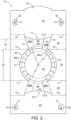
- Figures 1 and 2 show a blank 10 comprising a plurality of panels 12, 14, 16, 18, 20 for forming a tubular structure for surrounding a portion of an article B.
- the plurality of panels 12, 14, 16, 18, 20 includes a main, or base, panel 16 forming an engaging panel 16 of an article engaging device 90 (see Figure 5 ).
- a first side panel 14 is hingedly connected to a first side of the base panel 16 by a hinged connection in the form of a fold line 15.
- a first, or outer, top panel 12 is hingedly connected to the first side panel 14 by a hinged connection in the form of a fold line 13.
- a second side panel 18 is hingedly connected to a second, opposing, side of the base panel 16 by a hinged connection in the form of a fold line 17.
- a second, or inner, top panel 20 is hingedly connected to the second side panel 18 by a hinged connection in the form of a fold line 19.
- the blank 10 is foldable to form a tubular structure as illustrated in Figures 5 and 6 .
- the first and second top panels 12, 20 are engageable with one another in an overlapping relationship to form a composite or two-ply top wall 12/20 of the article engaging device 90.
- the blank 10 may comprise a complementary locking mechanism M/F for securing the second top panel 20 to the first top panel 12.
- the first top panel 12 may comprise at least one first part M of the complementary locking mechanism M/F.
- the second top panel 20 may comprise at least one second part F of the complementary locking mechanism M/F.
- the first top panel 12 comprise a pair of first parts M and a pair of second parts F, each first part M for engaging with a respective one of the pair of second parts F.
- the first top panel 12 comprises a male tab 30.
- the male tab 30 is struck from, or defined in, the first top panel 12 and is hingedly connected thereto by a hinged connection in the form of a fold line 31.
- the second top panel 20 comprises a female tab 32 defining a locking aperture in the second top panel 20.
- the female tab 32 is struck from, or defined in, the second top panel 20 and is hingedly connected thereto by a hinged connection in the form of a fold line 33.
- the locking aperture in the second top panel 20, defined by the female tab 32 is configured to receive the male tab M.
- the female tab F is arranged to be displaced out of the second top panel 20 to form the locking aperture and to bear against the male tab M when received therein.
- a useful mechanical lock may include a heel-and-toe lock, a slide lock, a multi-position plunger lock and the like.
- the locks M/F for securing the top panels 12, 20 together may be replaced by a single lock or three or more locks.
- the locks may be used at any suitable locations on the device depending on the design and structure of the device.
- the device may have an additional side panel hinged to the top panel 12, for placement on the side panel 18 wherein the locks may be located to secure the additional side panel to the underlying side panel 18.
- Such locks should be located such that they do not interfere with the tamper evident device T2.
- the complementary locking mechanism M/F may be omitted; and the first and second top panels 12, 20 may be secured to each other by other means such as but not limited to adhesive or staples.
- the base panel 16 comprises a single article receptacle RT.
- the article receptacle RT comprises an article receiving aperture A1 defined in part by a plurality of engaging teeth 40 and in part by tamperproof tabs T1, T2.
- Each of the plurality of engaging teeth 40 is struck from, or defined in, the base panel 16 and is hingedly connected thereto by a hinged connection in the form of a fold line 41.
- the plurality of engaging teeth 40 define a portion of a perimeter of the article receiving aperture A1.
- the article receiving aperture A1 may be approximately circular or generally polygonal in shape.
- Each tooth 40 comprises a free end edge E3 opposing a hinged edge defined by the fold line 41.
- the free end edges E3 are defined by a linear portion of a cut line defining a portion of the article receiving aperture A1.
- Each free end edge E3 defines a part of a polygon such as but not limited to an icosikaidigon (22-sided polygon).
- the cut line defining the free end edges E3 of the teeth 40 may be arcuate, at least in part, in shape.
- Each tooth 40 comprises a pair of side edges, the side edges are defined by cut lines extending radially outward from respective vertices of the polygon. That is to say from a respective vertex between a pair of adjacent linear portions of the cut line defining the article receiving aperture A1.
- the cut lines are divergently arranged with respect to each other and define an angle therebetween, the angle may be about 16°.
- the article receptacle RT comprises fourteen engaging teeth 40 disposed about the article receiving aperture A1 in two opposing groups of seven engaging teeth 40, each group is spaced apart from each other by a pair of gaps or voids equivalent to around four engaging teeth 40.
- the endmost teeth of each group of teeth 40 may occupy a larger angular dimension than the intermediate teeth disposed therebetween.
- Each group of engaging teeth 40 is arranged to extend about the article receiving aperture A1 across the base panel 16, from a first hinged edge, defined by fold line 15 between the base panel 16 and first side panel 14, to a second hinged edge, defined by fold line 17 between the base panel 16 and second side panel 18.
- the fold lines 41 hinging the engaging teeth to the base panel 16 define a first notional circle NC1, the first notional circle NC1 has diameter equal to twice a first radius r1, which diameter is greater than a lateral dimension or width w1 of the base panel 16.
- the base panel 16 has longitudinal dimension or length which is greater than the diameter of the first notional circle NC1.
- the free end edges E3 of the teeth 40 define a second notional circle NC2, the second notional circle NC2 has diameter equal to twice a second radius r2, which diameter is less than a lateral dimension or width w1 of the base panel 16 and less than the longitudinal dimension or length of the base panel 16.
- the second radius r2 is less than the first radius r1.
- the diameter (twice the first radius r1) of the first notional circle NC1 may be equal to or greater than an external diameter wF of a flange FL of a port or coupling assembly C of an article B, see Figure 3 .
- the diameter (twice the second radius r2) of the second notional circle NC2 may be less than the external diameter wF of the flange FL of the coupling assembly C of the article B.
- the lateral dimension or width w1 of the base panel 16 may be less than the external diameter wF of the flange FL of the coupling assembly C of the article B.
- the article receptacle RT comprises an article receiving aperture A1 that divides the base panel 16 into two separate parts.
- the blank 10 comprises an article securing device for securing the article engaging device 90 to the article B.
- the article securing device comprises at least one cut line (or article-receiving feature) CT1, CT2 defined, at least in part, in one of the first and second side panels 14, 18.
- the illustrated embodiment comprises a pair of cut lines CT1, CT2, a first cut line CT1 is defined, at least in part, in the first side panel 14 and a second cut line CT2 is defined, at least in part, in the second side panel 18.
- the first cut line CT1 extends from the hinged connection, fold line 13, between the first side panel 14 and the first top panel 12.
- the second cut line CT2 extends from the hinged connection, fold line 19, between the second side panel 18 and the second top panel 20.
- Each of the first and second cut line CT1, CT2 is non-linear and may be generally "U” or “C” shaped.
- the first and second cut line CT1, CT2 may be curvilinear or arcuate or may comprise at least two divergently arranged linear sections.
- the cut lines CT1, CT2 comprise a first linear section disposed between a pair of curved sections and a pair of second linear sections.
- Each second linear section extends from a terminal end of one of the pair of curved sections to the respective hinged connection, fold line 13, 19.
- the second linear sections may cross said respective hinged connection, fold line 13, 19 and extend into the respective one of the first and second top panels 12, 20.
- the first cut line CT1 interrupts hinged connection, fold line 13, between the first side panel 14 and the first top panel 12, and defines, at least in part, a first tamperproof tab T1 struck from material which would otherwise form the first side panel 14.
- the first tab T1 is integral with the first top panel 12 and extends outwardly therefrom.
- the second cut line CT2 interrupts hinged connection, fold line 19, between the second side panel 18 and the second top panel 20, and defines, at least in part, a second tab T2 struck from material which would otherwise form the second side panel 18.
- the second tab T2 is integral with the second top panel 20 and extends outwardly therefrom.
- the first cutline CT1 defines a first engaging edge E1 in the first side panel 14.
- the second cutline CT2 defines a second engaging edge E2 in the second side panel 18.
- the first and second engaging edges E1, E2 engage the article B below a flange FL of a coupling assembly C, best shown in Figure 7 .
- Each of the first and second cutlines CT1, CT2 defines, in part, a portion 50 of the respective one of the first and second side panels 14, 18.
- the portions 50 of the first and second side panels 14, 18 provide the first and second engaging edges E1, E2 respectively.
- the first side panel 14 comprises a tamper evident device, the tamper evident device comprises at least two frangible or severable lines 51, 53 defining a tamper evident panel 50A/50/50B provided, at least in part, by the portion 50 of the first side panel 14.
- the tamper evident device comprises a first pair of frangible lines 51 extending substantially across the first side panel 14.
- the first pair of frangible lines 51 extend between the first cut line CT1 and the hinged connection, fold line 15, between the first side panel 14 and the base panel 16.
- the first pair of frangible lines 51 extend to, or close proximity to, the article receptacle RT.
- the first pair of frangible lines 51 may extend into the base panel 16 and interrupt the hinged connection, fold line 15, between the first side panel 14 and the base panel 16 such that a portion of tamper evident panel 50A/50/50B is struck from material which would otherwise form part of the base panel 16.
- a cutline extends between the first pair of frangible lines 51 and defines a lower free edge E4 of the tamper evident panel 50A/50/50B; the cutline may be non-linear, curvilinear or arcuate in shape.
- the cutline defines a portion of a third notional circle NC3, see Figure 2 , the third notional circle NC3 comprises a third radius r3.
- the third radius r3 is greater than the second radius r2 and less than the first radius r1.
- the lower free edge E4 of the tamper evident panel 50A/50/50B lies in a region between the first and second notional circles NC1, NC2.
- the lower free edge E4 defines a tooth free region of the article receptacle RT and defines a portion of the article receiving aperture A1.
- the first pair of frangible lines 51 may be divergently arranged with respect to each other and may diverge towards the first cutline CT1. In this way, the tamper evident panel 50A/50/50B tapers towards the base panel 16.
- Each of the first pair of frangible lines 51 may be collinear, continuous or contiguous, with a cut line defining a side edge of one of the engaging teeth 40 in a respective one of the two groups of engaging teeth 40.
- the tamper evident panel 50A/50/50B may comprise at least one second frangible line 53.
- the tamper evident panel 50A/50/50B may comprise an optional second pair of frangible lines 53.
- the second pair of frangible lines 53 may be divergently arranged with respect to each other.
- the second pair of frangible lines 53 may be divergently arranged with respect to each other and may diverge towards the linear section of the first cutline CT1.
- Each of the second pair of frangible lines 53 may be divergently arranged with respect to one or both of the first pair of frangible lines 51.
- Each of the frangible lines 51, 53 may comprise at least two cutline portions separated from each other by a frangible nick or connecting portion.
- the frangible nick or connecting portions of the first pair of frangible lines 51 couple the tamper evident panel 50A/50/50B to the first side panel 14.
- the frangible nick or connecting portions of the second pair of frangible lines 53 couple the marginal portions 50A of the tamper evident panel 50A/50/50B to a central portion 50 of the tamper evident panel 50A/50/50B.
- each of the frangible lines 51, 53 may comprise three frangible nicks or connecting portions; other embodiments may comprise more or less frangible nicks or connecting portions.
- the second side panel 18, may also comprise a tamper evident device as shown in Figures 1 and 2 ; the tamper evident device in the second side panel 18 is substantially similar in construction to the tamper evident device in the first side panel 14 and will not be described in further detail.
- the blank 10 comprises a third tab T3 integral with the first top panel 12 and extending outwardly from a free side edge of the first top panel 12.
- the free side edge of the first top panel 12 opposes a hinged edge defined by the hinged connection, fold line 13, between the first side panel 14 and the first top panel 12.
- the third tab T3 may be defined in part by a pair of cutlines extending from the free side edge of the first top panel 12 towards the hinged edge. The pair of cutlines being spaced apart from each other and may be linear and perpendicularly oriented to the hinged connection, fold line 13, between the first side panel 14 and the first top panel 12.
- the third tab T3 may be shaped complementary to the second tab T2 and configured to overly the second tab T2 when the blank 10 is in a setup condition.
- the article engaging device 90 can be formed by a series of sequential folding operations.
- the folding process is not limited to that described below and may be altered according to particular manufacturing requirements.
- the blank 10 is brought over an article B and is lowered with respect to the article B, the article receptacle RT being positioned to be in registry or alignment with the coupling assembly C of the article B.
- An upper portion, including flange FL, of the coupling assembly C is received in the article receptacle RT.
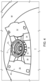
- the plurality of tabs 40 are folded upwardly out of the plane of the base panel 16 as shown in Figure 4 .
- the blank 10 may be tilted or inclined with respect to a horizontal plane, or to a plane defined by the upper surface of the flange FL.
- some of the engaging teeth 40 may be folded out of the plane of the base panels ahead of others.
- the tamper evident panel 50A/50/50B and/or one of both of the side panels 14,18 may bend or distort without severing the connecting nicks to accommodate the coupling assembly C of the article B.
- the second side panel 18 is folded with respect to the base panel 16, about fold line 17, to be disposed about a first side of the coupling assembly C of the article B.
- the second top panel 20 is folded with respect to the second side panel 18, about fold line 19, to be disposed at over at least a portion of the upper end or surface of the coupling assembly C of the article B.
- the second cutline CT2 opens to form an article-receiving feature or receiver opening, in the second side panel 18.
- a portion of the flange FL of the coupling assembly C is received in the receiver opening.
- Second engaging edge E2 engages a lower face of the flange FL. The lower face generally opposes the upper surface of the coupling assembly C over which the second top panel 20 is disposed.
- the first side panel 14 is folded with respect to the base panel 16, about fold line 15, to be disposed about a second side of the coupling assembly C of the article B.
- the first top panel 12 is folded with respect to the first side panel 14, about fold line 13, to be disposed at over at least a portion of the upper end or surface of the coupling assembly C of the article B and in face-to-face relationship with at least a portion of the second top panel 20.
- first cutline CT1 In folding the first top panel 12 with respect to the first side panel 14 the first cutline CT1 opens to form another article-receiving opening or second receiver opening this time in the first side panel 14.
- the receiver openings in the first and second side panels 14, 18 generally oppose each other.
- a second portion of the flange FL of the coupling assembly C is received in the receiver opening in the first side panel 14.
- First engaging edge E1 engages a lower face of the flange FL.
- the first and second top panels 12, 20 are arranged such that each male tab 30 is aligned or in vertical registry with a respective one of the female tabs 32 of the complementary locking mechanism M/F.
- the male tabs 30 are then pressed inwardly out of the plane of the first top panel 12 so as to displace the female tab 32 inwardly of the tubular structure, the male tab 30 is received in the locking aperture created in the second top panel 20, shoulder of the male tab 30 engage an inner or lower surface of the second top panel 20 preventing or at least inhibiting removal of the male tab 30 from the locking aperture thereby securing the first and second panels 12, 20 together.
- the first and second panels 12, 20 may be secured together by alternative means such as mechanical fastenings or adhesive.
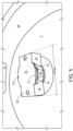
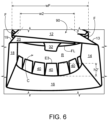
- Figures 5 , 6 and 7 show the assembled article engaging device 90 mounted to the article B.
- Figure 6 shows that the engaging teeth 40 of the article receptacle RT are spaced apart from the lower face of the flange FL of the coupling assembly C.
- the free end edges E3 are disposed at a different, lower, elevation to the engaging edges E1, E2 of the first and second side panels 14,18 and do not interact or engage the lower surface of the flange FL.
- the free end edges E3 of the engaging teeth 40 may engage or contact a side wall R of a neck of the coupling assembly C disposed below the flange FL.
- the neck R may have a lateral dimension or diameter wR (see Figure 3 ) which is greater than twice the second radius r2, and/or greater than the lateral dimension or width w1 of the base panel 16.
- the lateral dimension or diameter wF of the flange FL is greater than the lateral dimension or diameter wR of the neck R.
- the lateral dimension or diameter wR of the neck R is less than twice the first radius r1.
- the lateral dimension or diameter wR of the neck R may be greater than twice the third radius r3.
- the composite top panel 12/20 comprises a lateral dimension or width w2.
- the lateral dimension or width w2 is defined between the hinged connections to the first and second side panels 14, 18, between fold line 13 and fold line 19.
- the lateral dimension or width w2 is less than the lateral dimension or diameter wF of the flange FL.
- the lateral dimension or width w2 of the composite top panel 12/20 may be less than the lateral dimension or width w1 of the base panel 16.
- the flange FL may have lateral dimension or diameter wF of 62mm
- the neck R may have a lateral dimension or diameter wR of 58mm
- the base panel 16 may have a lateral dimension or width w1 of 53mm
- the lateral dimension or diameter between the lower free edges E4 of the tamper evident panels 50A/50/50B in the first and second side panel 14,18 may equal to or greater than 53mm and less than 58mm.
- Figure 8 shows the article engaging device 90 in a state of partial removal from the coupling assembly C of the article B.
- the article engaging device 90 has been moved upwardly relative to the article B.
- This displacement of the article engaging device 90 applies force or pressure to the tamper evident panels 50A/50/50B specifically to the engaging edges E1, E2.
- This force or stress causes at least some of the frangible lines 51, 53 to at least partially break.
- one or both of the tamper evident panels 50A/50/50B is at least partially detached from the respective one of the first and second side panels 14, 18 indicating that the article engaging device 90 has been interfered or tampered with and/or that the coupling assembly C may have been exposed or uncovered and possibly contaminated with dirt or other foreign bodies or that the article B has been previously used to dispense the beverage contained therein.
- FIG. 9 there is shown an additional embodiment of the present disclosure.
- like numerals have, where possible, been used to denote like parts, albeit with the addition of the prefix "100" to indicate that these features belong to the second embodiment.
- the alternative embodiment shares many common features with the embodiment of Figures 1 to 8 , therefore only the differences from the embodiment illustrated in Figures 1 to 8 will be described in any greater detail.
- Figure 9 shows a blank 110 comprising a plurality of main panels 112, 116, 118, 120 including a base panel 116 for forming a base wall or engaging panel 116 of an article engaging device (not shown) and first and second side panels 114, 118; the blank 110 is substantially similar in construction to the blank 10 of Figure 1 albeit the third tab T3 has been omitted.
- Each of the first and second side panels 114, 118 comprise a tamper evident device.
- the tamper evident device is substantially similar in construction to the tamper evident device of Figure 1 albeit a cutline extending between a first pair of frangible lines 151 and defining a lower free edge E4 of a tamper evident panel 150A/150/150B, is linear.
- the cutline may be substantially collinear with a respective one of the hinged connections, fold lines 115, 117, between the base panel 116 and the first and second side panels 114, 118.
- a lower free edge E4 of the tamper evident panel 150A/150/150B lies in a region between first and second notional circles NC1, NC2.
- the lower free edge E4 defines a tooth free region of an article receptacle RT and defines a portion of an article receiving aperture A1.
- the lower free edge E4 of the tamper evident panel 150A/150/150B in the first side panel 114 is spaced apart from the lower free edge E4 of the tamper evident panel 150A/150/150B in the second side panel 118 by a distance equal to the lateral dimension of width w1 of the base panel 112.
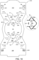
- Figure 10 shows a blank 210 comprising a plurality of panels 212, 214, 216, 218, 220 for forming a tubular structure for surrounding a portion of an article B (see Figure 11 ).
- the plurality of panels 212, 214, 216, 218, 220 includes a main, or base, panel 216 forming an engaging panel 216 of an article engaging device 290 (see Figure 11 and 12 ).
- a first side panel 214 is hingedly connected to a first side of the base panel 216 by a hinged connection in the form of a fold line 215.
- a first, or outer, top panel 212 is hingedly connected to the first side panel 214 by a hinged connection in the form of a fold line 213.
- a second side panel 218 is hingedly connected to a second, opposing, side of the base panel 216 by a hinged connection in the form of a fold line 217.
- a second, or inner, top panel 220 is hingedly connected to the second side panel 218 by a hinged connection in the form of a fold line 219.
- the base panel 216 comprises a single article receptacle RT.
- the article receptacle RT comprises an article receiving aperture A1 defined in part by a plurality of engaging teeth 240 and in part by sensitizing tabs 252, also referred to herein as a sensitizing tab.
- Each of the plurality of engaging teeth 240 is struck from, or defined in, the base panel 216 and is hingedly connected thereto by a hinged connection in the form of a fold line 241.
- the illustrated embodiment comprises a pair of brace tabs 252 disposed opposite each other.
- Each brace tab 252 extends from one of the first and second side panels 214, 218.
- the illustrated embodiment comprises four engaging teeth 240; a pair of engaging teeth 240 is disposed on opposing sides of each of the brace tabs 252.
- the article receptacle RT may comprise a tooth free region disposed between an engaging tooth 240 associated with one of the brace tabs 252 and an engaging tooth 240 associated with the other one of the brace tabs 252.
- the tooth free region may be defined by the aperture A1 and may be defined by a cutline having a linear portion disposed between a pair of arcuate or curved portions.
- Each brace tab 252 is hingedly connected to a portion 250 of the respective one of the first and second side panels 214, 218 by a hinged connection in the form of a fold line 255.
- the blank 210 comprises an article securing device for securing the article engaging device 290 to the article B.
- the article securing device comprises at least one cut line CT1, CT2 defined, at least in part, in one of the first and second side panels 214, 218.
- the illustrated embodiment comprises a pair of cut lines CT1, CT2, a first cut line CT1 is defined, at least in part, in the first side panel 214 and a second cut line CT2 is defined, at least in part, in the second side panel 218.
- the first cut line CT1 extends from the hinged connection, fold line 213, between the first side panel 214 and the first top panel 212.
- the second cut line CT2 extends from the hinged connection, fold line 219, between the second side panel 218 and the second top panel 220.
- Each of the first and second cut line CT1, CT2 is non-linear and may be generally "U” or “C” shaped.
- the first and second cut line CT1, CT2 may be curvilinear or arcuate or may comprise at least two divergently arranged linear sections.
- the cut lines CT1, CT2 comprise a pair of linear sections extending substantially perpendicularly from the respective one of fold lines 213, 219 and an arcuate or curvilinear section disposed between the pair of linear sections.
- Each linear section extends from a terminal end of the curved section to the respective hinged connection, fold line 213, 219.
- the linear sections may cross said respective hinged connection, fold line 213, 219 and extend into the respective one of the first and second top panels 212, 220.
- the first cut line CT1 interrupts hinged connection, fold line 213, between the first side panel 214 and the first top panel 212, and defines, at least in part, a first tamperproof tab T1 struck from material which would otherwise form the first side panel 214.
- the first tab T1 is integral with the first top panel 212 and extends outwardly therefrom.
- the second cut line CT2 interrupts hinged connection, fold line 219, between the second side panel 218 and the second top panel 220, and defines, at least in part, a second tab T2 struck from material which would otherwise form the second side panel 218.
- the second tab T2 is integral with the second top panel 220 and extends outwardly therefrom.
- the first cutline CT1 defines a first engaging edge E1 in the first side panel 214.
- the second cutline CT2 defines a second engaging edge E2 in the second side panel 218.
- the first and second engaging edges E1, E2 engage the article B below a flange FL of an article B, best shown in Figure 12 .
- Each of the first and second cutlines CT1, CT2 defines, in part, a portion 250 of the respective one of the first and second side panels 214, 218.
- the portions 250 of the first and second side panels 214, 218 provide the first and second engaging edges E1, E2 respectively.
- the portions 250 of the first and second side panels 214, 218 provide the first and second engaging edges E1, E2 respectively.
- the first side panel 214 comprises a tamper evident device comprising at least one frangible or severable line 251.
- the tamper evident device comprises at least two frangible or severable lines 251 defining a tamper evident panel 250 provided, at least in part, by the portion 250 of the first side panel 214.
- the tamper evident device comprises a pair of frangible lines 251 extending substantially across the first side panel 214.
- the pair of frangible lines 251 extend between the first cut line CT1 and the hinged connection, fold line 215, between the first side panel 214 and the base panel 216.
- the first pair of frangible lines 251 extend to, or close proximity to, the article receptacle RT.
- the first pair of frangible lines 251 may be divergently arranged with respect to each other and may diverge towards the first cutline CT1. In this way, the tamper evident panel 250 tapers towards the base panel 216.
- the second side panel 218 comprises a tamper evident device comprising at least one frangible or severable line 251.
- the tamper evident device comprises at least two frangible or severable lines 251 defining a tamper evident panel 250 provided, at least in part, by the portion 250 of the second side panel 218.
- the tamper evident device comprises a pair of frangible lines 251 extending substantially across the second side panel 218.
- the pair of frangible lines 251 extend between the second cut line CT2 and the hinged connection, fold line 217, between the second side panel 218 and the base panel 216.
- the first pair of frangible lines 251 extend to, or close proximity to, the article receptacle RT.
- the pairs of frangible lines 251 may be divergently arranged with respect to each other and may diverge towards the first or second cutline CT1, CT2. In this way, the tamper evident panel 250 tapers towards the base panel 216.
- Each brace tab 252 comprises opposed side edges defined, at least in part, by a respective cut line, the cut lines extend from respective ones of the fold lines 215, 217 hinging a side panel 214, 218 to the base panel 216.
- Each cutline is arranged to be contiguous or continuous with one of the frangible lines 251 defining the tamper evident panel 250 in one of the first and second side panels 214, 218.
- Each brace tab 252 comprises an engaging edge E5 for engaging below a flange FL, rim or other suitable projection provided by the article B.
- the blank 210 is foldable to form a tubular structure as illustrated in Figures 11 and 12 .
- the first and second top panels 212, 220 are engageable with one another in an overlapping relationship to form a composite or two-ply top wall 212/220 of the article engaging device 290.
- the blank 210 may comprise a complementary locking mechanism M/F for securing the second top panel 220 to the first top panel 212.
- the first top panel 212 may comprise at least one first part M of the complementary locking mechanism M/F.
- the second top panel 220 may comprise at least one second part F of the complementary locking mechanism M/F.
- the first top panel 212 comprise a pair of first parts M and a pair of second parts F, each first part M for engaging with a respective one of the pair of second parts F.
- the first top panel 212 comprises a male tab 230.
- the male tab 230 is struck from, or defined in, the first top panel 212 and is hingedly connected thereto by a hinged connection in the form of a fold line 231.
- Each male tab 230 is disposed proximate or adjacent to an end edge of the first top panel 212.
- a first one of the pair of male tabs 230 is arranged in opposition to the second one of the pair of male tabs 230, so that the pair of male tabs 230 are mirror images of each other.
- Each male tab 230 is arranged to fold towards the center or middle of the first top panel 212 (away from the end edge of the first top panel 212 that it is proximate to).
- the second top panel 220 comprises a female tab 232 defining a locking aperture in the second top panel 220.
- the female tab 232 is struck from, or defined in, the second top panel 220 and is hingedly connected thereto by a hinged connection in the form of a fold line 233.
- the locking aperture in the second top panel 220, defined by the female tab 232, is configured to receive the male tab M.
- the female tab F is arranged to be displaced out of the second top panel 220 to form the locking aperture and to bear against the male tab M when received therein.
- Each female tab 232 is disposed proximate or adjacent to an end edge of the second top panel 220.
- a first one of the pair of female tabs 232 is arranged in opposition to the second one of the pair of female tabs 232, so that the pair of female tabs 232 are mirror images of each other.
- Each female tab 232 is arranged to fold away from the center or middle of the second top panel 220 (towards the end edge of the second top panel 220 that it is proximate to).
- a female tab 232 is arranged to be in vertical registry with one of the male tabs 230 when the first and second top panels 212, 220 are disposed in overlapping relationship with each other.
- the male and female tabs 230, 232 are provided in regions of the first and second top panels 212, 220 that are unsupported by the article B when the article B is received in the article engaging device 290.
- the male and female tabs 230, 232 are provided in overhanging regions of the first and second top panels 212, 220, the overhanging regions extend from the flange FL which is disposed at an upper end of a neck portion R of the article B.
- the overhanging regions extend over the base panel 216 and over the top T of the article B from which the neck portion R of coupling assembly extends.
- Each male tab 230 comprises a head and a shaft, the shaft couples the head to the first top panel 212.
- the head may comprise a pair of partial depth cutlines 235.
- the partial depth cutlines 235 extend partially through the substrate forming the blank 210, such that wing portions 230a of the head are coupled to a medial portion of the head by a weakened line or connection.
- the partial depth cutlines 235 may be defined in an upper or outer surface of the first top panel 212.
- Each partial depth cutline 235 may be collinear with a cut line defining a side edge of the shaft of the male tabs 230.
- the partial depth cutlines 235 provide a tamper evident structure to indicate whether the male tabs 230 have been disengaged from the second top panel 220, or otherwise interfered with, following their initial engagement with the second top panel 220 to secure the first and second top panels 212, 220 together.
- the partial depth cutlines 235 open or tear, at least in part, when withdrawal of the male tabs 230 from their respective locking aperture in the second top panel 220 is attempted.
- One or both of the wing portions 230a of the male tabs 230 may be severed or partially detached from the medial portion of the head so as to provide a visual indication that the complementary locking mechanism M/F may have been interfered or tampered with.
- the outer or upper surface of the substrate may be a coated or printed surface.
- Providing the partial depth cutlines 235 on an outer or upper surface of the substrate may have the effect of weakening the male tabs 230 to a greater extent in a first condition in which forces are applied to the male tabs 230 which have the effect of folding the inner or lower surface of the wing portions 230a towards the inner or lower surface of the medial portion of the head compared to a second condition in which a forces are applied to the male tabs 230 which have the effect of folding the outer or upper surface of the wing portions 230a towards the outer or upper surface of the medial portion of the head.
- the forces applied have the effect of closing the partial depth cutlines 235, edges of the substrate.
- the wing portions 230a may be able to fold with respect to the medial portion of the head without tears propagating in the substrate.
- the forces applied have the effect of opening the partial depth cutlines 235 which may encourage tears to propagate in the substrate.
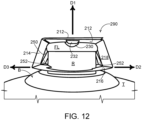
- FIGs 11 and 12 show the article engaging device 290 engaged with an article B
- the brace tabs 252 are folded with respect to the tamper evident panel 250 to which they are hinged so as to be substantially in face-to-face relationship with each other, that is to say the brace tabs 252 and the tamper evident panel 250 defined an acute angle therebetween and may be disposed in face contacting relationship with each other.
- the brace tabs 252 have the effect of sensitizing the tamper evident panels 250 to movement of the article engaging device 290 with respect to the article B with which it is engaged.
- the brace tabs 252 in turn force a lower edge, the hinged edge defined by fold line 255 of the tamper evident panels 250 outwardly as indicated by direction arrows D2, D3, this creates a shearing force between tamper evident panels 250 and the adjacent portions of the side panels 214, 218 breaking the frangible lines 251 and detaching the tamper evident panels 250 from the article engaging device 290.
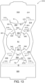
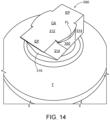
- Figure 13 shows a blank 310 comprising a plurality of panels 312, 314, 316, 318, 320 for forming a tubular structure for surrounding a portion of an article B (see Figure 14 ).
- the plurality of panels 312, 314, 316, 318, 320 includes a main, or base, panel 316 forming an engaging panel 316 of an article engaging device 390 (see Figure 14 ).
- the blank 310 is substantially similar in construction to the blank 210 of Figure 10 albeit the complementary locking mechanism M/F has been omitted and second top panel 320 comprises a glue region G, application of glue or other adhesive treatment to the glue region G or to a corresponding portion of the first top panel 312 enables the first top panel 312 to be secured to the second top panel 320.
- the present disclosure provides an article engaging device 90 of the top engaging type having article receptacle RT for engaging an article B and a blank 10; 110 for forming the article engaging device 90.
- the present disclosure also provides a combination of at least one article B and an article engaging device 90, in which the article engaging device 90 is in engagement with the at least one article B.
- the article engaging device 90 comprises a plurality of primary panels 12, 14, 16, 18, 20; 112, 114, 116, 118, 120 hingedly connected one to another such that the plurality of primary panels 12, 14, 16, 18, 20; 112, 114, 116, 118, 120form a tubular structure in which a part C of the at least one article B is received.
- the plurality of panels 12, 14, 16, 18, 20; 112, 114, 116, 118, 120 comprises a first panel 16; 116 having an article receptacle RT through which the part C of the at least one article B is received in the tubular structure.
- the article engaging device 90 defines a footprint which is less than a footprint of the at least one article B.
- the area of the first panel 16; 116 may be less than the area of the upper end of the article B to which the article engaging device 90 is applied.
- the article engaging device 90 may have a first maximum horizontal or footprint dimension, a maximum length or width wmax (see Figure 5 ), the at least one article B comprises a single article B having a second maximum horizonal or footprint dimension, a maximum length, width or diameter wB (see Figure 3 ).
- the second maximum horizonal or footprint dimension wB may be greater than the first maximum horizontal or footprint dimension wmax.
- the present disclosure also provides an article engaging device 90 for engaging at least one article B.
- the article engaging device 90 comprises a plurality of primary panels 12, 14, 16, 18, 20; 112, 114, 116, 118, 120 hingedly connected one to another such that the plurality of primary panels 12, 14, 16, 18, 20; 112, 114, 116, 118, 120 form a tubular structure in which a part of the at least one article B is receivable.
- the plurality of panels 12, 14, 16, 18, 20; 112, 114, 116, 118, 120 comprises a first panel 14, 18; 114, 118 having a first article-receiving feature CT1, CT2 for receiving a part C of at least one article B.
- the article engaging device 90 further comprises a tamperproof structure which comprises a frangible area 50A/50/50B; 150A/150/150B including three or more severance lines 51, 53; 151, 153 each extending from the first article-receiving feature CT1, CT2.
- a tamperproof structure which comprises a frangible area 50A/50/50B; 150A/150/150B including three or more severance lines 51, 53; 151, 153 each extending from the first article-receiving feature CT1, CT2.
- the plurality of panels 12, 14, 16, 18, 20; 112, 114, 116, 118, 120 may comprise a second panel 16; 116 having an article receptacle RT for receiving a part C of at least one article B.
- Each of the three or more severance lines 51, 53; 151, 153 may extend between the first article-receiving feature CT1, CT2 and the article receptacle RT.
- Each of the three or more severance lines 51, 53; 151, 153 may be provided by a perforation comprising a series of slits in at least the first panel 14, 18; 114, 118.
- the three or more severance lines comprise at least one weakened line (for example, but not limited to, a fold line or a severance line) and a pair of severance lines 51; 151.
- the pair of severance lines 51; 151 partially define the frangible area 50A/50/50B; 150A/150/150B.
- the at least one weakened line is disposed between the pair of severance lines 51; 151.
- the present disclosure also provides an article engaging device 90 for engaging at least one article B, the article engaging device 90 comprising a plurality of panels 12, 14, 16, 18, 20; 112, 114, 116, 118, 120 hingedly connected one to another such that the plurality of panels 12, 14, 16, 18, 20; 112, 114, 116, 118, 120 form a tubular structure in which a part C of the at least one article B is received.
- the plurality of panels 12, 14, 16, 18, 20; 112, 114, 116, 118, 120 includes a pair of opposed side panels 14, 18; 114, 118 and a base panel 16; 116.
- a first one of the pair of opposed side panels 14, 18; 114, 118 comprises an article-receiving feature CT1, CT2 for receiving a part C of at least one article B.
- the article engaging device 90 further comprises a tamperproof tab 50A/50/50B; 150A/150/150B which comprises an upper edge E1, E2 defining in part the article-receiving feature CT1, CT2.
- the upper edge E1, E2 being located at a first distance h1; h1' from the base panel 16; 116, or from a hinged connection, fold line 15, 17; 115, 117 between the first one of the pair of opposed side panels 14, 18; 114, 118 and the base panel 16; 116.
- the base panel 16; 116 comprises an entrance or article receptacle RT through which a part C of at least one article B is receivable in the tubular structure.
- the entrance or article receptacle RT comprises an engaging tooth 40; 140.
- the engaging tooth 40; 140 has a proximal end 41; 141 hingedly connected to the base panel 16; 116 and extends to an opposed distal end E3.
- the distal end E3 is located at a second distance h2; h2' from the base panel 16; 116, or from the proximal end 41; 141.
- the first distance h1; h1' is greater than the second distance h2, h2'.
- the present disclosure also provides an article engaging device 90 for engaging at least one article.
- the article engaging device 90 comprises a plurality of panels 12, 14, 16, 18, 20; 112, 114, 116, 118, 120 hingedly connected one to another such that the plurality of panels 12, 14, 16, 18, 20; 112, 114, 116, 118, 120 form a tubular structure in which a part C of the at least one article B is received.
- the plurality of panels 12, 14, 16, 18, 20; 112, 114, 116, 118, 120 includes a pair of opposed side panels 14, 18; 114, 118, each of the pair of opposed side panels 14, 18; 114, 118 comprises an article-receiving feature CT1, CT2 for receiving a part C of at least one article B.
- the article engaging device 90 further comprises a pair of tamperproof tabs 50A/50/50B; 150A/150/150B each comprising an upper edge E1, E2 defining in part a respective one of the article-receiving features CT1, CT2.
- the pair of tamperproof tabs 50A/50/50B; 150A/150/150B are opposed to each other across an entrance or article receptacle RT in the base panel 16; 116 through which a part C of at least one article B is receivable in the tubular structure.
- the present disclosure also provides a panel-interlocking device M/F for securing a pair of panels 212, 220.
- the panel-interlocking device M/F comprises a first engaging element F provided by one of the pair of panels 212, 220 for engaging with a second engaging element M provided by the other of the pair of panels 212, 220.
- the second engaging element M comprises a male tab 230 hingedly connected to the other of the pair of panels 212, 220.
- the first engaging element F comprises a locking aperture in said one of the pair of panels 212, 220 for receiving at least a portion of the male tab 230.
- the male tab 230 comprises at least one tamperproof element 230a connected to the remainder of the male tab 230 by a frangible connection 235.
- the frangible connection 235 comprises at least one frangible line 235 which is formed of one selected from the group consisting of: a partial cut, a line of partial cuts, and a line of one or more perforations.
- the at least one tamperproof element 230a comprises a two or more tamperproof elements 230a each frangibly connected to the remainder of the male tab 230 by the frangible connection 235.
- the at least one frangible line 235 comprises a partial cut that is formed by cutting a coated, or outer, side of the sheet material from which at least the other of the pair of panels is formed.
- the panel-interlocking device of the present disclosure is useful with cartons and carton blanks other than those disclosed in the present disclosure.
- cartons and carton blanks include wraparound carriers, basket carriers, tubular top engaging carriers and their blanks formed from a sheet material, which requires two panel portions thereof to be interconnected in an overlapping arrangement.
- the present disclosure provides an article engaging device 290; 390 and/or blank 210; 310 for forming the same.
- the article engaging device 290; 390 comprises primary panels 212, 214, 216, 218, 220; 312, 314, 316, 318, 320 for forming a tubular structure in which part of an article B is receivable.
- the primary panels 212, 214, 216, 218, 220; 312, 314, 316, 318, 320 comprise a first panel 216; 316 having an article receptacle RT and a second panel 214, 218; 314, 318 hingedly connected to the first panel 216; 316.
- the article engaging device 290; 390 (or blank 210; 310) further comprises a frangible area 250; 350 provided, at least in part, by the second panel 214, 218; 314, 318 and a sensitizing tab 252; 352 connected to the frangible area 250; 350.
- the sensitizing tab 252; 352 extends into the tubular structure to engage part of the article B. In blank form the sensitizing tab 252; 352 extends into the article receptacle RT.
- the sensitizing tab 252; 352 extends between the frangible area 250; 350 and the part of the article B when the part of the article B is received in the article receptacle RT.
- the primary panels 212, 214, 216, 218, 220; 312, 314, 316, 318, 320 further comprise a third panel 212, 220; 312, 320 hingedly connected to the second panel 214, 218; 314, 318 along an edge of the second panel 214, 218; 314, 318 opposing the hinged connection to the first panel 216; 316.
- the frangible area 250; 350 comprises a tamperproof tab 250; 350 defined by at least a pair of opposing frangible lines 251; 351 on the second panel 214, 218; 314, 318 each extending from the sensitizing tab 252; 352 toward the third panel 212, 220; 312, 320.
- the tamperproof tab 250; 350 comprises an engaging end E1, E2 for engaging the part of the article B.
- the engaging end E1, E2 is disposed opposite to an end of the tamperproof tab 250; 350 connected to the sensitizing tab 252; 352.
- the pair of opposing frangible lines 251; 351 extend divergently from the sensitizing tab 252; 352 to the engaging end E1, E2.
- the present disclosure also provides an article engaging device 290 comprising primary panels 212, 214, 216, 218, 220 for forming a tubular structure in which part of an article B is receivable.
- the primary panels 212, 214, 216, 218, 220 comprise a base panel 216 having an article receptacle RT and a top wall 212/220 disposed above the base panel 216.
- the top wall 212/220 is formed at least of a pair of inner and outer overlapping panels 212, 220 and comprises an article covering area CA (see Figure 11 and 14 ) disposed directly above the article receptacle RT.
- the top wall 212/220 comprises a pair of opposed end portions EP extending in opposite directions from the covering area CA to respective terminal ends of the top wall 212/220 such that a void space extends between the base panel 216 and each of the end portions EP.
- the article engaging device 290 further comprises a pair of panel-interlocking devices M/F for securing the inner and outer overlapping panels 212, 220 in face-contacting arrangement.
- the panel-interlocking devices M/F are disposed on the end portions EP of the top wall 212/220, respectively.
- the pair of panel-interlocking devices M/F define a notional line N1-N1 (see Figure 11 ) passing through both the panel-interlocking devices M/F and parallel to a tubular axis of the tubular structure, and wherein the notional line intersects the covering area CA.
- Each of the panel-interlocking devices M/F comprises a locking aperture defined in the inner panel 220 for receiving a locking tab 230 formed from the outer panel 212.
- hinged connection and “fold line” refer to all manner of lines that define hinge features of the blank, facilitate folding portions of the blank with respect to one another, or otherwise indicate optimal panel folding locations for the blank. Any reference to “hinged connection” should not be construed as necessarily referring to a single fold line only; indeed, a hinged connection can be formed from two or more fold lines wherein each of the two or more fold lines may be either straight/linear or curved/curvilinear in shape. When linear fold lines form a hinged connection, they may be disposed parallel with each other or be slightly angled with respect to each other.
- curvilinear fold lines When curvilinear fold lines form a hinged connection, they may intersect each other to define a shaped panel within the area surrounded by the curvilinear fold lines.
- a typical example of such a hinged connection may comprise a pair of arched or arcuate fold lines intersecting at two points such that they define an elliptical panel therebetween.
- a hinged connection may be formed from one or more linear fold lines and one or more curvilinear fold lines.
- a typical example of such a hinged connection may comprise a combination of a linear fold line and an arched or arcuate fold line which intersect at two points such that they define a half-moon shaped panel therebetween.
- fold line may refer to one of the following: a scored line, an embossed line, a debossed line, a line of perforations, a line of short slits, a line of half-cuts, a single half-cut, an interrupted cutline, a line of aligned slits, a line of scores and any combination of the aforesaid options.
- hinged connections and fold lines each can include line elements that are formed in the substrate of the blank including perforations, a line of perforations, a line of short slits, a line of half-cuts, a single half-cut, a cutline, an interrupted cutline, slits, scores, embossed lines, debossed lines, any combination thereof, and the like.
- the line elements can be dimensioned and arranged to provide the desired functionality.
- a line of perforations can be dimensioned or designed with degrees of weakness to define a fold line and/or a severance line.
- the line of perforations can be designed to facilitate folding and resist breaking, to facilitate folding and facilitate breaking with more effort, or to facilitate breaking with little effort.
- in registry with and in vertical registry with refers to the alignment of two or more elements in an erected carton, such as an aperture formed in a first of two overlapping panels and an aperture formed in a second of two overlapping panels. Those elements in registry with each other may be aligned with each other in the direction of the thickness of the overlapping panels.
- an edge of the first aperture may extend along at least a portion of an edge of the second aperture and may be aligned, in the direction of the thickness of the first and second panels, with the at least a portion of the edge of the second aperture.
- the first aperture in the first panel when "in vertical registry with” the second aperture in the second panel may be disposed above or over the second aperture when the carton or carrier is in a normal or resting condition (or as shown in the illustrated embodiment), but it will be understood that the carton or carrier is not limited to such an orientation.
Landscapes
- Engineering & Computer Science (AREA)
- Mechanical Engineering (AREA)
- Packages (AREA)
- Clamps And Clips (AREA)
Abstract
Description
- The present invention relates to article engaging structures and blanks for forming the same. More specifically, but not exclusively, the invention relates to an article engaging device of the top-gripping type having one aperture for receiving and retaining a portion of article therein.
- In the beverage industry, it is well known to provide an article in the form of a keg or barrel to store, transport, and serve a beverage. The keg or barrel typically comprises multiple servings of the beverage such as but not limited to beer. Other alcoholic or non-alcoholic drinks, carbonated or non-carbonated, may be housed within the keg. Beer kegs are typically made of stainless steel, or aluminum, and have a single opening in one end, called a "bung" or "bunghole". A tube called a "spear" extends from the opening to the other end. The keg comprises a port having self-closing valve that is opened by a coupling fitting which is attached when the keg is "tapped". There is also an opening at the top of the spear that allows a propulsion gas, such as carbon dioxide, to propel the beer out of the keg to a tap or faucet. The coupling fitting may have at least one valve for controlling the flow of the beverage out of the keg and controlling flow of the propulsion gas into the keg. The keg must be in the upright position, that is, with the opening or "bunghole" on top, for the beer to be dispensed. The bunghole at the top of the keg is used to clean and fill the keg. The opening in the keg is sealed with a coupling assembly which includes the self-closing valve which may comprise a ball bearing which acts as a stopper or valve to retain the fluids, beverage and gas, in the keg. The ball bearing is held in place by the fluid pressure inside the keg. The coupling fitting or "tap" is the port or coupling assembly atop the keg and a lever may be employed to provide the mechanical force sufficient to press or displace the ball bearing downwardly or inwardly, whereby providing access to the keg's contents.
- It is desirable to protect the coupling assembly or port of a keg or other similar article such as, but not limited to, water cooler or dispenser bottles, to prevent ingress of dirt or dust while the keg or similar is transported and stored. It is also desirable to provide information, indicia or branding that is readily visible. It is desirable to provide evidence that the dust cap or cover has been tampered with or otherwise removed after its initial application to an article such as a keg.
- It is an object of the present invention to provide a cover, formed from paperboard or the like, to protect an upper end of the article and/or to provide a display panel for display of information.
- It is an object of the present invention to provide a tamper evident device to indicate if a packaging structure or article engaging device, in particular a securing device retaining a pair of panels in overlapping relationship, has been interfered with.
- It is also desirable that the cover may be readily recycled and/or formed from recycled material.
- The present invention seeks to provide an improvement in the field of dust caps or covers for articles such as kegs, large liquid bottles and water dispensers.
- A first aspect of the invention provides a combination of at least one article and an article engaging device, in which the article engaging device is in engagement with the at least one article. The article engaging device comprises a plurality of primary panels hingedly connected one to another such that the plurality of primary panels forms a tubular structure in which a part of the at least one article is received. The plurality of panels comprises a first panel having an article receptacle through which the part of the at least one article is received in the tubular structure. The article engaging device defines a footprint which is less than a footprint of the at least one article.
- Optionally, the area of the first panel is less than the area of an upper end of the article to which the article engaging device is applied.
- Optionally, the article engaging device has a first maximum horizontal dimension and the at least one article comprises a single article having a second maximum horizonal dimension, the second maximum horizonal dimension is greater than the first maximum horizontal dimension.
- Optionally, the article engaging device has a first maximum footprint dimension, the at least one article comprises a single article having a second maximum footprint dimension, the second maximum footprint dimension is greater than the first maximum footprint dimension.
- A second aspect of the invention provides an article engaging device for engaging at least one article. The article engaging device comprises a plurality of primary panels hingedly connected one to another such that the plurality of primary panels forms a tubular structure in which a part of the at least one article is receivable. The plurality of panels comprises a first panel having a first article-receiving feature for receiving a part of at least one article. The article engaging device further comprises a tamperproof structure which comprises a frangible area including three or more severance lines each extending from the first article-receiving feature.
- Optionally, the plurality of panels comprises a second panel having an article receptacle for receiving a part of at least one article, each of the three or more severance lines extends between the first article-receiving feature and the article receptacle.
- Optionally, each of the three or more severance lines is provided by a perforation comprising a series of slits in at least the first panel.
- Optionally, the three or more severance lines comprises at least one weakened line and a pair of severance lines, the pair of severance lines partially define the frangible area, the at least one weakened line is disposed between the pair of severance lines.
- Optionally, the at least one weakened line is a fold line or a severance line.
- A third aspect of the invention provides an article engaging device for engaging at least one article. The article engaging device comprises a plurality of panels hingedly connected one to another such that the plurality of panels forms a tubular structure in which a part of the at least one article is receivable. The plurality of panels includes a pair of opposed side panels and a base panel. A first one of the pair of opposed side panels comprises an article-receiving feature for receiving a part of at least one article. The article engaging device further comprises a tamperproof tab having an upper edge defining in part the article-receiving feature. The upper edge is located at a first distance from the base panel. The base panel comprises an article receptacle through which a part of at least one article is receivable in the tubular structure. The article receptacle comprises an engaging tooth. The engaging tooth has a proximal end hingedly connected to the base panel and extends to an opposed distal end. The distal end is located at a second distance from the base panel. The first distance is greater than the second distance.
- A fourth aspect of the invention provides an article engaging device for engaging at least one article. The article engaging device comprises a plurality of panels hingedly connected one to another such that the plurality of panels forms a tubular structure in which a part of the at least one article is receivable. The plurality of panels includes a pair of opposed side panels and a base panel. A first one of the pair of opposed side panels comprises an article-receiving feature for receiving a part of at least one article. The article engaging device further comprises a tamperproof tab having an upper edge defining in part the article-receiving feature. The upper edge is located at a first distance from a hinged connection between the first one of the pair of opposed side panels and the base panel. The base panel comprises an article receptacle through which a part of at least one article is receivable in the tubular structure. The article receptacle comprises an engaging tooth. The engaging tooth has a proximal end hingedly connected to the base panel and extends to an opposed distal end. The distal end is located at a second distance from the proximal end. The first distance is greater than the second distance.
- A fifth aspect of the invention provides an article engaging device for engaging at least one article. The article engaging device comprises a plurality of panels hingedly connected one to another such that the plurality of panels forms a tubular structure in which a part of the at least one article is receivable. The plurality of panels includes a pair of opposed side panels and a base panel. Each of the pair of opposed side panels comprises an article-receiving feature for receiving a part of at least one article. The article engaging device further comprises a pair of tamperproof tabs each comprising an upper edge defining in part a respective one of the article-receiving features. The pair of tamperproof tabs are opposed to each other across an article receptacle in the base panel through which a part of at least one article is receivable in the tubular structure.
- A sixth aspect of the invention provides a tamper evident dust cap for protecting a port of an article comprising the article engaging device.
- Optionally, the article is a keg for a beverage.
- A seventh aspect of the invention provides a blank for forming an article engaging device. The blank comprises a plurality of primary panels hingedly connected one to another for forming a tubular structure in which a part of the at least one article is receivable. The plurality of panels comprises a first panel having a first article-receiving feature for receiving a part of at least one article. The article engaging device further comprises a tamperproof structure which comprises a frangible area including three or more severance lines each extending from the first article-receiving feature.
- An eighth aspect of the invention provides a blank for forming an article engaging device. The blank comprises a plurality of panels hingedly connected one to another for forming a tubular structure in which a part of the at least one article is receivable. The plurality of panels includes a pair of opposed side panels and a base panel. A first one of the pair of opposed side panels comprises an article-receiving feature for receiving a part of at least one article. The article engaging device further comprises a tamperproof tab having an upper edge defining in part the article-receiving feature. The base panel comprises an article receptacle through which a part of at least one article is receivable in the tubular structure. The article receptacle comprises an engaging tooth The engaging tooth has a proximal end hingedly connected to the base panel and extends to an opposed distal end. In a setup condition, the upper edge is located at a first distance from the base panel and the distal end of the engaging tooth is located at a second distance from the base panel. The first distance is greater than the second distance.
- A ninth aspect of the invention provides a blank for forming an article engaging device. The blank comprises a plurality of panels hingedly connected one to another for forming a tubular structure in which a part of the at least one article is receivable. The plurality of panels includes a pair of opposed side panels and a base panel. A first one of the pair of opposed side panels comprises an article-receiving feature for receiving a part of at least one article. The article engaging device further comprises a tamperproof tab having an upper edge defining in part the article-receiving feature. The base panel comprises an article receptacle through which a part of at least one article is receivable in the tubular structure. The article receptacle comprises an engaging tooth. The engaging tooth has a proximal end hingedly connected to the base panel and extends to an opposed distal end. The upper edge of the tamperproof tab is located at a first distance from a hinged connection between the first one of the pair of opposed side panels and the base panel. The distal end of the engaging tooth is located at a second distance from the proximal end. The first distance is greater than the second distance.
- A tenth aspect of the invention provides a blank for forming an article engaging device. The blank comprises a plurality of panels hingedly connected one to for forming a tubular structure in which a part of the at least one article is receivable. The plurality of panels includes a pair of opposed side panels and a base panel. Each of the opposed side panels comprises an article-receiving feature for receiving a part of at least one article. The article engaging device further comprises a pair of tamperproof tabs each comprising an upper edge defining in part a respective one of the article-receiving features. The pair of tamperproof tabs are opposed to each other across an article receptacle in the base panel through which a part of at least one article is receivable in the tubular structure.
- Optionally, the device or blank is recyclable.
- Optionally, the device or blank is formed of a printable sheet material.
- Optionally, the plurality of panels includes a pair of top panels secured together in a face-contacting arrangement.
- Optionally, the top panels are secured together by a mechanical lock.
- An eleventh aspect of the invention provides a panel-interlocking device for securing a pair of panels. The panel-interlocking device comprises a first engaging element provided by one of the pair of panels for engaging with a second engaging element provided by the other of the pair of panels. The second engaging element comprises a male tab hingedly connected to the other of the pair of panels. The first engaging element comprises a locking aperture in said one of the pair of panels for receiving at least a portion of the male tab. The male tab comprises at least one tamperproof element connected to the remainder of the male tab by a frangible connection.
- Optionally, the frangible connection comprises at least one frangible line which is formed of one selected from the group consisting of: a partial cut, a line of partial cuts, and a line of one or more perforations.
- Optionally, the at least one tamperproof element comprises a two or more tamperproof elements each frangibly connected to the remainder of the male tab by the frangible connection.
- Optionally, the at least one frangible line comprises a partial cut that is formed by cutting a coated side of the sheet material from which at least the other of the pair of panels is formed.
- Optionally, the at least one frangible line comprises a partial cut that is formed by cutting an outer side of the sheet material from which at least the other of the pair of panels is formed.
- A twelfth aspect of the invention provides an article engaging device for engaging at least one article. The article engaging device comprises primary panels for forming a tubular structure in which part of an article is receivable. The primary panels comprise a first panel having an article receptacle and a second panel hingedly connected to the first panel. The article engaging device further comprises a frangible area provided, at least in part, by the second panel and wherein a sensitizing tab is connected to the frangible area. The sensitizing tab extends into the tubular structure to engage part of the article. The sensitizing tab extends between the frangible area and the part of the article when the article is received in the article receptacle.
- Optionally, the primary panels further comprise a third panel hingedly connected to the second panel along an edge of the second panel opposing the hinged connection to the first panel, the frangible area comprises a tamperproof tab defined by at least a pair of opposing frangible lines in the second panel each extending from the sensitizing tab toward the third panel, the tamperproof tab comprises an engaging end for engaging the part of the article, the engaging end is disposed opposite to an end of the tamperproof tab connected to the sensitizing tab.
- Optionally, the pair of opposing frangible lines extend divergently from the sensitizing tab to the engaging end.
- Optionally, the sensitizing tab is hingedly connected to the frangible area and defines an acute angle with respect to the frangible area when the article is received in the article receptacle.
- Optionally, the sensitizing tab is hingedly connected to the frangible area by at least one fold line.
- A thirteenth aspect of the invention provides a blank for forming article engaging device. The blank comprises primary panels for forming a tubular structure in which part of an article is receivable. The primary panels comprise a first panel having an article receptacle and a second panel hingedly connected to the first panel. The blank further comprises a frangible area provided, at least in part, by the second panel. A sensitizing tab is hingedly connected to the frangible area. The sensitizing tab extends from the frangible area into the article receptacle. The sensitizing tab extends between the frangible area and the part of the article when the part of the article is received in the article receptacle.
- Optionally, the article receptacle comprises an engaging tooth, the engaging tooth having a proximal end hingedly connected to the first panel and extending to an opposed distal end. The sensitizing tab may extend into the article receptacle beyond the distal end of engaging tooth.
- Optionally, the sensitizing tab is hingedly connected to the frangible area by a fold line and extends from the fold line to an opposed engaging edge. The engaging edge of the sensitizing tab may be located at a first distance from the fold line. The article receptacle may comprise an engaging tooth having a proximal end hingedly connected to the first panel. The engaging tooth may extend to a distal end opposite to the proximal end. The distal end of the engaging tooth may be located at a second distance from its proximal end. The first distance may be greater than the second distance.
- A fourteenth aspect of the invention provides an article engaging device comprising primary panels for forming a tubular structure in which part of an article is receivable. The primary panels comprise a base panel having an article receptacle and a top wall disposed above the base panel. The top wall is formed at least of a pair of inner and outer overlapping panels and comprises an article covering area disposed directly above the article receptacle. The top wall comprises a pair of opposed end portions extending in opposite directions from the covering area to respective terminal ends of the top wall such that a void space extends between the base panel and each of the end portions. The article engaging device further comprises a pair of panel-interlocking devices for securing the inner and outer overlapping panels in face-contacting arrangement, the panel-interlocking devices are disposed on the end portions of the top wall respectively.
- Optionally, the pair of panel-interlocking devices define a notional line passing through both the panel-interlocking devices and parallel to a tubular axis of the tubular structure, and wherein the notional line intersects the covering area.
- Optionally, each of the panel-interlocking devices comprises a locking aperture defined in the inner panel for receiving a locking tab formed from the outer panel.
- A fifteenth aspect of the invention provides a blank for forming article engaging device. The blank comprises a plurality of panels and a panel-interlocking device for securing first and second panels of the plurality of panels. The panel-interlocking device comprises a first engaging element provided by the first panel for engaging with a second engaging element provided by the second panel. The second engaging element comprises a male tab hingedly connected to the second panel. The first engaging element comprises a locking aperture in the first panel for receiving at least a portion of the male tab. The male tab comprises at least one tamperproof element connected to the remainder of the male tab by a frangible connection.
- Further features and advantages of the present invention will be apparent from the specific embodiments illustrated in the drawings and discussed below.
- Within the scope of this application, it is envisaged or intended that the various aspects, embodiments, examples, features and alternatives set out in the preceding paragraphs, in the claims and/or in the following description and drawings may be considered or taken independently or in any combination thereof.
- Features or elements described in connection with, or relation to, one embodiment are applicable to all embodiments unless there is an incompatibility of features. One or more features or elements from one embodiment may be incorporated into, or combined with, any of the other embodiments disclosed herein, said features or elements extracted from said one embodiment may be included in addition to, or in replacement of one or more features or elements of said other embodiment.
- A feature, or combination of features, of an embodiment disclosed herein may be extracted in isolation from other features of that embodiment. Alternatively, a feature, or combination of features, of an embodiment may be omitted from that embodiment.
- Exemplary embodiments of the invention will now be described with reference to the accompanying drawings, in which:
-
Figures 1 and2 are plan views from above of a blank for forming an article engaging device, cover or dust cap according to an embodiment of the present disclosure; -
Figure 3 is a perspective view from above of an article for use with the blank ofFigure 1 ; -
Figure 4 shows a stage of construction of the article engaging device from the blank ofFigure 1 ; -
Figure 5 is a perspective view from above of the article engaging device mounted to the article ofFigure 3 ; -
Figure 6 is a perspective end view of the article engaging device ofFigure 5 ; -
Figure 7 is an enlarged perspective view of the article engaging device ofFigure 5 ; -
Figure 8 is a perspective view from above of the article engaging device showing a tamper evident device indicating the article engaging device has been tampered with; -
Figure 9 is a plan view from above of a blank for forming an article engaging device, cover or dust cap according to another embodiment of the present disclosure; -
Figure 10 is a plan view from above of a blank for forming an article engaging device, cover or dust cap according to a further embodiment of the present disclosure; -
Figure 11 is a perspective view from above of an article engaging device formed from the blank ofFigure 10 mounted to an article; -
Figure 11 is a perspective end view of the article engaging device ofFigure 10 ; -
Figure 12 is a plan view from above of a blank for forming an article engaging device, cover or dust cap according to yet another embodiment of the present disclosure; -
Figure 13 is a perspective view from above of an article engaging device formed from the blank ofFigure 12 mounted to an article; -
Figure 14 is a perspective view from above of an article engaging device formed from the blank ofFigure 13 mounted to an article. - Detailed descriptions of specific embodiments of article engaging devices, packages, and blanks are disclosed herein. It will be understood that the disclosed embodiments are merely examples of the way in which certain aspects of the invention can be implemented and do not represent an exhaustive list of all of the ways the invention may be embodied. As used herein, the word "exemplary" is used expansively to refer to embodiments that serve as illustrations, specimens, models, or patterns. Indeed, it will be understood that the article engaging devices, packages, and blanks, and carriers described herein may be embodied in various and alternative forms. The Figures are not necessarily to scale and some features may be exaggerated or minimized to show details of particular components. Well-known components, materials or methods are not necessarily described in great detail in order to avoid obscuring the present disclosure. Any specific structural and functional details disclosed herein are not to be interpreted as limiting, but merely as a basis for the claims and as a representative basis for teaching one skilled in the art to variously employ the invention.
- Referring to
Figure 1 , there is shown a plan view of a blank 10 which is capable of forming an article engaging device, dust cap or cover 90, as shown inFigure 5 , for use with a keg or barrelB. Alternative blanks 110; 210; 310 for formingarticle engaging devices 290; 390 according to further embodiments of the disclosure are shown inFigures 9 ,10 , and12 . - The
blanks 10; 110; 210; 310 are formed from a sheet of suitable substrate. It is to be understood that, as used herein, the term "suitable substrate" includes all manner of foldable sheet material such as paperboard, corrugated board, cardboard, plastic, combinations thereof, and the like. It should be recognized that one or other numbers of blanks may be employed, where suitable, for example, to provide the carrier, carton or device described in more detail below. - The
packaging structures 90; 290; 390 described herein may be formed from a sheet material such as paperboard, which may be made of or coated with materials to increase its strength. An example of such a sheet material is tear resistant NATRALOCK® paperboard made by WestRock Company. It should be noted that the tear resistant materials may be provided by more than one layer, to help improve the tear-resistance of the package. Typically, one surface of the sheet material may have different characteristics to the other surface. For example, the surface of the sheet material that faces outwardly from a finished package may be particularly smooth and may have a coating such as a clay coating or other surface treatment to provide good printability. The surface of the sheet material that faces inwardly may, on the other hand, be provided with a coating, a layer, a treatment or be otherwise prepared to provide properties such as one or more of tear-resistance, good glue-ability, heat sealability, or other desired functional properties. - The suitable substrate may be formed solely from recyclable components. For example, the substrate may have a printable surface which may be provided by a sustainable printable coating while the printed indicia thereon may be given by a sustainable carbon ink. Indicia may be placed on the blank by means of labels or stickers. Such labels or stickers may be printed with a sustainable ink while their adhesive layers may be provided by sustainable material.
-
Figures 1 and2 show a blank 10 comprising a plurality ofpanels panels panel 16 forming an engagingpanel 16 of an article engaging device 90 (seeFigure 5 ). - A
first side panel 14 is hingedly connected to a first side of thebase panel 16 by a hinged connection in the form of afold line 15. A first, or outer,top panel 12 is hingedly connected to thefirst side panel 14 by a hinged connection in the form of afold line 13. - A
second side panel 18 is hingedly connected to a second, opposing, side of thebase panel 16 by a hinged connection in the form of afold line 17. A second, or inner,top panel 20 is hingedly connected to thesecond side panel 18 by a hinged connection in the form of afold line 19. - The blank 10 is foldable to form a tubular structure as illustrated in
Figures 5 and6 . The first and secondtop panels ply top wall 12/20 of thearticle engaging device 90. The blank 10 may comprise a complementary locking mechanism M/F for securing the secondtop panel 20 to the firsttop panel 12. The firsttop panel 12 may comprise at least one first part M of the complementary locking mechanism M/F. The secondtop panel 20 may comprise at least one second part F of the complementary locking mechanism M/F. In the illustrated embodiment, the firsttop panel 12 comprise a pair of first parts M and a pair of second parts F, each first part M for engaging with a respective one of the pair of second parts F. In the illustrated embodiment, the firsttop panel 12 comprises amale tab 30. Themale tab 30 is struck from, or defined in, the firsttop panel 12 and is hingedly connected thereto by a hinged connection in the form of afold line 31. The secondtop panel 20 comprises afemale tab 32 defining a locking aperture in the secondtop panel 20. Thefemale tab 32 is struck from, or defined in, the secondtop panel 20 and is hingedly connected thereto by a hinged connection in the form of afold line 33. The locking aperture in the secondtop panel 20, defined by thefemale tab 32, is configured to receive the male tab M. The female tab F is arranged to be displaced out of the secondtop panel 20 to form the locking aperture and to bear against the male tab M when received therein. In alternative embodiments, different types of mechanical locks may be used. A useful mechanical lock may include a heel-and-toe lock, a slide lock, a multi-position plunger lock and the like. The locks M/F for securing thetop panels top panel 12, for placement on theside panel 18 wherein the locks may be located to secure the additional side panel to theunderlying side panel 18. Such locks should be located such that they do not interfere with the tamper evident device T2. In some embodiments, the complementary locking mechanism M/F may be omitted; and the first and secondtop panels - The
base panel 16 comprises a single article receptacle RT. The article receptacle RT comprises an article receiving aperture A1 defined in part by a plurality of engagingteeth 40 and in part by tamperproof tabs T1, T2. Each of the plurality of engagingteeth 40 is struck from, or defined in, thebase panel 16 and is hingedly connected thereto by a hinged connection in the form of afold line 41. The plurality of engagingteeth 40 define a portion of a perimeter of the article receiving aperture A1. The article receiving aperture A1 may be approximately circular or generally polygonal in shape. - Each
tooth 40 comprises a free end edge E3 opposing a hinged edge defined by thefold line 41. The free end edges E3 are defined by a linear portion of a cut line defining a portion of the article receiving aperture A1. Each free end edge E3 defines a part of a polygon such as but not limited to an icosikaidigon (22-sided polygon). In some embodiments, the cut line defining the free end edges E3 of theteeth 40 may be arcuate, at least in part, in shape. Eachtooth 40 comprises a pair of side edges, the side edges are defined by cut lines extending radially outward from respective vertices of the polygon. That is to say from a respective vertex between a pair of adjacent linear portions of the cut line defining the article receiving aperture A1. The cut lines are divergently arranged with respect to each other and define an angle therebetween, the angle may be about 16°. - The article receptacle RT comprises fourteen
engaging teeth 40 disposed about the article receiving aperture A1 in two opposing groups of sevenengaging teeth 40, each group is spaced apart from each other by a pair of gaps or voids equivalent to around four engagingteeth 40. In some embodiments, the endmost teeth of each group ofteeth 40 may occupy a larger angular dimension than the intermediate teeth disposed therebetween. - Each group of engaging
teeth 40 is arranged to extend about the article receiving aperture A1 across thebase panel 16, from a first hinged edge, defined byfold line 15 between thebase panel 16 andfirst side panel 14, to a second hinged edge, defined byfold line 17 between thebase panel 16 andsecond side panel 18. - The fold lines 41 hinging the engaging teeth to the
base panel 16 define a first notional circle NC1, the first notional circle NC1 has diameter equal to twice a first radius r1, which diameter is greater than a lateral dimension or width w1 of thebase panel 16. Thebase panel 16 has longitudinal dimension or length which is greater than the diameter of the first notional circle NC1. - The free end edges E3 of the
teeth 40 define a second notional circle NC2, the second notional circle NC2 has diameter equal to twice a second radius r2, which diameter is less than a lateral dimension or width w1 of thebase panel 16 and less than the longitudinal dimension or length of thebase panel 16. The second radius r2 is less than the first radius r1. - The diameter (twice the first radius r1) of the first notional circle NC1 may be equal to or greater than an external diameter wF of a flange FL of a port or coupling assembly C of an article B, see
Figure 3 . - The diameter (twice the second radius r2) of the second notional circle NC2 may be less than the external diameter wF of the flange FL of the coupling assembly C of the article B.
- The lateral dimension or width w1 of the
base panel 16 may be less than the external diameter wF of the flange FL of the coupling assembly C of the article B. - The article receptacle RT comprises an article receiving aperture A1 that divides the
base panel 16 into two separate parts. - The blank 10 comprises an article securing device for securing the
article engaging device 90 to the article B. The article securing device comprises at least one cut line (or article-receiving feature) CT1, CT2 defined, at least in part, in one of the first andsecond side panels first side panel 14 and a second cut line CT2 is defined, at least in part, in thesecond side panel 18. - The first cut line CT1 extends from the hinged connection, fold
line 13, between thefirst side panel 14 and the firsttop panel 12. The second cut line CT2 extends from the hinged connection, foldline 19, between thesecond side panel 18 and the secondtop panel 20. - Each of the first and second cut line CT1, CT2 is non-linear and may be generally "U" or "C" shaped. The first and second cut line CT1, CT2 may be curvilinear or arcuate or may comprise at least two divergently arranged linear sections. In the illustrated embodiment, the cut lines CT1, CT2 comprise a first linear section disposed between a pair of curved sections and a pair of second linear sections. Each second linear section extends from a terminal end of one of the pair of curved sections to the respective hinged connection, fold
line line top panels - The first cut line CT1 interrupts hinged connection, fold
line 13, between thefirst side panel 14 and the firsttop panel 12, and defines, at least in part, a first tamperproof tab T1 struck from material which would otherwise form thefirst side panel 14. The first tab T1 is integral with the firsttop panel 12 and extends outwardly therefrom. - The second cut line CT2 interrupts hinged connection, fold
line 19, between thesecond side panel 18 and the secondtop panel 20, and defines, at least in part, a second tab T2 struck from material which would otherwise form thesecond side panel 18. The second tab T2 is integral with the secondtop panel 20 and extends outwardly therefrom. - The first cutline CT1 defines a first engaging edge E1 in the
first side panel 14. The second cutline CT2 defines a second engaging edge E2 in thesecond side panel 18. - The first and second engaging edges E1, E2 engage the article B below a flange FL of a coupling assembly C, best shown in
Figure 7 . - Each of the first and second cutlines CT1, CT2 defines, in part, a
portion 50 of the respective one of the first andsecond side panels portions 50 of the first andsecond side panels - The
first side panel 14 comprises a tamper evident device, the tamper evident device comprises at least two frangible orseverable lines evident panel 50A/50/50B provided, at least in part, by theportion 50 of thefirst side panel 14. The tamper evident device comprises a first pair offrangible lines 51 extending substantially across thefirst side panel 14. The first pair offrangible lines 51 extend between the first cut line CT1 and the hinged connection, foldline 15, between thefirst side panel 14 and thebase panel 16. The first pair offrangible lines 51 extend to, or close proximity to, the article receptacle RT. The first pair offrangible lines 51 may extend into thebase panel 16 and interrupt the hinged connection, foldline 15, between thefirst side panel 14 and thebase panel 16 such that a portion of tamperevident panel 50A/50/50B is struck from material which would otherwise form part of thebase panel 16. A cutline extends between the first pair offrangible lines 51 and defines a lower free edge E4 of the tamperevident panel 50A/50/50B; the cutline may be non-linear, curvilinear or arcuate in shape. In the illustrated embodiment, the cutline defines a portion of a third notional circle NC3, seeFigure 2 , the third notional circle NC3 comprises a third radius r3. The third radius r3 is greater than the second radius r2 and less than the first radius r1. In this way, the lower free edge E4 of the tamperevident panel 50A/50/50B lies in a region between the first and second notional circles NC1, NC2. The lower free edge E4 defines a tooth free region of the article receptacle RT and defines a portion of the article receiving aperture A1. - The first pair of
frangible lines 51 may be divergently arranged with respect to each other and may diverge towards the first cutline CT1. In this way, the tamperevident panel 50A/50/50B tapers towards thebase panel 16. - Each of the first pair of
frangible lines 51 may be collinear, continuous or contiguous, with a cut line defining a side edge of one of the engagingteeth 40 in a respective one of the two groups of engagingteeth 40. - Optionally, the tamper
evident panel 50A/50/50B may comprise at least one secondfrangible line 53. The tamperevident panel 50A/50/50B may comprise an optional second pair offrangible lines 53. The second pair offrangible lines 53 may be divergently arranged with respect to each other. - The second pair of
frangible lines 53 define, at least in part, wing ormarginal portions 50A of the tamperevident panel 50A/50/50B. - The second pair of
frangible lines 53 may be divergently arranged with respect to each other and may diverge towards the linear section of the first cutline CT1. Each of the second pair offrangible lines 53 may be divergently arranged with respect to one or both of the first pair offrangible lines 51. - Each of the
frangible lines frangible lines 51 couple the tamperevident panel 50A/50/50B to thefirst side panel 14. The frangible nick or connecting portions of the second pair offrangible lines 53 couple themarginal portions 50A of the tamperevident panel 50A/50/50B to acentral portion 50 of the tamperevident panel 50A/50/50B. - In the illustrated embodiment, each of the
frangible lines - Each of the first pair of
frangible lines 51 towards a first end of one of the pair of linear sections of the first cut line CT1 disposed in thefirst side panel 14; a cutline portion of each firstfrangible line 51 terminates in close proximity to said first end of one of the pair of linear sections so as to be spaced apart therefrom by a frangible nick or connecting portion. - The
second side panel 18, may also comprise a tamper evident device as shown inFigures 1 and2 ; the tamper evident device in thesecond side panel 18 is substantially similar in construction to the tamper evident device in thefirst side panel 14 and will not be described in further detail. - Optionally, the blank 10 comprises a third tab T3 integral with the first
top panel 12 and extending outwardly from a free side edge of the firsttop panel 12. The free side edge of the firsttop panel 12 opposes a hinged edge defined by the hinged connection, foldline 13, between thefirst side panel 14 and the firsttop panel 12. The third tab T3 may be defined in part by a pair of cutlines extending from the free side edge of the firsttop panel 12 towards the hinged edge. The pair of cutlines being spaced apart from each other and may be linear and perpendicularly oriented to the hinged connection, foldline 13, between thefirst side panel 14 and the firsttop panel 12. The third tab T3 may be shaped complementary to the second tab T2 and configured to overly the second tab T2 when the blank 10 is in a setup condition. - Turning to the construction of the
article engaging device 90 as illustrated inFigures 4 to 8 , thearticle engaging device 90 can be formed by a series of sequential folding operations. The folding process is not limited to that described below and may be altered according to particular manufacturing requirements. - The blank 10 is brought over an article B and is lowered with respect to the article B, the article receptacle RT being positioned to be in registry or alignment with the coupling assembly C of the article B. An upper portion, including flange FL, of the coupling assembly C is received in the article receptacle RT. The plurality of
tabs 40 are folded upwardly out of the plane of thebase panel 16 as shown inFigure 4 . - To facilitate application of the blank 10 to the coupling assembly C of the article B, the blank 10 may be tilted or inclined with respect to a horizontal plane, or to a plane defined by the upper surface of the flange FL. During application of the blank 10 some of the engaging
teeth 40 may be folded out of the plane of the base panels ahead of others. The tamperevident panel 50A/50/50B and/or one of both of theside panels - The
second side panel 18 is folded with respect to thebase panel 16, aboutfold line 17, to be disposed about a first side of the coupling assembly C of the article B. The secondtop panel 20 is folded with respect to thesecond side panel 18, aboutfold line 19, to be disposed at over at least a portion of the upper end or surface of the coupling assembly C of the article B. - In folding the second
top panel 20 with respect to thesecond side panel 18, the second cutline CT2 opens to form an article-receiving feature or receiver opening, in thesecond side panel 18. A portion of the flange FL of the coupling assembly C is received in the receiver opening. Second engaging edge E2 engages a lower face of the flange FL. The lower face generally opposes the upper surface of the coupling assembly C over which the secondtop panel 20 is disposed. - The
first side panel 14 is folded with respect to thebase panel 16, aboutfold line 15, to be disposed about a second side of the coupling assembly C of the article B. The firsttop panel 12 is folded with respect to thefirst side panel 14, aboutfold line 13, to be disposed at over at least a portion of the upper end or surface of the coupling assembly C of the article B and in face-to-face relationship with at least a portion of the secondtop panel 20. - In folding the first
top panel 12 with respect to thefirst side panel 14 the first cutline CT1 opens to form another article-receiving opening or second receiver opening this time in thefirst side panel 14. The receiver openings in the first andsecond side panels first side panel 14. First engaging edge E1 engages a lower face of the flange FL. - The first and second
top panels male tab 30 is aligned or in vertical registry with a respective one of thefemale tabs 32 of the complementary locking mechanism M/F. Themale tabs 30 are then pressed inwardly out of the plane of the firsttop panel 12 so as to displace thefemale tab 32 inwardly of the tubular structure, themale tab 30 is received in the locking aperture created in the secondtop panel 20, shoulder of themale tab 30 engage an inner or lower surface of the secondtop panel 20 preventing or at least inhibiting removal of themale tab 30 from the locking aperture thereby securing the first andsecond panels second panels -
Figures 5 ,6 and7 show the assembledarticle engaging device 90 mounted to the article B.Figure 6 shows that the engagingteeth 40 of the article receptacle RT are spaced apart from the lower face of the flange FL of the coupling assembly C. The free end edges E3 are disposed at a different, lower, elevation to the engaging edges E1, E2 of the first andsecond side panels teeth 40 may engage or contact a side wall R of a neck of the coupling assembly C disposed below the flange FL. - The neck R may have a lateral dimension or diameter wR (see
Figure 3 ) which is greater than twice the second radius r2, and/or greater than the lateral dimension or width w1 of thebase panel 16. The lateral dimension or diameter wF of the flange FL is greater than the lateral dimension or diameter wR of the neck R. - The lateral dimension or diameter wR of the neck R is less than twice the first radius r1. The lateral dimension or diameter wR of the neck R may be greater than twice the third radius r3.
- The composite
top panel 12/20 comprises a lateral dimension or width w2. The lateral dimension or width w2 is defined between the hinged connections to the first andsecond side panels fold line 13 and foldline 19. The lateral dimension or width w2 is less than the lateral dimension or diameter wF of the flange FL. - The lateral dimension or width w2 of the composite
top panel 12/20 may be less than the lateral dimension or width w1 of thebase panel 16. - In one example, the flange FL may have lateral dimension or diameter wF of 62mm, the neck R may have a lateral dimension or diameter wR of 58mm, the
base panel 16 may have a lateral dimension or width w1 of 53mm and the lateral dimension or diameter between the lower free edges E4 of the tamperevident panels 50A/50/50B in the first andsecond side panel -
Figure 8 shows thearticle engaging device 90 in a state of partial removal from the coupling assembly C of the article B. Thearticle engaging device 90 has been moved upwardly relative to the article B. This displacement of thearticle engaging device 90 applies force or pressure to the tamperevident panels 50A/50/50B specifically to the engaging edges E1, E2. This force or stress causes at least some of thefrangible lines evident panels 50A/50/50B is at least partially detached from the respective one of the first andsecond side panels article engaging device 90 has been interfered or tampered with and/or that the coupling assembly C may have been exposed or uncovered and possibly contaminated with dirt or other foreign bodies or that the article B has been previously used to dispense the beverage contained therein. This may be important if the beverage contained in the article B has an expiry date, best before, or use by, date which is indicated or marked on thearticle engaging device 90 and would, for example, provide a visual indication that thearticle engaging device 90 has been reapplied to the article B, or that thearticle engaging device 90 was not originally, or initially, applied to the article B upon which it is currently presented. This tamper evident feature may also be useful for tracking batches of the beverage in quality control. - Referring now to
Figure 9 there is shown an additional embodiment of the present disclosure. In the illustrated embodiment, like numerals have, where possible, been used to denote like parts, albeit with the addition of the prefix "100" to indicate that these features belong to the second embodiment. The alternative embodiment shares many common features with the embodiment ofFigures 1 to 8 , therefore only the differences from the embodiment illustrated inFigures 1 to 8 will be described in any greater detail. -
Figure 9 shows a blank 110 comprising a plurality ofmain panels base panel 116 for forming a base wall or engagingpanel 116 of an article engaging device (not shown) and first andsecond side panels Figure 1 albeit the third tab T3 has been omitted. - Each of the first and
second side panels Figure 1 albeit a cutline extending between a first pair offrangible lines 151 and defining a lower free edge E4 of a tamperevident panel 150A/150/150B, is linear. The cutline may be substantially collinear with a respective one of the hinged connections, foldlines base panel 116 and the first andsecond side panels - A lower free edge E4 of the tamper
evident panel 150A/150/150B lies in a region between first and second notional circles NC1, NC2. The lower free edge E4 defines a tooth free region of an article receptacle RT and defines a portion of an article receiving aperture A1. - The lower free edge E4 of the tamper
evident panel 150A/150/150B in thefirst side panel 114 is spaced apart from the lower free edge E4 of the tamperevident panel 150A/150/150B in thesecond side panel 118 by a distance equal to the lateral dimension of width w1 of thebase panel 112. - Referring now to
Figures 10 to 14 , there are shown additional embodiments of the present disclosure. In the third and fourth illustrated embodiments like numerals have, where possible, been used to denote like parts, albeit with the addition of the prefix "200"; "300" to indicate that these features belong to the third and fourth embodiments respectively. The additional embodiments share many common features with the previous embodiments and therefore only the differences from the embodiments illustrated inFigures 1 to 9 will be described in detail. -
Figure 10 shows a blank 210 comprising a plurality ofpanels Figure 11 ). The plurality ofpanels panel 216 forming anengaging panel 216 of an article engaging device 290 (seeFigure 11 and12 ). - A
first side panel 214 is hingedly connected to a first side of thebase panel 216 by a hinged connection in the form of afold line 215. A first, or outer,top panel 212 is hingedly connected to thefirst side panel 214 by a hinged connection in the form of afold line 213. - A
second side panel 218 is hingedly connected to a second, opposing, side of thebase panel 216 by a hinged connection in the form of afold line 217. A second, or inner,top panel 220 is hingedly connected to thesecond side panel 218 by a hinged connection in the form of afold line 219. - The
base panel 216 comprises a single article receptacle RT. The article receptacle RT comprises an article receiving aperture A1 defined in part by a plurality of engagingteeth 240 and in part by sensitizingtabs 252, also referred to herein as a sensitizing tab. Each of the plurality of engagingteeth 240 is struck from, or defined in, thebase panel 216 and is hingedly connected thereto by a hinged connection in the form of afold line 241. - The illustrated embodiment comprises a pair of
brace tabs 252 disposed opposite each other. Eachbrace tab 252 extends from one of the first andsecond side panels - The illustrated embodiment comprises four
engaging teeth 240; a pair of engagingteeth 240 is disposed on opposing sides of each of thebrace tabs 252. - The article receptacle RT may comprise a tooth free region disposed between an engaging
tooth 240 associated with one of thebrace tabs 252 and an engagingtooth 240 associated with the other one of thebrace tabs 252. The tooth free region may be defined by the aperture A1 and may be defined by a cutline having a linear portion disposed between a pair of arcuate or curved portions. - Each
brace tab 252 is hingedly connected to aportion 250 of the respective one of the first andsecond side panels - The blank 210 comprises an article securing device for securing the
article engaging device 290 to the article B. The article securing device comprises at least one cut line CT1, CT2 defined, at least in part, in one of the first andsecond side panels first side panel 214 and a second cut line CT2 is defined, at least in part, in thesecond side panel 218. - The first cut line CT1 extends from the hinged connection, fold
line 213, between thefirst side panel 214 and the firsttop panel 212. The second cut line CT2 extends from the hinged connection, foldline 219, between thesecond side panel 218 and the secondtop panel 220. - Each of the first and second cut line CT1, CT2 is non-linear and may be generally "U" or "C" shaped. The first and second cut line CT1, CT2 may be curvilinear or arcuate or may comprise at least two divergently arranged linear sections. In the illustrated embodiment, the cut lines CT1, CT2 comprise a pair of linear sections extending substantially perpendicularly from the respective one of
fold lines line line top panels - The first cut line CT1 interrupts hinged connection, fold
line 213, between thefirst side panel 214 and the firsttop panel 212, and defines, at least in part, a first tamperproof tab T1 struck from material which would otherwise form thefirst side panel 214. The first tab T1 is integral with the firsttop panel 212 and extends outwardly therefrom. - The second cut line CT2 interrupts hinged connection, fold
line 219, between thesecond side panel 218 and the secondtop panel 220, and defines, at least in part, a second tab T2 struck from material which would otherwise form thesecond side panel 218. The second tab T2 is integral with the secondtop panel 220 and extends outwardly therefrom. - The first cutline CT1 defines a first engaging edge E1 in the
first side panel 214. The second cutline CT2 defines a second engaging edge E2 in thesecond side panel 218. - The first and second engaging edges E1, E2 engage the article B below a flange FL of an article B, best shown in
Figure 12 . - Each of the first and second cutlines CT1, CT2 defines, in part, a
portion 250 of the respective one of the first andsecond side panels portions 250 of the first andsecond side panels - The
portions 250 of the first andsecond side panels - The
first side panel 214 comprises a tamper evident device comprising at least one frangible orseverable line 251. In the illustrated embodiment, the tamper evident device comprises at least two frangible orseverable lines 251 defining a tamperevident panel 250 provided, at least in part, by theportion 250 of thefirst side panel 214. The tamper evident device comprises a pair offrangible lines 251 extending substantially across thefirst side panel 214. The pair offrangible lines 251 extend between the first cut line CT1 and the hinged connection, foldline 215, between thefirst side panel 214 and thebase panel 216. The first pair offrangible lines 251 extend to, or close proximity to, the article receptacle RT. - The first pair of
frangible lines 251 may be divergently arranged with respect to each other and may diverge towards the first cutline CT1. In this way, the tamperevident panel 250 tapers towards thebase panel 216. - The
second side panel 218 comprises a tamper evident device comprising at least one frangible orseverable line 251. In the illustrated embodiment, the tamper evident device comprises at least two frangible orseverable lines 251 defining a tamperevident panel 250 provided, at least in part, by theportion 250 of thesecond side panel 218. The tamper evident device comprises a pair offrangible lines 251 extending substantially across thesecond side panel 218. The pair offrangible lines 251 extend between the second cut line CT2 and the hinged connection, foldline 217, between thesecond side panel 218 and thebase panel 216. The first pair offrangible lines 251 extend to, or close proximity to, the article receptacle RT. - The pairs of
frangible lines 251 may be divergently arranged with respect to each other and may diverge towards the first or second cutline CT1, CT2. In this way, the tamperevident panel 250 tapers towards thebase panel 216. - Each
brace tab 252 comprises opposed side edges defined, at least in part, by a respective cut line, the cut lines extend from respective ones of thefold lines side panel base panel 216. Each cutline is arranged to be contiguous or continuous with one of thefrangible lines 251 defining the tamperevident panel 250 in one of the first andsecond side panels - Each
brace tab 252 comprises an engaging edge E5 for engaging below a flange FL, rim or other suitable projection provided by the article B. - The blank 210 is foldable to form a tubular structure as illustrated in
Figures 11 and12 . The first and secondtop panels ply top wall 212/220 of thearticle engaging device 290. The blank 210 may comprise a complementary locking mechanism M/F for securing the secondtop panel 220 to the firsttop panel 212. The firsttop panel 212 may comprise at least one first part M of the complementary locking mechanism M/F. The secondtop panel 220 may comprise at least one second part F of the complementary locking mechanism M/F. In the illustrated embodiment, the firsttop panel 212 comprise a pair of first parts M and a pair of second parts F, each first part M for engaging with a respective one of the pair of second parts F. In the illustrated embodiment, the firsttop panel 212 comprises amale tab 230. Themale tab 230 is struck from, or defined in, the firsttop panel 212 and is hingedly connected thereto by a hinged connection in the form of afold line 231. Eachmale tab 230 is disposed proximate or adjacent to an end edge of the firsttop panel 212. A first one of the pair ofmale tabs 230 is arranged in opposition to the second one of the pair ofmale tabs 230, so that the pair ofmale tabs 230 are mirror images of each other. Eachmale tab 230 is arranged to fold towards the center or middle of the first top panel 212 (away from the end edge of the firsttop panel 212 that it is proximate to). - The second
top panel 220 comprises afemale tab 232 defining a locking aperture in the secondtop panel 220. Thefemale tab 232 is struck from, or defined in, the secondtop panel 220 and is hingedly connected thereto by a hinged connection in the form of afold line 233. The locking aperture in the secondtop panel 220, defined by thefemale tab 232, is configured to receive the male tab M. The female tab F is arranged to be displaced out of the secondtop panel 220 to form the locking aperture and to bear against the male tab M when received therein. - Each
female tab 232 is disposed proximate or adjacent to an end edge of the secondtop panel 220. A first one of the pair offemale tabs 232 is arranged in opposition to the second one of the pair offemale tabs 232, so that the pair offemale tabs 232 are mirror images of each other. Eachfemale tab 232 is arranged to fold away from the center or middle of the second top panel 220 (towards the end edge of the secondtop panel 220 that it is proximate to). - A
female tab 232 is arranged to be in vertical registry with one of themale tabs 230 when the first and secondtop panels - The male and
female tabs top panels article engaging device 290. - The male and
female tabs top panels base panel 216 and over the top T of the article B from which the neck portion R of coupling assembly extends. - Each
male tab 230 comprises a head and a shaft, the shaft couples the head to the firsttop panel 212. The head may comprise a pair ofpartial depth cutlines 235. Thepartial depth cutlines 235 extend partially through the substrate forming the blank 210, such thatwing portions 230a of the head are coupled to a medial portion of the head by a weakened line or connection. - The
partial depth cutlines 235 may be defined in an upper or outer surface of the firsttop panel 212. - Each
partial depth cutline 235 may be collinear with a cut line defining a side edge of the shaft of themale tabs 230. - The
partial depth cutlines 235 provide a tamper evident structure to indicate whether themale tabs 230 have been disengaged from the secondtop panel 220, or otherwise interfered with, following their initial engagement with the secondtop panel 220 to secure the first and secondtop panels - The
partial depth cutlines 235 open or tear, at least in part, when withdrawal of themale tabs 230 from their respective locking aperture in the secondtop panel 220 is attempted. One or both of thewing portions 230a of themale tabs 230 may be severed or partially detached from the medial portion of the head so as to provide a visual indication that the complementary locking mechanism M/F may have been interfered or tampered with. - It may be advantageous to provide the
partial depth cutlines 235 on an outer or upper surface of the substrate forming the first and secondtop panels male tabs 230. The outer or upper surface of the substrate may be a coated or printed surface. Providing thepartial depth cutlines 235 on an outer or upper surface of the substrate may have the effect of weakening themale tabs 230 to a greater extent in a first condition in which forces are applied to themale tabs 230 which have the effect of folding the inner or lower surface of thewing portions 230a towards the inner or lower surface of the medial portion of the head compared to a second condition in which a forces are applied to themale tabs 230 which have the effect of folding the outer or upper surface of thewing portions 230a towards the outer or upper surface of the medial portion of the head. - In the second condition, the forces applied have the effect of closing the
partial depth cutlines 235, edges of the substrate. Thewing portions 230a may be able to fold with respect to the medial portion of the head without tears propagating in the substrate. - In the first condition, the forces applied have the effect of opening the
partial depth cutlines 235 which may encourage tears to propagate in the substrate. -
Figures 11 and12 show thearticle engaging device 290 engaged with an article B, thebrace tabs 252 are folded with respect to the tamperevident panel 250 to which they are hinged so as to be substantially in face-to-face relationship with each other, that is to say thebrace tabs 252 and the tamperevident panel 250 defined an acute angle therebetween and may be disposed in face contacting relationship with each other. Thebrace tabs 252 have the effect of sensitizing the tamperevident panels 250 to movement of thearticle engaging device 290 with respect to the article B with which it is engaged. In this way, it becomes more difficult to separate thearticle engaging device 290 from the article B without breaking or otherwise damaging the integrity of theside panels frangible lines 251 to at least partially detach the tamperevident panel 250 from theside panel article engaging device 290 in the direction indicated by direction arrow D1 shown inFigure 12 forces the engaging edges E5 of thebrace tabs 252 upwards against the flange FL. Thebrace tabs 252 in turn force a lower edge, the hinged edge defined by fold line 255 of the tamperevident panels 250 outwardly as indicated by direction arrows D2, D3, this creates a shearing force between tamperevident panels 250 and the adjacent portions of theside panels frangible lines 251 and detaching the tamperevident panels 250 from thearticle engaging device 290. -
Figure 13 shows a blank 310 comprising a plurality ofpanels Figure 14 ). The plurality ofpanels panel 316 forming anengaging panel 316 of an article engaging device 390 (seeFigure 14 ). The blank 310 is substantially similar in construction to the blank 210 ofFigure 10 albeit the complementary locking mechanism M/F has been omitted and secondtop panel 320 comprises a glue region G, application of glue or other adhesive treatment to the glue region G or to a corresponding portion of the firsttop panel 312 enables the firsttop panel 312 to be secured to the secondtop panel 320. - The present disclosure provides an
article engaging device 90 of the top engaging type having article receptacle RT for engaging an article B and a blank 10; 110 for forming thearticle engaging device 90. - The present disclosure also provides a combination of at least one article B and an
article engaging device 90, in which thearticle engaging device 90 is in engagement with the at least one article B. Thearticle engaging device 90 comprises a plurality ofprimary panels primary panels panels first panel 16; 116 having an article receptacle RT through which the part C of the at least one article B is received in the tubular structure. Thearticle engaging device 90 defines a footprint which is less than a footprint of the at least one article B. - The area of the
first panel 16; 116 may be less than the area of the upper end of the article B to which thearticle engaging device 90 is applied. - The
article engaging device 90 may have a first maximum horizontal or footprint dimension, a maximum length or width wmax (seeFigure 5 ), the at least one article B comprises a single article B having a second maximum horizonal or footprint dimension, a maximum length, width or diameter wB (seeFigure 3 ). The second maximum horizonal or footprint dimension wB may be greater than the first maximum horizontal or footprint dimension wmax. - The present disclosure also provides an
article engaging device 90 for engaging at least one article B. Thearticle engaging device 90 comprises a plurality ofprimary panels primary panels panels first panel article engaging device 90 further comprises a tamperproof structure which comprises afrangible area 50A/50/50B; 150A/150/150B including three ormore severance lines - The plurality of
panels second panel 16; 116 having an article receptacle RT for receiving a part C of at least one article B. Each of the three ormore severance lines - Each of the three or
more severance lines first panel - The three or more severance lines comprise at least one weakened line (for example, but not limited to, a fold line or a severance line) and a pair of
severance lines 51; 151. The pair ofseverance lines 51; 151 partially define thefrangible area 50A/50/50B; 150A/150/150B. The at least one weakened line is disposed between the pair ofseverance lines 51; 151. - The present disclosure also provides an
article engaging device 90 for engaging at least one article B, thearticle engaging device 90 comprising a plurality ofpanels panels panels opposed side panels base panel 16; 116. A first one of the pair ofopposed side panels article engaging device 90 further comprises atamperproof tab 50A/50/50B; 150A/150/150B which comprises an upper edge E1, E2 defining in part the article-receiving feature CT1, CT2. The upper edge E1, E2 being located at a first distance h1; h1' from thebase panel 16; 116, or from a hinged connection, foldline opposed side panels base panel 16; 116. Thebase panel 16; 116 comprises an entrance or article receptacle RT through which a part C of at least one article B is receivable in the tubular structure. The entrance or article receptacle RT comprises an engagingtooth 40; 140. The engagingtooth 40; 140 has aproximal end 41; 141 hingedly connected to thebase panel 16; 116 and extends to an opposed distal end E3. The distal end E3 is located at a second distance h2; h2' from thebase panel 16; 116, or from theproximal end 41; 141. The first distance h1; h1' is greater than the second distance h2, h2'. - The present disclosure also provides an
article engaging device 90 for engaging at least one article. Thearticle engaging device 90 comprises a plurality ofpanels panels panels opposed side panels opposed side panels article engaging device 90 further comprises a pair oftamperproof tabs 50A/50/50B; 150A/150/150B each comprising an upper edge E1, E2 defining in part a respective one of the article-receiving features CT1, CT2. The pair oftamperproof tabs 50A/50/50B; 150A/150/150B are opposed to each other across an entrance or article receptacle RT in thebase panel 16; 116 through which a part C of at least one article B is receivable in the tubular structure. - The present disclosure also provides a panel-interlocking device M/F for securing a pair of
panels panels panels male tab 230 hingedly connected to the other of the pair ofpanels panels male tab 230. Themale tab 230 comprises at least onetamperproof element 230a connected to the remainder of themale tab 230 by afrangible connection 235. - The
frangible connection 235 comprises at least onefrangible line 235 which is formed of one selected from the group consisting of: a partial cut, a line of partial cuts, and a line of one or more perforations. - The at least one
tamperproof element 230a comprises a two or moretamperproof elements 230a each frangibly connected to the remainder of themale tab 230 by thefrangible connection 235. - The at least one
frangible line 235 comprises a partial cut that is formed by cutting a coated, or outer, side of the sheet material from which at least the other of the pair of panels is formed. - The panel-interlocking device of the present disclosure is useful with cartons and carton blanks other than those disclosed in the present disclosure. Examples of such cartons and carton blanks include wraparound carriers, basket carriers, tubular top engaging carriers and their blanks formed from a sheet material, which requires two panel portions thereof to be interconnected in an overlapping arrangement.
- The present disclosure provides an
article engaging device 290; 390 and/or blank 210; 310 for forming the same. Thearticle engaging device 290; 390 comprisesprimary panels primary panels first panel 216; 316 having an article receptacle RT and asecond panel first panel 216; 316. Thearticle engaging device 290; 390 (or blank 210; 310) further comprises afrangible area 250; 350 provided, at least in part, by thesecond panel sensitizing tab 252; 352 connected to thefrangible area 250; 350. The sensitizingtab 252; 352 extends into the tubular structure to engage part of the article B. In blank form thesensitizing tab 252; 352 extends into the article receptacle RT. The sensitizingtab 252; 352 extends between thefrangible area 250; 350 and the part of the article B when the part of the article B is received in the article receptacle RT. - The
primary panels third panel second panel second panel first panel 216; 316. Thefrangible area 250; 350 comprises atamperproof tab 250; 350 defined by at least a pair of opposingfrangible lines 251; 351 on thesecond panel tab 252; 352 toward thethird panel tamperproof tab 250; 350 comprises an engaging end E1, E2 for engaging the part of the article B. The engaging end E1, E2 is disposed opposite to an end of thetamperproof tab 250; 350 connected to thesensitizing tab 252; 352. - The pair of opposing
frangible lines 251; 351 extend divergently from the sensitizingtab 252; 352 to the engaging end E1, E2. - The present disclosure also provides an
article engaging device 290 comprisingprimary panels primary panels base panel 216 having an article receptacle RT and atop wall 212/220 disposed above thebase panel 216. Thetop wall 212/220 is formed at least of a pair of inner and outer overlappingpanels Figure 11 and14 ) disposed directly above the article receptacle RT. Thetop wall 212/220 comprises a pair of opposed end portions EP extending in opposite directions from the covering area CA to respective terminal ends of thetop wall 212/220 such that a void space extends between thebase panel 216 and each of the end portions EP. Thearticle engaging device 290 further comprises a pair of panel-interlocking devices M/F for securing the inner and outer overlappingpanels top wall 212/220, respectively. - The pair of panel-interlocking devices M/F define a notional line N1-N1 (see
Figure 11 ) passing through both the panel-interlocking devices M/F and parallel to a tubular axis of the tubular structure, and wherein the notional line intersects the covering area CA. - Each of the panel-interlocking devices M/F comprises a locking aperture defined in the
inner panel 220 for receiving alocking tab 230 formed from theouter panel 212. - The following are not claims but statements of invention:
- 1. A combination of at least one article and an article engaging device, in which the article engaging device is in engagement with the at least one article, the article engaging device comprising a plurality of primary panels hingedly connected one to another such that the plurality of primary panels form a tubular structure in which a part of the at least one article is received, the plurality of panels comprising a first panel having an article receptacle through which the part of the at least one article is received in the tubular structure, wherein the article engaging device defines a footprint which is less than a footprint of the at least one article.
- 2. A combination according to
statement 1, wherein the area of the first panel is less than the area of an upper end of the article to which the article engaging device is applied. - 3. A combination according to
statement 1, wherein the article engaging device has a first maximum horizontal dimension and the at least one article comprises a single article having a second maximum horizonal dimension, the second maximum horizonal dimension is greater than the first maximum horizontal dimension. - 4. A combination according to
statement 1, wherein the article engaging device has a first maximum footprint dimension, the at least one article comprises a single article having a second maximum footprint dimension, the second maximum footprint dimension is greater than the first maximum footprint dimension. - 5. An article engaging device for engaging at least one article, the article engaging device comprising a plurality of primary panels hingedly connected one to another such that the plurality of primary panels form a tubular structure in which a part of the at least one article is receivable, the plurality of panels comprising a first panel having a first article-receiving feature for receiving a part of at least one article, wherein the article engaging device further comprises a tamperproof structure which comprises a frangible area including three or more severance lines each extending from the first article-receiving feature.
- 6. An article engaging device according to statement 5, wherein the plurality of panels comprises a second panel having an article receptacle for receiving a part of at least one article, each of the three or more severance lines extends between the first article-receiving feature and the article receptacle.
- 7. An article engaging device according to statement 5, wherein each of the three or more severance lines is provided by a perforation comprising a series of slits in at least the first panel.
- 8. An article engaging device according to statement 5, wherein the three or more severance lines comprises at least one weakened line and a pair of severance lines, the pair of severance lines partially define the frangible area, the at least one weakened line is disposed between the pair of severance lines.
- 9. An article engaging device according to statement 8, wherein the at least one weakened line is a fold line or a severance line.
- 10. An article engaging device for engaging at least one article, the article engaging device comprising a plurality of panels hingedly connected one to another such that the plurality of panels form a tubular structure in which a part of the at least one article is receivable, the plurality of panels including a pair of opposed side panels and a base panel, a first one of the pair of opposed side panels comprising an article-receiving feature for receiving a part of at least one article, the article engaging device further comprising a tamperproof tab having an upper edge defining in part the article-receiving feature, wherein the upper edge is located at a first distance from the base panel, wherein the base panel comprises an article receptacle through which a part of at least one article is receivable in the tubular structure, the article receptacle comprises an engaging tooth, the engaging tooth having a proximal end hingedly connected to the base panel and extends to an opposed distal end, and wherein the distal end is located at a second distance from the base panel, the first distance is greater than the second distance.
- 11. An article engaging device for engaging at least one article, the article engaging device comprising a plurality of panels hingedly connected one to another such that the plurality of panels form a tubular structure in which a part of the at least one article is receivable, the plurality of panels including a pair of opposed side panels and a base panel, a first one of the pair of opposed side panels comprising an article-receiving feature for receiving a part of at least one article, the article engaging device further comprising a tamperproof tab having an upper edge defining in part the article-receiving feature, wherein the upper edge is located at a first distance from a hinged connection between the first one of the pair of opposed side panels and the base panel, wherein the base panel comprises an article receptacle through which a part of at least one article is receivable in the tubular structure, the article receptacle comprises an engaging tooth, the engaging tooth has a proximal end hingedly connected to the base panel and extends to an opposed distal end, and wherein the distal end is located at a second distance from the proximal end, the first distance is greater than the second distance.
- 12. An article engaging device for engaging at least one article, the article engaging device comprising a plurality of panels hingedly connected one to another such that the plurality of panels form a tubular structure in which a part of the at least one article is receivable, the plurality of panels including a pair of opposed side panels and a base panel, each of the pair of opposed side panels comprising an article-receiving feature for receiving a part of at least one article, the article engaging device further comprising a pair of tamperproof tabs each comprising an upper edge defining in part a respective one of the article-receiving features, wherein the pair of tamperproof tabs are opposed to each other across an article receptacle in the base panel through which a part of at least one article is receivable in the tubular structure.
- 13. A tamper evident dust cap for protecting a port of an article, comprising article engaging device according to any of statements 5 to 12.
- 14. A tamper evident dust cap according to
statement 13, wherein the article is a keg for a beverage. - 15. A blank for forming an article engaging device, the blank comprising a plurality of primary panels hingedly connected one to another for forming a tubular structure in which a part of the at least one article is receivable, the plurality of panels comprising a first panel having a first article-receiving feature for receiving a part of at least one article, wherein the article engaging device further comprises a tamperproof structure which comprises a frangible area including three or more severance lines each extending from the first article-receiving feature.
- 16. A blank for forming an article engaging device, the blank comprising a plurality of panels hingedly connected one to another for forming a tubular structure in which a part of the at least one article is receivable, the plurality of panels including a pair of opposed side panels and a base panel, a first one of the pair of opposed side panels comprising an article-receiving feature for receiving a part of at least one article, the article engaging device further comprising a tamperproof tab having an upper edge defining in part the article-receiving feature, the base panel comprising an article receptacle through which a part of at least one article is receivable in the tubular structure, the article receptacle comprising an engaging tooth, the engaging tooth having a proximal end hingedly connected to the base panel and extending to an opposed distal end, wherein in a setup condition the upper edge is located at a first distance from the base panel, and the distal end of the engaging tooth is located at a second distance from the base panel, the first distance being greater than the second distance.
- 17. A blank for forming an article engaging device, the blank comprising a plurality of panels hingedly connected one to another for forming a tubular structure in which a part of the at least one article is receivable, the plurality of panels including a pair of opposed side panels and a base panel, a first one of the pair of opposed side panels comprising an article-receiving feature for receiving a part of at least one article, the article engaging device further comprising a tamperproof tab having an upper edge defining in part the article-receiving feature, the base panel comprising an article receptacle through which a part of at least one article is receivable in the tubular structure, the article receptacle comprising an engaging tooth, the engaging tooth having a proximal end hingedly connected to the base panel and extending to an opposed distal end, wherein the upper edge of the tamperproof tab is located at a first distance from a hinged connection between the first one of the pair of opposed side panels and the base panel, and wherein the distal end of the engaging tooth is located at a second distance from the proximal end, the first distance being greater than the second distance.
- 18. A blank for forming an article engaging device, the blank comprising a plurality of panels hingedly connected one to for forming a tubular structure in which a part of the at least one article is receivable, the plurality of panels including a pair of opposed side panels and a base panel, each of the pair of opposed side panels comprising an article-receiving feature for receiving a part of at least one article, the article engaging device further comprising a pair of tamperproof tabs each comprising an upper edge defining in part a respective one of the article-receiving features, wherein the pair of tamperproof tabs are opposed to each other across an article receptacle in the base panel through which a part of at least one article is receivable in the tubular structure.
- 19. An article engaging device or blank of any one of statements 5 to 18, wherein the device or blank is recyclable.
- 20. An article engaging device or blank of any one of statements 5 to 19, wherein the device or blank is formed of a printable sheet material.
- 21. An article engaging device or blank of any one of statements 5 to 20, wherein the plurality of panels includes a pair of top panels secured together in a face-contacting arrangement, and wherein the top panels may be secured together by a mechanical lock.
- 22. A panel-interlocking device for securing a pair of panels, the panel-interlocking device comprising a first engaging element provided by one of the pair of panels for engaging with a second engaging element provided by the other of the pair of panels, the second engaging element comprising a male tab hingedly connected to the other of the pair of panels, the first engaging element comprising a locking aperture in said one of the pair of panels for receiving at least a portion of the male tab, wherein the male tab comprises at least one tamperproof element connected to the remainder of the male tab by a frangible connection.
- 23. A panel-interlocking device according to statement 22, wherein the frangible connection comprises at least one frangible line which is formed of one selected from the group consisting of: a partial cut, a line of partial cuts, and a line of one or more perforations.
- 24. A panel-interlocking device according to statement 22, wherein the at least one tamperproof element comprises a two or more tamperproof elements each frangibly connected to the remainder of the male tab by the frangible connection.
- 25. A panel-interlocking device according to statement 22, wherein the at least one frangible line comprises a partial cut that is formed by cutting a coated side of the sheet material from which at least the other of the pair of panels is formed.
- 26. A panel-interlocking device according to statement 22, wherein the at least one frangible line comprises a partial cut that is formed by cutting an outer side of the sheet material from which at least the other of the pair of panels is formed.
- It can be appreciated that various changes may be made within the scope of the present invention. For example, the article engaging device may be employed with alternative article types such as, but not limited to, water cooler or dispenser bottles.
- It will be recognized that as used herein, directional references such as "top", "bottom", "base", "front", "back", "end", "side", "inner", "outer", "upper" and "lower" do not necessarily limit the respective panels to such orientation but may merely serve to distinguish these panels from one another.
- As used herein, the terms "hinged connection" and "fold line" refer to all manner of lines that define hinge features of the blank, facilitate folding portions of the blank with respect to one another, or otherwise indicate optimal panel folding locations for the blank. Any reference to "hinged connection" should not be construed as necessarily referring to a single fold line only; indeed, a hinged connection can be formed from two or more fold lines wherein each of the two or more fold lines may be either straight/linear or curved/curvilinear in shape. When linear fold lines form a hinged connection, they may be disposed parallel with each other or be slightly angled with respect to each other. When curvilinear fold lines form a hinged connection, they may intersect each other to define a shaped panel within the area surrounded by the curvilinear fold lines. A typical example of such a hinged connection may comprise a pair of arched or arcuate fold lines intersecting at two points such that they define an elliptical panel therebetween. A hinged connection may be formed from one or more linear fold lines and one or more curvilinear fold lines. A typical example of such a hinged connection may comprise a combination of a linear fold line and an arched or arcuate fold line which intersect at two points such that they define a half-moon shaped panel therebetween.
- As used herein, the term "fold line" may refer to one of the following: a scored line, an embossed line, a debossed line, a line of perforations, a line of short slits, a line of half-cuts, a single half-cut, an interrupted cutline, a line of aligned slits, a line of scores and any combination of the aforesaid options.
- It should be understood that hinged connections and fold lines each can include line elements that are formed in the substrate of the blank including perforations, a line of perforations, a line of short slits, a line of half-cuts, a single half-cut, a cutline, an interrupted cutline, slits, scores, embossed lines, debossed lines, any combination thereof, and the like. The line elements can be dimensioned and arranged to provide the desired functionality. For example, a line of perforations can be dimensioned or designed with degrees of weakness to define a fold line and/or a severance line. The line of perforations can be designed to facilitate folding and resist breaking, to facilitate folding and facilitate breaking with more effort, or to facilitate breaking with little effort.
- The phrases "in registry with" and "in vertical registry with" as used herein refers to the alignment of two or more elements in an erected carton, such as an aperture formed in a first of two overlapping panels and an aperture formed in a second of two overlapping panels. Those elements in registry with each other may be aligned with each other in the direction of the thickness of the overlapping panels. For example, when a first aperture in a first panel is "in registry with" or "in vertical registry with" a second aperture in a second panel that is placed in an overlapping arrangement with the first panel, an edge of the first aperture may extend along at least a portion of an edge of the second aperture and may be aligned, in the direction of the thickness of the first and second panels, with the at least a portion of the edge of the second aperture. The first aperture in the first panel when "in vertical registry with" the second aperture in the second panel may be disposed above or over the second aperture when the carton or carrier is in a normal or resting condition (or as shown in the illustrated embodiment), but it will be understood that the carton or carrier is not limited to such an orientation.
Claims (15)
- An article engaging device for engaging at least one article, the article engaging device comprising a plurality of panels hingedly connected one to another such that the plurality of panels form a tubular structure in which a part of the at least one article is receivable, the plurality of panels including a pair of opposed side panels and a base panel, each of the pair of opposed side panels comprising an article-receiving feature for receiving a part of at least one article, the article engaging device further comprising a pair of tamperproof tabs each comprising an upper edge defining in part a respective one of the article-receiving features, wherein the pair of tamperproof tabs are opposed to each other across an article receptacle in the base panel through which a part of at least one article is receivable in the tubular structure.
- A blank for forming an article engaging device, the blank comprising a plurality of panels hingedly connected one to for forming a tubular structure in which a part of the at least one article is receivable, the plurality of panels including a pair of opposed side panels and a base panel, each of the pair of opposed side panels comprising an article-receiving feature for receiving a part of at least one article, the article engaging device further comprising a pair of tamperproof tabs each comprising an upper edge defining in part a respective one of the article-receiving features, wherein the pair of tamperproof tabs are opposed to each other across an article receptacle in the base panel through which a part of at least one article is receivable in the tubular structure.
- An article engaging device or blank of either one of claims 1 or 2, wherein the plurality of panels includes a pair of top panels secured together in a face-contacting arrangement.
- An article engaging device for engaging at least one article, the article engaging device comprising primary panels for forming a tubular structure in which part of an article is receivable, the primary panels comprise a first panel having an article receptacle and a second panel hingedly connected to the first panel, the article engaging device further comprises a frangible area provided, at least in part, by the second panel and wherein a sensitizing tab is connected to the frangible area, the sensitizing tab extends into the tubular structure to engage part of the article, the sensitizing tab extends between the frangible area and the part of the article when the part of the article is received in the article receptacle.
- An article engaging device according to claim 4, wherein the primary panels further comprise a third panel hingedly connected to the second panel along an edge of the second panel opposing the hinged connection to the first panel, the frangible area comprises a tamperproof tab defined by at least a pair of opposing frangible lines in the second panel each extending from the sensitizing tab toward the third panel, the tamperproof tab comprises an engaging end for engaging the part of the article, the engaging end is disposed opposite to an end of the tamperproof tab connected to the sensitizing tab.
- An article engaging device according to claim 5, wherein the pair of opposing frangible lines extend divergently from the sensitizing tab to the engaging end.
- An article engaging device according to claim 4, wherein the sensitizing tab is hingedly connected to the frangible area and defines an acute angle with respect to the frangible area when the article is received in the article receptacle.
- An article engaging device according to claim 4, wherein the sensitizing tab is hingedly connected to the frangible area by at least one fold line.
- A blank for forming article engaging device, the blank comprising primary panels for forming a tubular structure in which part of an article is receivable, the primary panels comprising a first panel having an article receptacle and a second panel hingedly connected to the first panel, wherein the blank further comprises a frangible area provided, at least in part, by the second panel, and a sensitizing tab hingedly connected to the frangible area, the sensitizing tab extends from the frangible area into the article receptacle, and wherein the sensitizing tab extends between the frangible area and the part of the article when the part of the article is received in the article receptacle.
- A blank according to claim 9, wherein the article receptacle comprises an engaging tooth, the engaging tooth having a proximal end hingedly connected to the first panel and extending to an opposed distal end, and wherein the sensitizing tab extends into the article receptacle beyond the distal end of engaging tooth.
- A blank according to claim 9, wherein the sensitizing tab is hingedly connected to the frangible area by a fold line and extends from the fold line to an opposed engaging edge, the engaging edge of the sensitizing tab is located at a first distance from the fold line, wherein the article receptacle comprises an engaging tooth, the engaging tooth having a proximal end hingedly connected to the first panel and extends to an opposed distal end, the distal end is located at a second distance from the proximal end, and wherein the first distance is greater than the second distance.
- An article engaging device for engaging at least one article, the article engaging device comprising primary panels for forming a tubular structure in which part of an article is receivable, the primary panels comprising a base panel having an article receptacle and a top wall disposed above the base panel, wherein the top wall is formed at least of a pair of inner and outer overlapping panels and comprises an article covering area disposed directly above the article receptacle, the top wall further comprises a pair of opposed end portions extending in opposite directions from the covering area to respective terminal ends of the top wall such that a void space extends between the base panel and each of the end portions, and wherein the article engaging device further comprises a pair of panel-interlocking devices for securing the inner and outer overlapping panels in face-contacting arrangement, the panel-interlocking devices are disposed on the end portions of the top wall respectively.
- An article engaging device according to claim 12, wherein the pair of panel-interlocking devices define a notional line passing through both the panel-interlocking devices and parallel to a tubular axis of the tubular structure, and wherein the notional line intersects the covering area.
- An article engaging device according to claim 12, wherein each of the panel-interlocking devices comprises a locking aperture defined in the inner panel for receiving a locking tab formed from the outer panel.
- A blank for forming article engaging device, the blank comprising a plurality of primary panels and a panel-interlocking device for securing a pair of first and second panels of the plurality of panels, the panel-interlocking device comprising a first engaging element provided by the first panel for engaging with a second engaging element provided by the second panel, the second engaging element comprising a male tab hingedly connected to the second panel, the first engaging element comprising a locking aperture in the first panel for receiving at least a portion of the male tab, wherein the male tab comprises at least one tamperproof element connected to the remainder of the male tab by a frangible connection.
Applications Claiming Priority (2)
| Application Number | Priority Date | Filing Date | Title |
|---|---|---|---|
| US202363602978P | 2023-11-27 | 2023-11-27 | |
| US202463709276P | 2024-10-18 | 2024-10-18 |
Publications (2)
| Publication Number | Publication Date |
|---|---|
| EP4570698A2 true EP4570698A2 (en) | 2025-06-18 |
| EP4570698A3 EP4570698A3 (en) | 2025-08-27 |
Family
ID=93704935
Family Applications (1)
| Application Number | Title | Priority Date | Filing Date |
|---|---|---|---|
| EP24215756.8A Withdrawn EP4570698A3 (en) | 2023-11-27 | 2024-11-27 | Article engaging structure and blank for forming the same |
Country Status (1)
| Country | Link |
|---|---|
| EP (1) | EP4570698A3 (en) |
Family Cites Families (3)
| Publication number | Priority date | Publication date | Assignee | Title |
|---|---|---|---|---|
| DE9402557U1 (en) * | 1994-02-16 | 1994-07-07 | Lochbihler, Hermann, 81825 München | Showcase for sales items |
| DE202010006123U1 (en) * | 2010-04-28 | 2010-09-30 | Hvb Innova Ag | Cuff for a cup-shaped packaging container and blank for their preparation |
| DE202012100737U1 (en) * | 2012-03-02 | 2012-03-27 | MPS Sägen GmbH | packaging |
-
2024
- 2024-11-27 EP EP24215756.8A patent/EP4570698A3/en not_active Withdrawn
Also Published As
| Publication number | Publication date |
|---|---|
| EP4570698A3 (en) | 2025-08-27 |
Similar Documents
| Publication | Publication Date | Title |
|---|---|---|
| EP3999447B1 (en) | Carrier for containers | |
| US11708202B2 (en) | Package for containers | |
| US12565367B2 (en) | Carrier for containers | |
| US8622207B2 (en) | Carrier for containers | |
| AU2007257367B2 (en) | Carton with article retaining feature | |
| US12492054B2 (en) | Article engaging structure, article carrier, and blank for forming the same | |
| NZ573592A (en) | Carrier with divider panels and top retainer panel above containers | |
| EP3710376B1 (en) | Carton and blank therefor | |
| CA3214053A1 (en) | Article carrier and blank therefor | |
| EP4304952B1 (en) | Carrier for containers | |
| US20250066090A1 (en) | Divider Construct For Cartons, Related Systems And Methods | |
| US20220250820A1 (en) | Carton and blank therefor | |
| WO2015143128A1 (en) | Carton for containers | |
| US20240158139A1 (en) | Construct With Locking Features | |
| US20220258941A1 (en) | Carton and blank therefor |
Legal Events
| Date | Code | Title | Description |
|---|---|---|---|
| PUAI | Public reference made under article 153(3) epc to a published international application that has entered the european phase |
Free format text: ORIGINAL CODE: 0009012 |
|
| STAA | Information on the status of an ep patent application or granted ep patent |
Free format text: STATUS: REQUEST FOR EXAMINATION WAS MADE |
|
| 17P | Request for examination filed |
Effective date: 20241127 |
|
| AK | Designated contracting states |
Kind code of ref document: A2 Designated state(s): AL AT BE BG CH CY CZ DE DK EE ES FI FR GB GR HR HU IE IS IT LI LT LU LV MC ME MK MT NL NO PL PT RO RS SE SI SK SM TR |
|
| PUAL | Search report despatched |
Free format text: ORIGINAL CODE: 0009013 |
|
| AK | Designated contracting states |
Kind code of ref document: A3 Designated state(s): AL AT BE BG CH CY CZ DE DK EE ES FI FR GB GR HR HU IE IS IT LI LT LU LV MC ME MK MT NL NO PL PT RO RS SE SI SK SM TR |
|
| RIC1 | Information provided on ipc code assigned before grant |
Ipc: B65D 73/00 20060101AFI20250724BHEP |
|
| STAA | Information on the status of an ep patent application or granted ep patent |
Free format text: STATUS: THE APPLICATION IS DEEMED TO BE WITHDRAWN |
|
| 18D | Application deemed to be withdrawn |
Effective date: 20260228 |