EP4570650A2 - Open rotor aircraft propulsion system with anti-icing system - Google Patents
Open rotor aircraft propulsion system with anti-icing system Download PDFInfo
- Publication number
- EP4570650A2 EP4570650A2 EP24219926.3A EP24219926A EP4570650A2 EP 4570650 A2 EP4570650 A2 EP 4570650A2 EP 24219926 A EP24219926 A EP 24219926A EP 4570650 A2 EP4570650 A2 EP 4570650A2
- Authority
- EP
- European Patent Office
- Prior art keywords
- section
- rotor
- flowpath
- axis
- propulsor
- Prior art date
- Legal status (The legal status is an assumption and is not a legal conclusion. Google has not performed a legal analysis and makes no representation as to the accuracy of the status listed.)
- Pending
Links
Images




Classifications
-
- B—PERFORMING OPERATIONS; TRANSPORTING
- B64—AIRCRAFT; AVIATION; COSMONAUTICS
- B64D—EQUIPMENT FOR FITTING IN OR TO AIRCRAFT; FLIGHT SUITS; PARACHUTES; ARRANGEMENT OR MOUNTING OF POWER PLANTS OR PROPULSION TRANSMISSIONS IN AIRCRAFT
- B64D15/00—De-icing or preventing icing on exterior surfaces of aircraft
- B64D15/02—De-icing or preventing icing on exterior surfaces of aircraft by ducted hot gas or liquid
- B64D15/04—Hot gas application
-
- B—PERFORMING OPERATIONS; TRANSPORTING
- B64—AIRCRAFT; AVIATION; COSMONAUTICS
- B64C—AEROPLANES; HELICOPTERS
- B64C11/00—Propellers, e.g. of ducted type; Features common to propellers and rotors for rotorcraft
- B64C11/16—Blades
- B64C11/20—Constructional features
- B64C11/24—Hollow blades
-
- B—PERFORMING OPERATIONS; TRANSPORTING
- B64—AIRCRAFT; AVIATION; COSMONAUTICS
- B64D—EQUIPMENT FOR FITTING IN OR TO AIRCRAFT; FLIGHT SUITS; PARACHUTES; ARRANGEMENT OR MOUNTING OF POWER PLANTS OR PROPULSION TRANSMISSIONS IN AIRCRAFT
- B64D27/00—Arrangement or mounting of power plants in aircraft; Aircraft characterised by the type or position of power plants
- B64D27/02—Aircraft characterised by the type or position of power plants
- B64D27/10—Aircraft characterised by the type or position of power plants of gas-turbine type
-
- F—MECHANICAL ENGINEERING; LIGHTING; HEATING; WEAPONS; BLASTING
- F01—MACHINES OR ENGINES IN GENERAL; ENGINE PLANTS IN GENERAL; STEAM ENGINES
- F01D—NON-POSITIVE DISPLACEMENT MACHINES OR ENGINES, e.g. STEAM TURBINES
- F01D25/00—Component parts, details, or accessories, not provided for in, or of interest apart from, other groups
- F01D25/02—De-icing means for engines having icing phenomena
-
- F—MECHANICAL ENGINEERING; LIGHTING; HEATING; WEAPONS; BLASTING
- F02—COMBUSTION ENGINES; HOT-GAS OR COMBUSTION-PRODUCT ENGINE PLANTS
- F02C—GAS-TURBINE PLANTS; AIR INTAKES FOR JET-PROPULSION PLANTS; CONTROLLING FUEL SUPPLY IN AIR-BREATHING JET-PROPULSION PLANTS
- F02C3/00—Gas-turbine plants characterised by the use of combustion products as the working fluid
- F02C3/14—Gas-turbine plants characterised by the use of combustion products as the working fluid characterised by the arrangement of the combustion chamber in the plant
- F02C3/145—Gas-turbine plants characterised by the use of combustion products as the working fluid characterised by the arrangement of the combustion chamber in the plant the combustion chamber being in the reverse flow-type
-
- F—MECHANICAL ENGINEERING; LIGHTING; HEATING; WEAPONS; BLASTING
- F02—COMBUSTION ENGINES; HOT-GAS OR COMBUSTION-PRODUCT ENGINE PLANTS
- F02C—GAS-TURBINE PLANTS; AIR INTAKES FOR JET-PROPULSION PLANTS; CONTROLLING FUEL SUPPLY IN AIR-BREATHING JET-PROPULSION PLANTS
- F02C7/00—Features, components parts, details or accessories, not provided for in, or of interest apart form groups F02C1/00 - F02C6/00; Air intakes for jet-propulsion plants
- F02C7/04—Air intakes for gas-turbine plants or jet-propulsion plants
- F02C7/047—Heating to prevent icing
Definitions
- This invention relates generally to an aircraft and, more particularly, to a propulsion system for the aircraft.
- an assembly for an aircraft propulsion system.
- This assembly includes a propulsion module, a gas generator and an anti-icing system.
- the propulsion module includes an open propulsor rotor.
- the gas generator is configured to drive rotation of the open propulsor rotor about an axis.
- the gas generator includes a flowpath, a compressor section, a combustor section, a turbine section and an exhaust section.
- the flowpath extends through the compressor section, the combustor section, the turbine section and the exhaust section from an inlet into the flowpath to an exhaust from the flowpath.
- the turbine section is axially between the combustor section and the open propulsor rotor along the axis.
- the anti-icing system is configured to bleed gas from the flowpath in the exhaust section to provide heated gas.
- the anti-icing system is configured to direct the heated gas to the propulsion module to reduce or prevent ice accumulation on an exterior surface of the propulsion module.
- this assembly includes a propulsion rotor, a guide vane structure, a gas generator and an anti-icing system.
- the propulsor rotor is rotatable about an axis.
- the guide vane structure includes a plurality of guide vanes arranged circumferentially about the axis.
- the guide vane structure is axially next to the propulsor rotor.
- the gas generator is configured to drive rotation of the propulsor rotor about the axis.
- the gas generator includes a flowpath, a compressor section, a combustor section, a turbine section and an exhaust section.
- the flowpath extends through the compressor section, the combustor section, the turbine section and the exhaust section from an inlet into the flowpath to an exhaust from the flowpath.
- the anti-icing system is configured to bleed combustion products from the flowpath in the exhaust section to provide heated gas.
- the anti-icing system is configured to direct the heated gas to the guide vane structure to reduce or prevent ice accumulation on the guide vanes.
- an aircraft propulsion system includes a propulsion module, a gas generator and an anti-icing system.
- the propulsion module includes an open propulsor rotor rotatable about an axis.
- the gas generator is configured to power operation of the open propulsor rotor.
- the gas generator includes a flowpath, a compressor section, a combustor section, a turbine section and an exhaust section.
- the flowpath extends through the compressor section, the combustor section, the turbine section and the exhaust section from an inlet into the flowpath to an exhaust from the flowpath.
- the anti-icing system includes a bleed port and a passage. The bleed port is fluidly coupled to the passage and is disposed in the exhaust section along the flowpath. The passage extends into the propulsion module.
- the propulsor rotor may be configured as or otherwise include an un-ducted propulsor rotor.
- the guide vane structure may be configured as or otherwise include an un-ducted guide vane structure.
- the guide vane structure may be downstream of the propulsor rotor.
- the propulsion module may also include a plurality of open guide vanes arranged circumferentially about the axis.
- the open guide vanes may include a first open guide vane.
- the first open guide vane may include the exterior surface.
- the anti-icing system may include a bleed port and a passage.
- the bleed port may be fluidly coupled to the passage and disposed in the exhaust section along the flowpath.
- the passage may extend into the first open guide vane.
- the anti-icing system may also include an outlet.
- the outlet may be disposed in the exterior surface.
- the passage may fluidly couple the bleed port to the outlet.
- the anti-icing system may also include an outlet.
- the outlet may be disposed in the exhaust section downstream of the bleed port along the flowpath.
- the passage may fluidly couple the bleed port to the outlet.
- the turbine section may be axially between the combustor section and the open guide vanes along the axis.
- the open propulsor rotor may include the exterior surface.
- the propulsion module may also include a nose cone.
- the nose cone may include the exterior surface.
- the nose cone may be configured as a spinner rotatable with the open propulsor rotor about the axis.
- the nose cone may be a configured as a stationary structure of the propulsion module.
- the anti-icing system may include a mixing valve configured to mix ambient air with the gas bled from the flowpath in the exhaust section to provide the heated gas.
- the heated gas may only include the gas bled from the flowpath in the exhaust section.
- the turbine section may include a free power turbine rotor.
- the free power turbine rotor may be coupled to and configured to drive the rotation of the open propulsor rotor.
- the assembly may also include a geartrain coupling the free power turbine rotor to the open propulsor rotor.
- the free power turbine rotor may be rotatable about the axis.
- the axis may be a first axis.
- the free power turbine rotor may be rotatable about a second axis that is offset from the first axis.
- the gas generator may include a rotating assembly rotatable about the axis.
- the rotating assembly may include a compressor rotor, a turbine rotor and a shaft coupling the turbine rotor to the compressor rotor.
- the compressor rotor may be in the compressor section.
- the turbine rotor may be in the turbine section.
- the axis may be a first axis.
- the gas generator may include a rotating assembly rotatable about a second axis offset from the first axis.
- the rotating assembly may include a compressor rotor, a turbine rotor and a shaft coupling the turbine rotor to the compressor rotor.
- the compressor rotor may be in the compressor section.
- the turbine rotor may be in the turbine section.
- the second axis may be laterally offset from the first axis.
- the second axis may be angularly offset from the first axis.
- the present invention may include any one or more of the individual features disclosed above and/or below alone or in any combination thereof.
- FIG. 1 is a side schematic illustration of a propulsion system 20 for an aircraft.
- the aircraft may be an airplane, a drone (e.g., an unmanned aerial vehicle (UAV)) or any other manned or unmanned aerial vehicle or system.
- the aircraft propulsion system 20 may be configured as an open rotor propulsion system.
- the aircraft propulsion system 20 of FIG. 1 for example, extends axially along an axis 22 between a forward, upstream end 23 of the aircraft propulsion system 20 and an aft, downstream end 25 of the aircraft propulsion system 20.
- the axis 22 may be a centerline axis of the aircraft propulsion system 20 and/or one or more of its members.
- the axis 22 may also or alternatively be a rotational axis of one or more members of the aircraft propulsion system 20.
- the aircraft propulsion system 20 of FIG. 1 includes a propulsion module 24, a gas generator 26 (e.g., a reverse flow gas generator) and an anti-icing system 28 servicing the propulsion module 24.
- a gas generator 26 e.g., a reverse flow gas generator
- an anti-icing system 28 servicing the propulsion module 24.
- the propulsion module 24 of FIG. 1 includes an open propulsor rotor 30 and an open guide vane structure 32.
- the term "open” may describe a component which is open to an environment 33 (e.g., an ambient environment) external to the aircraft propulsion system 20 and its propulsion module 24.
- the propulsion module members 30, 32 of FIG. 1 are un-ducted and unshrouded components of the aircraft propulsion system 20 and its propulsion module 24.
- the propulsion module 24 of FIG. 1 also includes a nose cone 34 disposed at (e.g., on, adjacent or proximate) the propulsion system upstream end 23.
- this nose cone 34 may be configured as a spinner which is rotatable with the propulsor rotor 30 about the axis 22.
- the nose cone 34 may be configured as a stationary structure of the propulsion module 24.
- the propulsor rotor 30 includes a rotor base 36 (e.g., a disk or a hub) and a plurality of open propulsor blades 38 (e.g., airfoils).
- the propulsor blades 38 are arranged circumferentially around the rotor base 36 and the axis 22 in an array.
- Each of the propulsor blades 38 is connected to (e.g., formed integral with or otherwise attached to) the rotor base 36.
- Each propulsor blade 38 projects spanwise along a span line of the respective propulsor blade 38 (e.g., radially relative to the axis 22) out from an exterior surface 40 of the rotor base 36, into the external environment 33, to an unshrouded, distal tip 42 of the respective propulsor blade 38.
- Each propulsor blade 38 is thereby configured as an un-ducted and unshrouded propulsor blade which is exposed to (e.g., disposed in) the surrounding external environment 33.
- each propulsor blade 38 extends longitudinally along a mean line 44 (e.g., a camber line) of the respective propulsor blade 38 from a leading edge 46 of the respective propulsor blade 38 to a trailing edge 48 of the respective propulsor blade 38.
- Each propulsor blade 38 extends laterally between and to opposing side exterior surfaces 50A and 50B (generally referred to as "50") of the respective propulsor blade 38.
- the first blade exterior surface 50A may be a concave, pressure side surface of the respective propulsor blade 38.
- the second blade exterior surface 50B may be a convex, suction side surface of the respective propulsor blade 38.
- each of these blade exterior surfaces 50 extends longitudinally along the blade mean line 44 between and meet at the respective blade leading edge 46 and the respective blade trailing edge 48. Referring to FIG. 1 , each blade element 46, 48, 50A, 50B extends spanwise from the base exterior surface 40 to the respective blade tip 42.
- the propulsor rotor 30 of FIG. 1 is arranged axially along the axis 22 between the nose cone 34 and the guide vane structure 32.
- the propulsor rotor 30 of FIG. 1 in particular, is arranged axially downstream of the nose cone 34 and axially upstream of the guide vane structure 32.
- a forward, upstream end of the propulsor rotor 30 may be disposed axially next to (e.g., adjacent, slightly spaced from) an aft, downstream end of the nose cone 34.
- An aft, downstream end of the propulsor rotor 30 may be disposed axially next to a forward, upstream end of the guide vane structure 32.
- the guide vane structure 32 includes an inner platform 52 and a plurality of open guide vanes 54 (e.g., airfoils).
- the guide vanes 54 are arranged circumferentially around the inner platform 52 and the axis 22 in an array. Each of the guide vanes 54 is connected to the inner platform 52.
- Each guide vane 54 projects spanwise along a span line of the respective guide vane 54 (e.g., radially relative to the axis 22) out from an exterior surface 56 of the inner platform 52, into the external environment 33, to an unshrouded, distal tip 58 of the respective guide vane 54.
- Each guide vane 54 is thereby configured as an un-ducted and unshrouded guide vane which is exposed to (e.g., disposed in) the surrounding external environment 33.
- each guide vane 54 extends longitudinally along a mean line 59 (e.g., a camber line) of the respective guide vane 54 from a leading edge 62 of the respective guide vane 54 to a trailing edge 64 of the respective guide vane 54.
- Each guide vane 54 extends laterally between and to opposing side exterior surfaces 66A and 66B (generally referred to as "66") of the respective guide vane 54.
- the first vane exterior surface 66A may be a convex, suction side surface of the respective guide vane 54.
- the second vane exterior surface 66B may be a concave, pressure side surface of the respective guide vane 54.
- Each of these vane exterior surfaces 66 extends longitudinally along the vane mean line 59 between (and meet at) the respective vane leading edge 62 and the respective vane trailing edge 64. Referring to FIG. 1 , each vane element 62, 64, 66A, 66B extends spanwise from the platform exterior surface 56 to the respective vane tip 58.
- each of the guide vanes 54 may be a fixed guide vane which is fixedly connected to the inner platform 52 and/or an internal support structure covered by the inner platform 52. In other embodiments, some or all of the guide vanes 54 may each be a variable guide vane which is pivotally connected to the inner platform 52 and/or an internal support structure covered by the inner platform 52. Some of all of the guide vanes 54, for example, may be configured to pivot about a pivot axis of the respective guide vane 54.
- the guide vane structure 32 of FIG. 1 is arranged axially between the propulsor rotor 30 and one or more sections (e.g., 68-72) of the gas generator 26, or an entirety of the gas generator 26.
- the guide vane structure 32 of FIG. 1 in particular, is arranged axially downstream of the propulsor rotor 30 and axially upstream of the gas generator 26 and its engine sections 68-72.
- An aft end of the guide vane structure 32 may be disposed axially next to a forward, upstream end of the gas generator 26; e.g., relative to fluid flow outside of the gas generator 26.
- the gas generator 26 of FIG. 1 includes a reverse-flow core flowpath 74, an inlet section 68, a compressor section 69, a combustor section 70, a turbine section 71 and an exhaust section 72.
- the compressor section 69 of FIG. 1 includes a low pressure compressor (LPC) section 69A and a high pressure compressor (HPC) section 69B.
- the turbine section 71 includes a high pressure turbine (HPT) section 71A, an intermediate pressure turbine (IPT) section 71B and a power turbine (PT) section 71C, which PT section 71C is a low pressure turbine (LPT) section of the aircraft propulsion system 20.
- the core flowpath 74 extends longitudinally in the gas generator 26 from an airflow inlet 76 into the core flowpath 74 to a combustion products exhaust 78 from the core flowpath 74. More particularly, the core flowpath 74 extends sequentially through the inlet section 68, the LPC section 69A, the HPC section 69B, the combustor section 70, the HPT section 71A, the IPT section 71B, the PT section 71C and the exhaust section 72 between the flowpath inlet 76 and the flowpath exhaust 78.
- the flowpath inlet 76 may be configured as an airflow inlet into the gas generator 26 or, more generally, the aircraft propulsion system 20.
- the flowpath exhaust 78 may be configured as a combustion products exhaust from the gas generator 26 or, more generally, the aircraft propulsion system 20.
- the engine sections 69A-71C may be arranged sequentially along the axis 22 between propulsion system downstream end 25 and the propulsion system upstream end 23. With this arrangement, each engine section 71A, 71B, 71C, 72 is arranged axially along the axis 22 between (A) the propulsion module 24 and its components 30 and 32 and (B) the combustor section 70.
- the exhaust section 72 of FIG. 1 is also arranged axially along the axis 22 between (A) the propulsion module 24 and its components 30 and 32 and (B) the turbine section 71 and each of its sub-sections 71A, 71B and 71C.
- the engine sections 69A-71C of FIG. 1 are arranged within an engine housing; e.g., a case and a nacelle.
- the propulsor rotor 30 and the guide vane structure 32 are arranged outside of the engine housing.
- Each of the engine sections 69A, 69B, 71A, 71B and 71C includes a respective bladed rotor 80-84; e.g., a ducted and/or shrouded engine rotor.
- Each of these engine rotors 80-84 includes a rotor base (e.g., a disk or a hub) and a plurality of rotor blades (e.g., airfoils, vanes, etc.).
- the rotor blades are arranged circumferentially around the respective rotor base and the axis 22 in an array.
- the rotor blades may also be arranged into one or more stages longitudinally along the core flowpath 74.
- Each of the rotor blades is connected to the respective rotor base.
- Each of the rotor blades projects radially (e.g., spanwise) out from the respective rotor base into the core flowpath 74 and to an unshrouded, distal tip of the respective rotor blade.
- the HPC rotor 81 is coupled to and rotatable with the HPT rotor 82.
- the HPC rotor 81 of FIG. 1 for example, is connected to the HPT rotor 82 by a high speed shaft 86.
- At least (or only) the HPC rotor 81, the HPT rotor 82 and the high speed shaft 86 collectively form a high speed rotating assembly 88; e.g., a high speed spool of the gas generator 26.
- the LPC rotor 80 is coupled to and rotatable with the IPT rotor 83.
- the LPC rotor 80 of FIG. 1 for example, is connected to the IPT rotor 83 by a low speed shaft 90.
- At least (or only) the LPC rotor 80, the IPT rotor 83 and the low speed shaft 90 collectively form a low speed rotating assembly 92; e.g., a low speed spool of the gas generator 26.
- the PT rotor 84 (e.g., the PT rotor) is connected to and rotatable with a power turbine shaft 94.
- At least (or only) the PT rotor 84 and the power turbine shaft 94 collectively form a power turbine rotating assembly 96.
- the propulsor rotor 30 is connected to and rotatable with a propulsor shaft 98.
- propulsor rotating assembly 100 is coupled to the power turbine rotating assembly 96 through a drivetrain 102.
- the drivetrain 102 may be configured as a geared drivetrain, where a geartrain 104 (e.g., a transmission, a speed change device, an epicyclic geartrain, etc.) is disposed between and operatively couples the propulsor rotating assembly 100 and its propulsor shaft 98 to the power turbine rotating assembly 96 and its power turbine shaft 94.
- geartrain 104 e.g., a transmission, a speed change device, an epicyclic geartrain, etc.
- the propulsor rotor 30 may rotate at a different (e.g., slower) rotational velocity than the power turbine rotating assembly 96 and its PT rotor 84.
- the drivetrain 102 may alternatively be configured as a direct drive drivetrain, where the geartrain 104 is omitted.
- the propulsor rotor 30 and the PT rotor 84 may rotate at a common (the same) rotational velocity.
- each of the rotating assemblies 88, 92, 96, 100 and its members may be rotatable about the axis 22.
- ambient air within the external environment 33 is propelled by the propulsor rotor 30 across the guide vane structure 32 in an aft, downstream direction towards the propulsion system downstream end 25.
- the guide vane structure 32 and its guide vanes 54 condition (e.g., straighten out) the air propelled by the propulsor rotor 30, for example, to remove or reduce circumferential swirl.
- a major outer portion of the air propelled by the propulsor rotor 30 across the guide vane structure 32 provides forward thrust.
- a minor inner portion of the air propelled by the propulsor rotor 30 across the guide vane structure 32 is directed into the core flowpath 74 by the inlet section 68 and its flowpath inlet 76. This air entering the core flowpath 74 may be referred to as "core air".
- the core air is compressed by the LPC rotor 80 and the HPC rotor 81 and directed into a combustion chamber 106 (e.g., an annular combustion chamber) of a combustor (e.g., an annular combustor) in the combustor section 70.
- a combustion chamber 106 e.g., an annular combustion chamber
- a combustor e.g., an annular combustor
- Fuel is injected into the combustion chamber 106 and mixed with the compressed core air to provide a fuel-air mixture.
- This fuel-air mixture is ignited and combustion products thereof flow through and sequentially drive rotation of the HPT rotor 82, the IPT rotor 83 and the PT rotor 84.
- the rotation of the HPT rotor 82 and the IPT rotor 83 respectively drive rotation of the HPC rotor 81 and the LPC rotor 80 and, thus, compression of the air received from the flowpath inlet 76.
- the rotation of the PT rotor 84 (e.g., the LPT rotor) drives rotation of the propulsor rotor 30 through the drivetrain 102.
- the gas generator 26 powers operation of (e.g., drives rotation of) the propulsor rotor 30 during aircraft propulsion system operation.
- the anti-icing system 28 is configured to heat one or more exterior surfaces of the propulsion module 24, where each exterior surface is exposed to the ambient air within the exterior environment 33. By heating those exterior surfaces, the anti-icing system 28 may reduce or prevent ice accumulation on the heated exterior surfaces when, for example, the aircraft propulsion system 20 is operating in cold and damp environments.
- the heated exterior surfaces are generally described below as the exterior surfaces 66A, 66B of the guide vanes 54. However, as described below in further detail, it is contemplated the anti-icing system 28 may also or alternatively heat the exterior surfaces 50A, 50B of the propulsor blades 38, an exterior surface 108 of the nose cone 34 and/or one or more other exterior surfaces of the propulsion module 24.
- the anti-icing system 28 of FIG. 4 includes a gas flow circuit 110 and a bleed port 112 (or multiple bleed ports).
- the anti-icing system 28 may also include (or omit) a mixing valve 114 and a cool air passage 116.
- the bleed port 112 of FIG. 4 is disposed in the exhaust section 72 along the core flowpath 74.
- This bleed port 112 is configured to bleed gas - the combustion products - flowing through the core flowpath 74 within the exhaust section 72, and direct that bleed gas into the gas flow circuit 110.
- the bleed port 112 may be configured as or otherwise include an opening in an outer flowpath wall 118 of the exhaust section 72, which outer flowpath wall 118 forms an outer peripheral boundary of the core flowpath 74 within the exhaust section 72.
- the bleed port 112 may be configured as or otherwise include a scoop along the outer flowpath wall 118.
- the gas flow circuit 110 is configured to direct heated gas to the propulsion module 24, where the heated gas is or otherwise includes the gas bled from the core flowpath 74 by the bleed port 112.
- the gas flow circuit 110 of FIG. 4 in particular, is configured to direct the bleed gas from the bleed port 112 into the guide vane structure 32 and its guide vanes 54.
- the gas flow circuit 110 of FIG. 4 for example, includes a manifold 120 and a plurality of internal passages 122.
- the manifold 120 fluidly couples the bleed port 112 (or bleed ports) to the passages 122.
- Each of the passages 122 is thereby fluidly coupled to the bleed port 112 (or bleed ports) through the manifold 120.
- each passage 122 extends into a respective one of the guide vanes 54.
- each passage 122 also extends along and in close proximity to the external surfaces 66A and 66B of the respective guide vane 54 to be heated.
- an external skin of the guide vane 54 forming the respective exterior surface(s) 66 may also form a peripheral boundary of the respective passage 122.
- the heated gas flowing within the passage 122 may thereby heat the external skin and, thus, the respective exterior surface(s) 66 of the respective guide vane 54.
- the mixing valve 114 is disposed fluidly between the cool air passage 116 to the gas flow circuit 110.
- This cool air passage 116 may be configured to direct relatively cool air (e.g., the ambient air) from the external environment 33 (or another cool air source) to the mixing valve 114.
- the mixing valve 114 is configured to facilitate selective mixing of at least some of the cool air from the cool air passage 116 with the bleed gas within the gas flow circuit 110. For example, where a temperature of the bleed gas is equal to or above a threshold, the mixing valve 114 may facilitate the mixing of the bleed gas with the cool air to reduce a temperature of the heated gas - here, a mixture of the bleed gas and the cool air - provided to the guide vanes 54. However, where the temperature of the bleed gas is below the threshold, the mixing valve 114 may close and the heated gas provided to the guide vanes 54 may be (e.g., solely) the bleed gas.
- the anti-icing system 28 of FIG. 4 may readily utilize the combustion products within the exhaust section 72 to supply the heated gas for heating the exterior surfaces 66 of the guide vanes 54.
- the bleed gas may be routed by the gas flow circuit 110 to the propulsion module 24 without passing in close proximity to fuel lines servicing the combustor section 70 and/or without passing through a firewall.
- each passage 122 may extend to or otherwise be fluidly coupled with one or more outlets 124 in the respective propulsion module component (e.g., respective guide vane 54) being heated.
- the outlets 124 of FIG. 6 are disposed in one or more of the exterior surfaces 66 being heated by the heated gas.
- the gas flow circuit 110 and its passages 122 may be fluidly coupled with an outlet 126 (or multiple outlets) along the core flowpath 74.
- the outlet 126 of FIG. 7 for example, is disposed along the core flowpath 74 in the exhaust section 72, for example downstream of the bleed port 112. With this arrangement, the anti-icing system 28 and its gas flow circuit 110 may exhaust the heated gas back into the core flowpath 74 after using that heated gas to heat the respective exterior surfaces 66.
- the exterior surfaces heated by the anti-icing system 28 are described above as being the vanes exterior surfaces 66.
- the anti-icing system 28 may also or alternatively heat one or more other exterior surfaces of the propulsion module 24.
- one or more passages 122 of the anti-icing system 28 may also or alternatively extend into the propulsor rotor 30.
- Each passage 122 of FIG. 8 may extend into a respective one of the propulsor blades 38 to facilitate heating of one or more of its blade exterior surfaces 50 with the heated gas.
- FIG. 8 the exterior surfaces heated by the anti-icing system 28 may also or alternatively heat one or more other exterior surfaces of the propulsion module 24.
- one or more passages 122 of the anti-icing system 28 may also or alternatively extend into the propulsor rotor 30.
- Each passage 122 of FIG. 8 may extend into a respective one of the propulsor blades 38 to facilitate heating of one or more of its blade exterior surfaces 50 with the heated gas.
- a passage 122 (or cavity) of the anti-icing system 28 may also or alternatively extend into the nose cone 34 to facilitate heating of the nose cone exterior surface 108 with the heated gas.
- the anti-icing system 28 of the present invention is not limited to heating the foregoing exemplary exterior surfaces.
- the gas generator 26 and its rotating assemblies 88, 92 and 96 may be coaxial with the propulsion module 24 and its propulsor rotating assembly 100.
- one or more rotating assemblies 88 and 92 of the gas generator 26 may rotate about an axis 128 which is offset from the rotational axis - the axis 22 - of the propulsor rotating assembly 100.
- the gas generator axis 128 of FIG. 10 is angularly offset from the propulsor axis 22 by an included angle 130.
- This angle 130 is a non-zero acute angle less than, for example, thirty or forty-five degrees (30-45°); e.g., between one degree (1°) and five degrees (5°), between five degrees (5°) and ten degrees (10°), between ten degrees (10°) and twenty degrees (20°), etc.
- the gas generator axis 128 is coincident with the propulsor axis 22; however, the present invention is not limited to such an exemplary arrangement.
- the gas generator axis 128 (and the power turbine axis) are laterally offset (e.g., spaced from) the propulsor axis 22.
- the axis 128, however, may be parallel with the propulsor axis 22.
- the aircraft propulsion system 20 may include various gas generator configurations other than the ones described above.
- the gas generator 26 is described above with two core rotating assemblies 88 and 92, the gas generator 26 may alternatively be configured with a single core rotating assembly (e.g., 88 or 92) or three or more core rotating assemblies.
- the PT rotor 84 is described above as a free turbine rotor, it is contemplated the PT rotor 84 may alternatively be coupled to one of the core rotating assemblies 88, 92, or another compressor rotor.
- the aircraft propulsion system 20 is described above with a tractor configuration; e.g., where the propulsor rotor 30 is disposed at or otherwise near the propulsion system upstream end 23. It is contemplated, however, the aircraft propulsion system 20 may be reversed to provide a pusher fan configuration. The present invention therefore is not limited to any particular open rotor propulsion system arrangement.
Landscapes
- Engineering & Computer Science (AREA)
- Aviation & Aerospace Engineering (AREA)
- Chemical & Material Sciences (AREA)
- Combustion & Propulsion (AREA)
- Mechanical Engineering (AREA)
- General Engineering & Computer Science (AREA)
- Structures Of Non-Positive Displacement Pumps (AREA)
- Motor Or Generator Cooling System (AREA)
Abstract
Description
- This invention relates generally to an aircraft and, more particularly, to a propulsion system for the aircraft.
- Various types and configurations of aircraft propulsion systems are known in the art. Various types and configurations of anti-icing systems for aircraft propulsion systems are also known in the art. While these known aircraft propulsion systems and anti-icing systems have various benefits, there is still room in the art for improvement.
- According to an aspect of the present invention, an assembly is provided for an aircraft propulsion system. This assembly includes a propulsion module, a gas generator and an anti-icing system. The propulsion module includes an open propulsor rotor. The gas generator is configured to drive rotation of the open propulsor rotor about an axis. The gas generator includes a flowpath, a compressor section, a combustor section, a turbine section and an exhaust section. The flowpath extends through the compressor section, the combustor section, the turbine section and the exhaust section from an inlet into the flowpath to an exhaust from the flowpath. The turbine section is axially between the combustor section and the open propulsor rotor along the axis. The anti-icing system is configured to bleed gas from the flowpath in the exhaust section to provide heated gas. The anti-icing system is configured to direct the heated gas to the propulsion module to reduce or prevent ice accumulation on an exterior surface of the propulsion module.
- According to another aspect of the present invention, another assembly is provided for an aircraft propulsion system. This assembly includes a propulsion rotor, a guide vane structure, a gas generator and an anti-icing system. The propulsor rotor is rotatable about an axis. The guide vane structure includes a plurality of guide vanes arranged circumferentially about the axis. The guide vane structure is axially next to the propulsor rotor. The gas generator is configured to drive rotation of the propulsor rotor about the axis. The gas generator includes a flowpath, a compressor section, a combustor section, a turbine section and an exhaust section. The flowpath extends through the compressor section, the combustor section, the turbine section and the exhaust section from an inlet into the flowpath to an exhaust from the flowpath. The anti-icing system is configured to bleed combustion products from the flowpath in the exhaust section to provide heated gas. The anti-icing system is configured to direct the heated gas to the guide vane structure to reduce or prevent ice accumulation on the guide vanes.
- According to still another aspect of the present invention, another assembly is provided for an aircraft propulsion system. This assembly includes a propulsion module, a gas generator and an anti-icing system. The propulsion module includes an open propulsor rotor rotatable about an axis. The gas generator is configured to power operation of the open propulsor rotor. The gas generator includes a flowpath, a compressor section, a combustor section, a turbine section and an exhaust section. The flowpath extends through the compressor section, the combustor section, the turbine section and the exhaust section from an inlet into the flowpath to an exhaust from the flowpath. The anti-icing system includes a bleed port and a passage. The bleed port is fluidly coupled to the passage and is disposed in the exhaust section along the flowpath. The passage extends into the propulsion module.
- The following optional features may be applied to any of the above aspects.
- The propulsor rotor may be configured as or otherwise include an un-ducted propulsor rotor. The guide vane structure may be configured as or otherwise include an un-ducted guide vane structure.
- The guide vane structure may be downstream of the propulsor rotor.
- The propulsion module may also include a plurality of open guide vanes arranged circumferentially about the axis. The open guide vanes may include a first open guide vane. The first open guide vane may include the exterior surface.
- The anti-icing system may include a bleed port and a passage. The bleed port may be fluidly coupled to the passage and disposed in the exhaust section along the flowpath. The passage may extend into the first open guide vane.
- The anti-icing system may also include an outlet. The outlet may be disposed in the exterior surface. The passage may fluidly couple the bleed port to the outlet.
- The anti-icing system may also include an outlet. The outlet may be disposed in the exhaust section downstream of the bleed port along the flowpath. The passage may fluidly couple the bleed port to the outlet.
- The turbine section may be axially between the combustor section and the open guide vanes along the axis.
- The open propulsor rotor may include the exterior surface.
- The propulsion module may also include a nose cone. The nose cone may include the exterior surface.
- The nose cone may be configured as a spinner rotatable with the open propulsor rotor about the axis.
- The nose cone may be a configured as a stationary structure of the propulsion module.
- The anti-icing system may include a mixing valve configured to mix ambient air with the gas bled from the flowpath in the exhaust section to provide the heated gas.
- The heated gas may only include the gas bled from the flowpath in the exhaust section.
- The turbine section may include a free power turbine rotor. The free power turbine rotor may be coupled to and configured to drive the rotation of the open propulsor rotor.
- The assembly may also include a geartrain coupling the free power turbine rotor to the open propulsor rotor.
- The free power turbine rotor may be rotatable about the axis.
- The axis may be a first axis. The free power turbine rotor may be rotatable about a second axis that is offset from the first axis.
- The gas generator may include a rotating assembly rotatable about the axis. The rotating assembly may include a compressor rotor, a turbine rotor and a shaft coupling the turbine rotor to the compressor rotor. The compressor rotor may be in the compressor section. The turbine rotor may be in the turbine section.
- The axis may be a first axis. The gas generator may include a rotating assembly rotatable about a second axis offset from the first axis. The rotating assembly may include a compressor rotor, a turbine rotor and a shaft coupling the turbine rotor to the compressor rotor. The compressor rotor may be in the compressor section. The turbine rotor may be in the turbine section.
- The second axis may be laterally offset from the first axis.
- The second axis may be angularly offset from the first axis.
- The present invention may include any one or more of the individual features disclosed above and/or below alone or in any combination thereof.
- The foregoing features and the operation of the invention will become more apparent in light of the following description and the accompanying drawings.
-
-
FIG. 1 is a sectional schematic illustration of a propulsion system for an aircraft. -
FIG. 2 is a cross-sectional illustration of an open propulsor blade. -
FIG. 3 is a cross-sectional illustration of an open guide vane. -
FIG. 4 is a partial side schematic illustration of the propulsion system with an anti-icing system for a guide vane structure. -
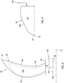
FIG. 5 is a partial sectional illustration of a portion of a guide vane with an internal passage. -
FIG. 6 is a partial sectional illustration of a portion of the guide vane with outlets from the internal passage to an external environment. -
FIG. 7 is a partial sectional schematic illustration of the propulsion system with an outlet from the anti-icing system directed into an exhaust section of a gas generator. -
FIG. 8 is a partial sectional schematic illustration of an open propulsor rotor serviced by the anti-icing system. -
FIG. 9 is a partial sectional schematic illustration of a nose cone serviced by the anti-icing system. -
FIG. 10 is a sectional schematic illustration of another propulsion system. -
FIG. 11 is a sectional schematic illustration of still another propulsion system. -
FIG. 1 is a side schematic illustration of apropulsion system 20 for an aircraft. The aircraft may be an airplane, a drone (e.g., an unmanned aerial vehicle (UAV)) or any other manned or unmanned aerial vehicle or system. Theaircraft propulsion system 20 may be configured as an open rotor propulsion system. Theaircraft propulsion system 20 ofFIG. 1 , for example, extends axially along anaxis 22 between a forward,upstream end 23 of theaircraft propulsion system 20 and an aft,downstream end 25 of theaircraft propulsion system 20. Theaxis 22 may be a centerline axis of theaircraft propulsion system 20 and/or one or more of its members. Theaxis 22 may also or alternatively be a rotational axis of one or more members of theaircraft propulsion system 20. Theaircraft propulsion system 20 ofFIG. 1 includes apropulsion module 24, a gas generator 26 (e.g., a reverse flow gas generator) and ananti-icing system 28 servicing thepropulsion module 24. - The
propulsion module 24 ofFIG. 1 includes anopen propulsor rotor 30 and an openguide vane structure 32. Here, the term "open" may describe a component which is open to an environment 33 (e.g., an ambient environment) external to theaircraft propulsion system 20 and itspropulsion module 24. Thepropulsion module members FIG. 1 , for example, are un-ducted and unshrouded components of theaircraft propulsion system 20 and itspropulsion module 24. Thepropulsion module 24 ofFIG. 1 also includes anose cone 34 disposed at (e.g., on, adjacent or proximate) the propulsion systemupstream end 23. Briefly, thisnose cone 34 may be configured as a spinner which is rotatable with thepropulsor rotor 30 about theaxis 22. Alternatively, thenose cone 34 may be configured as a stationary structure of thepropulsion module 24. - The
propulsor rotor 30 includes a rotor base 36 (e.g., a disk or a hub) and a plurality of open propulsor blades 38 (e.g., airfoils). Thepropulsor blades 38 are arranged circumferentially around therotor base 36 and theaxis 22 in an array. Each of thepropulsor blades 38 is connected to (e.g., formed integral with or otherwise attached to) therotor base 36. - Each
propulsor blade 38 projects spanwise along a span line of the respective propulsor blade 38 (e.g., radially relative to the axis 22) out from anexterior surface 40 of therotor base 36, into theexternal environment 33, to an unshrouded,distal tip 42 of therespective propulsor blade 38. Eachpropulsor blade 38 is thereby configured as an un-ducted and unshrouded propulsor blade which is exposed to (e.g., disposed in) the surroundingexternal environment 33. Referring toFIG. 2 , eachpropulsor blade 38 extends longitudinally along a mean line 44 (e.g., a camber line) of therespective propulsor blade 38 from a leadingedge 46 of therespective propulsor blade 38 to a trailingedge 48 of therespective propulsor blade 38. Eachpropulsor blade 38 extends laterally between and to opposing side exterior surfaces 50A and 50B (generally referred to as "50") of therespective propulsor blade 38. The firstblade exterior surface 50A may be a concave, pressure side surface of therespective propulsor blade 38. The secondblade exterior surface 50B may be a convex, suction side surface of therespective propulsor blade 38. Each of these blade exterior surfaces 50 extends longitudinally along the blade meanline 44 between and meet at the respectiveblade leading edge 46 and the respectiveblade trailing edge 48. Referring toFIG. 1 , eachblade element exterior surface 40 to therespective blade tip 42. - The
propulsor rotor 30 ofFIG. 1 is arranged axially along theaxis 22 between thenose cone 34 and theguide vane structure 32. Thepropulsor rotor 30 ofFIG. 1 , in particular, is arranged axially downstream of thenose cone 34 and axially upstream of theguide vane structure 32. A forward, upstream end of thepropulsor rotor 30 may be disposed axially next to (e.g., adjacent, slightly spaced from) an aft, downstream end of thenose cone 34. An aft, downstream end of thepropulsor rotor 30 may be disposed axially next to a forward, upstream end of theguide vane structure 32. - The
guide vane structure 32 includes aninner platform 52 and a plurality of open guide vanes 54 (e.g., airfoils). The guide vanes 54 are arranged circumferentially around theinner platform 52 and theaxis 22 in an array. Each of the guide vanes 54 is connected to theinner platform 52. - Each
guide vane 54 projects spanwise along a span line of the respective guide vane 54 (e.g., radially relative to the axis 22) out from anexterior surface 56 of theinner platform 52, into theexternal environment 33, to an unshrouded,distal tip 58 of therespective guide vane 54. Eachguide vane 54 is thereby configured as an un-ducted and unshrouded guide vane which is exposed to (e.g., disposed in) the surroundingexternal environment 33. Referring toFIG. 3 , eachguide vane 54 extends longitudinally along a mean line 59 (e.g., a camber line) of therespective guide vane 54 from a leadingedge 62 of therespective guide vane 54 to a trailingedge 64 of therespective guide vane 54. Eachguide vane 54 extends laterally between and to opposing side exterior surfaces 66A and 66B (generally referred to as "66") of therespective guide vane 54. The firstvane exterior surface 66A may be a convex, suction side surface of therespective guide vane 54. The secondvane exterior surface 66B may be a concave, pressure side surface of therespective guide vane 54. Each of these vane exterior surfaces 66 extends longitudinally along the vane meanline 59 between (and meet at) the respectivevane leading edge 62 and the respectivevane trailing edge 64. Referring toFIG. 1 , eachvane element platform exterior surface 56 to therespective vane tip 58. - In some embodiments, each of the
guide vanes 54 may be a fixed guide vane which is fixedly connected to theinner platform 52 and/or an internal support structure covered by theinner platform 52. In other embodiments, some or all of theguide vanes 54 may each be a variable guide vane which is pivotally connected to theinner platform 52 and/or an internal support structure covered by theinner platform 52. Some of all of theguide vanes 54, for example, may be configured to pivot about a pivot axis of therespective guide vane 54. - The
guide vane structure 32 ofFIG. 1 is arranged axially between thepropulsor rotor 30 and one or more sections (e.g., 68-72) of thegas generator 26, or an entirety of thegas generator 26. Theguide vane structure 32 ofFIG. 1 , in particular, is arranged axially downstream of thepropulsor rotor 30 and axially upstream of thegas generator 26 and its engine sections 68-72. An aft end of theguide vane structure 32 may be disposed axially next to a forward, upstream end of thegas generator 26; e.g., relative to fluid flow outside of thegas generator 26. - The
gas generator 26 ofFIG. 1 includes a reverse-flow core flowpath 74, aninlet section 68, acompressor section 69, acombustor section 70, aturbine section 71 and anexhaust section 72. Thecompressor section 69 ofFIG. 1 includes a low pressure compressor (LPC)section 69A and a high pressure compressor (HPC)section 69B. Theturbine section 71 includes a high pressure turbine (HPT)section 71A, an intermediate pressure turbine (IPT)section 71B and a power turbine (PT)section 71C, whichPT section 71C is a low pressure turbine (LPT) section of theaircraft propulsion system 20. Thecore flowpath 74 extends longitudinally in thegas generator 26 from anairflow inlet 76 into thecore flowpath 74 to a combustion products exhaust 78 from thecore flowpath 74. More particularly, thecore flowpath 74 extends sequentially through theinlet section 68, theLPC section 69A, theHPC section 69B, thecombustor section 70, theHPT section 71A, theIPT section 71B, thePT section 71C and theexhaust section 72 between theflowpath inlet 76 and theflowpath exhaust 78. Theflowpath inlet 76 may be configured as an airflow inlet into thegas generator 26 or, more generally, theaircraft propulsion system 20. Theflowpath exhaust 78 may be configured as a combustion products exhaust from thegas generator 26 or, more generally, theaircraft propulsion system 20. - The
engine sections 69A-71C may be arranged sequentially along theaxis 22 between propulsion systemdownstream end 25 and the propulsion systemupstream end 23. With this arrangement, eachengine section axis 22 between (A) thepropulsion module 24 and itscomponents combustor section 70. Theexhaust section 72 ofFIG. 1 is also arranged axially along theaxis 22 between (A) thepropulsion module 24 and itscomponents turbine section 71 and each of itssub-sections engine sections 69A-71C ofFIG. 1 are arranged within an engine housing; e.g., a case and a nacelle. Thepropulsor rotor 30 and theguide vane structure 32 are arranged outside of the engine housing. - Each of the
engine sections axis 22 in an array. The rotor blades may also be arranged into one or more stages longitudinally along thecore flowpath 74. Each of the rotor blades is connected to the respective rotor base. Each of the rotor blades projects radially (e.g., spanwise) out from the respective rotor base into thecore flowpath 74 and to an unshrouded, distal tip of the respective rotor blade. - The
HPC rotor 81 is coupled to and rotatable with theHPT rotor 82. TheHPC rotor 81 ofFIG. 1 , for example, is connected to theHPT rotor 82 by ahigh speed shaft 86. At least (or only) theHPC rotor 81, theHPT rotor 82 and thehigh speed shaft 86 collectively form a highspeed rotating assembly 88; e.g., a high speed spool of thegas generator 26. TheLPC rotor 80 is coupled to and rotatable with theIPT rotor 83. TheLPC rotor 80 ofFIG. 1 , for example, is connected to theIPT rotor 83 by alow speed shaft 90. At least (or only) theLPC rotor 80, theIPT rotor 83 and thelow speed shaft 90 collectively form a lowspeed rotating assembly 92; e.g., a low speed spool of thegas generator 26. The PT rotor 84 (e.g., the PT rotor) is connected to and rotatable with apower turbine shaft 94. At least (or only) thePT rotor 84 and thepower turbine shaft 94 collectively form a powerturbine rotating assembly 96. Thepropulsor rotor 30 is connected to and rotatable with apropulsor shaft 98. At least (or only) thepropulsor rotor 30 and thepropulsor shaft 98 collectively form apropulsor rotating assembly 100. Thispropulsor rotating assembly 100 is coupled to the powerturbine rotating assembly 96 through adrivetrain 102. Thedrivetrain 102 may be configured as a geared drivetrain, where a geartrain 104 (e.g., a transmission, a speed change device, an epicyclic geartrain, etc.) is disposed between and operatively couples thepropulsor rotating assembly 100 and itspropulsor shaft 98 to the powerturbine rotating assembly 96 and itspower turbine shaft 94. With this arrangement, thepropulsor rotor 30 may rotate at a different (e.g., slower) rotational velocity than the powerturbine rotating assembly 96 and itsPT rotor 84. However, thedrivetrain 102 may alternatively be configured as a direct drive drivetrain, where thegeartrain 104 is omitted. With this arrangement, thepropulsor rotor 30 and thePT rotor 84 may rotate at a common (the same) rotational velocity. Referring again toFIG. 1 , each of therotating assemblies axis 22. - During operation of the
aircraft propulsion system 20, ambient air within theexternal environment 33 is propelled by thepropulsor rotor 30 across theguide vane structure 32 in an aft, downstream direction towards the propulsion systemdownstream end 25. Theguide vane structure 32 and itsguide vanes 54 condition (e.g., straighten out) the air propelled by thepropulsor rotor 30, for example, to remove or reduce circumferential swirl. A major outer portion of the air propelled by thepropulsor rotor 30 across theguide vane structure 32 provides forward thrust. A minor inner portion of the air propelled by thepropulsor rotor 30 across theguide vane structure 32 is directed into thecore flowpath 74 by theinlet section 68 and itsflowpath inlet 76. This air entering thecore flowpath 74 may be referred to as "core air". - The core air is compressed by the
LPC rotor 80 and theHPC rotor 81 and directed into a combustion chamber 106 (e.g., an annular combustion chamber) of a combustor (e.g., an annular combustor) in thecombustor section 70. Fuel is injected into thecombustion chamber 106 and mixed with the compressed core air to provide a fuel-air mixture. This fuel-air mixture is ignited and combustion products thereof flow through and sequentially drive rotation of theHPT rotor 82, theIPT rotor 83 and thePT rotor 84. The rotation of theHPT rotor 82 and theIPT rotor 83 respectively drive rotation of theHPC rotor 81 and theLPC rotor 80 and, thus, compression of the air received from theflowpath inlet 76. The rotation of the PT rotor 84 (e.g., the LPT rotor) drives rotation of thepropulsor rotor 30 through thedrivetrain 102. The rotation of thepropulsor rotor 30, in turn, propels the ambient air within theexternal environment 33 across theguide vane structure 32 in the aft, downstream direction. With this arrangement, thegas generator 26 powers operation of (e.g., drives rotation of) thepropulsor rotor 30 during aircraft propulsion system operation. - Referring to
FIG. 4 , theanti-icing system 28 is configured to heat one or more exterior surfaces of thepropulsion module 24, where each exterior surface is exposed to the ambient air within theexterior environment 33. By heating those exterior surfaces, theanti-icing system 28 may reduce or prevent ice accumulation on the heated exterior surfaces when, for example, theaircraft propulsion system 20 is operating in cold and damp environments. For ease of description, the heated exterior surfaces are generally described below as the exterior surfaces 66A, 66B of the guide vanes 54. However, as described below in further detail, it is contemplated theanti-icing system 28 may also or alternatively heat the exterior surfaces 50A, 50B of thepropulsor blades 38, anexterior surface 108 of thenose cone 34 and/or one or more other exterior surfaces of thepropulsion module 24. - The
anti-icing system 28 ofFIG. 4 includes agas flow circuit 110 and a bleed port 112 (or multiple bleed ports). Theanti-icing system 28 may also include (or omit) a mixingvalve 114 and acool air passage 116. - The
bleed port 112 ofFIG. 4 is disposed in theexhaust section 72 along thecore flowpath 74. Thisbleed port 112 is configured to bleed gas - the combustion products - flowing through thecore flowpath 74 within theexhaust section 72, and direct that bleed gas into thegas flow circuit 110. Thebleed port 112 may be configured as or otherwise include an opening in anouter flowpath wall 118 of theexhaust section 72, whichouter flowpath wall 118 forms an outer peripheral boundary of thecore flowpath 74 within theexhaust section 72. Alternatively, thebleed port 112 may be configured as or otherwise include a scoop along theouter flowpath wall 118. - The
gas flow circuit 110 is configured to direct heated gas to thepropulsion module 24, where the heated gas is or otherwise includes the gas bled from thecore flowpath 74 by thebleed port 112. Thegas flow circuit 110 ofFIG. 4 , in particular, is configured to direct the bleed gas from thebleed port 112 into theguide vane structure 32 and itsguide vanes 54. Thegas flow circuit 110 ofFIG. 4 , for example, includes a manifold 120 and a plurality ofinternal passages 122. The manifold 120 fluidly couples the bleed port 112 (or bleed ports) to thepassages 122. Each of thepassages 122 is thereby fluidly coupled to the bleed port 112 (or bleed ports) through themanifold 120. Each of thesepassages 122 extends into a respective one of the guide vanes 54. Referring toFIG. 5 , eachpassage 122 also extends along and in close proximity to theexternal surfaces respective guide vane 54 to be heated. For example, within eachguide vane 54, an external skin of theguide vane 54 forming the respective exterior surface(s) 66 may also form a peripheral boundary of therespective passage 122. The heated gas flowing within thepassage 122 may thereby heat the external skin and, thus, the respective exterior surface(s) 66 of therespective guide vane 54. - Referring to
FIG. 4 , the mixingvalve 114 is disposed fluidly between thecool air passage 116 to thegas flow circuit 110. Thiscool air passage 116 may be configured to direct relatively cool air (e.g., the ambient air) from the external environment 33 (or another cool air source) to the mixingvalve 114. The mixingvalve 114 is configured to facilitate selective mixing of at least some of the cool air from thecool air passage 116 with the bleed gas within thegas flow circuit 110. For example, where a temperature of the bleed gas is equal to or above a threshold, the mixingvalve 114 may facilitate the mixing of the bleed gas with the cool air to reduce a temperature of the heated gas - here, a mixture of the bleed gas and the cool air - provided to the guide vanes 54. However, where the temperature of the bleed gas is below the threshold, the mixingvalve 114 may close and the heated gas provided to theguide vanes 54 may be (e.g., solely) the bleed gas. - With a reverser flow gas generator arrangement, the
anti-icing system 28 ofFIG. 4 (see alsoFIG. 1 ) may readily utilize the combustion products within theexhaust section 72 to supply the heated gas for heating the exterior surfaces 66 of the guide vanes 54. Moreover, with theexhaust section 72 arranged between the engine sections 68-71C (seeFIG. 1 ) and thepropulsion module 24, the bleed gas may be routed by thegas flow circuit 110 to thepropulsion module 24 without passing in close proximity to fuel lines servicing thecombustor section 70 and/or without passing through a firewall. - In some embodiments, referring to
FIG. 6 , eachpassage 122 may extend to or otherwise be fluidly coupled with one ormore outlets 124 in the respective propulsion module component (e.g., respective guide vane 54) being heated. Theoutlets 124 ofFIG. 6 , for example, are disposed in one or more of the exterior surfaces 66 being heated by the heated gas. In other embodiments, referring toFIG. 7 , thegas flow circuit 110 and itspassages 122 may be fluidly coupled with an outlet 126 (or multiple outlets) along thecore flowpath 74. Theoutlet 126 ofFIG. 7 , for example, is disposed along thecore flowpath 74 in theexhaust section 72, for example downstream of thebleed port 112. With this arrangement, theanti-icing system 28 and itsgas flow circuit 110 may exhaust the heated gas back into thecore flowpath 74 after using that heated gas to heat the respective exterior surfaces 66. - Referring to
FIG. 4 , the exterior surfaces heated by theanti-icing system 28 are described above as being the vanes exterior surfaces 66. However, as discussed above, theanti-icing system 28 may also or alternatively heat one or more other exterior surfaces of thepropulsion module 24. For example, referring toFIG. 8 , one ormore passages 122 of theanti-icing system 28 may also or alternatively extend into thepropulsor rotor 30. Eachpassage 122 ofFIG. 8 , for example, may extend into a respective one of thepropulsor blades 38 to facilitate heating of one or more of its blade exterior surfaces 50 with the heated gas. In another example, referring toFIG. 9 , a passage 122 (or cavity) of theanti-icing system 28 may also or alternatively extend into thenose cone 34 to facilitate heating of the nose coneexterior surface 108 with the heated gas. Theanti-icing system 28 of the present invention, however, is not limited to heating the foregoing exemplary exterior surfaces. - In some embodiments, referring to
FIG. 1 , thegas generator 26 and itsrotating assemblies propulsion module 24 and itspropulsor rotating assembly 100. In other embodiments, referring toFIGS. 10 and11 , one or morerotating assemblies gas generator 26 may rotate about anaxis 128 which is offset from the rotational axis - the axis 22 - of thepropulsor rotating assembly 100. Thegas generator axis 128 ofFIG. 10 , for example, is angularly offset from thepropulsor axis 22 by an includedangle 130. Thisangle 130 is a non-zero acute angle less than, for example, thirty or forty-five degrees (30-45°); e.g., between one degree (1°) and five degrees (5°), between five degrees (5°) and ten degrees (10°), between ten degrees (10°) and twenty degrees (20°), etc. Here, thegas generator axis 128 is coincident with thepropulsor axis 22; however, the present invention is not limited to such an exemplary arrangement. In another example, referring toFIG. 11 , the gas generator axis 128 (and the power turbine axis) are laterally offset (e.g., spaced from) thepropulsor axis 22. Theaxis 128, however, may be parallel with thepropulsor axis 22. - The
aircraft propulsion system 20 may include various gas generator configurations other than the ones described above. For example, while thegas generator 26 is described above with twocore rotating assemblies gas generator 26 may alternatively be configured with a single core rotating assembly (e.g., 88 or 92) or three or more core rotating assemblies. Moreover, while thePT rotor 84 is described above as a free turbine rotor, it is contemplated thePT rotor 84 may alternatively be coupled to one of the corerotating assemblies - The
aircraft propulsion system 20 is described above with a tractor configuration; e.g., where thepropulsor rotor 30 is disposed at or otherwise near the propulsion systemupstream end 23. It is contemplated, however, theaircraft propulsion system 20 may be reversed to provide a pusher fan configuration. The present invention therefore is not limited to any particular open rotor propulsion system arrangement. - While various embodiments of the present invention have been described, it will be apparent to those of ordinary skill in the art that many more embodiments and implementations are possible within the scope of the invention. For example, the present invention as described herein includes several aspects and embodiments that include particular features. Although these features may be described individually, it is within the scope of the present invention that some or all of these features may be combined with any one of the aspects and remain within the scope of the invention. Accordingly, the present invention is not to be restricted except in light of the attached claims and their equivalents.
Claims (15)
- An assembly for an aircraft propulsion system (20), the assembly comprising:a propulsion module (24) comprising an open propulsor rotor (30);a gas generator (26) configured to drive rotation of the open propulsor rotor (30) about an axis (22), the gas generator (26) including a flowpath (74), a compressor section (69), a combustor section (70), a turbine section (71) and an exhaust section (72), the flowpath (74) extending through the compressor section (69), the combustor section (70), the turbine section (71) and the exhaust section (72) from an inlet (76) into the flowpath (74) to an exhaust (78) from the flowpath (74), wherein the turbine section (71) is axially between the combustor section (70) and the open propulsor rotor (30) along the axis (22); andan anti-icing system (28) configured to bleed gas from the flowpath (74) in the exhaust section (72) to provide heated gas, and configured to direct the heated gas to the propulsion module (24) to reduce or prevent ice accumulation on an exterior surface (50, 66, 108) of the propulsion module (24).
- The assembly of claim 1, wherein:the propulsion module (24) further comprises a plurality of open guide vanes (54) arranged circumferentially about the axis (22);the plurality of open guide vanes (54) include a first open guide vane (54); andthe first open guide vane (54) comprises the exterior surface (50, 66, 108).
- The assembly of claim 2, wherein:the anti-icing system (28) includes a bleed port (112) and a passage (122);the bleed port (112) is fluidly coupled to the passage (122) and disposed in the exhaust section (72) along the flowpath (74); andthe passage (122) extends into the first open guide vane (54).
- The assembly of claim 3, wherein:the anti-icing system (28) further includes an outlet (124);the outlet (124) is disposed in the exterior surface (50, 66, 108); andthe passage (122) fluidly couples the bleed port (112) to the outlet (124).
- The assembly of claim 3, wherein:the anti-icing system (28) further includes an outlet (126);the outlet (126) is disposed in the exhaust section (72) downstream of the bleed port (112) along the flowpath (74); andthe passage (122) fluidly couples the bleed port (112) to the outlet (126).
- The assembly of any of claims 2 to 5, wherein the turbine section (71) is axially between the combustor section (70) and the plurality of open guide vanes (54) along the axis (22).
- The assembly of any preceding claim, wherein:the open propulsor rotor (30) comprises the exterior surface (50, 66, 108); and/orthe propulsion module (24) further comprises a nose cone (34) and the nose cone (34) comprises the exterior surface (50, 66, 108).
- The assembly of any preceding claim, wherein:the anti-icing system (28) includes a mixing valve (114) configured to mix ambient air with the gas bled from the flowpath (74) in the exhaust section (72) to provide the heated gas; orthe heated gas consists of the gas bled from the flowpath (74) in the exhaust section (72).
- The assembly of any preceding claim, wherein:the turbine section (71) comprises a free power turbine rotor (84), and the free power turbine rotor (84) is coupled to and configured to drive the rotation of the open propulsor rotor (30); and, optionallythe assembly further comprises a geartrain (104) coupling the free power turbine rotor (84) to the open propulsor rotor (30).
- The assembly of claim 9, wherein:the free power turbine rotor (84) is rotatable about the axis (22); orthe axis (22) is a first axis, and the free power turbine rotor (84) is rotatable about a second axis (128) that is offset from the first axis (22).
- The assembly of any of claims 1 to 9, wherein:the gas generator (26) comprises a rotating assembly rotatable about the axis (22); andthe rotating assembly (88, 92) includes a compressor rotor, a turbine rotor and a shaft coupling the turbine rotor to the compressor rotor, the compressor rotor is in the compressor section (69), and the turbine rotor is in the turbine section (71).
- The assembly of any of claims 1 to 10, wherein:the axis (22) is a first axis (22), and the gas generator (26) comprises a rotating assembly rotatable about a second axis (128) offset from the first axis (22); andthe rotating assembly (88, 92) includes a compressor rotor, a turbine rotor and a shaft coupling the turbine rotor to the compressor rotor, the compressor rotor is in the compressor section (69), and the turbine rotor is in the turbine section (71).
- An assembly for an aircraft propulsion system (20), comprising:a propulsor rotor (30) rotatable about an axis (22);a guide vane structure (32) including a plurality of guide vanes (54) arranged circumferentially about the axis (22), the guide vane structure (32) axially next to the propulsor rotor (30);a gas generator (26) configured to drive rotation of the propulsor rotor (30) about the axis (22), the gas generator (26) including a flowpath (74), a compressor section (69), a combustor section (70), a turbine section (71) and an exhaust section (72), the flowpath (74) extending through the compressor section (69), the combustor section (70), the turbine section (71) and the exhaust section (72) from an inlet (76) into the flowpath (74) to an exhaust (78) from the flowpath (74); andan anti-icing system (28) configured to bleed combustion products from the flowpath (74) in the exhaust section (72) to provide heated gas, and the anti-icing system (28) configured to direct the heated gas to the guide vane structure (32) to reduce or prevent ice accumulation on the plurality of guide vanes (54).
- The assembly of claim 13, wherein:the propulsor rotor (30) comprises an un-ducted propulsor rotor, and the guide vane structure (32) comprises an un-ducted guide vane structure; and/orthe guide vane structure (32) is downstream of the propulsor rotor (30).
- An assembly for an aircraft propulsion system (20), comprising:a propulsion module (24) comprising an open propulsor rotor (30) rotatable about an axis (22);a gas generator (26) configured to power operation of the open propulsor rotor (30), the gas generator (26) including a flowpath (74), a compressor section (69), a combustor section (70), a turbine section (71) and an exhaust section (72), the flowpath (74) extending through the compressor section (69), the combustor section (70), the turbine section (71) and the exhaust section (72) from an inlet into the flowpath (74) to an exhaust from the flowpath (74); andan anti-icing system (28) including a bleed port (112) and a passage (122), the bleed port (112) fluidly coupled to the passage (122) and disposed in the exhaust section (72) along the flowpath (74), and the passage (122) extending into the propulsion module (24).
Applications Claiming Priority (1)
| Application Number | Priority Date | Filing Date | Title |
|---|---|---|---|
| US18/538,300 US20250197013A1 (en) | 2023-12-13 | 2023-12-13 | Open rotor aircraft propulsion system with anti-icing system |
Publications (2)
| Publication Number | Publication Date |
|---|---|
| EP4570650A2 true EP4570650A2 (en) | 2025-06-18 |
| EP4570650A3 EP4570650A3 (en) | 2025-08-13 |
Family
ID=93924045
Family Applications (1)
| Application Number | Title | Priority Date | Filing Date |
|---|---|---|---|
| EP24219926.3A Pending EP4570650A3 (en) | 2023-12-13 | 2024-12-13 | Open rotor aircraft propulsion system with anti-icing system |
Country Status (2)
| Country | Link |
|---|---|
| US (1) | US20250197013A1 (en) |
| EP (1) | EP4570650A3 (en) |
Family Cites Families (12)
| Publication number | Priority date | Publication date | Assignee | Title |
|---|---|---|---|---|
| US2507044A (en) * | 1943-09-20 | 1950-05-09 | Curtiss Wright Corp | Deicing system for aircraft |
| US20090108134A1 (en) * | 2007-10-25 | 2009-04-30 | General Electric Company | Icing protection system and method for enhancing heat transfer |
| FR2945270B1 (en) * | 2009-05-05 | 2011-04-22 | Airbus France | DEFROSTING DEVICE FOR PROPFAN PROPELLER BLADES |
| GB201009264D0 (en) * | 2010-06-03 | 2010-07-21 | Rolls Royce Plc | Heat transfer arrangement for fluid washed surfaces |
| FR2967646B1 (en) * | 2010-11-19 | 2015-03-06 | Snecma | BLADE FOR A TURBOMACHINE PROPELLER |
| US10202941B2 (en) * | 2012-11-12 | 2019-02-12 | United Technologies Corporation | Reverse core turbine engine mounted above aircraft wing |
| FR3050763B1 (en) * | 2016-04-28 | 2018-04-13 | Safran Aircraft Engines | AIR CIRCULATION DEVICE FOR A TURBOMACHINE COMPRISING A HOT AIR DERIVATION SYSTEM TO A HEAT EXCHANGER |
| US10968827B2 (en) * | 2016-09-28 | 2021-04-06 | Pratt & Whitney Canada Corp. | Anti-icing apparatus for a nose cone of a gas turbine engine |
| US20210107676A1 (en) * | 2019-10-11 | 2021-04-15 | General Electric Company | Aircraft Having an Aft Engine and Auxiliary Power Unit |
| US20210108572A1 (en) * | 2019-10-15 | 2021-04-15 | General Electric Company | Advance ratio for single unducted rotor engine |
| FR3112809B1 (en) * | 2020-07-23 | 2022-07-29 | Safran Aircraft Engines | TURBOMACHINE MODULE EQUIPPED WITH A PROPELLER AND STATOR VANE SUPPORTED BY HOLDING MEANS AND CORRESPONDING TURBOMACHINE |
| US12065989B2 (en) * | 2022-04-11 | 2024-08-20 | General Electric Company | Gas turbine engine with third stream |
-
2023
- 2023-12-13 US US18/538,300 patent/US20250197013A1/en active Pending
-
2024
- 2024-12-13 EP EP24219926.3A patent/EP4570650A3/en active Pending
Also Published As
| Publication number | Publication date |
|---|---|
| EP4570650A3 (en) | 2025-08-13 |
| US20250197013A1 (en) | 2025-06-19 |
Similar Documents
| Publication | Publication Date | Title |
|---|---|---|
| US7216475B2 (en) | Aft FLADE engine | |
| US7134271B2 (en) | Thrust vectoring aft FLADE engine | |
| US20260078682A1 (en) | Gas turbine engine | |
| EP4464881A1 (en) | Pressure control for bifurcated flow of a turbine engine | |
| EP4653321A2 (en) | Open rotor aircraft propulsion system with bypass flowpath | |
| EP4589130A2 (en) | Regulating core air bled from a turbine engine core flowpath | |
| EP4509703A1 (en) | Aircraft powerplant with electric powertrain | |
| EP4385899A1 (en) | Aircraft thermal anti-icing system | |
| EP4570650A2 (en) | Open rotor aircraft propulsion system with anti-icing system | |
| EP4411116A1 (en) | Buffer air system for a bearing compartment of a gas turbine | |
| US12397924B2 (en) | Open rotor aircraft propulsion system with bypass flowpath | |
| EP4733566A2 (en) | Thermal management system for open rotor aircraft propulsion system | |
| US12410712B1 (en) | Rotor blade with apertured cooling air deflector | |
| US20260092556A1 (en) | Open rotor propulsion system with forward exhaust outlet(s) | |
| US12497895B1 (en) | Air cooling system for stator vane structure outer platform | |
| US12454911B2 (en) | Bleeding core air from a turbine engine core flowpath | |
| US20260091873A1 (en) | Open rotor propulsion system with exhaust mixer(s) | |
| US20260092530A1 (en) | Turbine Engine Rotor Blade With Contoured Pocket Surface(S) | |
| US20260062137A1 (en) | Thermal management system for open rotor aircraft propulsion system | |
| US20260009334A1 (en) | Notched turbine vane baffle | |
| US20250198328A1 (en) | Ventilation system for aircraft propulsion system | |
| US20260098547A1 (en) | Lift fan assembly for an aircraft | |
| US20250027423A1 (en) | Turbine engine tip clearance control system with thrust bearing | |
| CN117588275A (en) | gas turbine engine |
Legal Events
| Date | Code | Title | Description |
|---|---|---|---|
| PUAI | Public reference made under article 153(3) epc to a published international application that has entered the european phase |
Free format text: ORIGINAL CODE: 0009012 |
|
| STAA | Information on the status of an ep patent application or granted ep patent |
Free format text: STATUS: THE APPLICATION HAS BEEN PUBLISHED |
|
| AK | Designated contracting states |
Kind code of ref document: A2 Designated state(s): AL AT BE BG CH CY CZ DE DK EE ES FI FR GB GR HR HU IE IS IT LI LT LU LV MC ME MK MT NL NO PL PT RO RS SE SI SK SM TR |
|
| PUAL | Search report despatched |
Free format text: ORIGINAL CODE: 0009013 |
|
| AK | Designated contracting states |
Kind code of ref document: A3 Designated state(s): AL AT BE BG CH CY CZ DE DK EE ES FI FR GB GR HR HU IE IS IT LI LT LU LV MC ME MK MT NL NO PL PT RO RS SE SI SK SM TR |
|
| RIC1 | Information provided on ipc code assigned before grant |
Ipc: B64C 11/24 20060101AFI20250708BHEP Ipc: B64D 15/04 20060101ALI20250708BHEP Ipc: F01D 5/08 20060101ALI20250708BHEP Ipc: F01D 5/18 20060101ALI20250708BHEP |
|
| STAA | Information on the status of an ep patent application or granted ep patent |
Free format text: STATUS: REQUEST FOR EXAMINATION WAS MADE |
|
| 17P | Request for examination filed |
Effective date: 20260213 |