EP4570637A1 - Vehicle control device and vehicle control system - Google Patents
Vehicle control device and vehicle control system Download PDFInfo
- Publication number
- EP4570637A1 EP4570637A1 EP23939680.7A EP23939680A EP4570637A1 EP 4570637 A1 EP4570637 A1 EP 4570637A1 EP 23939680 A EP23939680 A EP 23939680A EP 4570637 A1 EP4570637 A1 EP 4570637A1
- Authority
- EP
- European Patent Office
- Prior art keywords
- vehicle
- damping force
- notification
- vehicle control
- control device
- Prior art date
- Legal status (The legal status is an assumption and is not a legal conclusion. Google has not performed a legal analysis and makes no representation as to the accuracy of the status listed.)
- Pending
Links
Images

Classifications
-
- B—PERFORMING OPERATIONS; TRANSPORTING
- B62—LAND VEHICLES FOR TRAVELLING OTHERWISE THAN ON RAILS
- B62J—CYCLE SADDLES OR SEATS; AUXILIARY DEVICES OR ACCESSORIES SPECIALLY ADAPTED TO CYCLES AND NOT OTHERWISE PROVIDED FOR, e.g. ARTICLE CARRIERS OR CYCLE PROTECTORS
- B62J50/00—Arrangements specially adapted for use on cycles not provided for in main groups B62J1/00 - B62J45/00
- B62J50/20—Information-providing devices
- B62J50/21—Information-providing devices intended to provide information to rider or passenger
-
- B—PERFORMING OPERATIONS; TRANSPORTING
- B60—VEHICLES IN GENERAL
- B60G—VEHICLE SUSPENSION ARRANGEMENTS
- B60G17/00—Resilient suspensions having means for adjusting the spring or vibration-damper characteristics, for regulating the distance between a supporting surface and a sprung part of vehicle or for locking suspension during use to meet varying vehicular or surface conditions, e.g. due to speed or load
- B60G17/015—Resilient suspensions having means for adjusting the spring or vibration-damper characteristics, for regulating the distance between a supporting surface and a sprung part of vehicle or for locking suspension during use to meet varying vehicular or surface conditions, e.g. due to speed or load the regulating means comprising electric or electronic elements
- B60G17/016—Resilient suspensions having means for adjusting the spring or vibration-damper characteristics, for regulating the distance between a supporting surface and a sprung part of vehicle or for locking suspension during use to meet varying vehicular or surface conditions, e.g. due to speed or load the regulating means comprising electric or electronic elements characterised by their responsiveness, when the vehicle is travelling, to specific motion, a specific condition, or driver input
- B60G17/0165—Resilient suspensions having means for adjusting the spring or vibration-damper characteristics, for regulating the distance between a supporting surface and a sprung part of vehicle or for locking suspension during use to meet varying vehicular or surface conditions, e.g. due to speed or load the regulating means comprising electric or electronic elements characterised by their responsiveness, when the vehicle is travelling, to specific motion, a specific condition, or driver input to an external condition, e.g. rough road surface, side wind
-
- B—PERFORMING OPERATIONS; TRANSPORTING
- B60—VEHICLES IN GENERAL
- B60G—VEHICLE SUSPENSION ARRANGEMENTS
- B60G17/00—Resilient suspensions having means for adjusting the spring or vibration-damper characteristics, for regulating the distance between a supporting surface and a sprung part of vehicle or for locking suspension during use to meet varying vehicular or surface conditions, e.g. due to speed or load
- B60G17/015—Resilient suspensions having means for adjusting the spring or vibration-damper characteristics, for regulating the distance between a supporting surface and a sprung part of vehicle or for locking suspension during use to meet varying vehicular or surface conditions, e.g. due to speed or load the regulating means comprising electric or electronic elements
- B60G17/0195—Resilient suspensions having means for adjusting the spring or vibration-damper characteristics, for regulating the distance between a supporting surface and a sprung part of vehicle or for locking suspension during use to meet varying vehicular or surface conditions, e.g. due to speed or load the regulating means comprising electric or electronic elements characterised by the regulation being combined with other vehicle control systems
-
- B—PERFORMING OPERATIONS; TRANSPORTING
- B60—VEHICLES IN GENERAL
- B60W—CONJOINT CONTROL OF VEHICLE SUB-UNITS OF DIFFERENT TYPE OR DIFFERENT FUNCTION; CONTROL SYSTEMS SPECIALLY ADAPTED FOR HYBRID VEHICLES; ROAD VEHICLE DRIVE CONTROL SYSTEMS FOR PURPOSES NOT RELATED TO THE CONTROL OF A PARTICULAR SUB-UNIT
- B60W10/00—Conjoint control of vehicle sub-units of different type or different function
- B60W10/22—Conjoint control of vehicle sub-units of different type or different function including control of suspension systems
-
- B—PERFORMING OPERATIONS; TRANSPORTING
- B60—VEHICLES IN GENERAL
- B60W—CONJOINT CONTROL OF VEHICLE SUB-UNITS OF DIFFERENT TYPE OR DIFFERENT FUNCTION; CONTROL SYSTEMS SPECIALLY ADAPTED FOR HYBRID VEHICLES; ROAD VEHICLE DRIVE CONTROL SYSTEMS FOR PURPOSES NOT RELATED TO THE CONTROL OF A PARTICULAR SUB-UNIT
- B60W50/00—Details of control systems for road vehicle drive control not related to the control of a particular sub-unit, e.g. process diagnostic or vehicle driver interfaces
- B60W50/08—Interaction between the driver and the control system
-
- B—PERFORMING OPERATIONS; TRANSPORTING
- B60—VEHICLES IN GENERAL
- B60W—CONJOINT CONTROL OF VEHICLE SUB-UNITS OF DIFFERENT TYPE OR DIFFERENT FUNCTION; CONTROL SYSTEMS SPECIALLY ADAPTED FOR HYBRID VEHICLES; ROAD VEHICLE DRIVE CONTROL SYSTEMS FOR PURPOSES NOT RELATED TO THE CONTROL OF A PARTICULAR SUB-UNIT
- B60W50/00—Details of control systems for road vehicle drive control not related to the control of a particular sub-unit, e.g. process diagnostic or vehicle driver interfaces
- B60W50/08—Interaction between the driver and the control system
- B60W50/14—Means for informing the driver, warning the driver or prompting a driver intervention
-
- B—PERFORMING OPERATIONS; TRANSPORTING
- B60—VEHICLES IN GENERAL
- B60W—CONJOINT CONTROL OF VEHICLE SUB-UNITS OF DIFFERENT TYPE OR DIFFERENT FUNCTION; CONTROL SYSTEMS SPECIALLY ADAPTED FOR HYBRID VEHICLES; ROAD VEHICLE DRIVE CONTROL SYSTEMS FOR PURPOSES NOT RELATED TO THE CONTROL OF A PARTICULAR SUB-UNIT
- B60W50/00—Details of control systems for road vehicle drive control not related to the control of a particular sub-unit, e.g. process diagnostic or vehicle driver interfaces
- B60W50/08—Interaction between the driver and the control system
- B60W50/14—Means for informing the driver, warning the driver or prompting a driver intervention
- B60W50/16—Tactile feedback to the driver, e.g. vibration or force feedback to the driver on the steering wheel or the accelerator pedal
-
- B—PERFORMING OPERATIONS; TRANSPORTING
- B62—LAND VEHICLES FOR TRAVELLING OTHERWISE THAN ON RAILS
- B62J—CYCLE SADDLES OR SEATS; AUXILIARY DEVICES OR ACCESSORIES SPECIALLY ADAPTED TO CYCLES AND NOT OTHERWISE PROVIDED FOR, e.g. ARTICLE CARRIERS OR CYCLE PROTECTORS
- B62J27/00—Safety equipment
-
- B—PERFORMING OPERATIONS; TRANSPORTING
- B60—VEHICLES IN GENERAL
- B60G—VEHICLE SUSPENSION ARRANGEMENTS
- B60G2300/00—Indexing codes relating to the type of vehicle
- B60G2300/12—Cycles; Motorcycles
-
- B—PERFORMING OPERATIONS; TRANSPORTING
- B60—VEHICLES IN GENERAL
- B60G—VEHICLE SUSPENSION ARRANGEMENTS
- B60G2400/00—Indexing codes relating to detected, measured or calculated conditions or factors
- B60G2400/80—Exterior conditions
- B60G2400/82—Ground surface
- B60G2400/823—Obstacle sensing
-
- B—PERFORMING OPERATIONS; TRANSPORTING
- B60—VEHICLES IN GENERAL
- B60G—VEHICLE SUSPENSION ARRANGEMENTS
- B60G2500/00—Indexing codes relating to the regulated action or device
- B60G2500/10—Damping action or damper
-
- B—PERFORMING OPERATIONS; TRANSPORTING
- B60—VEHICLES IN GENERAL
- B60G—VEHICLE SUSPENSION ARRANGEMENTS
- B60G2600/00—Indexing codes relating to particular elements, systems or processes used on suspension systems or suspension control systems
- B60G2600/04—Means for informing, instructing or displaying
- B60G2600/044—Alarm means
-
- B—PERFORMING OPERATIONS; TRANSPORTING
- B60—VEHICLES IN GENERAL
- B60W—CONJOINT CONTROL OF VEHICLE SUB-UNITS OF DIFFERENT TYPE OR DIFFERENT FUNCTION; CONTROL SYSTEMS SPECIALLY ADAPTED FOR HYBRID VEHICLES; ROAD VEHICLE DRIVE CONTROL SYSTEMS FOR PURPOSES NOT RELATED TO THE CONTROL OF A PARTICULAR SUB-UNIT
- B60W50/00—Details of control systems for road vehicle drive control not related to the control of a particular sub-unit, e.g. process diagnostic or vehicle driver interfaces
- B60W50/08—Interaction between the driver and the control system
- B60W50/14—Means for informing the driver, warning the driver or prompting a driver intervention
- B60W2050/143—Alarm means
-
- B—PERFORMING OPERATIONS; TRANSPORTING
- B60—VEHICLES IN GENERAL
- B60W—CONJOINT CONTROL OF VEHICLE SUB-UNITS OF DIFFERENT TYPE OR DIFFERENT FUNCTION; CONTROL SYSTEMS SPECIALLY ADAPTED FOR HYBRID VEHICLES; ROAD VEHICLE DRIVE CONTROL SYSTEMS FOR PURPOSES NOT RELATED TO THE CONTROL OF A PARTICULAR SUB-UNIT
- B60W50/00—Details of control systems for road vehicle drive control not related to the control of a particular sub-unit, e.g. process diagnostic or vehicle driver interfaces
- B60W50/08—Interaction between the driver and the control system
- B60W50/14—Means for informing the driver, warning the driver or prompting a driver intervention
- B60W2050/146—Display means
-
- B—PERFORMING OPERATIONS; TRANSPORTING
- B60—VEHICLES IN GENERAL
- B60W—CONJOINT CONTROL OF VEHICLE SUB-UNITS OF DIFFERENT TYPE OR DIFFERENT FUNCTION; CONTROL SYSTEMS SPECIALLY ADAPTED FOR HYBRID VEHICLES; ROAD VEHICLE DRIVE CONTROL SYSTEMS FOR PURPOSES NOT RELATED TO THE CONTROL OF A PARTICULAR SUB-UNIT
- B60W2720/00—Output or target parameters relating to overall vehicle dynamics
- B60W2720/16—Pitch
-
- B—PERFORMING OPERATIONS; TRANSPORTING
- B62—LAND VEHICLES FOR TRAVELLING OTHERWISE THAN ON RAILS
- B62K—CYCLES; CYCLE FRAMES; CYCLE STEERING DEVICES; RIDER-OPERATED TERMINAL CONTROLS SPECIALLY ADAPTED FOR CYCLES; CYCLE AXLE SUSPENSIONS; CYCLE SIDECARS, FORECARS, OR THE LIKE
- B62K25/00—Axle suspensions
- B62K25/04—Axle suspensions for mounting axles resiliently on cycle frame or fork
- B62K2025/044—Suspensions with automatic adjustment
Definitions
- the present invention relates to a vehicle control device that causes a damping device that damps a vibration of a vehicle to have a notification function by controlling a damping force of the damping device, and a vehicle control system including the vehicle control device and the damping device.
- Patent Literature 1 discloses a damper warning device that reduces a damping force of an electronically controlled steering damper to issue a warning. By lowering the damping force, a driver is given an artificial impression that a grip on a road surface decreases. In addition to the decrease in the damping force, it is preferable to further include a vibration warning device that performs a warning by causing a plurality of vibrators to vibrate. Each of the vibrators is a dedicated vibrator or an ABS modulator.
- Patent Literature 1 JP6424390B (claims 1, 2, and 4 and paragraphs 0006, 0029, 0030, and 0031)
- the notification function may not be sufficient only by decreasing the damping force (a vibrator may also be required).
- a vibrator may also be required.
- the rider may not be able to fully feel a vibration of the vibrator.
- An object of the present invention is to provide a vehicle control device capable of improving a notification function (physical sensation). Another object of the present invention will become apparent to a person skilled in the art by referring to an aspect and a preferred embodiment described below and the accompanying drawings.
- a vehicle control device includes:
- a vibration-like sensation can be transmitted to a driver of the vehicle, thereby improving the notification function of the damping device.
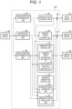
- FIG. 1 is a schematic configuration diagram of a vehicle control device and a vehicle control system.
- a vehicle control device 100 includes a damping force control unit 70 that controls a damping force of a damping device 80 that damps a vibration of a vehicle, and the vehicle control system may include, for example, the vehicle control device 100 and the damping device 80.
- the vehicle control system may further include other devices, for example, a sensor device 40, and the vehicle control device 100 may further include other units, for example, a notification determination unit 90.
- ECU electronice control unit
- the vehicle control device 100 or the damping force control unit 70 includes a damping force setting unit 71 that sets the damping force (predetermined damping force), and a notification function addition unit 72 that changes the damping force (predetermined damping force) set by the damping force setting unit 71, and typically adds a notification function (typically a change sensation function or a vibration function) to the damping device 80 by periodically changing the damping force in a rectangular wave form based on a predetermined damping force.
- the vehicle control device 100 or the vehicle control system can notify the driver of the vehicle using the damping device 80 mounted on the vehicle in the related art.
- the damping device 80 constitutes a suspension together with a suspension spring, the damping device 80 has a function of preventing a vibration of the suspension spring, and for example, a hydraulic type can be adopted.
- the hydraulic damping device 80 includes a variable damping force mechanism including an electric actuator (for example, a solenoid valve) capable of changing a degree of limitation of a flow rate of a flow passage through which oil passes.
- the damping force control unit 70 can determine a control current (damping force control amount) of the solenoid valve and output the control current to the damping device 80.
- the method for controlling the damping force of the damping device 80 is well known, and thus a description thereof is omitted in this specification.
- the damping force setting unit 71 may set or fix the damping force (predetermined damping force) according to a set value of hard setting, soft setting, or the like, or may set or change a damping force (predetermined damping force) to be a basis in accordance with a vehicle state such as a speed of the vehicle, a motion (movement) of the vehicle, or the like.
- the vehicle control device 100 can input a signal from the sensor device 40.
- the sensor device 40 includes at least one sensor, and typically has a plurality of sensors, and sensor values detected by the sensors are input to the vehicle control device 100.
- the vehicle control device 100 preferably further includes the notification determination unit 90 that determines whether to execute a notification to the driver based on the signal from the sensor device 40.
- a type of notification may be any type, and is not limited to this.
- the notification determination unit 90 may adopt a notification related to an advanced driver-assistance systems (ADAS).
- ADAS advanced driver-assistance systems
- the notification determination unit 90 determines a degree of proximity between the vehicle and an obstacle around the vehicle in order to achieve safety of the driver, and determines to execute the notification to the driver when the degree of proximity is equal to or greater than a predetermined value.
- the sensor device 40 for example, a camera acquires an image for sensing a condition around the vehicle, and the notification determination unit 90 can analyze the image to determine the proximity to the obstacle.
- the notification determination unit 90 can output a signal at a timing when the execution of the notification to the driver is necessary.
- the damping force control unit 70 or the notification function addition unit 72 can change the damping force (predetermined damping force) set by the damping force setting unit 71 based on the signal from the notification determination unit 90, and add the notification function to the damping device 80.
- the vehicle control device 100 preferably further includes a behavior generation control unit 55 that generates a forcible behavior in the vehicle.
- the behavior generation control unit 55 changes a speed of the vehicle. As the speed of the vehicle changes, movement occurs in the vehicle, that is, in the suspension, and while the damping force of the damping device 80 changes, a change in the damping force is easily felt in response to the movement of the vehicle or suspension. In other words, when the vehicle is traveling steadily at a constant speed, there is little movement in the suspension, but by generating the forcible behavior in the vehicle, the driver can reliably feel an increase or a decrease in the damping force.
- FIG. 2 are diagrams of respectively illustrating a timing at which a forcible behavior is generated in the vehicle and a timing at which the damping force set by the damping force setting unit 71 is changed
- (C) of FIG. 2 is a diagram of illustrating a notification function that is caused by the forcible behavior, specifically, forcible pitching and the change in the damping force.
- the notification function addition unit 72 increases or decreases the damping force based on the damping force (predetermined damping force) set by the damping force setting unit 71. Specifically, as illustrated in (B) of FIG. 2 , the notification function addition unit 72 periodically changes or increases or decreases the damping force based on the damping force (predetermined damping force), and changes the damping force, for example, in a rectangular wave form.
- the behavior generation control unit 55 or a braking force application unit 57 can turn on operation of the braking device 62. As illustrated in (A) of FIG. 2 , at a timing when the damping force changes, the behavior generation control unit 55 can cause, for example, the braking force application unit 57 to output a braking force application amount (predetermined amount) to the braking device 62 so as to automatically reduce the speed of the vehicle for only a first predetermined period.
- a braking force application amount predetermined amount
- the behavior generation control unit 55 can cause, for example, the braking force application unit 57 to output the braking force application amount (zero) to the braking device 62 so as to stop the reduction of the speed of the vehicle for only a second predetermined period immediately after the first predetermined period elapses.
- the behavior generation control unit 55 can cause, for example, the braking force application unit 57 to output the braking force application amount (predetermined amount) to the braking device 62 so as to resume the reduction of the speed of the vehicle for only a third predetermined period immediately after the second predetermined period elapses.
- a frequency at which a magnitude of the damping force changes is preferably between 10 Hz and 15 Hz. As illustrated in (A) and (B) of FIG. 2 , a frequency at which the vehicle brake is turned on/off is lower than the frequency at which the damping force is changed.
- a numerical value of the frequency is an example and can be appropriately set so as to improve the notification function (physical sensation) of the damping device 80.
- the damping force may be changed between a minimum value and a maximum value of the damping force in at least one of the plurality of changes (preferably all of the changes), and the notification function (physical sensation) of the damping device 80 may be maximized.
- a fuel supplied to an engine of the vehicle 10 may be cut instead of applying the brake of the vehicle 10.
- the behavior generation control unit 55 or a driving force elimination unit 56 can reduce an operation (rotation speed) of a drive device 61 (engine).
- the behavior generation control unit 55 can cause, for example, the driving force elimination unit 56 to output a driving force elimination amount (predetermined amount) to the drive device 61 so as to automatically reduce the speed of the vehicle for only a first predetermined period.
- the behavior generation control unit 55 can cause, for example, the driving force elimination unit 56 to output the driving force elimination amount (zero) to the drive device 61 so as to stop the reduction of the speed of the vehicle for only a second predetermined period immediately after the first predetermined period elapses.
- the behavior generation control unit 55 can cause, for example, the driving force elimination unit 56 to output the driving force elimination amount (predetermined amount) to the drive device 61 so as to resume the reduction of the speed of the vehicle for only a third predetermined period immediately after the second predetermined period elapses.
- the behavior generation control unit 55 may combine the brake and the fuel cut. Further, in order to cause the vehicle 10 to pitch, the behavior generation control unit 55 may increase an amount of fuel so as to increase the speed of the vehicle 10. The behavior generation control unit 55 may adjust control of the vehicle 10 so as to generate the forcible behavior in the vehicle 10, such as pitching, or to move the suspension.
- the vehicle control device 100 may further include a vehicle motion determination unit 52 that determines whether the vehicle is experiencing a behavior such as pitching and/or an extent of the behavior, and when no behavior is occurring or the behavior is small, the behavior generation control unit 55 may be controlled so as to forcibly cause the behavior to occur or to intensify the behavior.
- the sensor device 40 includes an accelerator position sensor (not shown) that detects an operation amount or an opening degree of an accelerator.
- a driving force control unit 53 can output a driving force control amount to the drive device 61 such that a driving force corresponding to an intention of the driver is generated in the drive device 61.
- the vehicle control device 100 may include a driver intention determination unit 51 which can determine whether the driver operates the accelerator, a brake pedal, or the like.
- the driver intention determination unit 51 can output a sense value from the sensor device 40 according to the operation of the driver to the driving force control unit 53 and a braking force control unit 54.
- the braking force control unit 54 can output a braking force control amount to the braking device 62 so as to cause the braking device 62 to generate a braking force according to the intention of the driver.
- the vehicle control device 100 may further include addition units 58 and 59.
- the driving force elimination unit 56 may output the driving force elimination amount (change in the driving force) that offsets the driving force control amount from the driving force control unit 53, and cut off the fuel to the engine.
- the braking force application unit 57 may output the braking force application amount (change in the braking force) that increases the braking force control amount from the braking force control unit 54, and enhance effectiveness of the brake.
Landscapes
- Engineering & Computer Science (AREA)
- Mechanical Engineering (AREA)
- Automation & Control Theory (AREA)
- Transportation (AREA)
- Human Computer Interaction (AREA)
- Chemical & Material Sciences (AREA)
- Combustion & Propulsion (AREA)
- Vehicle Body Suspensions (AREA)
- Axle Suspensions And Sidecars For Cycles (AREA)
Abstract
Description
- The present invention relates to a vehicle control device that causes a damping device that damps a vibration of a vehicle to have a notification function by controlling a damping force of the damping device, and a vehicle control system including the vehicle control device and the damping device.
- In a vehicle, for example, a straddle type vehicle such as a motorcycle, for example, Patent Literature 1 discloses a damper warning device that reduces a damping force of an electronically controlled steering damper to issue a warning. By lowering the damping force, a driver is given an artificial impression that a grip on a road surface decreases. In addition to the decrease in the damping force, it is preferable to further include a vibration warning device that performs a warning by causing a plurality of vibrators to vibrate. Each of the vibrators is a dedicated vibrator or an ABS modulator.
- Patent Literature 1:
JP6424390B - Depending on the driver, the notification function (physical sensation) may not be sufficient only by decreasing the damping force (a vibrator may also be required). Depending on an installation location of a vibrator on a motorcycle, if a contact point between a body of a rider and the vibrator is not uniform during riding, the rider may not be able to fully feel a vibration of the vibrator.
- An object of the present invention is to provide a vehicle control device capable of improving a notification function (physical sensation). Another object of the present invention will become apparent to a person skilled in the art by referring to an aspect and a preferred embodiment described below and the accompanying drawings.
- In order to easily understand an outline of the present invention, an aspect according to the present invention will be described below.
- According to an aspect of the present invention, a vehicle control device includes:
- a damping force setting unit configured to set a damping force of a damping device that damps a vibration of a vehicle; and
- a notification function addition unit configured to add a notification function to the damping device by changing the damping force set by the damping force setting unit a plurality of times.
- According to the above aspect, by repeatedly changing the damping force of the damping device, preferably by increasing and decreasing the damping force or by decreasing and increasing the damping force, a vibration-like sensation can be transmitted to a driver of the vehicle, thereby improving the notification function of the damping device.
- A person skilled in the art will easily understand that the aspect according to the present invention exemplified above can be further changed without departing from the spirit of the present invention.
-
- [
FIG. 1] FIG. 1 is a schematic configuration diagram of a vehicle control device and a vehicle control system. - [
FIG. 2 ] (A) and (B) ofFIG. 2 are diagrams of respectively illustrating a timing at which a forcible behavior is generated in a vehicle and a timing at which a damping force set by a damping force setting unit is changed, and (C) ofFIG. 2 is a diagram of illustrating a notification function that is caused by a forcible behavior, specifically, forcible pitching and a change in the damping force. - The best embodiment to be described below is used to easily understand the present invention. Therefore, it should be noted that a person skilled in the art does not unduly limit the present invention by an embodiment described below.
-
FIG. 1 is a schematic configuration diagram of a vehicle control device and a vehicle control system. As illustrated inFIG. 1 , avehicle control device 100 includes a dampingforce control unit 70 that controls a damping force of adamping device 80 that damps a vibration of a vehicle, and the vehicle control system may include, for example, thevehicle control device 100 and thedamping device 80. Here, the vehicle control system may further include other devices, for example, asensor device 40, and thevehicle control device 100 may further include other units, for example, anotification determination unit 90. Those skilled in the art can refer to thevehicle control device 100 as an electronic control unit (ECU). - In
FIG. 1 , thevehicle control device 100 or the dampingforce control unit 70 includes a dampingforce setting unit 71 that sets the damping force (predetermined damping force), and a notificationfunction addition unit 72 that changes the damping force (predetermined damping force) set by the dampingforce setting unit 71, and typically adds a notification function (typically a change sensation function or a vibration function) to thedamping device 80 by periodically changing the damping force in a rectangular wave form based on a predetermined damping force. Thevehicle control device 100 or the vehicle control system can notify the driver of the vehicle using thedamping device 80 mounted on the vehicle in the related art. - The
damping device 80 constitutes a suspension together with a suspension spring, thedamping device 80 has a function of preventing a vibration of the suspension spring, and for example, a hydraulic type can be adopted. For example, thehydraulic damping device 80 includes a variable damping force mechanism including an electric actuator (for example, a solenoid valve) capable of changing a degree of limitation of a flow rate of a flow passage through which oil passes. The dampingforce control unit 70 can determine a control current (damping force control amount) of the solenoid valve and output the control current to thedamping device 80. The method for controlling the damping force of thedamping device 80 is well known, and thus a description thereof is omitted in this specification. - In consideration of riding comfort, the damping
force setting unit 71 may set or fix the damping force (predetermined damping force) according to a set value of hard setting, soft setting, or the like, or may set or change a damping force (predetermined damping force) to be a basis in accordance with a vehicle state such as a speed of the vehicle, a motion (movement) of the vehicle, or the like. - The
vehicle control device 100 can input a signal from thesensor device 40. Thesensor device 40 includes at least one sensor, and typically has a plurality of sensors, and sensor values detected by the sensors are input to thevehicle control device 100. Thevehicle control device 100 preferably further includes thenotification determination unit 90 that determines whether to execute a notification to the driver based on the signal from thesensor device 40. A type of notification may be any type, and is not limited to this. For example, thenotification determination unit 90 may adopt a notification related to an advanced driver-assistance systems (ADAS). - As an example, the
notification determination unit 90 determines a degree of proximity between the vehicle and an obstacle around the vehicle in order to achieve safety of the driver, and determines to execute the notification to the driver when the degree of proximity is equal to or greater than a predetermined value. Thesensor device 40, for example, a camera acquires an image for sensing a condition around the vehicle, and thenotification determination unit 90 can analyze the image to determine the proximity to the obstacle. Thenotification determination unit 90 can output a signal at a timing when the execution of the notification to the driver is necessary. The dampingforce control unit 70 or the notificationfunction addition unit 72 can change the damping force (predetermined damping force) set by the dampingforce setting unit 71 based on the signal from thenotification determination unit 90, and add the notification function to thedamping device 80. - When the
notification determination unit 90 determines that the notification is to be executed by the driver, thevehicle control device 100 preferably further includes a behaviorgeneration control unit 55 that generates a forcible behavior in the vehicle. As an example, the behaviorgeneration control unit 55 changes a speed of the vehicle. As the speed of the vehicle changes, movement occurs in the vehicle, that is, in the suspension, and while the damping force of thedamping device 80 changes, a change in the damping force is easily felt in response to the movement of the vehicle or suspension. In other words, when the vehicle is traveling steadily at a constant speed, there is little movement in the suspension, but by generating the forcible behavior in the vehicle, the driver can reliably feel an increase or a decrease in the damping force. - (A) and (B) of
FIG. 2 are diagrams of respectively illustrating a timing at which a forcible behavior is generated in the vehicle and a timing at which the damping force set by the dampingforce setting unit 71 is changed, and (C) ofFIG. 2 is a diagram of illustrating a notification function that is caused by the forcible behavior, specifically, forcible pitching and the change in the damping force. - Hereinafter, an operation example in which the behavior
generation control unit 55 controls, for example, abraking device 62 to cause the vehicle to decelerate while the notificationfunction addition unit 72 changes the damping force will be described. First, when thenotification determination unit 90 determines to execute the notification to the driver, the notificationfunction addition unit 72 increases or decreases the damping force based on the damping force (predetermined damping force) set by the dampingforce setting unit 71. Specifically, as illustrated in (B) ofFIG. 2 , the notificationfunction addition unit 72 periodically changes or increases or decreases the damping force based on the damping force (predetermined damping force), and changes the damping force, for example, in a rectangular wave form. - When the
notification determination unit 90 determines to execute the notification to the driver, the behaviorgeneration control unit 55 or a brakingforce application unit 57 can turn on operation of thebraking device 62. As illustrated in (A) ofFIG. 2 , at a timing when the damping force changes, the behaviorgeneration control unit 55 can cause, for example, the brakingforce application unit 57 to output a braking force application amount (predetermined amount) to thebraking device 62 so as to automatically reduce the speed of the vehicle for only a first predetermined period. Next, the behaviorgeneration control unit 55 can cause, for example, the brakingforce application unit 57 to output the braking force application amount (zero) to thebraking device 62 so as to stop the reduction of the speed of the vehicle for only a second predetermined period immediately after the first predetermined period elapses. Next, the behaviorgeneration control unit 55 can cause, for example, the brakingforce application unit 57 to output the braking force application amount (predetermined amount) to thebraking device 62 so as to resume the reduction of the speed of the vehicle for only a third predetermined period immediately after the second predetermined period elapses. - When the damping force is changed periodically, a frequency at which a magnitude of the damping force changes is preferably between 10 Hz and 15 Hz. As illustrated in (A) and (B) of
FIG. 2 , a frequency at which the vehicle brake is turned on/off is lower than the frequency at which the damping force is changed. A numerical value of the frequency is an example and can be appropriately set so as to improve the notification function (physical sensation) of thedamping device 80. Further, when the damping force is periodically changed a plurality of times, the damping force may be changed between a minimum value and a maximum value of the damping force in at least one of the plurality of changes (preferably all of the changes), and the notification function (physical sensation) of thedamping device 80 may be maximized. - As illustrated in (C)
FIG. 2 , when thebraking device 62 is turned on, the speed of avehicle 10 decreases, afront suspension 18 on afront wheel 14 side of thevehicle 10 contracts (arrow 21), arear suspension 19 on arear wheel 15 side expands (arrow 22), and as a result, pitching occurs such that thefront wheel 14 side of thevehicle 10 sinks (arrow 20). Since the suspensions move in this manner, a change in the damping force is easily felt while the damping force of thedamping device 80 changes. - In order to cause the
vehicle 10 to pitch, for example to slow down the speed of thevehicle 10, a fuel supplied to an engine of thevehicle 10 may be cut instead of applying the brake of thevehicle 10. Specifically, when thenotification determination unit 90 determines to execute the notification to the driver, the behaviorgeneration control unit 55 or a drivingforce elimination unit 56 can reduce an operation (rotation speed) of a drive device 61 (engine). The behaviorgeneration control unit 55 can cause, for example, the drivingforce elimination unit 56 to output a driving force elimination amount (predetermined amount) to thedrive device 61 so as to automatically reduce the speed of the vehicle for only a first predetermined period. Next, the behaviorgeneration control unit 55 can cause, for example, the drivingforce elimination unit 56 to output the driving force elimination amount (zero) to thedrive device 61 so as to stop the reduction of the speed of the vehicle for only a second predetermined period immediately after the first predetermined period elapses. Next, the behaviorgeneration control unit 55 can cause, for example, the drivingforce elimination unit 56 to output the driving force elimination amount (predetermined amount) to thedrive device 61 so as to resume the reduction of the speed of the vehicle for only a third predetermined period immediately after the second predetermined period elapses. - In order to cause the
vehicle 10 to pitch, the behaviorgeneration control unit 55 may combine the brake and the fuel cut. Further, in order to cause thevehicle 10 to pitch, the behaviorgeneration control unit 55 may increase an amount of fuel so as to increase the speed of thevehicle 10. The behaviorgeneration control unit 55 may adjust control of thevehicle 10 so as to generate the forcible behavior in thevehicle 10, such as pitching, or to move the suspension. Thevehicle control device 100 may further include a vehiclemotion determination unit 52 that determines whether the vehicle is experiencing a behavior such as pitching and/or an extent of the behavior, and when no behavior is occurring or the behavior is small, the behaviorgeneration control unit 55 may be controlled so as to forcibly cause the behavior to occur or to intensify the behavior. - Hereinafter, a configuration example of the
vehicle control device 100 inFIG. 1 will be described. As an example, thesensor device 40 includes an accelerator position sensor (not shown) that detects an operation amount or an opening degree of an accelerator. When the driver operates the accelerator to accelerate thevehicle 10, a drivingforce control unit 53 can output a driving force control amount to thedrive device 61 such that a driving force corresponding to an intention of the driver is generated in thedrive device 61. - In
FIG. 1 , thevehicle control device 100 may include a driverintention determination unit 51 which can determine whether the driver operates the accelerator, a brake pedal, or the like. The driverintention determination unit 51 can output a sense value from thesensor device 40 according to the operation of the driver to the drivingforce control unit 53 and a brakingforce control unit 54. - In
FIG. 1 , when the driver operates the brake pedal (not shown) to decelerate thevehicle 10, the brakingforce control unit 54 can output a braking force control amount to thebraking device 62 so as to cause thebraking device 62 to generate a braking force according to the intention of the driver. - In
FIG. 1 , thevehicle control device 100 may further includeaddition units vehicle 10 to move, the drivingforce elimination unit 56 may output the driving force elimination amount (change in the driving force) that offsets the driving force control amount from the drivingforce control unit 53, and cut off the fuel to the engine. Further, when the driver operates the brake pedal to instruct thevehicle 10 to decelerate, the brakingforce application unit 57 may output the braking force application amount (change in the braking force) that increases the braking force control amount from the brakingforce control unit 54, and enhance effectiveness of the brake. - The present invention is not limited to the exemplary embodiment described above, and a person skilled in the art can easily change the exemplary embodiment described above to the scope included in the claims.
-
- 1 road surface
- 10 vehicle
- 14 front wheel
- 15 rear wheel
- 18 front suspension
- 19 rear suspension
- 40 sensor device
- 51 driver intention determination unit
- 52 vehicle motion determination unit
- 53 driving force control unit
- 54 braking force control unit
- 55 behavior generation control unit
- 56 driving force elimination unit
- 57 braking force application unit
- 58, 59 addition unit
- 61 drive device
- 62 braking device
- 70 damping force control unit
- 71 damping force setting unit
- 72 notification function addition unit
- 80 damping device
- 90 notification determination unit
- 100 vehicle control device
Claims (10)
- A vehicle control device comprising:a damping force setting unit configured to set a damping force of a damping device that damps a vibration of a vehicle; anda notification function addition unit configured to add a notification function to the damping device by changing the damping force set by the damping force setting unit a plurality of times.
- The vehicle control device according to claim 1, further comprising:a notification determination unit configured to determine whether to execute a notification to a driver based on a signal from a sensor device, whereinwhen the notification determination unit determines to execute the notification to the driver, the notification function addition unit changes the damping force.
- The vehicle control device according to claim 2, wherein
the notification determination unit determines a degree of proximity between the vehicle and an obstacle around the vehicle, and when the degree of proximity is equal to or greater than a predetermined value, determines to execute the notification to the driver. - The vehicle control device according to claim 2, further comprising:
a behavior generation control unit configured to generate a forcible behavior in the vehicle when the notification determination unit determines to execute the notification to the driver. - The vehicle control device according to claim 4, wherein
the behavior generation control unit changes a speed of the vehicle only for a first predetermined period. - The vehicle control device according to claim 5, wherein
the behavior generation control unitautomatically changes the speed of the vehicle only for the first predetermined period, and stops the automatic change only for a second predetermined period immediately after the first predetermined period elapses, andresumes the automatic change only for a third predetermined period immediately after the second predetermined period elapses. - The vehicle control device according to claim 5, wherein
the behavior generation control unit changes the speed of the vehicle by automatically controlling at least one of a change in a braking force of the vehicle and a change in a driving force of the vehicle. - The vehicle control device according to claim 1, wherein
when the damping force is changed a plurality of times, the damping force changes between a minimum value and a maximum value of the damping force in at least one of the plurality of changes. - The vehicle control device according to claim 1, wherein
when the damping force is periodically changed, a frequency at which a magnitude of the damping force changes is between 10 Hz and 15 Hz. - A vehicle control system comprising:a damping device configured to damp a vibration of a vehicle; anda vehicle control device including a damping force setting unit that sets a damping force of the damping device, whereinthe vehicle control device further includes a notification function addition unit that adds a notification function to the damping device by changing the damping force set by the damping force setting unit a plurality of times.
Applications Claiming Priority (1)
| Application Number | Priority Date | Filing Date | Title |
|---|---|---|---|
| PCT/JP2023/020393 WO2024247205A1 (en) | 2023-06-01 | 2023-06-01 | Vehicle control device and vehicle control system |
Publications (1)
| Publication Number | Publication Date |
|---|---|
| EP4570637A1 true EP4570637A1 (en) | 2025-06-18 |
Family
ID=89122238
Family Applications (1)
| Application Number | Title | Priority Date | Filing Date |
|---|---|---|---|
| EP23939680.7A Pending EP4570637A1 (en) | 2023-06-01 | 2023-06-01 | Vehicle control device and vehicle control system |
Country Status (4)
| Country | Link |
|---|---|
| EP (1) | EP4570637A1 (en) |
| JP (1) | JP7399356B1 (en) |
| CN (1) | CN119947954A (en) |
| WO (1) | WO2024247205A1 (en) |
Family Cites Families (4)
| Publication number | Priority date | Publication date | Assignee | Title |
|---|---|---|---|---|
| JPS6069709U (en) * | 1983-10-20 | 1985-05-17 | 日産自動車株式会社 | Suspension control device in vehicle |
| JP2010132184A (en) * | 2008-12-05 | 2010-06-17 | Nissan Motor Co Ltd | Damping force control device |
| KR20130113088A (en) * | 2012-04-05 | 2013-10-15 | 주식회사 만도 | Vehicle collision avoidance system and method for controlling the same |
| JP6424390B2 (en) * | 2015-03-31 | 2018-11-21 | 本田技研工業株式会社 | Road grip warning device for saddle-ride type vehicles |
-
2023
- 2023-06-01 JP JP2023533604A patent/JP7399356B1/en active Active
- 2023-06-01 CN CN202380066025.9A patent/CN119947954A/en active Pending
- 2023-06-01 EP EP23939680.7A patent/EP4570637A1/en active Pending
- 2023-06-01 WO PCT/JP2023/020393 patent/WO2024247205A1/en not_active Ceased
Also Published As
| Publication number | Publication date |
|---|---|
| CN119947954A (en) | 2025-05-06 |
| JP7399356B1 (en) | 2023-12-15 |
| JPWO2024247205A1 (en) | 2024-12-05 |
| WO2024247205A1 (en) | 2024-12-05 |
Similar Documents
| Publication | Publication Date | Title |
|---|---|---|
| JP6304063B2 (en) | Vehicle control device | |
| JP4083676B2 (en) | Method and apparatus for vehicle integrated chassis control system | |
| JP4754706B2 (en) | Brake intervention cancellation method for vehicle distance control system | |
| JP4166684B2 (en) | Method and apparatus for vehicle stability enhancement system | |
| KR102373365B1 (en) | Electronic control suspension apparatus having multiple stage switch and method for controlling damping force thereof | |
| JP4103814B2 (en) | Constant speed travel control device | |
| WO2004045898A3 (en) | Method and device for regulating the longitudinal acceleration/deceleration of a vehicle | |
| JP5152345B2 (en) | Pedal reaction force control device | |
| JP3136112B2 (en) | Operating element device for vehicle steering angle control | |
| JP2023133202A (en) | Driving support method for road vehicles | |
| JP6521495B1 (en) | Vehicle behavior control device | |
| JP7399356B1 (en) | Vehicle control devices and vehicle control systems | |
| JP5461061B2 (en) | Control device | |
| JP6525411B1 (en) | Vehicle behavior control device | |
| JP2022085317A (en) | Vehicle control device and vehicle control program | |
| KR101756013B1 (en) | Method for controlling haptic function with steering of vehicles | |
| KR100808422B1 (en) | Vehicle electronic control device and control method thereof | |
| US10525987B2 (en) | Method for automatic user adaptation of the stimulus characteristic of an active operator control element of a vehicle | |
| JP2023044041A (en) | Vehicular control device | |
| JP2003072535A (en) | Control method for electric brake device for vehicle and braking system for vehicle | |
| JP2020118057A (en) | Drive force control device | |
| KR100747994B1 (en) | Suspension Control Method | |
| KR100397264B1 (en) | Electronic suspension apparatus | |
| JP2004291942A (en) | Vehicle control device | |
| JPH06206417A (en) | System for effecting closed and/or open loop control of chassis capable of closed and/or open loop control |
Legal Events
| Date | Code | Title | Description |
|---|---|---|---|
| STAA | Information on the status of an ep patent application or granted ep patent |
Free format text: STATUS: THE INTERNATIONAL PUBLICATION HAS BEEN MADE |
|
| PUAI | Public reference made under article 153(3) epc to a published international application that has entered the european phase |
Free format text: ORIGINAL CODE: 0009012 |
|
| STAA | Information on the status of an ep patent application or granted ep patent |
Free format text: STATUS: REQUEST FOR EXAMINATION WAS MADE |
|
| 17P | Request for examination filed |
Effective date: 20250313 |
|
| AK | Designated contracting states |
Kind code of ref document: A1 Designated state(s): AL AT BE BG CH CY CZ DE DK EE ES FI FR GB GR HR HU IE IS IT LI LT LU LV MC ME MK MT NL NO PL PT RO RS SE SI SK SM TR |
|
| RAP3 | Party data changed (applicant data changed or rights of an application transferred) |
Owner name: ASTEMO, LTD. |
|
| RIC1 | Information provided on ipc code assigned before grant |
Ipc: B62J 50/20 20200101AFI20260415BHEP Ipc: B60R 21/00 20060101ALI20260415BHEP Ipc: B62J 27/00 20200101ALI20260415BHEP Ipc: B62K 21/08 20060101ALI20260415BHEP Ipc: B62K 25/08 20060101ALI20260415BHEP |