EP4570628A1 - Rear frame for vehicle - Google Patents
Rear frame for vehicle Download PDFInfo
- Publication number
- EP4570628A1 EP4570628A1 EP24186774.6A EP24186774A EP4570628A1 EP 4570628 A1 EP4570628 A1 EP 4570628A1 EP 24186774 A EP24186774 A EP 24186774A EP 4570628 A1 EP4570628 A1 EP 4570628A1
- Authority
- EP
- European Patent Office
- Prior art keywords
- mounting
- inboard wall
- frame according
- mounting surface
- vehicle
- Prior art date
- Legal status (The legal status is an assumption and is not a legal conclusion. Google has not performed a legal analysis and makes no representation as to the accuracy of the status listed.)
- Pending
Links
Images






Classifications
-
- B—PERFORMING OPERATIONS; TRANSPORTING
- B62—LAND VEHICLES FOR TRAVELLING OTHERWISE THAN ON RAILS
- B62D—MOTOR VEHICLES; TRAILERS
- B62D25/00—Superstructure or monocoque structure sub-units; Parts or details thereof not otherwise provided for
- B62D25/08—Front or rear portions
-
- B—PERFORMING OPERATIONS; TRANSPORTING
- B62—LAND VEHICLES FOR TRAVELLING OTHERWISE THAN ON RAILS
- B62D—MOTOR VEHICLES; TRAILERS
- B62D25/00—Superstructure or monocoque structure sub-units; Parts or details thereof not otherwise provided for
- B62D25/08—Front or rear portions
- B62D25/088—Details of structures as upper supports for springs or dampers
-
- B—PERFORMING OPERATIONS; TRANSPORTING
- B62—LAND VEHICLES FOR TRAVELLING OTHERWISE THAN ON RAILS
- B62D—MOTOR VEHICLES; TRAILERS
- B62D21/00—Understructures, i.e. chassis frame on which a vehicle body may be mounted
- B62D21/02—Understructures, i.e. chassis frame on which a vehicle body may be mounted comprising longitudinally or transversely arranged frame members
-
- B—PERFORMING OPERATIONS; TRANSPORTING
- B60—VEHICLES IN GENERAL
- B60N—SEATS SPECIALLY ADAPTED FOR VEHICLES; VEHICLE PASSENGER ACCOMMODATION NOT OTHERWISE PROVIDED FOR
- B60N2/00—Seats specially adapted for vehicles; Arrangement or mounting of seats in vehicles
- B60N2/005—Arrangement or mounting of seats in vehicles, e.g. dismountable auxiliary seats
-
- B—PERFORMING OPERATIONS; TRANSPORTING
- B60—VEHICLES IN GENERAL
- B60R—VEHICLES, VEHICLE FITTINGS, OR VEHICLE PARTS, NOT OTHERWISE PROVIDED FOR
- B60R16/00—Electric or fluid circuits specially adapted for vehicles and not otherwise provided for; Arrangement of elements of electric or fluid circuits specially adapted for vehicles and not otherwise provided for
- B60R16/02—Electric or fluid circuits specially adapted for vehicles and not otherwise provided for; Arrangement of elements of electric or fluid circuits specially adapted for vehicles and not otherwise provided for electric constitutive elements
- B60R16/04—Arrangement of batteries
-
- B—PERFORMING OPERATIONS; TRANSPORTING
- B62—LAND VEHICLES FOR TRAVELLING OTHERWISE THAN ON RAILS
- B62D—MOTOR VEHICLES; TRAILERS
- B62D21/00—Understructures, i.e. chassis frame on which a vehicle body may be mounted
- B62D21/09—Means for mounting load bearing surfaces
-
- B—PERFORMING OPERATIONS; TRANSPORTING
- B62—LAND VEHICLES FOR TRAVELLING OTHERWISE THAN ON RAILS
- B62D—MOTOR VEHICLES; TRAILERS
- B62D21/00—Understructures, i.e. chassis frame on which a vehicle body may be mounted
- B62D21/11—Understructures, i.e. chassis frame on which a vehicle body may be mounted with resilient means for suspension, e.g. of wheels or engine; sub-frames for mounting engine or suspensions
-
- B—PERFORMING OPERATIONS; TRANSPORTING
- B62—LAND VEHICLES FOR TRAVELLING OTHERWISE THAN ON RAILS
- B62D—MOTOR VEHICLES; TRAILERS
- B62D29/00—Superstructures, understructures, or sub-units thereof, characterised by the material thereof
- B62D29/008—Superstructures, understructures, or sub-units thereof, characterised by the material thereof predominantly of light alloys, e.g. extruded
-
- B—PERFORMING OPERATIONS; TRANSPORTING
- B60—VEHICLES IN GENERAL
- B60Y—INDEXING SCHEME RELATING TO ASPECTS CROSS-CUTTING VEHICLE TECHNOLOGY
- B60Y2306/00—Other features of vehicle sub-units
- B60Y2306/01—Reducing damages in case of crash, e.g. by improving battery protection
-
- B—PERFORMING OPERATIONS; TRANSPORTING
- B60—VEHICLES IN GENERAL
- B60Y—INDEXING SCHEME RELATING TO ASPECTS CROSS-CUTTING VEHICLE TECHNOLOGY
- B60Y2410/00—Constructional features of vehicle sub-units
- B60Y2410/12—Production or manufacturing of vehicle parts
- B60Y2410/121—Metal parts manufactured by moulding
Definitions
- the present disclosure relates to a rear frame for a vehicle.
- eco-friendly vehicles including electric vehicles and hybrid electric vehicles have recently risen to prominence.
- the electric vehicle Since the electric vehicle has a relatively heavy battery and a power electronics (PE) module, the weight thereof relatively increases. Accordingly, impact energy increases in the event of a collision/impact of the vehicle, while an impact energy absorption space is relatively reduced.
- the electric vehicle may need to increase stiffness of a vehicle body by integrating structures for load path connection and reduce costs and simplify an assembly structure by reducing the number of parts/components.
- the electric vehicle may use a rear frame on the rear of the vehicle body in order to achieve weight reduction and improved stiffness, and the rear frame may be an essential part for crashworthiness and NVH performance.
- the rear frame may include a pair of rear side members and a plurality of crossmembers connecting the pair of rear side members.
- the rear side members and the crossmembers may be joined through mechanical fasteners such as self-piercing rivet (SPR) and flow drill screw (FDS), resulting in loss of stiffness of a vehicle rear structure.
- mechanical fasteners such as self-piercing rivet (SPR) and flow drill screw (FDS), resulting in loss of stiffness of a vehicle rear structure.
- the present disclosure relates to a rear frame for a vehicle.
- Particular embodiments relate to a rear frame designed to have a pair of side portions and a plurality of cross portions that form a unitary one-piece structure.
- Embodiments of the present disclosure can solve problems occurring in the prior art while advantages achieved by the prior art are maintained intact.
- An embodiment of the present disclosure provides a rear frame for a vehicle designed to have a pair of side portions and a plurality of cross portions that form a unitary one-piece structure by a casting method, thereby improving stiffness of a vehicle rear structure.
- a rear frame may include a pair of side portions spaced apart from each other in a width direction of a vehicle, a first cross portion connecting front portions of the pair of side portions, and a second cross portion connecting rear portions of the pair of side portions.
- the pair of side portions, the first cross portion, and the second cross portion may form a unitary one-piece structure, and each side portion may have a damper receptacle in which a suspension damper is mounted.
- the damper receptacle may have a pocket shape having a cavity with an open bottom.
- Each side portion may include a front inboard wall extending from the damper receptacle toward the front of the vehicle and a rear inboard wall extending from the damper receptacle toward the rear of the vehicle.
- the front inboard wall and the rear inboard wall may extend along a center line between an inboard edge of the side portion and an outboard edge of the side portion.
- the rear inboard wall may include a rear extension member mounting boss provided on a rear portion thereof, and a front portion of a rear extension member may be fixed to the rear extension member mounting boss through a fastener.
- Each side portion may include a front mounting surface provided on a bottom surface of the front portion thereof and a rear mounting surface provided on a bottom surface of the rear portion thereof.
- a front mount of a rear subframe may be mounted on the front mounting surface, and a rear mount of the rear subframe may be mounted on the rear mounting surface.
- the front mounting surface may have a substantially circular shape
- the rear mounting surface may have a substantially circular shape
- the damper receptacle may be located between the front mounting surface and the rear mounting surface.
- the front mounting surface may be formed at a bottom edge of the front inboard wall, and the rear mounting surface may be formed at a bottom edge of the rear inboard wall.
- Each side portion may further include a front mounting boss located at the center of the front mounting surface, front mounting hardware fixed to the front mounting boss, a rear mounting boss located at the center of the rear mounting surface, and rear mounting hardware fixed to the rear mounting boss.
- the front mounting boss and the rear mounting surface may be aligned with the center line of the side portion.
- Each side portion may further include a front recessed structure formed on the front mounting surface and a rear recessed structure formed on the rear mounting surface.
- the front recessed structure may have a substantially semicircular pocket shape
- the rear recessed structure may have a substantially semicircular pocket shape
- the front recessed structure may be defined by the front inboard wall and the front mounting surface, and the front recessed structure may have a front reinforcing rib extending from the front inboard wall toward the interior of the vehicle.
- the rear recessed structure may be defined by the rear inboard wall and the rear mounting surface, and the rear recessed structure may have a rear reinforcing rib extending from the rear inboard wall toward the interior of the vehicle.
- the first cross portion may include a plurality of seat-side mounting bosses on which a seat mount for a vehicle seat is mounted, each seat-side mounting boss may protrude upward from the first cross portion, and mounting hardware may be mounted in a mounting hole of the corresponding seat-side mounting boss.
- the plurality of seat-side mounting bosses may be disposed symmetrically with respect to the center of the first cross portion.
- the first cross portion may include a plurality of battery-side mounting bosses on which a battery is mounted, each battery-side mounting boss may protrude downward from the first cross portion, and mounting hardware may be mounted in a mounting hole of the corresponding battery-side mounting boss.
- the plurality of battery-side mounting bosses may be disposed symmetrically with respect to the center of the first cross portion.
- the first cross portion may include a plurality of reinforcing ribs intersecting and connected to the plurality of battery-side mounting bosses.
- the second cross portion may include a plurality of reinforcing ribs provided on a bottom surface thereof.
- Each side portion may include a plurality of reinforcing ribs provided on a bottom surface thereof.
- the plurality of reinforcing ribs may include a first reinforcing rib extending in a longitudinal direction of the side portion and a plurality of second reinforcing ribs connecting the damper receptacle to the first reinforcing rib.
- a rear frame 10 for a vehicle may include a pair of side portions 11 spaced apart from each other in a width direction of the vehicle, a first cross portion 12 connecting front portions of the pair of side portions 11, and a second cross portion 13 connecting rear portions of the pair of side portions 11.
- the pair of side portions 11, the first cross portion 12, and the second cross portion 13 may form a unitary one-piece structure by a casting method.
- a pair of rear side members, a first crossmember, and a second crossmember may be individually manufactured, and then the pair of rear side members, the first crossmember, and the second crossmember may be joined using various fasteners.
- the pair of side portions 11, the first cross portion 12, and the second cross portion 13 may form a unitary one-piece structure so that there may be no joints made by welding, fasteners, brackets, reinforcements, etc. Accordingly, a load may be uniformly distributed or transferred through the pair of side portions and the plurality of cross portions. According to the related art, as fractures or damage occur at joints between the rear side members and the crossmembers, stiffness of the rear frame may be reduced. On the other hand, since the rear frame 10 according to an exemplary embodiment of the present disclosure has no joints between each side portion 11 and the cross portions 12 and 13, a decrease in stiffness at the joints of the rear frame 10 may be prevented. Not only mounting stiffness of related components connected to the rear frame 10 and stiffness thereof at mounting points but also rear crashworthiness (strength to withstand a rear crash or impact) may be significantly improved.
- the rear frame 10 may be connected to a rear edge of a center floor 1 of the vehicle, and a pair of side sills 1a may be mounted at both side edges of the center floor 1.
- a plurality of rear floor panels 2, 3, and 4 may be mounted on the rear frame 10.
- the plurality of rear floor panels 2, 3, and 4 may include a first rear floor panel 2 connected to the rear edge of the center floor 1, a second rear floor panel 3 located behind the first rear floor panel 2, and a storage well 4 located behind the second rear floor panel 3.
- a front edge of the first rear floor panel 2 may be fixed to the rear edge of the center floor 1 using fasteners, welding, and/or the like.
- a plurality of longitudinal members 6 may be fixed to the first rear floor panel 2 using fasteners, welding, and/or the like, and a rear end of each longitudinal member 6 may be fixed to the first cross portion 12 using fasteners, welding, and/or the like.
- a rear edge of the first rear floor panel 2 may be fixed to a front edge of the first cross portion 12 using fasteners, welding, and/or the like.
- the second rear floor panel 3 may be mounted between the pair of side portions 11, the first cross portion 12, and the second cross portion 13.
- the second rear floor panel 3 may be located higher than the first rear floor panel 2.
- a front edge of the second rear floor panel 3 may be fixed to the first cross portion 12 using fasteners, welding, and/or the like, and a rear edge of the second rear floor panel 3 may be fixed to the second cross portion 13 using fasteners, welding, and/or the like.
- Each side edge of the second rear floor panel 3 may be fixed to the corresponding side portion 11 using fasteners, welding, and/or the like.
- the rear frame 10 may further include a support member 14 extending along a longitudinal direction of the vehicle between the first cross portion 12 and the second cross portion 13.
- a front end of the support member 14 may be fixed to a middle portion of the first cross portion 12, and a rear end of the support member 14 may be fixed to a middle portion of the second cross portion 13.
- the support member 14 may connect the first cross portion 12 and the second cross portion 13 in the longitudinal direction of the vehicle, thereby significantly improving longitudinal stiffness of the rear frame 10.
- the support member 14 may be mounted transverse to the first cross portion 12 and the second cross portion 13 so that the support member 14 may firmly support the second rear floor panel 3.
- the storage well 4 may be recessed downward with respect to the second rear floor panel 3, and a front edge of the storage well 4 may be fixed to the second cross portion 13 using fasteners, welding, and/or the like.
- a pair of rear extension members 9 may be fixed to both side edges of the storage well 4 using fasteners, welding, and/or the like.
- a back panel 5 may be fixed to a rear edge of the storage well 4 using fasteners, welding, and/or the like.
- a pair of wheel house inner panels 7 may be mounted on the pair of side portions 11, respectively.
- Each wheel house inner panel 7 may be fixed to the corresponding side portion 11 using fasteners, welding, and/or the like.
- the pair of side portions 11 may be spaced apart from each other in the width direction of the vehicle.
- Each side portion 11 may extend in the longitudinal direction of the vehicle so that the side portions 11 may define both side edges of a vehicle rear structure.
- Each side portion 11 may include a damper receptacle 23 in which a suspension damper 16 is mounted, a front top wall 21 extending from the damper receptacle 23 toward the front of the vehicle, and a rear top wall 22 extending from the damper receptacle 23 toward the rear of the vehicle.
- a front end of the side portion 11 may be connected to the corresponding side sill 1a, and a rear end of the side portion 11 may be connected to the corresponding rear extension member 9.
- the damper receptacle 23 may have a pocket shape having a cavity 23e with an open bottom.
- An upper portion of the suspension damper 16 such as a shock absorber may be received in the cavity 23e of the damper receptacle 23, and the upper portion of the suspension damper 16 may be mounted in the cavity 23e of the damper receptacle 23.
- the damper receptacle 23 may include a top wall 23a, an outboard wall 23b extending downward from an outboard edge of the top wall 23a, and an inboard wall 23c extending downward from an inboard edge of the top wall 23a.
- the cavity 23e may be defined by the top wall 23a, the outboard wall 23b, and the inboard wall 23c.
- a front end of the outboard wall 23b may be connected to a front end of the inboard wall 23c, and a rear end of the outboard wall 23b may be connected to a rear end of the inboard wall 23c.
- the damper receptacle 23 may further include a raised wall 23d which is raised upward from the top wall 23a.
- a front end of the front top wall 21 may be connected to the corresponding side sill 1a, and a rear end of the front top wall 21 may be integrally connected to a front end of the damper receptacle 23.
- a front inboard wall 21a may be a vertical wall extending vertically downward from the front top wall 21, and the front inboard wall 21a may face the interior of the vehicle.
- the front inboard wall 21a may extend along a center line between an outboard edge of the side portion 11 and an inboard edge of the side portion 11.
- the front inboard wall 21a may extend along a center line of the damper receptacle 23.
- a front end of the rear top wall 22 may be integrally connected to a rear end of the damper receptacle 23.
- a rear end of the rear top wall 22 may be integrally connected to a front end of the corresponding rear extension member 9.
- the rear top wall 22 may have a rear portion 22b receiving a front portion of the rear extension member 9 and an inboard wall 22c.
- a rear inboard wall 22a may be a vertical wall extending vertically downward from the rear top wall 22, and the rear inboard wall 22a may face the interior of the vehicle.
- the rear inboard wall 22a may extend along the center line between the outboard edge of the side portion 11 and the inboard edge of the side portion 11.
- the rear inboard wall 22a may extend along the center line of the damper receptacle 23.
- the front inboard wall 21a may extend from the damper receptacle 23 toward the front of the vehicle
- the rear inboard wall 22a may extend from the damper receptacle 23 toward the rear of the vehicle
- the front inboard wall 21a and the rear inboard wall 22a may be integrally connected to the damper receptacle 23 so that stiffness of the damper receptacle 23 may be improved, and thus a load applied by the suspension damper 16 may be distributed through the front inboard wall 21a and the rear inboard wall 22a.
- each side portion 11 may further include a front flange 28a formed on a front portion of the front inboard wall 21a, and the front flange 28a may extend horizontally from the front inboard wall 21a.
- Each side portion 11 may include an outboard flange 26 extending along an outboard edge of the front top wall 21, the outboard edge of the top wall 23a of the damper receptacle 23, and an outboard edge of the rear top wall 22.
- the wheel house inner panel 7 may be fixed to the outboard flange 26 of the side portion 11, and a wheel house reinforcing member 8 may be fixed to a middle portion of the wheel house inner panel 7 using fasteners, welding, and/or the like.
- the wheel house reinforcing member 8 may have a channel shape bent along a top surface and an inboard surface of the wheel house inner panel 7.
- the wheel house reinforcing member 8 may include a front wall facing the front of the vehicle, a rear wall facing the rear of the vehicle, and an inboard wall facing the interior of the vehicle.
- each side portion 11 may further include a channel portion 27 protruding upward from the front top wall 21 and the damper receptacle 23.
- a portion of the wheel house inner panel 7 and a bottom end of the wheel house reinforcing member 8 may be fixed to the channel portion 27 using fasteners, welding, and/or the like.
- the channel portion 27 may have a pocket shape having a cavity 27e with an open top.
- the channel portion 27 may include an inboard wall 27a facing the interior of the vehicle, an outboard wall 27b facing the exterior of the vehicle, a front wall 27c facing the front of the vehicle, a rear wall 27d facing the rear of the vehicle, and a bottom wall 27f facing the bottom of the vehicle.
- the cavity 27e may be defined by the inboard wall 27a, the outboard wall 27b, the front wall 27c, the rear wall 27d, and the bottom wall 27f.
- the bottom end of the wheel house reinforcing member 8 may be fixed to the inboard wall 27a, the front wall 27c, and the rear wall 27d of the channel portion 27 using fasteners, welding, and/or the like.
- a portion of the wheel house inner panel 7 may be fixed to the outboard wall 27b of the channel portion 27 using fasteners, welding, and/or the like.
- the channel portion 27 Since the channel portion 27 has a pocket shape with an open top, an electrodeposition coating solution may be stagnated in the cavity 27e of the channel portion 27 during electrodeposition coating of the rear frame 10, and the electrodeposition coating solution remaining in the cavity 27e of the channel portion 27 may be burned during baking in the electrodeposition coating process.
- the channel portion 27 may have a through hole 71 formed in the bottom wall 27f, and the through hole 71 may be open to the outside of the channel portion 27. The electrodeposition coating solution may be discharged through the through hole 71 of the channel portion 27 so that the electrodeposition coating solution may not remain in the cavity 27e of the channel portion 27.
- Each side portion 11 may further include a first inboard horizontal wall 28b extending horizontally from the front inboard wall 21a, the inboard wall 23c of the damper receptacle 23, and the rear inboard wall 22a toward the interior of the vehicle, an inboard vertical wall 28d extending vertically downward from the first inboard horizontal wall 28b, and a second inboard horizontal wall 28c extending horizontally from the inboard vertical wall 28d.
- the first cross portion 12 may be configured to connect the front portions of the pair of side portions 11 in the width direction of the vehicle.
- the front edge of the first cross portion 12 may be fixed to the rear edge of the first rear floor panel 2, and a rear edge of the first cross portion 12 may be fixed to the front edge of the second rear floor panel 3.
- the first cross portion 12 may include a top wall 41, a vertical wall 42 extending vertically downward from a front edge of the top wall 41, and a bottom wall 43 extending from a bottom edge of the vertical wall 42 toward the front of the vehicle.
- a height of the top wall 41 may be the same as or similar to a height of the second cross portion 13. Stiffness of the first cross portion 12 may be improved by the top wall 41, the vertical wall 42, and the bottom wall 43.
- the first cross portion 12 may include a recessed wall 44 which is recessed from the bottom wall 43 toward the bottom of the vehicle, a plurality of raised walls 45 which are raised upward from the recessed wall 44, and a front flange 47 which is recessed downward from a front edge of the recessed wall 44.
- the plurality of raised walls 45 may be adjacent to the front edge of the recessed wall 44, and the plurality of raised walls 45 may be spaced apart from each other in the width direction of the vehicle (that is, in a longitudinal direction of the first cross portion 12) so that a plurality of passages 46 may be formed between the plurality of raised walls 45, and a top surface of each passage 46 may be flush with a top surface of the recessed wall 44.
- the electrodeposition coating solution flows down to the recessed wall 44 during the electrodeposition coating of the rear frame 10
- the electrodeposition coating solution may be discharged through the plurality of passages 46 so that the electrodeposition coating solution may not remain in the recessed wall 44.
- the rear edge of the first rear floor panel 2 may be fixed to the front flange 47 of the first cross portion 12 and the front flange 28a of the side portion 11 using fasteners, welding, and/or the like.
- each side portion 11 may include a front mounting surface 31 provided on a bottom surface of the front portion thereof and a rear mounting surface 32 provided on a bottom surface of the rear portion thereof.
- a rear subframe 15 may include a pair of front mounts 15a and a pair of rear mounts 15b. Each front mount 15a of the rear subframe 15 may be mounted on the corresponding front mounting surface 31, and each rear mount 15b of the rear subframe 15 may be mounted on the corresponding rear mounting surface 32.
- the damper receptacle 23 may be located between the front mounting surface 31 and the rear mounting surface 32.
- the front mounting surface 31 may be integrally formed with a portion of the front inboard wall 21a at a bottom edge of the front inboard wall 21a. Referring to FIGS. 3 and 4 , the front mounting surface 31 may have a substantially circular shape, and the front inboard wall 21a may extend through a center line of the front mounting surface 31 or a line adjacent thereto. The front mounting surface 31 may be integrally connected to the front inboard wall 21a.
- the front mounting surface 31 may be horizontally flat at a bottom edge of a bottom surface of the front inboard wall 21a.
- Each side portion 11 may include a front mounting boss 35 located at the center of the front mounting surface 31.
- the center line of the front mounting surface 31 may be aligned with the center line of the corresponding side portion 11, and accordingly the front mounting boss 35 may be aligned with the center line of the front mounting surface 31 and the center line of the corresponding side portion 11.
- the front mounting boss 35 may be formed on a front lower portion of the front inboard wall 21a, and the front mounting boss 35 may extend vertically along the front inboard wall 21a.
- Front mounting hardware 33 may be fixed to the front mounting boss 35, and the center of the front mounting hardware 33 may be aligned with the center of the front mounting boss 35.
- the front mounting hardware 33 may have a nut shape.
- the front mount 15a of the rear subframe 15 may be mounted on the front mounting surface 31 through the front mounting hardware 33.
- each rear side member may have a front mounting boss formed on a front portion thereof, and each front mount of a rear subframe may be mounted on the corresponding front mounting boss.
- the front mounting boss is formed on a front lower portion of an inboard wall of the rear side member, and the inboard wall of the rear side member is adj acent to an inboard edge of the rear side member, the front mounting boss may be formed to have a relatively large thickness, which may degrade castability of the rear side member and cause the formation of a plurality of pores in the front mounting boss, resulting in reduced casting quality.
- the front inboard wall 21a may extend along the center line between the outboard edge of the side portion 11 and the inboard edge of the side portion 11 so that the thickness of the front mounting boss 35 formed on the front lower portion of the front inboard wall 21a may be relatively reduced. Accordingly, castability of the side portion 11 may be improved, and pores may not be formed in the front mounting boss 35, resulting in improved casting quality.
- each side portion 11 may include a front recessed structure 37 formed on the front mounting surface 31.
- the front recessed structure 37 may be recessed downward between the front inboard wall 21a and the first cross portion 12.
- the front recessed structure 37 may be defined by the front inboard wall 21a, the bottom wall 43 of the first cross portion 12, and the front mounting surface 31, and the front recessed structure 37 may have a pocket shape with an open top.
- the front recessed structure 37 may have a substantially semicircular pocket shape facing the front inboard wall 21a.
- the front recessed structure 37 may have a front reinforcing rib 35a extending from the front inboard wall 21a toward the interior of the vehicle.
- the front reinforcing rib 35a may extend from the front mounting boss 35 of the front inboard wall 21a toward the bottom wall 43 of the first cross portion 12 so that the front reinforcing rib 35a may extend through the front recessed structure 37.
- the front reinforcing rib 35a may extend in the width direction of the vehicle, and the front reinforcing rib 35a may be perpendicular to the front inboard wall 21a. Accordingly, stiffness of the front recessed structure 37 may be improved by the front reinforcing rib 35a.
- a through hole 72 may be formed in a portion of the front inboard wall 21a defining the front recessed structure 37, and the through hole 72 may be open to the outside of the front recessed structure 37.
- the through hole 72 may extend obliquely from the front inboard wall 21a toward the exterior of the vehicle, and the through hole 72 may directly communicate with the front recessed structure 37. Accordingly, the electrodeposition coating solution received in the front recessed structure 37 may be discharged through the through hole 72 of the front recessed structure 37 so that the electrodeposition coating solution may not remain in the front recessed structure 37.
- the rear mounting surface 32 may be integrally formed with a portion of the rear inboard wall 22a at a bottom edge of the rear inboard wall 22a. Referring to FIGS. 3 and 4 , the rear mounting surface 32 may have a substantially circular shape, and the rear inboard wall 22a may extend through a center line of the rear mounting surface 32 or a line adjacent thereto. The rear mounting surface 32 may be integrally connected to the rear inboard wall 22a.
- the rear mounting surface 32 may be horizontally flat at a bottom edge of a bottom surface of the rear inboard wall 22a.
- Each side portion 11 may include a rear mounting boss 36 located at the center of the rear mounting surface 32.
- the center line of the rear mounting surface 32 may be aligned with the center line of the corresponding side portion 11, and accordingly the rear mounting boss 36 may be aligned with the center line of the side portion 11 and the center line of the corresponding rear mounting surface 32.
- the rear mounting boss 36 may be formed on a rear lower portion of the rear inboard wall 22a, and the rear mounting boss 36 may extend vertically along the rear inboard wall 22a.
- Rear mounting hardware 34 may be fixed to the rear mounting boss 36, and the center of the rear mounting hardware 34 may be aligned with the center of the rear mounting boss 36.
- the rear mounting hardware 34 may have a bolt shape. Referring to FIG. 10 , the rear mount 15b of the rear subframe 15 may be mounted on the rear mounting surface 32 through the rear mounting hardware 34.
- each rear side member may have a rear mounting boss formed on a rear portion thereof, and each rear mount of the rear subframe may be mounted on the corresponding rear mounting boss.
- the rear mounting boss is formed on a rear lower portion of the inboard wall of the rear side member, and the inboard wall of the rear side member is adjacent to the inboard edge of the rear side member, the rear mounting boss may be formed to have a relatively large thickness, which may degrade castability of the rear side member, and cause the formation of a plurality of pores in the rear mounting boss, resulting in reduced casting quality.
- the rear inboard wall 22a may extend along the center line between the outboard edge of the side portion 11 and the inboard edge of the side portion 11 so that the thickness of the rear mounting boss 36 formed on the rear lower portion of the rear inboard wall 22a may be relatively reduced. Accordingly, castability of the side portion 11 may be improved, and pores may not be formed in the rear mounting boss 36, resulting in improved casting quality.
- each side portion 11 may include a rear recessed structure 38 formed on the rear mounting surface 32.
- the rear recessed structure 38 may be recessed downward between the rear inboard wall 22a and the first inboard horizontal wall 28b. Accordingly, the rear recessed structure 38 may be defined by the rear inboard wall 22a, the first inboard horizontal wall 28b of the side portion 11, and the rear mounting surface 32, and the rear recessed structure 38 may have a pocket shape with an open top. Referring to FIG.
- the rear recessed structure 38 may have a substantially semicircular pocket shape facing the rear inboard wall 22a.
- the rear recessed structure 38 may have a rear reinforcing rib 36a extending from the rear inboard wall 22a toward the interior of the vehicle.
- the rear reinforcing rib 36a may extend from the rear mounting boss 36 of the rear inboard wall 22a toward the first inboard horizontal wall 28b of the side portion 11 so that the rear reinforcing rib 36a may extend through the rear recessed structure 38.
- the rear reinforcing rib 36a may extend in the width direction of the vehicle, and the rear reinforcing rib 36a may be perpendicular to the rear inboard wall 22a. Accordingly, stiffness of the rear recessed structure 38 may be improved by the rear reinforcing rib 36a.
- a through hole 73 may be formed in a portion of the rear inboard wall 22a defining the rear recessed structure 38, and the through hole 73 may be open to the outside of the rear recessed structure 38.
- the through hole 73 may extend obliquely from the rear inboard wall 22a toward the exterior of the vehicle, and the through hole 73 may directly communicate with the rear recessed structure 38. Accordingly, the electrodeposition coating solution received in the rear recessed structure 38 may be discharged through the through hole 73 so that the electrodeposition coating solution may not remain in the rear recessed structure 38.
- the front inboard walls 21a may be integrally connected to the corresponding front mounting surfaces 31, the rear inboard walls 22a may be integrally connected to the corresponding rear mounting surfaces 32, the front mounts 15a of the rear subframe 15 may be mounted on the corresponding front mounting surfaces 31, and the rear mounts 15b of the rear subframe 15 may be mounted on the corresponding rear mounting surfaces 32 so that the rear subframe 15 mounted on the pair of side portions 11 may be stably supported by the front inboard walls 21a and the rear inboard walls 22a along the longitudinal direction of the vehicle.
- each side portion 11 may be connected to the corresponding rear extension member 9.
- the rear inboard wall 22a of each side portion 11 may be fixed to the rear extension member 9.
- the rear inboard wall 22a may include a plurality of rear extension member mounting bosses 51 provided on a rear portion thereof, and each rear extension member mounting boss 51 may have a mounting hole defined therein.
- the front portion of the rear extension member 9 may be fixed to the rear extension member mounting boss 51 of the rear inboard wall 22a through a bolt 81.
- Mounting hardware such as a tapping nut 61 may be mounted in the mounting hole of the corresponding rear extension member mounting boss 51.
- the tapping nut 61 may have internal threads 61a formed on an inner surface thereof and external threads 61b formed on an outer surface thereof.
- the rear extension member mounting boss 51 may be tapped by the external threads 61b of the tapping nut 61 so that the tapping nut 61 may be mounted in the rear extension member mounting boss 51, and external threads 81a of the bolt 81 may be engaged with the internal threads 61a of the tapping nut 61 so that the front portion of the rear extension member 9 may be mounted on the rear extension member mounting boss 51 of the rear inboard wall 22a.
- the first cross portion 12 may include a plurality of seat-side mounting bosses 52 adjacent to the front edge thereof.
- the plurality of seat-side mounting bosses 52 may be spaced apart from each other in the width direction of the vehicle.
- Each seat-side mounting boss 52 may have a mounting hole defined therein.
- the seat-side mounting boss 52 may protrude upward from the raised wall 45 of the first cross portion 12, and a rear seat mount 17 for a rear vehicle seat (for example, a second-row vehicle seat) may be mounted on the seat-side mounting boss 52 through a bolt.
- Mounting hardware such as a tapping nut 62 may be mounted in the mounting hole of the corresponding seat-side mounting boss 52.
- the tapping nut 62 may have internal threads 62a formed on an inner surface thereof and external threads 62b formed on an outer surface thereof.
- the seat-side mounting boss 52 may be tapped by the external threads 62b of the tapping nut 62 so that the tapping nut 62 may be mounted in the seat-side mounting boss 52, and external threads of the bolt may be engaged with the internal threads 62a of the tapping nut 62 so that the rear seat mount 17 may be mounted on the seat-side mounting boss 52 of the first cross portion 12.
- the plurality of seat-side mounting bosses 52 may be disposed symmetrically with respect to the center of the first cross portion 12.
- the first cross portion 12 may include a plurality of battery-side mounting bosses 53 adjacent to the plurality of seat-side mounting bosses 52.
- the plurality of battery-side mounting bosses 53 may be spaced apart from each other in the width direction of the vehicle.
- Each battery-side mounting boss 53 may have a mounting hole defined therein.
- the battery-side mounting boss 53 may be located behind the seat-side mounting boss 52, the battery-side mounting boss 53 may protrude downward from the raised wall 45 of the first cross portion 12, and a battery 18 may be mounted on the battery-side mounting boss 53 through a bolt.
- Mounting hardware such as a tapping nut 63 may be mounted in the mounting hole of the corresponding battery-side mounting boss 53.
- the tapping nut 63 may have internal threads 63a formed on an inner surface thereof and external threads 63b formed on an outer surface thereof.
- the battery-side mounting boss 53 may be tapped by the external threads 63b of the tapping nut 63 so that the tapping nut 63 may be mounted in the battery-side mounting boss 53, and external threads of the bolt may be engaged with the internal threads 63a of the tapping nut 63 so that the battery 18 may be mounted on the battery-side mounting boss 53 of the first cross portion 12.
- the plurality of battery-side mounting bosses 53 may be disposed symmetrically with respect to the center of the first cross portion 12.
- the first cross portion 12 may include a plurality of first mounting bosses 54 adjacent to the rear edge thereof, and each first mounting boss 54 may have a mounting hole defined therein.
- a front seat mount for a vehicle seat (for example, a third-row vehicle seat) located at the rearmost section of a cabin of the vehicle may be mounted on the first mounting boss 54 of the first cross portion 12 through a bolt.
- the second cross portion 13 may include a plurality of second mounting bosses 55, and each second mounting boss 55 may have a mounting hole defined therein.
- a rear seat mount for a vehicle seat (for example, a third-row vehicle seat) located at the rearmost section of the cabin of the vehicle may be mounted on the second mounting boss 55 of the second cross portion 13 through a bolt.
- each side portion 11 may include a plurality of reinforcing ribs 11a, 11b, and 11c integrally formed on the bottom surface thereof.
- the plurality of reinforcing ribs 11a, 11b, and 11c may include a first reinforcing rib 11a extending in a longitudinal direction of the side portion 11, a plurality of second reinforcing ribs 11b extending in a diagonal direction, and a plurality of third reinforcing ribs 11c extending in a width direction of the side portion 11.
- the first reinforcing rib 11a may be spaced apart from the front inboard wall 21a, the damper receptacle 23, and the rear inboard wall 22a toward the interior of the vehicle.
- the plurality of reinforcing ribs 11a, 11b, and 11c may be arranged to intersect each other in the longitudinal direction of the side portion 11, and the plurality of reinforcing ribs 11a, 11b, and 11c may be integrally connected to the front inboard wall 21a, the inboard wall 23c of the damper receptacle 23, and the rear inboard wall 22a.
- the plurality of second reinforcing ribs 11b may connect the damper receptacle 23 to the first reinforcing rib 11a
- the plurality of third reinforcing ribs 11c may connect the front inboard wall 21a and the rear inboard wall 22a to the first reinforcing rib 11a. Accordingly, stiffness of the side portion 11 and the damper receptacle 23 may be improved by the plurality of reinforcing ribs 11a, 11b, and 11c.
- each side portion 11 may include a plurality of reinforcing ribs 11f integrally formed with the front inboard wall 21a, the inboard wall 23c of the damper receptacle 23, and the rear inboard wall 22a, and the plurality of reinforcing ribs 11f may intersect and be connected to each other in the longitudinal direction of the side portion 11. Accordingly, lateral stiffness of the side portion 11 may be improved by the plurality of reinforcing ribs 11f.
- the first cross portion 12 may include a plurality of reinforcing ribs 12a, 12b, and 12c integrally formed on a bottom surface thereof.
- the plurality of reinforcing ribs 12a, 12b, and 12c may include a plurality of first reinforcing ribs 12a extending in the width direction of the vehicle, a plurality of second reinforcing ribs 12b extending in the longitudinal direction of the vehicle, and a plurality of third reinforcing ribs 12c extending in a diagonal direction.
- the plurality of reinforcing ribs 12a, 12b, and 12c may be arranged to intersect each other in the width direction of the vehicle, and accordingly stiffness of the first cross portion 12 may be improved by the plurality of reinforcing ribs 12a, 12b, and 12c.
- Some of the reinforcing ribs 12a, 12b, and 12c may be connected to the plurality of battery-side mounting bosses 53.
- the first reinforcing rib 12a, the second reinforcing rib 12b, and the third reinforcing rib 12c may be connected to each battery-side mounting boss 53 while intersecting each other so that stiffness of the plurality of battery-side mounting bosses 53 may be improved.
- the first cross portion 12 may include a plurality of reinforcing ribs 54a, 54b, and 54c integrally connected to the first mounting bosses 54.
- the plurality of reinforcing ribs 54a, 54b, and 54c may include a plurality of first reinforcing ribs 54a extending in the width direction of the vehicle, a plurality of second reinforcing ribs 54b extending in a diagonal direction, and a plurality of third reinforcing ribs 54c extending in the longitudinal direction of the vehicle.
- the first reinforcing rib 54a may be connected to the first mounting bosses 54 adjacent to a center line of the rear frame 10.
- the first reinforcing rib 54a, the second reinforcing rib 54b, and the third reinforcing rib 54c may be connected to the first mounting boss 54 adjacent to each end of the first cross portion 12 while intersecting each other.
- the second cross portion 13 may include a plurality of reinforcing ribs 13a and 13b integrally formed on a bottom surface thereof.
- the plurality of reinforcing ribs 13a and 13b may include a plurality of first reinforcing ribs 13a extending in the width direction of the vehicle and a plurality of second reinforcing ribs 13b extending in a diagonal direction.
- the plurality of reinforcing ribs 13a and 13b may be arranged to intersect each other in the width direction of the vehicle, and stiffness of the second cross portion 13 may be improved by the plurality of reinforcing ribs 13a and 13b.
- the second cross portion 13 may include a plurality of reinforcing ribs 55a, 55b, and 55c integrally connected to the second mounting bosses 55.
- the plurality of reinforcing ribs 55a, 55b, and 55c may include a plurality of first reinforcing ribs 55a extending in the longitudinal direction of the vehicle, a plurality of second reinforcing ribs 55b extending in a diagonal direction, and a plurality of third reinforcing ribs 55c extending in the width direction of the vehicle.
- the first reinforcing rib 55a, the second reinforcing rib 55b, and the third reinforcing rib 55c may be connected to the second mounting boss 55 while intersecting each other.
- the rear frame may be designed to have the pair of side portions and the plurality of cross portions forming a unitary one-piece structure by the casting method so that stiffness of the vehicle rear structure may be improved.
- the pair of side portions and the plurality of cross portions form a unitary one-piece structure, there may be no joints made by welding, fasteners, brackets, reinforcements, etc. Accordingly, the load may be uniformly distributed or transferred through the pair of side portions and the plurality of cross portions.
- stiffness of the rear frame may be reduced.
- the rear frame according to exemplary embodiments of the present disclosure has no joints between each side portion and the cross portions, a decrease in stiffness at the joints of the rear frame may be prevented. Not only the mounting stiffness of related components connected to the rear frame and stiffness thereof at the mounting points but also rear crashworthiness (strength to withstand a rear crash or impact) may be significantly improved.
- the pair of side portions and the plurality of cross portions form a unitary one-piece structure
- the number of components and the number of joints may be reduced so that the manufacturing cost may be reduced.
- the front inboard wall may extend from the damper receptacle toward the front of the vehicle
- the rear inboard wall may extend from the damper receptacle toward the rear of the vehicle
- the front inboard wall and the rear inboard wall may be integrally connected to the damper receptacle so that stiffness of the damper receptacle may be improved, and thus the load applied by the suspension damper may be distributed through the front inboard wall and the rear inboard wall.
Landscapes
- Engineering & Computer Science (AREA)
- Mechanical Engineering (AREA)
- Transportation (AREA)
- Chemical & Material Sciences (AREA)
- Combustion & Propulsion (AREA)
- Aviation & Aerospace Engineering (AREA)
- Architecture (AREA)
- Structural Engineering (AREA)
- Body Structure For Vehicles (AREA)
Abstract
An embodiment rear frame (10) includes a pair of side portions (11) spaced apart from each other in a width direction of a vehicle, each side portion (11) having a damper receptacle (23) in which a suspension damper is mounted, a first cross portion (12) connecting front portions of the pair of side portions (11), and a second cross portion (13) connecting rear portions of the pair of side portions (11), wherein the pair of side portions (11), the first cross portion (12), and the second cross portion (13) together are a unitary one-piece structure.
Description
- This application claims the benefit of
Korean Patent Application No. 10-2023-0181220, filed on December 13, 2023 - The present disclosure relates to a rear frame for a vehicle.
- As the perception of environmental crisis and depletion of oil resources has increased, eco-friendly vehicles including electric vehicles and hybrid electric vehicles have recently risen to prominence.
- Since the electric vehicle has a relatively heavy battery and a power electronics (PE) module, the weight thereof relatively increases. Accordingly, impact energy increases in the event of a collision/impact of the vehicle, while an impact energy absorption space is relatively reduced. In order to solve these problems, the electric vehicle may need to increase stiffness of a vehicle body by integrating structures for load path connection and reduce costs and simplify an assembly structure by reducing the number of parts/components.
- The electric vehicle may use a rear frame on the rear of the vehicle body in order to achieve weight reduction and improved stiffness, and the rear frame may be an essential part for crashworthiness and NVH performance. The rear frame may include a pair of rear side members and a plurality of crossmembers connecting the pair of rear side members.
- In the rear frame of the electric vehicle according to the related art, however, the rear side members and the crossmembers may be joined through mechanical fasteners such as self-piercing rivet (SPR) and flow drill screw (FDS), resulting in loss of stiffness of a vehicle rear structure.
- The above information described in this background section is provided to assist in understanding the background of the inventive concept, and it may include any technical concept which is not considered as the already known prior art.
- The present disclosure relates to a rear frame for a vehicle. Particular embodiments relate to a rear frame designed to have a pair of side portions and a plurality of cross portions that form a unitary one-piece structure.
- Embodiments of the present disclosure can solve problems occurring in the prior art while advantages achieved by the prior art are maintained intact.
- An embodiment of the present disclosure provides a rear frame for a vehicle designed to have a pair of side portions and a plurality of cross portions that form a unitary one-piece structure by a casting method, thereby improving stiffness of a vehicle rear structure.
- According to an embodiment of the present disclosure, a rear frame may include a pair of side portions spaced apart from each other in a width direction of a vehicle, a first cross portion connecting front portions of the pair of side portions, and a second cross portion connecting rear portions of the pair of side portions. The pair of side portions, the first cross portion, and the second cross portion may form a unitary one-piece structure, and each side portion may have a damper receptacle in which a suspension damper is mounted.
- The damper receptacle may have a pocket shape having a cavity with an open bottom.
- Each side portion may include a front inboard wall extending from the damper receptacle toward the front of the vehicle and a rear inboard wall extending from the damper receptacle toward the rear of the vehicle. The front inboard wall and the rear inboard wall may extend along a center line between an inboard edge of the side portion and an outboard edge of the side portion.
- The rear inboard wall may include a rear extension member mounting boss provided on a rear portion thereof, and a front portion of a rear extension member may be fixed to the rear extension member mounting boss through a fastener.
- Each side portion may include a front mounting surface provided on a bottom surface of the front portion thereof and a rear mounting surface provided on a bottom surface of the rear portion thereof. A front mount of a rear subframe may be mounted on the front mounting surface, and a rear mount of the rear subframe may be mounted on the rear mounting surface.
- The front mounting surface may have a substantially circular shape, and the rear mounting surface may have a substantially circular shape.
- The damper receptacle may be located between the front mounting surface and the rear mounting surface.
- The front mounting surface may be formed at a bottom edge of the front inboard wall, and the rear mounting surface may be formed at a bottom edge of the rear inboard wall.
- Each side portion may further include a front mounting boss located at the center of the front mounting surface, front mounting hardware fixed to the front mounting boss, a rear mounting boss located at the center of the rear mounting surface, and rear mounting hardware fixed to the rear mounting boss. The front mounting boss and the rear mounting surface may be aligned with the center line of the side portion.
- Each side portion may further include a front recessed structure formed on the front mounting surface and a rear recessed structure formed on the rear mounting surface.
- The front recessed structure may have a substantially semicircular pocket shape, and the rear recessed structure may have a substantially semicircular pocket shape.
- The front recessed structure may be defined by the front inboard wall and the front mounting surface, and the front recessed structure may have a front reinforcing rib extending from the front inboard wall toward the interior of the vehicle.
- The rear recessed structure may be defined by the rear inboard wall and the rear mounting surface, and the rear recessed structure may have a rear reinforcing rib extending from the rear inboard wall toward the interior of the vehicle.
- The first cross portion may include a plurality of seat-side mounting bosses on which a seat mount for a vehicle seat is mounted, each seat-side mounting boss may protrude upward from the first cross portion, and mounting hardware may be mounted in a mounting hole of the corresponding seat-side mounting boss.
- The plurality of seat-side mounting bosses may be disposed symmetrically with respect to the center of the first cross portion.
- The first cross portion may include a plurality of battery-side mounting bosses on which a battery is mounted, each battery-side mounting boss may protrude downward from the first cross portion, and mounting hardware may be mounted in a mounting hole of the corresponding battery-side mounting boss.
- The plurality of battery-side mounting bosses may be disposed symmetrically with respect to the center of the first cross portion.
- The first cross portion may include a plurality of reinforcing ribs intersecting and connected to the plurality of battery-side mounting bosses.
- The second cross portion may include a plurality of reinforcing ribs provided on a bottom surface thereof.
- Each side portion may include a plurality of reinforcing ribs provided on a bottom surface thereof. The plurality of reinforcing ribs may include a first reinforcing rib extending in a longitudinal direction of the side portion and a plurality of second reinforcing ribs connecting the damper receptacle to the first reinforcing rib.
- The above and other objects, features, and advantages of embodiments of the present disclosure will be more apparent from the following detailed description taken in conjunction with the accompanying drawings, in which:
-
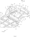
FIG. 1 illustrates a perspective view of a rear frame for a vehicle according to an exemplary embodiment of the present disclosure, which is mounted on a vehicle rear structure; -
FIG. 2 illustrates a perspective view of a rear frame for a vehicle according to an exemplary embodiment of the present disclosure; -
FIG. 3 illustrates a plan view of a rear frame for a vehicle according to an exemplary embodiment of the present disclosure; -
FIG. 4 illustrates a bottom view of a rear frame for a vehicle according to an exemplary embodiment of the present disclosure; -
FIG. 5 illustrates a side view of the rear frame, which is viewed in a direction of arrow A illustrated inFIG. 3 ; -
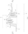
FIG. 6 illustrates a cross-sectional view taken along line B-B ofFIG. 3 ; -
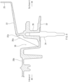
FIG. 7 illustrates a cross-sectional view taken along line C-C ofFIG. 5 ; -
FIG. 8 illustrates a cross-sectional view taken along line D-D ofFIG. 5 ; -
FIG. 9 illustrates a cross-sectional view taken along line E-E ofFIG. 5 ; -
FIG. 10 illustrates a bottom view of a state in which a rear subframe is mounted on a side portion of a rear frame for a vehicle according to an exemplary embodiment of the present disclosure; -
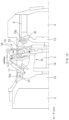
FIG. 11 illustrates a cross-sectional view taken along line F-F ofFIG. 10 ; -
FIG. 12 illustrates a perspective view of a front recessed structure of a rear frame for a vehicle according to an exemplary embodiment of the present disclosure; and -
FIG. 13 illustrates a perspective view of a rear recessed structure of a rear frame for a vehicle according to an exemplary embodiment of the present disclosure. - Hereinafter, exemplary embodiments of the present disclosure will be described in detail with reference to the accompanying drawings. In the drawings, the same reference numerals will be used throughout to designate the same or equivalent elements. In addition, a detailed description of well-known techniques associated with the present disclosure will be omitted in order not to unnecessarily obscure the gist of the present disclosure.
- Terms such as first, second, A, B, (a), and (b) may be used to describe the elements in exemplary embodiments of the present disclosure. These terms are only used to distinguish one element from another element, and the intrinsic features, sequence, order, and the like of the corresponding elements are not limited by the terms. Unless otherwise defined, all terms used herein, including technical or scientific terms, have the same meanings as those generally understood by those with ordinary knowledge in the field of art to which the present disclosure belongs. Such terms as those defined in a generally used dictionary are to be interpreted as having meanings equal to the contextual meanings in the relevant field of art and are not to be interpreted as having ideal or excessively formal meanings unless clearly defined as having such in the present application.
- Referring to
FIG. 1 , arear frame 10 for a vehicle according to an exemplary embodiment of the present disclosure may include a pair ofside portions 11 spaced apart from each other in a width direction of the vehicle, afirst cross portion 12 connecting front portions of the pair ofside portions 11, and asecond cross portion 13 connecting rear portions of the pair ofside portions 11. The pair ofside portions 11, thefirst cross portion 12, and thesecond cross portion 13 may form a unitary one-piece structure by a casting method. In a rear frame according to the related art, a pair of rear side members, a first crossmember, and a second crossmember may be individually manufactured, and then the pair of rear side members, the first crossmember, and the second crossmember may be joined using various fasteners. On the other hand, according to an exemplary embodiment of the present disclosure, the pair ofside portions 11, thefirst cross portion 12, and thesecond cross portion 13 may form a unitary one-piece structure so that there may be no joints made by welding, fasteners, brackets, reinforcements, etc. Accordingly, a load may be uniformly distributed or transferred through the pair of side portions and the plurality of cross portions. According to the related art, as fractures or damage occur at joints between the rear side members and the crossmembers, stiffness of the rear frame may be reduced. On the other hand, since therear frame 10 according to an exemplary embodiment of the present disclosure has no joints between eachside portion 11 and thecross portions rear frame 10 may be prevented. Not only mounting stiffness of related components connected to therear frame 10 and stiffness thereof at mounting points but also rear crashworthiness (strength to withstand a rear crash or impact) may be significantly improved. - The
rear frame 10 may be connected to a rear edge of acenter floor 1 of the vehicle, and a pair ofside sills 1a may be mounted at both side edges of thecenter floor 1. A plurality ofrear floor panels rear frame 10. The plurality ofrear floor panels rear floor panel 2 connected to the rear edge of thecenter floor 1, a secondrear floor panel 3 located behind the firstrear floor panel 2, and a storage well 4 located behind the secondrear floor panel 3. - A front edge of the first
rear floor panel 2 may be fixed to the rear edge of thecenter floor 1 using fasteners, welding, and/or the like. A plurality oflongitudinal members 6 may be fixed to the firstrear floor panel 2 using fasteners, welding, and/or the like, and a rear end of eachlongitudinal member 6 may be fixed to thefirst cross portion 12 using fasteners, welding, and/or the like. A rear edge of the firstrear floor panel 2 may be fixed to a front edge of thefirst cross portion 12 using fasteners, welding, and/or the like. - The second
rear floor panel 3 may be mounted between the pair ofside portions 11, thefirst cross portion 12, and thesecond cross portion 13. The secondrear floor panel 3 may be located higher than the firstrear floor panel 2. A front edge of the secondrear floor panel 3 may be fixed to thefirst cross portion 12 using fasteners, welding, and/or the like, and a rear edge of the secondrear floor panel 3 may be fixed to thesecond cross portion 13 using fasteners, welding, and/or the like. Each side edge of the secondrear floor panel 3 may be fixed to thecorresponding side portion 11 using fasteners, welding, and/or the like. - Referring to
FIG. 1 , therear frame 10 according to an exemplary embodiment of the present disclosure may further include asupport member 14 extending along a longitudinal direction of the vehicle between thefirst cross portion 12 and thesecond cross portion 13. A front end of thesupport member 14 may be fixed to a middle portion of thefirst cross portion 12, and a rear end of thesupport member 14 may be fixed to a middle portion of thesecond cross portion 13. Accordingly, thesupport member 14 may connect thefirst cross portion 12 and thesecond cross portion 13 in the longitudinal direction of the vehicle, thereby significantly improving longitudinal stiffness of therear frame 10. In addition, thesupport member 14 may be mounted transverse to thefirst cross portion 12 and thesecond cross portion 13 so that thesupport member 14 may firmly support the secondrear floor panel 3. - The storage well 4 may be recessed downward with respect to the second
rear floor panel 3, and a front edge of the storage well 4 may be fixed to thesecond cross portion 13 using fasteners, welding, and/or the like. A pair ofrear extension members 9 may be fixed to both side edges of the storage well 4 using fasteners, welding, and/or the like. Aback panel 5 may be fixed to a rear edge of the storage well 4 using fasteners, welding, and/or the like. - A pair of wheel house
inner panels 7 may be mounted on the pair ofside portions 11, respectively. Each wheel houseinner panel 7 may be fixed to thecorresponding side portion 11 using fasteners, welding, and/or the like. - Referring to
FIG. 2 , the pair ofside portions 11 may be spaced apart from each other in the width direction of the vehicle. Eachside portion 11 may extend in the longitudinal direction of the vehicle so that theside portions 11 may define both side edges of a vehicle rear structure. - Each
side portion 11 may include adamper receptacle 23 in which asuspension damper 16 is mounted, a fronttop wall 21 extending from thedamper receptacle 23 toward the front of the vehicle, and a reartop wall 22 extending from thedamper receptacle 23 toward the rear of the vehicle. A front end of theside portion 11 may be connected to thecorresponding side sill 1a, and a rear end of theside portion 11 may be connected to the correspondingrear extension member 9. - Referring to
FIGS. 4 ,10 , and11 , thedamper receptacle 23 may have a pocket shape having acavity 23e with an open bottom. An upper portion of thesuspension damper 16 such as a shock absorber may be received in thecavity 23e of thedamper receptacle 23, and the upper portion of thesuspension damper 16 may be mounted in thecavity 23e of thedamper receptacle 23. Thedamper receptacle 23 may include atop wall 23a, anoutboard wall 23b extending downward from an outboard edge of thetop wall 23a, and aninboard wall 23c extending downward from an inboard edge of thetop wall 23a. Thecavity 23e may be defined by thetop wall 23a, theoutboard wall 23b, and theinboard wall 23c. A front end of theoutboard wall 23b may be connected to a front end of theinboard wall 23c, and a rear end of theoutboard wall 23b may be connected to a rear end of theinboard wall 23c. Thedamper receptacle 23 may further include a raisedwall 23d which is raised upward from thetop wall 23a. - A front end of the front
top wall 21 may be connected to thecorresponding side sill 1a, and a rear end of the fronttop wall 21 may be integrally connected to a front end of thedamper receptacle 23. - Referring to
FIG. 7 , a frontinboard wall 21a may be a vertical wall extending vertically downward from the fronttop wall 21, and the frontinboard wall 21a may face the interior of the vehicle. The frontinboard wall 21a may extend along a center line between an outboard edge of theside portion 11 and an inboard edge of theside portion 11. In particular, the frontinboard wall 21a may extend along a center line of thedamper receptacle 23. - A front end of the rear
top wall 22 may be integrally connected to a rear end of thedamper receptacle 23. A rear end of the reartop wall 22 may be integrally connected to a front end of the correspondingrear extension member 9. The reartop wall 22 may have arear portion 22b receiving a front portion of therear extension member 9 and aninboard wall 22c. - Referring to
FIG. 8 , a rearinboard wall 22a may be a vertical wall extending vertically downward from the reartop wall 22, and the rearinboard wall 22a may face the interior of the vehicle. The rearinboard wall 22a may extend along the center line between the outboard edge of theside portion 11 and the inboard edge of theside portion 11. In particular, the rearinboard wall 22a may extend along the center line of thedamper receptacle 23. - As described above, the front
inboard wall 21a may extend from thedamper receptacle 23 toward the front of the vehicle, the rearinboard wall 22a may extend from thedamper receptacle 23 toward the rear of the vehicle, and the frontinboard wall 21a and the rearinboard wall 22a may be integrally connected to thedamper receptacle 23 so that stiffness of thedamper receptacle 23 may be improved, and thus a load applied by thesuspension damper 16 may be distributed through the frontinboard wall 21a and the rearinboard wall 22a. - Referring to
FIG. 2 , eachside portion 11 may further include afront flange 28a formed on a front portion of the frontinboard wall 21a, and thefront flange 28a may extend horizontally from the frontinboard wall 21a. Eachside portion 11 may include anoutboard flange 26 extending along an outboard edge of the fronttop wall 21, the outboard edge of thetop wall 23a of thedamper receptacle 23, and an outboard edge of the reartop wall 22. The wheel houseinner panel 7 may be fixed to theoutboard flange 26 of theside portion 11, and a wheelhouse reinforcing member 8 may be fixed to a middle portion of the wheel houseinner panel 7 using fasteners, welding, and/or the like. The wheelhouse reinforcing member 8 may have a channel shape bent along a top surface and an inboard surface of the wheel houseinner panel 7. The wheelhouse reinforcing member 8 may include a front wall facing the front of the vehicle, a rear wall facing the rear of the vehicle, and an inboard wall facing the interior of the vehicle. - Referring to
FIGS. 1 and2 , eachside portion 11 may further include achannel portion 27 protruding upward from the fronttop wall 21 and thedamper receptacle 23. A portion of the wheel houseinner panel 7 and a bottom end of the wheelhouse reinforcing member 8 may be fixed to thechannel portion 27 using fasteners, welding, and/or the like. - Referring to
FIGS. 3 and5 , thechannel portion 27 may have a pocket shape having acavity 27e with an open top. Thechannel portion 27 may include aninboard wall 27a facing the interior of the vehicle, anoutboard wall 27b facing the exterior of the vehicle, afront wall 27c facing the front of the vehicle, arear wall 27d facing the rear of the vehicle, and abottom wall 27f facing the bottom of the vehicle. Thecavity 27e may be defined by theinboard wall 27a, theoutboard wall 27b, thefront wall 27c, therear wall 27d, and thebottom wall 27f. The bottom end of the wheelhouse reinforcing member 8 may be fixed to theinboard wall 27a, thefront wall 27c, and therear wall 27d of thechannel portion 27 using fasteners, welding, and/or the like. A portion of the wheel houseinner panel 7 may be fixed to theoutboard wall 27b of thechannel portion 27 using fasteners, welding, and/or the like. - Since the
channel portion 27 has a pocket shape with an open top, an electrodeposition coating solution may be stagnated in thecavity 27e of thechannel portion 27 during electrodeposition coating of therear frame 10, and the electrodeposition coating solution remaining in thecavity 27e of thechannel portion 27 may be burned during baking in the electrodeposition coating process. To solve this problem, thechannel portion 27 may have a throughhole 71 formed in thebottom wall 27f, and the throughhole 71 may be open to the outside of thechannel portion 27. The electrodeposition coating solution may be discharged through the throughhole 71 of thechannel portion 27 so that the electrodeposition coating solution may not remain in thecavity 27e of thechannel portion 27. - Each
side portion 11 may further include a first inboardhorizontal wall 28b extending horizontally from the frontinboard wall 21a, theinboard wall 23c of thedamper receptacle 23, and the rearinboard wall 22a toward the interior of the vehicle, an inboardvertical wall 28d extending vertically downward from the first inboardhorizontal wall 28b, and a second inboardhorizontal wall 28c extending horizontally from the inboardvertical wall 28d. - The
first cross portion 12 may be configured to connect the front portions of the pair ofside portions 11 in the width direction of the vehicle. The front edge of thefirst cross portion 12 may be fixed to the rear edge of the firstrear floor panel 2, and a rear edge of thefirst cross portion 12 may be fixed to the front edge of the secondrear floor panel 3. - Referring to
FIG. 2 , thefirst cross portion 12 may include atop wall 41, avertical wall 42 extending vertically downward from a front edge of thetop wall 41, and abottom wall 43 extending from a bottom edge of thevertical wall 42 toward the front of the vehicle. A height of thetop wall 41 may be the same as or similar to a height of thesecond cross portion 13. Stiffness of thefirst cross portion 12 may be improved by thetop wall 41, thevertical wall 42, and thebottom wall 43. - Referring to
FIGS. 2 and6 , thefirst cross portion 12 may include a recessedwall 44 which is recessed from thebottom wall 43 toward the bottom of the vehicle, a plurality of raisedwalls 45 which are raised upward from the recessedwall 44, and afront flange 47 which is recessed downward from a front edge of the recessedwall 44. - Referring to
FIG. 2 , the plurality of raisedwalls 45 may be adjacent to the front edge of the recessedwall 44, and the plurality of raisedwalls 45 may be spaced apart from each other in the width direction of the vehicle (that is, in a longitudinal direction of the first cross portion 12) so that a plurality ofpassages 46 may be formed between the plurality of raisedwalls 45, and a top surface of eachpassage 46 may be flush with a top surface of the recessedwall 44. When the electrodeposition coating solution flows down to the recessedwall 44 during the electrodeposition coating of therear frame 10, the electrodeposition coating solution may be discharged through the plurality ofpassages 46 so that the electrodeposition coating solution may not remain in the recessedwall 44. - The rear edge of the first
rear floor panel 2 may be fixed to thefront flange 47 of thefirst cross portion 12 and thefront flange 28a of theside portion 11 using fasteners, welding, and/or the like. - Referring to
FIGS. 4 and5 , eachside portion 11 may include afront mounting surface 31 provided on a bottom surface of the front portion thereof and arear mounting surface 32 provided on a bottom surface of the rear portion thereof. Arear subframe 15 may include a pair offront mounts 15a and a pair ofrear mounts 15b. Eachfront mount 15a of therear subframe 15 may be mounted on the correspondingfront mounting surface 31, and eachrear mount 15b of therear subframe 15 may be mounted on the correspondingrear mounting surface 32. Thedamper receptacle 23 may be located between the front mountingsurface 31 and therear mounting surface 32. - The front mounting
surface 31 may be integrally formed with a portion of the frontinboard wall 21a at a bottom edge of the frontinboard wall 21a. Referring toFIGS. 3 and4 , thefront mounting surface 31 may have a substantially circular shape, and the frontinboard wall 21a may extend through a center line of the front mountingsurface 31 or a line adjacent thereto. The front mountingsurface 31 may be integrally connected to the frontinboard wall 21a. - Referring to
FIG. 7 , thefront mounting surface 31 may be horizontally flat at a bottom edge of a bottom surface of the frontinboard wall 21a. Eachside portion 11 may include a front mountingboss 35 located at the center of the front mountingsurface 31. The center line of the front mountingsurface 31 may be aligned with the center line of thecorresponding side portion 11, and accordingly the front mountingboss 35 may be aligned with the center line of the front mountingsurface 31 and the center line of thecorresponding side portion 11. The front mountingboss 35 may be formed on a front lower portion of the frontinboard wall 21a, and the front mountingboss 35 may extend vertically along the frontinboard wall 21a.Front mounting hardware 33 may be fixed to the front mountingboss 35, and the center of the front mountinghardware 33 may be aligned with the center of the front mountingboss 35. Thefront mounting hardware 33 may have a nut shape. Referring toFIG. 10 , thefront mount 15a of therear subframe 15 may be mounted on thefront mounting surface 31 through thefront mounting hardware 33. - According to the related art, each rear side member may have a front mounting boss formed on a front portion thereof, and each front mount of a rear subframe may be mounted on the corresponding front mounting boss. As the front mounting boss is formed on a front lower portion of an inboard wall of the rear side member, and the inboard wall of the rear side member is adj acent to an inboard edge of the rear side member, the front mounting boss may be formed to have a relatively large thickness, which may degrade castability of the rear side member and cause the formation of a plurality of pores in the front mounting boss, resulting in reduced casting quality. On the other hand, according to an exemplary embodiment of the present disclosure, the front
inboard wall 21a may extend along the center line between the outboard edge of theside portion 11 and the inboard edge of theside portion 11 so that the thickness of the front mountingboss 35 formed on the front lower portion of the frontinboard wall 21a may be relatively reduced. Accordingly, castability of theside portion 11 may be improved, and pores may not be formed in the front mountingboss 35, resulting in improved casting quality. - Referring to
FIG. 7 , eachside portion 11 may include a front recessedstructure 37 formed on thefront mounting surface 31. As the front recessedstructure 37 is formed on thefront mounting surface 31, castability of theside portion 11 may be improved. As thefront mounting surface 31 is formed at the bottom edge of the frontinboard wall 21a, the front recessedstructure 37 may be recessed downward between the frontinboard wall 21a and thefirst cross portion 12. Accordingly, the front recessedstructure 37 may be defined by the frontinboard wall 21a, thebottom wall 43 of thefirst cross portion 12, and the front mountingsurface 31, and the front recessedstructure 37 may have a pocket shape with an open top. Referring toFIG. 12 , the front recessedstructure 37 may have a substantially semicircular pocket shape facing the frontinboard wall 21a. The front recessedstructure 37 may have a front reinforcingrib 35a extending from the frontinboard wall 21a toward the interior of the vehicle. The front reinforcingrib 35a may extend from the front mountingboss 35 of the frontinboard wall 21a toward thebottom wall 43 of thefirst cross portion 12 so that the front reinforcingrib 35a may extend through the front recessedstructure 37. The front reinforcingrib 35a may extend in the width direction of the vehicle, and the front reinforcingrib 35a may be perpendicular to the frontinboard wall 21a. Accordingly, stiffness of the front recessedstructure 37 may be improved by thefront reinforcing rib 35a. - Since the front recessed
structure 37 has a pocket shape with an open top, the electrodeposition coating solution may be stagnated in the inside of the front recessedstructure 37 during the electrodeposition coating of therear frame 10, and the electrodeposition coating solution remaining in the front recessedstructure 37 may be burned during baking in the electrodeposition coating process. To solve this problem, a throughhole 72 may be formed in a portion of the frontinboard wall 21a defining the front recessedstructure 37, and the throughhole 72 may be open to the outside of the front recessedstructure 37. According to an exemplary embodiment, the throughhole 72 may extend obliquely from the frontinboard wall 21a toward the exterior of the vehicle, and the throughhole 72 may directly communicate with the front recessedstructure 37. Accordingly, the electrodeposition coating solution received in the front recessedstructure 37 may be discharged through the throughhole 72 of the front recessedstructure 37 so that the electrodeposition coating solution may not remain in the front recessedstructure 37. - The
rear mounting surface 32 may be integrally formed with a portion of the rearinboard wall 22a at a bottom edge of the rearinboard wall 22a. Referring toFIGS. 3 and4 , therear mounting surface 32 may have a substantially circular shape, and the rearinboard wall 22a may extend through a center line of therear mounting surface 32 or a line adjacent thereto. Therear mounting surface 32 may be integrally connected to the rearinboard wall 22a. - Referring to
FIG. 8 , therear mounting surface 32 may be horizontally flat at a bottom edge of a bottom surface of the rearinboard wall 22a. Eachside portion 11 may include arear mounting boss 36 located at the center of therear mounting surface 32. The center line of therear mounting surface 32 may be aligned with the center line of thecorresponding side portion 11, and accordingly therear mounting boss 36 may be aligned with the center line of theside portion 11 and the center line of the correspondingrear mounting surface 32. Therear mounting boss 36 may be formed on a rear lower portion of the rearinboard wall 22a, and therear mounting boss 36 may extend vertically along the rearinboard wall 22a.Rear mounting hardware 34 may be fixed to therear mounting boss 36, and the center of therear mounting hardware 34 may be aligned with the center of therear mounting boss 36. Therear mounting hardware 34 may have a bolt shape. Referring toFIG. 10 , therear mount 15b of therear subframe 15 may be mounted on therear mounting surface 32 through therear mounting hardware 34. - According to the related art, each rear side member may have a rear mounting boss formed on a rear portion thereof, and each rear mount of the rear subframe may be mounted on the corresponding rear mounting boss. As the rear mounting boss is formed on a rear lower portion of the inboard wall of the rear side member, and the inboard wall of the rear side member is adjacent to the inboard edge of the rear side member, the rear mounting boss may be formed to have a relatively large thickness, which may degrade castability of the rear side member, and cause the formation of a plurality of pores in the rear mounting boss, resulting in reduced casting quality. On the other hand, according to an exemplary embodiment of the present disclosure, the rear
inboard wall 22a may extend along the center line between the outboard edge of theside portion 11 and the inboard edge of theside portion 11 so that the thickness of therear mounting boss 36 formed on the rear lower portion of the rearinboard wall 22a may be relatively reduced. Accordingly, castability of theside portion 11 may be improved, and pores may not be formed in therear mounting boss 36, resulting in improved casting quality. - Referring to
FIG. 8 , eachside portion 11 may include a rear recessedstructure 38 formed on therear mounting surface 32. As the rear recessedstructure 38 is formed on therear mounting surface 32, castability of theside portion 11 may be improved. As therear mounting surface 32 is formed at the bottom edge of the rearinboard wall 22a, the rear recessedstructure 38 may be recessed downward between the rearinboard wall 22a and the first inboardhorizontal wall 28b. Accordingly, the rear recessedstructure 38 may be defined by the rearinboard wall 22a, the first inboardhorizontal wall 28b of theside portion 11, and therear mounting surface 32, and the rear recessedstructure 38 may have a pocket shape with an open top. Referring toFIG. 13 , the rear recessedstructure 38 may have a substantially semicircular pocket shape facing the rearinboard wall 22a. The rear recessedstructure 38 may have arear reinforcing rib 36a extending from the rearinboard wall 22a toward the interior of the vehicle. Therear reinforcing rib 36a may extend from therear mounting boss 36 of the rearinboard wall 22a toward the first inboardhorizontal wall 28b of theside portion 11 so that therear reinforcing rib 36a may extend through the rear recessedstructure 38. Therear reinforcing rib 36a may extend in the width direction of the vehicle, and therear reinforcing rib 36a may be perpendicular to the rearinboard wall 22a. Accordingly, stiffness of the rear recessedstructure 38 may be improved by therear reinforcing rib 36a. - Since the rear recessed
structure 38 has a pocket shape with an open top, the electrodeposition coating solution may be stagnated in the inside of the rear recessedstructure 38 during the electrodeposition coating of therear frame 10, and the electrodeposition coating solution remaining in the rear recessedstructure 38 may be burned during baking in the electrodeposition coating process. To solve this problem, a throughhole 73 may be formed in a portion of the rearinboard wall 22a defining the rear recessedstructure 38, and the throughhole 73 may be open to the outside of the rear recessedstructure 38. According to an exemplary embodiment, the throughhole 73 may extend obliquely from the rearinboard wall 22a toward the exterior of the vehicle, and the throughhole 73 may directly communicate with the rear recessedstructure 38. Accordingly, the electrodeposition coating solution received in the rear recessedstructure 38 may be discharged through the throughhole 73 so that the electrodeposition coating solution may not remain in the rear recessedstructure 38. - As described above, the front
inboard walls 21a may be integrally connected to the correspondingfront mounting surfaces 31, the rearinboard walls 22a may be integrally connected to the correspondingrear mounting surfaces 32, the front mounts 15a of therear subframe 15 may be mounted on the correspondingfront mounting surfaces 31, and the rear mounts 15b of therear subframe 15 may be mounted on the correspondingrear mounting surfaces 32 so that therear subframe 15 mounted on the pair ofside portions 11 may be stably supported by the frontinboard walls 21a and the rearinboard walls 22a along the longitudinal direction of the vehicle. - The rear end of each
side portion 11 may be connected to the correspondingrear extension member 9. The rearinboard wall 22a of eachside portion 11 may be fixed to therear extension member 9. Referring toFIGS. 5 and9 , the rearinboard wall 22a may include a plurality of rear extensionmember mounting bosses 51 provided on a rear portion thereof, and each rear extensionmember mounting boss 51 may have a mounting hole defined therein. The front portion of therear extension member 9 may be fixed to the rear extensionmember mounting boss 51 of the rearinboard wall 22a through abolt 81. Mounting hardware such as a tappingnut 61 may be mounted in the mounting hole of the corresponding rear extensionmember mounting boss 51. The tappingnut 61 may haveinternal threads 61a formed on an inner surface thereof andexternal threads 61b formed on an outer surface thereof. The rear extensionmember mounting boss 51 may be tapped by theexternal threads 61b of the tappingnut 61 so that the tappingnut 61 may be mounted in the rear extensionmember mounting boss 51, andexternal threads 81a of thebolt 81 may be engaged with theinternal threads 61a of the tappingnut 61 so that the front portion of therear extension member 9 may be mounted on the rear extensionmember mounting boss 51 of the rearinboard wall 22a. - Referring to
FIG. 3 , thefirst cross portion 12 may include a plurality of seat-side mounting bosses 52 adjacent to the front edge thereof. The plurality of seat-side mounting bosses 52 may be spaced apart from each other in the width direction of the vehicle. Each seat-side mounting boss 52 may have a mounting hole defined therein. Referring toFIG. 6 , the seat-side mounting boss 52 may protrude upward from the raisedwall 45 of thefirst cross portion 12, and arear seat mount 17 for a rear vehicle seat (for example, a second-row vehicle seat) may be mounted on the seat-side mounting boss 52 through a bolt. Mounting hardware such as a tappingnut 62 may be mounted in the mounting hole of the corresponding seat-side mounting boss 52. The tappingnut 62 may haveinternal threads 62a formed on an inner surface thereof andexternal threads 62b formed on an outer surface thereof. The seat-side mounting boss 52 may be tapped by theexternal threads 62b of the tappingnut 62 so that the tappingnut 62 may be mounted in the seat-side mounting boss 52, and external threads of the bolt may be engaged with theinternal threads 62a of the tappingnut 62 so that therear seat mount 17 may be mounted on the seat-side mounting boss 52 of thefirst cross portion 12. The plurality of seat-side mounting bosses 52 may be disposed symmetrically with respect to the center of thefirst cross portion 12. - Referring to
FIG. 3 , thefirst cross portion 12 may include a plurality of battery-side mounting bosses 53 adjacent to the plurality of seat-side mounting bosses 52. The plurality of battery-side mounting bosses 53 may be spaced apart from each other in the width direction of the vehicle. Each battery-side mounting boss 53 may have a mounting hole defined therein. Referring toFIG. 6 , the battery-side mounting boss 53 may be located behind the seat-side mounting boss 52, the battery-side mounting boss 53 may protrude downward from the raisedwall 45 of thefirst cross portion 12, and abattery 18 may be mounted on the battery-side mounting boss 53 through a bolt. Mounting hardware such as a tappingnut 63 may be mounted in the mounting hole of the corresponding battery-side mounting boss 53. The tappingnut 63 may have internal threads 63a formed on an inner surface thereof andexternal threads 63b formed on an outer surface thereof. The battery-side mounting boss 53 may be tapped by theexternal threads 63b of the tappingnut 63 so that the tappingnut 63 may be mounted in the battery-side mounting boss 53, and external threads of the bolt may be engaged with the internal threads 63a of the tappingnut 63 so that thebattery 18 may be mounted on the battery-side mounting boss 53 of thefirst cross portion 12. The plurality of battery-side mounting bosses 53 may be disposed symmetrically with respect to the center of thefirst cross portion 12. - Referring to
FIG. 3 , thefirst cross portion 12 may include a plurality of first mountingbosses 54 adjacent to the rear edge thereof, and each first mountingboss 54 may have a mounting hole defined therein. A front seat mount for a vehicle seat (for example, a third-row vehicle seat) located at the rearmost section of a cabin of the vehicle may be mounted on the first mountingboss 54 of thefirst cross portion 12 through a bolt. - Referring to
FIG. 3 , thesecond cross portion 13 may include a plurality of second mountingbosses 55, and each second mountingboss 55 may have a mounting hole defined therein. A rear seat mount for a vehicle seat (for example, a third-row vehicle seat) located at the rearmost section of the cabin of the vehicle may be mounted on the second mountingboss 55 of thesecond cross portion 13 through a bolt. - Referring to
FIG. 4 , eachside portion 11 may include a plurality of reinforcingribs ribs rib 11a extending in a longitudinal direction of theside portion 11, a plurality of second reinforcingribs 11b extending in a diagonal direction, and a plurality of third reinforcingribs 11c extending in a width direction of theside portion 11. The first reinforcingrib 11a may be spaced apart from the frontinboard wall 21a, thedamper receptacle 23, and the rearinboard wall 22a toward the interior of the vehicle. The plurality of reinforcingribs side portion 11, and the plurality of reinforcingribs inboard wall 21a, theinboard wall 23c of thedamper receptacle 23, and the rearinboard wall 22a. The plurality of second reinforcingribs 11b may connect thedamper receptacle 23 to the first reinforcingrib 11a, and the plurality of third reinforcingribs 11c may connect the frontinboard wall 21a and the rearinboard wall 22a to the first reinforcingrib 11a. Accordingly, stiffness of theside portion 11 and thedamper receptacle 23 may be improved by the plurality of reinforcingribs - Referring to
FIG. 5 , eachside portion 11 may include a plurality of reinforcingribs 11f integrally formed with the frontinboard wall 21a, theinboard wall 23c of thedamper receptacle 23, and the rearinboard wall 22a, and the plurality of reinforcingribs 11f may intersect and be connected to each other in the longitudinal direction of theside portion 11. Accordingly, lateral stiffness of theside portion 11 may be improved by the plurality of reinforcingribs 11f. - Referring to
FIG. 4 , thefirst cross portion 12 may include a plurality of reinforcingribs ribs ribs 12a extending in the width direction of the vehicle, a plurality of second reinforcingribs 12b extending in the longitudinal direction of the vehicle, and a plurality of third reinforcingribs 12c extending in a diagonal direction. The plurality of reinforcingribs first cross portion 12 may be improved by the plurality of reinforcingribs ribs side mounting bosses 53. For example, the first reinforcingrib 12a, the second reinforcingrib 12b, and the third reinforcingrib 12c may be connected to each battery-side mounting boss 53 while intersecting each other so that stiffness of the plurality of battery-side mounting bosses 53 may be improved. - Referring to
FIG. 4 , thefirst cross portion 12 may include a plurality of reinforcingribs bosses 54. The plurality of reinforcingribs ribs 54a extending in the width direction of the vehicle, a plurality of second reinforcingribs 54b extending in a diagonal direction, and a plurality of third reinforcingribs 54c extending in the longitudinal direction of the vehicle. For example, the first reinforcingrib 54a may be connected to the first mountingbosses 54 adjacent to a center line of therear frame 10. The first reinforcingrib 54a, the second reinforcingrib 54b, and the third reinforcingrib 54c may be connected to the first mountingboss 54 adjacent to each end of thefirst cross portion 12 while intersecting each other. - Referring to
FIG. 4 , thesecond cross portion 13 may include a plurality of reinforcingribs ribs ribs 13a extending in the width direction of the vehicle and a plurality of second reinforcingribs 13b extending in a diagonal direction. The plurality of reinforcingribs second cross portion 13 may be improved by the plurality of reinforcingribs - Referring to
FIG. 4 , thesecond cross portion 13 may include a plurality of reinforcingribs bosses 55. The plurality of reinforcingribs ribs 55a extending in the longitudinal direction of the vehicle, a plurality of second reinforcingribs 55b extending in a diagonal direction, and a plurality of third reinforcingribs 55c extending in the width direction of the vehicle. For example, the first reinforcingrib 55a, the second reinforcingrib 55b, and the third reinforcingrib 55c may be connected to the second mountingboss 55 while intersecting each other. - As set forth above, the rear frame according to exemplary embodiments of the present disclosure may be designed to have the pair of side portions and the plurality of cross portions forming a unitary one-piece structure by the casting method so that stiffness of the vehicle rear structure may be improved. In particular, as the pair of side portions and the plurality of cross portions form a unitary one-piece structure, there may be no joints made by welding, fasteners, brackets, reinforcements, etc. Accordingly, the load may be uniformly distributed or transferred through the pair of side portions and the plurality of cross portions. According to the related art, as fractures or damage occur at the joints between the rear side members and the crossmembers, stiffness of the rear frame may be reduced. On the other hand, as the rear frame according to exemplary embodiments of the present disclosure has no joints between each side portion and the cross portions, a decrease in stiffness at the joints of the rear frame may be prevented. Not only the mounting stiffness of related components connected to the rear frame and stiffness thereof at the mounting points but also rear crashworthiness (strength to withstand a rear crash or impact) may be significantly improved.
- According to exemplary embodiments of the present disclosure, as the pair of side portions and the plurality of cross portions form a unitary one-piece structure, the number of components and the number of joints may be reduced so that the manufacturing cost may be reduced.
- According to exemplary embodiments of the present disclosure, the front inboard wall may extend from the damper receptacle toward the front of the vehicle, the rear inboard wall may extend from the damper receptacle toward the rear of the vehicle, and the front inboard wall and the rear inboard wall may be integrally connected to the damper receptacle so that stiffness of the damper receptacle may be improved, and thus the load applied by the suspension damper may be distributed through the front inboard wall and the rear inboard wall.
- Hereinabove, although embodiments of the present disclosure have been described with reference to exemplary embodiments and the accompanying drawings, the present disclosure is not limited thereto, but it may be variously modified and altered by those skilled in the art to which the present disclosure pertains without departing from the spirit and scope of the present disclosure claimed in the following claims.
Claims (20)
- A rear frame comprising:a pair of side portions spaced apart from each other in a width direction of a vehicle, each side portion having a damper receptacle in which a suspension damper is mounted;a first cross portion connecting front portions of the pair of side portions; anda second cross portion connecting rear portions of the pair of side portions, wherein the pair of side portions, the first cross portion, and the second cross portion together are a unitary one-piece structure.
- The rear frame according to claim 1, wherein the damper receptacle has a pocket shape having a cavity with an open bottom.
- The rear frame according to claim 1 or 2, wherein:the first cross portion comprises a plurality of seat-side mounting bosses on which a seat mount for a vehicle seat is mounted;each seat-side mounting boss protrudes upward from the first cross portion; andmounting hardware is mounted in a mounting hole of the corresponding seat-side mounting boss.
- The rear frame according to claim 3, wherein the seat-side mounting bosses are disposed symmetrically with respect to a center of the first cross portion.
- The rear frame according to one of claims 1-4, wherein:the first cross portion comprises a plurality of battery-side mounting bosses on which a battery is mounted;each battery-side mounting boss protrudes downward from the first cross portion; andmounting hardware is mounted in a mounting hole of the corresponding battery-side mounting boss.
- The rear frame according to claim 5, wherein the battery-side mounting bosses are disposed symmetrically with respect to a center of the first cross portion.
- The rear frame according to claim 5 or 6, wherein the first cross portion comprises a plurality of reinforcing ribs intersecting and connected to the battery-side mounting bosses.
- The rear frame according to one of claims 1-7, wherein the second cross portion comprises a plurality of reinforcing ribs disposed on a bottom surface thereof.
- The rear frame according to one of claims 1-8, wherein:each side portion comprises a plurality of reinforcing ribs disposed on a bottom surface thereof; andthe plurality of reinforcing ribs comprises a first reinforcing rib extending in a longitudinal direction of the corresponding side portion and a plurality of second reinforcing ribs connecting the damper receptacle to the first reinforcing rib.
- The rear frame according to claim 1, wherein each side portion comprisesa front inboard wall extending from the damper receptacle toward a front of the vehicle; anda rear inboard wall extending from the damper receptacle toward a rear of the vehicle, wherein the front inboard wall and the rear inboard wall extend along a center line between an inboard edge of the respective side portion and an outboard edge of the respective side portion.
- The rear frame according to claim 10, wherein:the rear inboard wall comprises a rear extension member mounting boss disposed on a rear portion thereof; anda front portion of a rear extension member is fixed to the rear extension member mounting boss through a fastener.
- The rear frame according to claim 10 or 11, wherein:each side portion comprises a front mounting surface disposed on a bottom surface of the front portion thereof and a rear mounting surface disposed on a bottom surface of the rear portion thereof;a front mount of a rear subframe is mounted on the front mounting surface; anda rear mount of the rear subframe is mounted on the rear mounting surface.
- The rear frame according to claim 12, wherein:the front mounting surface has a first substantially circular shape; andthe rear mounting surface has a second substantially circular shape.
- The rear frame according to claim 12 or 13, wherein the damper receptacle is disposed between the front mounting surface and the rear mounting surface.
- The rear frame according to one of claims 12-14, wherein:the front mounting surface is disposed at a bottom edge of the front inboard wall; andthe rear mounting surface is disposed at a bottom edge of the rear inboard wall.
- The rear frame according to one of claims 12-15, wherein:each side portion further comprises a front mounting boss disposed at a center of the front mounting surface, front mounting hardware fixed to the front mounting boss, a rear mounting boss disposed at a center of the rear mounting surface, and rear mounting hardware fixed to the rear mounting boss; andthe front mounting boss and the rear mounting surface are aligned with the center line of the respective side portion.
- The rear frame according to one of claims 12-16, wherein each side portion further comprises a front recessed structure disposed on the front mounting surface and a rear recessed structure disposed on the rear mounting surface.
- The rear frame according to claim 17, wherein:the front recessed structure has a first substantially semicircular pocket shape; andthe rear recessed structure has a second substantially semicircular pocket shape.
- The rear frame according to claim 17 or 18, wherein:the front recessed structure is defined by the front inboard wall and the front mounting surface; andthe front recessed structure has a front reinforcing rib extending from the front inboard wall toward an interior of the vehicle.
- The rear frame according to one of claims 17-19, wherein:the rear recessed structure is defined by the rear inboard wall and the rear mounting surface; andthe rear recessed structure has a rear reinforcing rib extending from the rear inboard wall toward an interior of the vehicle.
Applications Claiming Priority (1)
| Application Number | Priority Date | Filing Date | Title |
|---|---|---|---|
| KR1020230181220A KR20250090970A (en) | 2023-12-13 | 2023-12-13 | Rear frame for vehicle |
Publications (1)
| Publication Number | Publication Date |
|---|---|
| EP4570628A1 true EP4570628A1 (en) | 2025-06-18 |
Family
ID=91853312
Family Applications (1)
| Application Number | Title | Priority Date | Filing Date |
|---|---|---|---|
| EP24186774.6A Pending EP4570628A1 (en) | 2023-12-13 | 2024-07-05 | Rear frame for vehicle |
Country Status (5)
| Country | Link |
|---|---|
| US (1) | US20250196925A1 (en) |
| EP (1) | EP4570628A1 (en) |
| JP (1) | JP2025094886A (en) |
| KR (1) | KR20250090970A (en) |
| CN (1) | CN120135280A (en) |
Citations (3)
| Publication number | Priority date | Publication date | Assignee | Title |
|---|---|---|---|---|
| WO2022031991A1 (en) * | 2020-08-07 | 2022-02-10 | Tesla, Inc. | Integrated energy absorbing castings |
| WO2022223204A1 (en) * | 2021-04-20 | 2022-10-27 | Bayerische Motoren Werke Aktiengesellschaft | Rear structure for a motor vehicle and motor vehicle comprising such a rear structure |
| WO2023016106A1 (en) * | 2021-08-13 | 2023-02-16 | 长城汽车股份有限公司 | Lower vehicle body rear structure and vehicle |
Family Cites Families (6)
| Publication number | Priority date | Publication date | Assignee | Title |
|---|---|---|---|---|
| DE102011119561A1 (en) * | 2011-11-26 | 2013-05-29 | GM Global Technology Operations LLC (n. d. Gesetzen des Staates Delaware) | Support structure component for the body of a motor vehicle |
| JP7590107B2 (en) * | 2019-01-23 | 2024-11-26 | トヨタ自動車株式会社 | Body structural members |
| US11459035B1 (en) * | 2021-03-16 | 2022-10-04 | Ford Global Technologies, Llc | Shock absorber assembly structures |
| JP2023150061A (en) * | 2022-03-31 | 2023-10-16 | 本田技研工業株式会社 | Rear structure of vehicle body |
| KR20240074452A (en) * | 2022-11-21 | 2024-05-28 | 현대자동차주식회사 | Under body for vehicle |
| KR20240093091A (en) * | 2022-12-15 | 2024-06-24 | 현대자동차주식회사 | Body for vehicle |
-
2023
- 2023-12-13 KR KR1020230181220A patent/KR20250090970A/en active Pending
-
2024
- 2024-06-28 JP JP2024104755A patent/JP2025094886A/en active Pending
- 2024-07-05 EP EP24186774.6A patent/EP4570628A1/en active Pending
- 2024-07-08 US US18/765,611 patent/US20250196925A1/en active Pending
- 2024-11-12 CN CN202411605637.3A patent/CN120135280A/en active Pending
Patent Citations (4)
| Publication number | Priority date | Publication date | Assignee | Title |
|---|---|---|---|---|
| WO2022031991A1 (en) * | 2020-08-07 | 2022-02-10 | Tesla, Inc. | Integrated energy absorbing castings |
| WO2022223204A1 (en) * | 2021-04-20 | 2022-10-27 | Bayerische Motoren Werke Aktiengesellschaft | Rear structure for a motor vehicle and motor vehicle comprising such a rear structure |
| WO2023016106A1 (en) * | 2021-08-13 | 2023-02-16 | 长城汽车股份有限公司 | Lower vehicle body rear structure and vehicle |
| EP4385862A1 (en) * | 2021-08-13 | 2024-06-19 | Great Wall Motor Company Limited | Lower vehicle body rear structure and vehicle |
Also Published As
| Publication number | Publication date |
|---|---|
| CN120135280A (en) | 2025-06-13 |
| JP2025094886A (en) | 2025-06-25 |
| US20250196925A1 (en) | 2025-06-19 |
| KR20250090970A (en) | 2025-06-20 |
Similar Documents
| Publication | Publication Date | Title |
|---|---|---|
| US11524606B2 (en) | Vehicle floor structure | |
| US11813933B2 (en) | Vehicle floor structure | |
| US11351890B2 (en) | Seat crossmember and vehicle floor structure having the same | |
| CN110588800B (en) | Vehicle body lower structure | |
| US20250196931A1 (en) | Rear frame for vehicle | |
| KR102703743B1 (en) | Vehicle battery mounting structure | |
| WO2023016106A1 (en) | Lower vehicle body rear structure and vehicle | |
| CN217969656U (en) | Rear floor assembly and vehicle | |
| US11648982B2 (en) | Rear side structure for vehicle | |
| US11866098B2 (en) | Vehicle body structure | |
| KR20230067363A (en) | Vehicle floor system | |
| US12509161B2 (en) | Underbody for vehicle | |
| US11724743B2 (en) | Vehicle front structure | |
| US10046633B2 (en) | Vehicle rear portion structure | |
| US11299206B2 (en) | Vehicle structure for a cross-vehicle load path | |
| US20250196925A1 (en) | Rear frame for vehicle | |
| KR20220055293A (en) | Rear frame for vehicle | |
| US20250196726A1 (en) | Rear frame for vehicle | |
| CN112739610B (en) | Vehicle body lower structure | |
| KR102882423B1 (en) | Front structure for vehicle | |
| KR20260031329A (en) | Rear frame for vehicle | |
| KR20230022542A (en) | Front body structure | |
| JP2022097815A (en) | Structure of vehicular battery pack | |
| CN216916010U (en) | Longitudinal beam assembly of vehicle and vehicle | |
| CN211543231U (en) | Battery mounting structure and electric automobile |
Legal Events
| Date | Code | Title | Description |
|---|---|---|---|
| PUAI | Public reference made under article 153(3) epc to a published international application that has entered the european phase |
Free format text: ORIGINAL CODE: 0009012 |
|
| STAA | Information on the status of an ep patent application or granted ep patent |
Free format text: STATUS: THE APPLICATION HAS BEEN PUBLISHED |
|
| AK | Designated contracting states |
Kind code of ref document: A1 Designated state(s): AL AT BE BG CH CY CZ DE DK EE ES FI FR GB GR HR HU IE IS IT LI LT LU LV MC ME MK MT NL NO PL PT RO RS SE SI SK SM TR |
|
| STAA | Information on the status of an ep patent application or granted ep patent |
Free format text: STATUS: REQUEST FOR EXAMINATION WAS MADE |
|
| 17P | Request for examination filed |
Effective date: 20250730 |