EP4570613A1 - Steering control device - Google Patents
Steering control device Download PDFInfo
- Publication number
- EP4570613A1 EP4570613A1 EP24214325.3A EP24214325A EP4570613A1 EP 4570613 A1 EP4570613 A1 EP 4570613A1 EP 24214325 A EP24214325 A EP 24214325A EP 4570613 A1 EP4570613 A1 EP 4570613A1
- Authority
- EP
- European Patent Office
- Prior art keywords
- steering
- limiting
- value
- command value
- turning
- Prior art date
- Legal status (The legal status is an assumption and is not a legal conclusion. Google has not performed a legal analysis and makes no representation as to the accuracy of the status listed.)
- Pending
Links
Images



Classifications
-
- B—PERFORMING OPERATIONS; TRANSPORTING
- B62—LAND VEHICLES FOR TRAVELLING OTHERWISE THAN ON RAILS
- B62D—MOTOR VEHICLES; TRAILERS
- B62D15/00—Steering not otherwise provided for
- B62D15/02—Steering position indicators ; Steering position determination; Steering aids
- B62D15/029—Steering assistants using warnings or proposing actions to the driver without influencing the steering system
-
- B—PERFORMING OPERATIONS; TRANSPORTING
- B62—LAND VEHICLES FOR TRAVELLING OTHERWISE THAN ON RAILS
- B62D—MOTOR VEHICLES; TRAILERS
- B62D6/00—Arrangements for automatically controlling steering depending on driving conditions sensed and responded to, e.g. control circuits
- B62D6/008—Control of feed-back to the steering input member, e.g. simulating road feel in steer-by-wire applications
-
- B—PERFORMING OPERATIONS; TRANSPORTING
- B62—LAND VEHICLES FOR TRAVELLING OTHERWISE THAN ON RAILS
- B62D—MOTOR VEHICLES; TRAILERS
- B62D5/00—Power-assisted or power-driven steering
- B62D5/04—Power-assisted or power-driven steering electrical, e.g. using an electric servo-motor connected to, or forming part of, the steering gear
- B62D5/0457—Power-assisted or power-driven steering electrical, e.g. using an electric servo-motor connected to, or forming part of, the steering gear characterised by control features of the drive means as such
- B62D5/046—Controlling the motor
-
- B—PERFORMING OPERATIONS; TRANSPORTING
- B62—LAND VEHICLES FOR TRAVELLING OTHERWISE THAN ON RAILS
- B62D—MOTOR VEHICLES; TRAILERS
- B62D5/00—Power-assisted or power-driven steering
- B62D5/04—Power-assisted or power-driven steering electrical, e.g. using an electric servo-motor connected to, or forming part of, the steering gear
- B62D5/0457—Power-assisted or power-driven steering electrical, e.g. using an electric servo-motor connected to, or forming part of, the steering gear characterised by control features of the drive means as such
- B62D5/046—Controlling the motor
- B62D5/0463—Controlling the motor calculating assisting torque from the motor based on driver input
-
- B—PERFORMING OPERATIONS; TRANSPORTING
- B62—LAND VEHICLES FOR TRAVELLING OTHERWISE THAN ON RAILS
- B62D—MOTOR VEHICLES; TRAILERS
- B62D5/00—Power-assisted or power-driven steering
- B62D5/04—Power-assisted or power-driven steering electrical, e.g. using an electric servo-motor connected to, or forming part of, the steering gear
- B62D5/0457—Power-assisted or power-driven steering electrical, e.g. using an electric servo-motor connected to, or forming part of, the steering gear characterised by control features of the drive means as such
- B62D5/046—Controlling the motor
- B62D5/0469—End-of-stroke control
-
- B—PERFORMING OPERATIONS; TRANSPORTING
- B62—LAND VEHICLES FOR TRAVELLING OTHERWISE THAN ON RAILS
- B62D—MOTOR VEHICLES; TRAILERS
- B62D5/00—Power-assisted or power-driven steering
- B62D5/04—Power-assisted or power-driven steering electrical, e.g. using an electric servo-motor connected to, or forming part of, the steering gear
- B62D5/0457—Power-assisted or power-driven steering electrical, e.g. using an electric servo-motor connected to, or forming part of, the steering gear characterised by control features of the drive means as such
- B62D5/0481—Power-assisted or power-driven steering electrical, e.g. using an electric servo-motor connected to, or forming part of, the steering gear characterised by control features of the drive means as such monitoring the steering system, e.g. failures
-
- B—PERFORMING OPERATIONS; TRANSPORTING
- B62—LAND VEHICLES FOR TRAVELLING OTHERWISE THAN ON RAILS
- B62D—MOTOR VEHICLES; TRAILERS
- B62D5/00—Power-assisted or power-driven steering
- B62D5/04—Power-assisted or power-driven steering electrical, e.g. using an electric servo-motor connected to, or forming part of, the steering gear
- B62D5/0457—Power-assisted or power-driven steering electrical, e.g. using an electric servo-motor connected to, or forming part of, the steering gear characterised by control features of the drive means as such
- B62D5/0481—Power-assisted or power-driven steering electrical, e.g. using an electric servo-motor connected to, or forming part of, the steering gear characterised by control features of the drive means as such monitoring the steering system, e.g. failures
- B62D5/0487—Power-assisted or power-driven steering electrical, e.g. using an electric servo-motor connected to, or forming part of, the steering gear characterised by control features of the drive means as such monitoring the steering system, e.g. failures detecting motor faults
-
- B—PERFORMING OPERATIONS; TRANSPORTING
- B62—LAND VEHICLES FOR TRAVELLING OTHERWISE THAN ON RAILS
- B62D—MOTOR VEHICLES; TRAILERS
- B62D5/00—Power-assisted or power-driven steering
- B62D5/04—Power-assisted or power-driven steering electrical, e.g. using an electric servo-motor connected to, or forming part of, the steering gear
- B62D5/0457—Power-assisted or power-driven steering electrical, e.g. using an electric servo-motor connected to, or forming part of, the steering gear characterised by control features of the drive means as such
- B62D5/0481—Power-assisted or power-driven steering electrical, e.g. using an electric servo-motor connected to, or forming part of, the steering gear characterised by control features of the drive means as such monitoring the steering system, e.g. failures
- B62D5/0496—Power-assisted or power-driven steering electrical, e.g. using an electric servo-motor connected to, or forming part of, the steering gear characterised by control features of the drive means as such monitoring the steering system, e.g. failures by using a temperature sensor
Definitions
- the present invention relates to a steering control device.
- a so-called steer-by-wire type steering device in which power transmission between a steering wheel and turning wheels is separated.
- the steering device includes a reaction force motor that is a source of a steering reaction force applied to a steering shaft, and a turning motor that is a source of a turning force to turn the turning wheels.
- a control device of the steering device When a vehicle travels, a control device of the steering device generates the steering reaction force through the reaction force motor and turns the turning wheels through the turning motor.
- a control device of Japanese Unexamined Patent Application Publication No. 2020-83059 executes an output limiting process of limiting an output of a turning motor and a reaction force increasing process of increasing a steering reaction force in a case where an output limit condition is satisfied.
- the output limit condition includes a condition in which a temperature of the turning motor exceeds a temperature threshold or a condition in which a voltage supplied from a power supply device to the turning motor falls below a voltage threshold.
- the steering reaction force increases in synchronization with the limitation of the output of the turning motor. Therefore, a driver can recognize that turning followability of turning wheels is reduced, by a response through a steering wheel.
- the control device limits the output of the turning motor, for example, by decreasing a current limit value as a steering speed of the steering wheel increases.
- the current limit value is an upper limit of a current supplied to the turning motor.
- the control device increases the steering reaction force, for example, by increasing a damping component of the steering reaction force compared to a case where the output limiting process is not executed. The damping component of the steering reaction force increases as the steering speed increases.
- the reaction force is increased by increasing the damping component of the steering reaction force in the reaction force increasing process executed in synchronization with the output limiting process, as in the control device of JP 2020-83059 A . That is, in a case where the steering speed is slow, the steering reaction force is not sufficiently increased, and there is concern that the driver of a vehicle does not realize that the output of the turning motor is limited.
- a first aspect of the invention relates to a steering control device configured to control electric power supply to a reaction force motor configured to generate a steering reaction force applied to a steering wheel in which power transmission to turning wheels of a vehicle is separated, based on a reaction force torque command value calculated according to a steering state of the steering wheel, and control electric power supply to a turning motor configured to generate a turning force for turning the turning wheels, based on a turning torque command value calculated according to the steering state of the steering wheel.
- the steering control device includes an assist torque command value calculation unit, an axial force torque calculation unit, a calculator, and a limiting processing unit.
- the assist torque command value calculation unit is configured to calculate an assist torque command value that is a torque in the same direction as a steering direction of the steering wheel based on a first state variable reflecting the steering state of the steering wheel.
- the axial force torque calculation unit is configured to calculate an axial force acting on a turning shaft configured to turn the turning wheels based on a second state variable reflecting a turning state of the turning wheels, and calculate an axial force torque by converting the calculated axial force into a torque with respect to the steering wheel.
- the calculator is configured to calculate the reaction force torque command value by subtracting the axial force torque from the assist torque command value.
- the limiting processing unit is configured to limit the first state variable or the assist torque command value in a case where an event in which an output of the turning motor is limited occurs.
- the first state variable or the assist torque command value is limited. Since the reaction force torque command value is increased by an amount by which the first state variable or the assist torque command value is limited, the steering reaction force applied to the steering wheel also increases. Therefore, a driver of the vehicle can recognize that the output of the turning motor is limited by feeling the steering reaction force through the steering wheel as a response. Therefore, the driver of the vehicle can be appropriately informed that the output of the turning motor is limited.
- the limiting processing unit may be configured to execute a limiting process of limiting the first state variable in a case where the event occurs.
- the limiting process may include a plurality of limiting processes having different limit modes for the first state variable.
- the limiting processing unit may be configured to switch the limiting process to be executed according to a content of the event.
- any one of the limiting processes with different limit modes for the first state variable is executed according to the content of the event in which the output of the turning motor is limited. Therefore, a value of the first state variable can be appropriately limited according to the content of the event in which the output of the turning motor is limited.
- the limiting process may include a first limiting process, a second limiting process, and a third limiting process.
- the first limiting process is a process of limiting a change range of the first state variable based on a limit value determined for the first state variable or a process of limiting a value of the first state variable based on a conversion map that specifies a relationship between the first state variable and the first state variable after the limiting.
- the second limiting process is a process of setting, with respect to the first state variable, a first dead zone that is a range of the value of the first state variable including zero, and limiting the value of the first state variable to zero in a case where the value of the first state variable reaches a value within the first dead zone.
- the third limiting process is a process of setting, with respect to an absolute value of the first state variable, a second dead zone that is a range of the absolute value of the first state variable specified by a boundary value greater than zero, and gradually increasing the second dead zone by gradually decreasing the boundary value after the absolute value of the first state variable reaches a value within the second dead zone such that an absolute value of the first state variable limited to the boundary value.
- any one of the first to third limiting processes is executed according to the content of the event in which the output of the turning motor is limited. Therefore, a value of the first state variable can be appropriately limited according to the content of the event in which the output of the turning motor is limited. Additionally, since the limit modes for the value of the first state variable of the first to third limiting processes are different, the driver of the vehicle can be given different steering feels according to the content of the event in which the output of the turning motor is limited, as a response through the steering wheel. Therefore, the driver of the vehicle can recognize the content of the event in which the output of the turning motor is limited by feeling the steering reaction force through the steering wheel as a response.
- the event may include a first event in which a temperature of the turning motor excessively rises, a second event in which a voltage input to the steering control device decreases, a third event in which a high load is continuously applied to the turning motor, and a fourth event in which, in a case where the turning motor has two systems of winding groups, electric power supply to any one of the two systems of winding groups is difficult.
- the limiting processing unit may be configured to execute the first limiting process in a case where the first event or the fourth event occurs, execute the second limiting process in a case where the second event occurs, and execute the third limiting process in a case where the third event occurs.
- the first limiting process is executed.
- the driver of the vehicle can be given a steering feel as if the steering wheel has become heavier, as a response through the steering wheel.
- the driver of the vehicle can recognize that the first event or the fourth event has occurred by feeling the steering reaction force through the steering wheel as a response.
- the second limiting process is executed.
- the driver of the vehicle can be given a steering feel with a sense of resistance, as a response through the steering wheel.
- the driver of the vehicle can recognize that the second event has occurred by feeling the steering reaction force through the steering wheel as a response.
- the third limiting process is executed.
- the driver of the vehicle can be given a steering feel as if the steering wheel is gradually pushed back, or a steering feel with a sense of collision.
- the driver of the vehicle can recognize that the third event has occurred by feeling the steering reaction force through the steering wheel as a response.
- the turning motor may be configured such that, in a case where the event occurs, the output of the turning motor is limited by limiting a current supplied to the turning motor by a predetermined limiting ratio.
- the limiting processing unit may be configured to limit the assist torque command value by the same ratio as the predetermined limiting ratio in a case where the event occurs.
- the assist torque command value is limited by the same ratio as the limiting ratio of the current of the turning motor. Therefore, the steering reaction force increases according to a degree to which the output of the turning motor is limited. Therefore, the driver of the vehicle can recognize that the output of the turning motor is limited by feeling the steering reaction force through the steering wheel as a response.
- the limiting processing unit may be configured to, in a case where the event occurs, limit the assist torque command value based on a conversion map that specifies a relationship between the assist torque command value and the assist torque command value after the limiting.
- the assist torque command value after the limiting can be easily obtained from the assist torque command value.
- Obtaining the assist torque command value after the limiting by using the conversion map is to limit the assist torque command value used to control the reaction force motor.
- the limiting processing unit may be configured to, in a case where the event occurs, limit the assist torque command value based on a conversion map that specifies a relationship between the first state variable and the assist torque command value after the limiting.
- the assist torque command value after the limiting can be easily obtained from the first state variable.
- Obtaining the assist torque command value after the limiting by using the conversion map is to limit the assist torque command value used to control the reaction force motor.
- the first state variable may be a steering torque applied to the steering wheel.
- the second state variable may be at least one of a current of the turning motor and a target rotation angle of a pinion shaft that is rotated in conjunction with the turning shaft.
- the steering torque is an example of the first state variable reflecting the steering state of the steering wheel.
- the current of the turning motor or the target rotation angle of the pinion shaft that is rotated in conjunction with the turning shaft is an example of the second state variable reflecting the turning state of the turning wheels.
- the driver of the vehicle can be appropriately informed that the output of the turning motor is limited.
- a control target of the steering control device 1 is a steer-by-wire type steering device 2.
- the steering device 2 includes a steering mechanism 3 and a turning mechanism 4.
- the steering mechanism 3 is a mechanism part that is steered by a driver through a steering wheel 5.
- the turning mechanism 4 is a mechanism part that turns turning wheels 6 of a vehicle in response to steering of the steering wheel 5.
- the steering control device 1 includes a reaction force control device 1A and a turning control device 1B.
- a control target of the reaction force control device 1A is the steering mechanism 3.
- the reaction force control device 1A performs reaction force control.
- the reaction force control device 1A corresponds to a reaction force controller.
- a control target of the turning control device 1B is the turning mechanism 4.
- the turning control device 1B performs turning control.
- the turning control device 1B corresponds to a turning controller.
- the steering mechanism 3 includes a steering shaft 11, a reaction force motor 12, and a reduction gear 13.
- the steering wheel 5 is integrally rotatably connected to the steering shaft 11.
- the reaction force motor 12 is a source of a steering reaction force applied to the steering shaft 11.
- the steering reaction force is a force in a direction opposite to a steering direction of the steering wheel 5.
- the reaction force motor 12 is, for example, a three-phase brushless motor.
- the reduction gear 13 reduces rotation of the reaction force motor 12 and transmits the reduced rotation to the steering shaft 11.
- the turning mechanism 4 includes a pinion shaft 21, a turning shaft 22, and a housing 23.
- the housing 23 rotatably supports the pinion shaft 21.
- the housing 23 accommodates the turning shaft 22 such that the turning shaft 22 can reciprocate. Transmission of power between the turning shaft 22 and the steering wheel 5 is separated.
- the pinion shaft 21 is provided to cross the turning shaft 22. Pinion teeth 21a of the pinion shaft 21 mesh with rack teeth 22a of the turning shaft 22.
- Tie rods 25 are connected to both ends of the turning shaft 22 through rack ends 24 formed of ball joints. A tip end of the tie rod 25 is connected to a knuckle (not shown) to which the turning wheel 6 is assembled.
- the turning mechanism 4 includes a turning motor 31, a transmission mechanism 32, and a conversion mechanism 33.
- the turning motor 31 is a source of a turning force applied to the turning shaft 22.
- the turning force is a force for turning the turning wheels 6.
- the turning motor 31 is, for example, a three-phase brushless motor.
- the transmission mechanism 32 is, for example, a belt transmission mechanism.
- the transmission mechanism 32 transmits rotation of the turning motor 31 to the conversion mechanism 33.
- the conversion mechanism 33 is, for example, a ball screw mechanism.
- the conversion mechanism 33 converts the rotation transmitted through the transmission mechanism 32 into an axial movement of the turning shaft 22.
- the axial movement of the turning shaft 22 changes a turning angle ⁇ w of the turning wheel 6.
- the pinion teeth 21a of the pinion shaft 21 mesh with the rack teeth 22a of the turning shaft 22. Therefore, the pinion shaft 21 rotates in conjunction with the movement of the turning shaft 22.
- the pinion shaft 21 is a shaft or a rotating body that rotates in conjunction with a turning operation of the turning wheels 6.
- the reaction force control device 1A controls an operation of the reaction force motor 12.
- the reaction force control device 1A includes a processing circuit including any one of the following three configurations A1, A2, A3. A1.
- the processor includes a central processing unit (CPU) and a memory.
- ASIC application-specific integrated circuit
- the memory is a computer-readable medium and stores a program that describes processing or an instruction for a computer.
- the computer is a CPU.
- the memory includes a random-access memory (RAM) and a read-only memory (ROM).
- the CPU performs various controls by executing a program stored in the memory at a predetermined calculation cycle.
- the reaction force control device 1A receives a detection result of an in-vehicle sensor.
- the sensor includes a vehicle speed sensor 41, a torque sensor 42, and a rotation angle sensor 43.
- the vehicle speed sensor 41 detects a vehicle speed V.
- the vehicle speed V is a state variable reflecting a traveling state of the vehicle.
- the torque sensor 42 is provided on the steering shaft 11.
- the torque sensor 42 is located on a steering wheel 5 side with respect to a portion of steering shaft 11 to which the reduction gear 13 is connected.
- the torque sensor 42 detects a steering torque T h applied to the steering shaft 11.
- the steering torque T h is calculated based on an amount of twist of a torsion bar 42a provided in the steering shaft 11.
- the steering torque T h is an example of a first state variable reflecting a steering state of the steering wheel 5.
- the rotation angle sensor 43 is provided in the reaction force motor 12.
- the rotation angle sensor 43 detects a rotation angle ⁇ a of the reaction force motor 12.
- the steering torque T h and the rotation angle ⁇ a of the reaction force motor 12 are, for example, positive values in a case where the steering wheel 5 is steered to the right, and are negative values in a case where the steering wheel 5 is steered to the left.
- the reaction force control device 1A controls the operation of the reaction force motor 12 by using detection results of the vehicle speed sensor 41, the torque sensor 42, and the rotation angle sensor 43.
- the reaction force control device 1A controls electric power supply to the reaction force motor 12 such that the steering reaction force according to the steering torque T h is generated in the reaction force motor 12.
- the turning control device 1B controls an operation of the turning motor 31.
- the turning control device 1B includes a processing circuit including any one of the three configurations A1, A2, A3 described above, as in the reaction force control device 1A.
- the turning control device 1B receives a detection result of an in-vehicle sensor.
- the sensor includes a rotation angle sensor 44.
- the rotation angle sensor 44 is provided in the turning motor 31.
- the rotation angle sensor 44 detects a rotation angle ⁇ b of the turning motor 31.
- the rotation angle ⁇ b of the turning motor 31 is, for example, a positive value in a case where the steering wheel 5 is steered to the right, and is a negative value in a case where the steering wheel 5 is steered to the left.
- the turning control device 1B controls the operation of the turning motor 31 by using the detection result of the rotation angle sensor 44.
- the turning control device 1B controls electric power supply to the turning motor 31 such that the turning wheels 6 are turned according to the steering state of the steering wheel 5.
- the reaction force control device 1A includes a steering angle calculation unit 51, a reaction force torque command value calculation unit 52, and an energization controller 53.
- the steering angle calculation unit 51 calculates a steering angle ⁇ s of the steering wheel 5 based on the rotation angle ⁇ a of the reaction force motor 12 detected through the rotation angle sensor 43.
- the reaction force torque command value calculation unit 52 calculates a reaction force torque command value T* based on the steering torque T h and the vehicle speed V.
- the reaction force torque command value T* is a target value of the steering reaction force to be generated in the reaction force motor 12.
- the steering reaction force is a torque in a direction opposite to the steering direction of the steering wheel 5. As an absolute value of the steering torque T h increases and the vehicle speed V decreases, an absolute value of the reaction force torque command value T* further increases.
- the energization controller 53 supplies electric power according to the reaction force torque command value T* to the reaction force motor 12. Specifically, the energization controller 53 calculates a current command value for the reaction force motor 12 based on the reaction force torque command value T*.
- the energization controller 53 detects a value of a current I a generated in an electric power supply path through a current sensor 54 provided in the electric power supply path for the reaction force motor 12.
- the value of the current I a is a value of a current supplied to the reaction force motor 12.
- the energization controller 53 obtains a deviation between the current command value and the value of the current I a , and controls the electric power supply to the reaction force motor 12 such that the deviation is eliminated. As a result, the reaction force motor 12 generates a torque according to the reaction force torque command value T*.
- the turning control device 1B includes a pinion angle calculation unit 61, a target pinion angle calculation unit 62, a pinion angle feedback controller 63, an energization controller 64, a current sensor 65, and a current limiting processing unit 66.
- the pinion angle calculation unit 61 calculates a pinion angle ⁇ p based on the rotation angle ⁇ b of the turning motor 31 detected through the rotation angle sensor 44.
- the pinion angle ⁇ p is a rotation angle of the pinion shaft 21.
- the turning motor 31 and the pinion shaft 21 move in conjunction with each other through the transmission mechanism 32, the conversion mechanism 33, and the turning shaft 22. Therefore, there is a correlation between the rotation angle ⁇ b of the turning motor 31 and the pinion angle ⁇ p .
- the pinion angle ⁇ p can be obtained from the rotation angle ⁇ b of the turning motor 31 by using this correlation.
- the pinion shaft 21 meshes with the turning shaft 22. Therefore, there is also a correlation between the pinion angle ⁇ p and a movement amount of the turning shaft 22. That is, the pinion angle ⁇ p is a value reflecting the turning angle ⁇ w of the turning wheel 6.
- the target pinion angle calculation unit 62 calculates a target pinion angle ⁇ p * based on the steering angle ⁇ s calculated by the steering angle calculation unit 51.
- the target pinion angle ⁇ p * is a target angle of the pinion angle ⁇ p .
- the target pinion angle calculation unit 62 calculates the target pinion angle ⁇ p * such that a steering angle ratio set according to product specifications or the like is achieved.
- the steering angle ratio is a ratio of the turning angle ⁇ w to the steering angle ⁇ s .
- the target pinion angle calculation unit 62 sets the steering angle ratio according to the traveling state of the vehicle, such as the vehicle speed V, and calculates the target pinion angle ⁇ p * according to the set steering angle ratio.
- the target pinion angle calculation unit 62 calculates the target pinion angle ⁇ p * such that the turning angle ⁇ w with respect to the steering angle ⁇ s increases as the vehicle speed V decreases.
- the target pinion angle calculation unit 62 calculates the target pinion angle ⁇ p * such that the turning angle ⁇ w with respect to the steering angle ⁇ s decreases as the vehicle speed V increases.
- the target pinion angle calculation unit 62 calculates a correction angle with respect to the steering angle ⁇ s to achieve the steering angle ratio set according to the traveling state of the vehicle, and calculates the target pinion angle ⁇ p * according to the steering angle ratio by adding the calculated correction angle to the steering angle ⁇ s .
- the target pinion angle ⁇ p * is a target rotation angle of the pinion shaft 21, and is an example of a second state variable reflecting a turning state of the turning wheels 6.
- the target pinion angle calculation unit 62 may calculate the target pinion angle ⁇ p * such that the steering angle ratio is "1:1" regardless of the traveling state of the vehicle.
- the pinion angle feedback controller 63 receives the target pinion angle ⁇ p * calculated by the target pinion angle calculation unit 62 and the pinion angle ⁇ p calculated by the pinion angle calculation unit 61.
- the pinion angle feedback controller 63 calculates a turning torque command value T p * through feedback control of the pinion angle ⁇ p such that the pinion angle ⁇ p follows the target pinion angle ⁇ p *.
- the turning torque command value T p * is a command value for the torque generated by the turning motor 31, and is a target value of the turning force.
- the energization controller 64 supplies electric power according to the turning torque command value T p * to the turning motor 31. Specifically, the energization controller 64 calculates a current command value for the turning motor 31 based on the turning torque command value T p *.
- the current sensor 65 is provided in an electric power supply path for the turning motor 31.
- the energization controller 64 detects a value of a current I b generated in the electric power supply path for the turning motor 31 through the current sensor 65.
- the value of the current I b is a value of the current supplied to the turning motor 31, and is an example of the second state variable reflecting the turning state of the turning wheels 6.
- the energization controller 64 obtains a deviation between the current command value and the value of the current I b , and controls the electric power supply to the turning motor 31 such that the deviation is eliminated. As a result, the turning motor 31 generates torque according to the turning torque command value T p *.
- the current limiting processing unit 66 determines whether or not a specific event has occurred.
- the specific event is an event in which the turning operation of the turning wheels 6, that is, an output of the turning motor 31 has to be limited, and examples thereof include the following first to fourth events B1 to B4.
- the current limiting processing unit 66 determines that the first event B1 has occurred when a first determination condition is satisfied.
- the first determination condition includes, for example, a condition in which a temperature T m of the turning motor 31 detected by the temperature sensor exceeds a temperature threshold. Note that the current limiting processing unit 66 may calculate the temperature of the turning motor 31 based on the value of the current I b of the turning motor 31 or an integrated value of the value of the current I b .
- the current limiting processing unit 66 determines that the second event B2 has occurred when a second determination condition is satisfied.
- the second determination condition includes, for example, a condition in which a value of a voltage V b input to the turning control device 1B falls below a voltage threshold.
- the voltage V b is a voltage drawn from a battery mounted on the vehicle to the turning control device 1B.
- the voltage V b is also a voltage input to the steering control device 1.
- the second determination condition may also be a condition in which a value of the voltage of the battery detected by a voltage sensor falls below the voltage threshold.
- the battery is a main power source of the vehicle.
- the current limiting processing unit 66 determines that the third event B3 has occurred when a third determination condition is satisfied.
- the third determination condition includes, for example, a condition in which the value of the current I b supplied to the turning motor 31 exceeds a current threshold for a predetermined time.
- the third event B3 occurs, for example, in a case where the turning wheel 6 hits an obstacle such as a curb during a stationary turn, or in a case where an end hit of the turning shaft 22 occurs.
- the end hit refers to a situation where the rack end 24, which is an end portion of the turning shaft 22, abuts against the housing 23.
- the current limiting processing unit 66 determines that the fourth event B4 has occurred when a fourth determination condition is satisfied.
- the turning control device 1B has two electric power supply systems and two control systems.
- the fourth determination condition includes, for example, a condition in which an abnormality determination signal S d generated by an abnormality determination unit of the turning control device 1B indicates an abnormality in one of the two electric power supply systems or an abnormality in one of the two control systems.
- the electric power supply system includes a motor drive circuit.
- the control system includes a CPU and various sensors.
- the turning control device 1B transitions a drive mode of the turning motor 31 from a cooperative drive mode to a single-system drive mode.
- the cooperative drive mode is a drive mode in a case where both the two systems are normal, and is a drive mode in which the winding groups of the two systems generate the same torque.
- the single-system drive mode is a drive mode in a case where any one of the two systems is determined to be abnormal, and is a drive state in which solely the winding group of the normal system among the two systems generates a torque.
- the current limiting processing unit 66 executes a current limiting process for the turning motor 31 when the current limiting processing unit 66 determines that the specific event (B1 to B4) has occurred.
- the current limiting process is an example of an output limiting process for limiting the output of the turning motor 31, and is a process of limiting the current supplied to the turning motor 31.
- the current limiting processing unit 66 calculates a limit value I lim for limiting the amount of current supplied to the turning motor 31.
- the limit value I lim is an upper limit of the amount of current supplied to the turning motor 31.
- the limit value I lim is, for example, a value of the current set based on a viewpoint of limiting the current of the turning motor 31 by a predetermined limiting ratio from a viewpoint of protecting the turning motor 31 from overheating or to suppress a decrease in voltage of the battery.
- the energization controller 64 limits the amount of current supplied to the turning motor 31 according to the limit value I lim .
- the energization controller 64 compares an absolute value of the current to be supplied to the turning motor 31 with the limit value I lim . When the absolute value of the current to be supplied to the turning motor 31 is greater than the limit value I lim , the energization controller 64 limits the absolute value of the current to be supplied to the turning motor 31 to the limit value I lim . When the absolute value of the current to be supplied to the turning motor 31 is equal to or smaller than the limit value I lim , the energization controller 64 supplies the original current calculated through the feedback control of the current I b to the turning motor 31 as it is.
- the current limiting processing unit 66 sets a value of a current limit flag F lim according to a determination result of whether or not a specific event has occurred. When the current limiting processing unit 66 determines that none of the first to fourth events B1 to B4 has occurred, the current limiting processing unit 66 sets the value of the current limit flag F lim to "0". When the current limiting processing unit 66 determines that the first event B1 has occurred, the current limiting processing unit 66 sets the value of the current limit flag F lim to "1". When the current limiting processing unit 66 determines that the second event B2 has occurred, the current limiting processing unit 66 sets the value of the current limit flag F lim to "2".
- the current limit flag F lim is an electrical signal that indicates whether or not the current limiting process for the turning motor 31 is being executed, and is also an electrical signal including information about a content of a specific event.
- the current limiting processing unit 66 ends the execution of the current limiting process for the turning motor 31 when a predetermined end condition is satisfied during the execution of the current limiting process for the turning motor 31.
- the end condition may be, for example, a condition in which the first to fourth conditions mentioned above are not satisfied, or a condition set individually for each of the first to fourth events B1 to B4.
- the current limiting processing unit 66 stops the calculation of the limit value I lim and sets the value of the current limit flag F lim to "0".
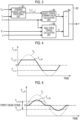
- the reaction force torque command value calculation unit 52 includes a steering torque limiting processing unit 81, an assist torque command value calculation unit 82, an axial force torque calculation unit 83, and a calculator 84.
- the steering torque limiting processing unit 81 receives the steering torque T h detected through the torque sensor 42 and the value of the current limit flag F lim set by the current limiting processing unit 66.
- the steering torque limiting processing unit 81 executes a steering torque limiting process according to the value of the current limit flag F lim .
- the steering torque limiting process is a process of limiting the steering torque T h to limit the output of the turning motor 31.
- the steering torque limiting processing unit 81 does not execute the steering torque limiting process in a case where the value of the current limit flag F lim is "0". That is, the steering torque T h detected through the torque sensor 42 is used as it is for controlling the turning motor 31.
- the steering torque limiting processing unit 81 executes the steering torque limiting process in a case where the current of the turning motor 31 is limited, that is, in a case where the value of the current limit flag F lim is any one of "1" to "4".
- the steering torque limiting processing unit 81 generates a limit steering torque T h_lim by limiting a value of the steering torque T h through the execution of the steering torque limiting process.
- the steering torque limiting processing unit 81 switches a method of limiting the value of the steering torque T h according to the value of the current limit flag F lim .
- the assist torque command value calculation unit 82 receives the steering torque T h from the steering torque limiting processing unit 81 or the limit steering torque T h_lim . Additionally, the assist torque command value calculation unit 82 receives the vehicle speed V detected by the vehicle speed sensor 41. The assist torque command value calculation unit 82 calculates an assist torque command value T1 based on the steering torque T h or the limit steering torque T h_lim , and the vehicle speed V.
- the assist torque command value T1 corresponds to a target value of an assist torque in a case where the steering device 2 is an electric power steering device.
- the assist torque is a force for assisting in steering of the steering wheel 5.
- the assist torque command value T1 is a torque in the same direction as the steering direction of the steering wheel 5. An absolute value of the assist torque command value T1 increases as the absolute value of the steering torque T h increases and the vehicle speed V decreases.
- the axial force torque calculation unit 83 receives the target pinion angle ⁇ p * calculated by the target pinion angle calculation unit 62, the value of the current I b of the turning motor 31 detected through the current sensor 65, and the vehicle speed V detected through the vehicle speed sensor 41.
- the axial force torque calculation unit 83 calculates an axial force acting on the turning shaft 22 based on the target pinion angle ⁇ p *, the value of the current I b of the turning motor 31, and the vehicle speed V.
- the axial force torque calculation unit 83 calculates an axial force torque T2 by converting the calculated axial force into a torque with respect to the steering shaft 11.
- the axial force torque calculation unit 83 may calculate the axial force acting on the turning shaft 22 based on solely any one of the target pinion angle ⁇ p * and the value of the current I b of the turning motor 31.
- the axial force torque calculation unit 83 may receive the pinion angle ⁇ p or the steering angle ⁇ s instead of the target pinion angle ⁇ p *.
- the calculator 84 receives the assist torque command value T1 calculated by the assist torque command value calculation unit 82 and the axial force torque T2 calculated by the axial force torque calculation unit 83.
- the calculator 84 calculates the reaction force torque command value T* by subtracting the axial force torque T2 from the assist torque command value T1.
- the steering torque limiting processing unit 81 can execute first to third limiting processes for the steering torque T h .
- the first to third limiting processes are processes with different limit modes for the steering torque T h .
- the steering torque limiting processing unit 81 executes any one of the first to third limiting process according to the value of the current limit flag F lim .
- the steering torque limiting processing unit 81 executes the first limiting process in a case where the value of the current limit flag F lim is "1" or "4".
- the steering torque limiting processing unit 81 executes the second limiting process in a case where the value of the current limit flag F lim is "2".
- the steering torque limiting processing unit 81 executes a third limiting process in a case where the value of the current limit flag F lim is "3".
- the first limiting process is a process of limiting a change range of the value of the steering torque T h .
- the change range of the value of the steering torque T h is, for example, a range between a first upper limit T h_UL1 and a first lower limit T h_LL1 .
- the first upper limit T h_UL1 is a positive value
- the first lower limit T h_LL1 is a negative value.
- the first upper limit T h_UL1 and the first lower limit T h_LL1 are limit values for the value of the steering torque T h , and are stored in the memory.
- the value of the steering torque T h changes in a sine wave shape.
- the steering torque limiting processing unit 81 compares the value of the steering torque T h with the first upper limit T h_UL1 in a case where the value of the steering torque T h is a positive value.
- the steering torque limiting processing unit 81 limits the value of the steering torque T h to the first upper limit T h_UL1 in a case where the value of the steering torque T h exceeds the first upper limit T h_UL1 .
- the steering torque T h after being limited to the first upper limit T h_UL1 is the limit steering torque T h_lim .
- the steering torque limiting processing unit 81 compares the value of the steering torque T h with the first lower limit T h_LL1 in a case where the value of the steering torque T h is a negative value. In a case where the value of the steering torque T h falls below the first lower limit T h_LL1 , the steering torque limiting processing unit 81 limits the value of the steering torque T h to the first lower limit T h_LL1 .
- the steering torque T h after being limited to the first lower limit T h_LL1 is the limit steering torque T h_lim .
- the steering torque limiting processing unit 81 sets the value of the steering torque T h detected through the torque sensor 42 as it is as a value of the limit steering torque T h_lim .
- the assist torque command value calculation unit 82 calculates the assist torque command value T1 by using the limit steering torque T h_lim obtained through the first limiting process. However, the absolute value of the assist torque command value T1 is smaller than the assist torque command value T1 calculated using the steering torque T h by an amount by which the value of the steering torque T h is limited. As the absolute value of the assist torque command value T1 decreases, the reaction force torque command value T* calculated by the calculator 84, and thus the steering reaction force increases.
- the driver of the vehicle can be given a steering feel as if the steering wheel 5 has become heavier, as a response through the steering wheel 5.
- a weight of the steering wheel 5 is, in a case where the steering device 2 is an electric power steering device that applies an assist force to the steering wheel 5, the same as the weight of the steering wheel 5 when no assist force is applied to the steering wheel 5. The driver of the vehicle can recognize that the first event B1 or the fourth event B4 has occurred by feeling the steering reaction force through the steering wheel 5 as a response.
- the second limiting process is a process of setting a first dead zone for the steering torque T h and limiting the value of the steering torque T h to "0" in a case where the value of the steering torque T h reaches a value within the first dead zone.
- the first dead zone is a certain range of the value of the steering torque T h including "0".
- the first dead zone is a range between a second upper limit T h_UL2 and a second lower limit T h_LL2 .
- the second upper limit T h_UL2 is a positive value
- the second lower limit T h_LL2 is a negative value.
- the second upper limit T h_UL2 and the second lower limit T h_LL2 are limit values for the value of the steering torque T h , and are stored in the memory.
- the value of the steering torque T h changes in a sine wave shape.
- the steering torque limiting processing unit 81 sets the value of the limit steering torque T h_lim that is the output to "0" until the value of the steering torque T h exceeds the second upper limit T h_UL2 .
- the steering torque limiting processing unit 81 sets the value of the limit steering torque T h_lim according to the value of the steering torque T h after the value of the steering torque T h exceeds the second upper limit T h_UL2 .
- the value of the limit steering torque T h_lim does not follow the value of the original steering torque T h that changes in a sine wave shape.
- the value of the limit steering torque T h_lim is smaller than the value of the original steering torque T h .
- the steering torque limiting processing unit 81 sets the value of the limit steering torque T h_lim that is the output to "0" until the value of the steering torque T h falls below the second lower limit T h_LL2 .
- the steering torque limiting processing unit 81 sets the value of the limit steering torque T h_lim according to the value of the steering torque T h after the value of the steering torque T h falls below the second lower limit T h_LL2 .
- the value of the limit steering torque T h_lim does not follow the value of the original steering torque T h that changes in a sine wave shape.
- the value of the limit steering torque T h_lim is smaller than the value of the original steering torque T h .
- the steering reaction force is rapidly increased or decreased with the steering of the steering wheel 5. Therefore, as a response through the steering wheel 5, the driver of the vehicle can be given a steering feel with a sense of resistance. The driver of the vehicle can recognize that the second event B2 has occurred by feeling the steering reaction force through the steering wheel 5 as a response.
- the third limiting process is a process of setting a second dead zone specified by a limit value T h_LV with respect to the absolute value of the steering torque T h , and gradually increasing the second dead zone by gradually decreasing the limit value T h_LV after the absolute value of the steering torque T h reaches a value within the second dead zone, thereby limiting the absolute value of the steering torque T h to the limit value T h_LV .
- the limit value T h_LV is a value greater than "0" and is a boundary value of the second dead zone. That is, the second dead zone is a range of the absolute value of the steering torque T h equal to or more than the limit value T h_LV .
- the limit value T h_LV is set to the same value as the absolute value of the steering torque T h when an end hit occurs, for example.
- the limit value T h_LV is stored in the memory.
- the absolute value of the steering torque T h changes as follows. That is, the absolute value of the steering torque T h gradually increases with the steering of the steering wheel 5, and eventually reaches a predetermined value (time T1).
- the predetermined value is equal to the limit value T h_LV .
- the absolute value of the steering torque T h is maintained at the predetermined value.
- the steering torque limiting processing unit 81 sets the absolute value of the steering torque T h as an absolute value of the limit steering torque T h_lim until the absolute value of the steering torque T h reaches the limit value T h_LV .
- the steering torque limiting processing unit 81 gradually expands a range of the dead zone after the absolute value of the steering torque T h reaches the limit value T h_LV . That is, as shown by an arrow AD in FIG. 6 , the steering torque limiting processing unit 81 gradually decreases the limit value T h_LV .
- the steering torque limiting processing unit 81 compares the absolute value of the steering torque T h with the limit value T h_LV .
- the steering torque limiting processing unit 81 limits the absolute value of the steering torque T h to the limit value T h_LV in a case where the absolute value of the steering torque T h exceeds the limit value T h_LV .
- the absolute value of the steering torque T h after being limited to the limit value T h_LV is the absolute value of the limit steering torque T h_lim . Since the limit value T h_LV gradually decreases, the absolute value of the steering torque T h , and thus the absolute value of the limit steering torque T h_lim gradually decrease.
- the steering reaction force gradually increases with the steering of the steering wheel 5. Therefore, as a response through the steering wheel 5, the driver of the vehicle can be given a steering feel as if the steering wheel 5 is gradually pushed back, or a steering feel with a sense of collision. The driver of the vehicle can recognize that the third event B3 has occurred by feeling the steering reaction force through the steering wheel 5 as a response.
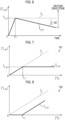
- the steering torque limiting processing unit 81 may execute the following process as the first limiting process. That is, the steering torque limiting processing unit 81 calculates the limit steering torque T h_lim by using a first conversion map M1 or a second conversion map M2 instead of the first upper limit T h_UL1 and the first lower limit T h_LL1 .
- the first conversion map M1 or the second conversion map M2 is stored in the memory.
- the first conversion map M1 is a two-dimensional map that specifies a relationship between the absolute value of the steering torque T h and the absolute value of the limit steering torque T h_lim .
- the first conversion map M1 has the following characteristics. That is, in a case where the absolute value of the steering torque T h gradually increases, after the absolute value of the steering torque T h reaches a first steering torque threshold T h_1 , the absolute value of the limit steering torque T h_lim is maintained at a set value T h_lim1 regardless of the absolute value of the steering torque T h .
- the set value T h_lim1 is a certain value smaller than the absolute value of the steering torque T h .
- the first steering torque threshold T h_1 is, for example, a value near "0".
- the steering reaction force becomes greater than the original steering reaction force according to the steering torque T h . Therefore, the driver of the vehicle can be given a steering feel as if the steering wheel 5 has become heavier, as a response through the steering wheel 5.
- the steering device 2 is assumed to be an electric power steering device, the same steering feel as when no assist force is applied to the steering wheel 5 can be reproduced.
- the second conversion map M2 is a two-dimensional map that specifies a relationship between the absolute value of the steering torque T h and the absolute value of the limit steering torque T h_lim .
- the second conversion map M2 has the following characteristics. That is, in a case where the absolute value of the steering torque T h gradually increases, the absolute value of the limit steering torque T h_lim is maintained at "0" until the absolute value of the steering torque T h reaches a second steering torque threshold T h_2 . After the absolute value of the steering torque T h reaches the second steering torque threshold T h_2 , the absolute value of the limit steering torque T h_lim gradually increases. However, the absolute value of the limit steering torque T h_lim is smaller than the absolute value of the steering torque T h .
- the second steering torque threshold T h_2 is, for example, a value near "0".
- the steering reaction force decreases as the absolute value of the steering torque T h increases. Therefore, as a response through the steering wheel 5, the driver of the vehicle can be given a steering feel as if the steering wheel 5 becomes gradually lighter.
- the first embodiment has the following effects.
- the steering control device 1 includes the steering torque limiting processing unit 81.
- the steering torque limiting processing unit 81 limits the value of the steering torque T h . Since the reaction force torque command value T* is increased by the amount by which the value of the steering torque T h is limited, the steering reaction force applied to the steering wheel 5 also increases. Therefore, the driver of the vehicle can recognize that the output of the turning motor 31 is limited by feeling the steering reaction force through the steering wheel 5 as a response. Therefore, the driver of the vehicle can be appropriately informed that the output of the turning motor 31 is limited.
- the value of the steering torque T h is limited.
- the steering device 2 is assumed to be an electric power steering device, the same steering feel as when no assist force is applied to the steering wheel 5 can be reproduced. Even in a case where a steering speed of the steering wheel 5 is slow, the reaction force torque command value T* and thus the steering reaction force is increased by the amount by which the value of the steering torque T h is limited. Therefore, the driver of the vehicle can be reliably informed that the output of the turning motor 31 is limited.
- the steering torque limiting processing unit 81 executes the limiting process of limiting the steering torque T h .
- the limiting process includes a plurality of limiting processes with different limit modes for the steering torque T h .
- the steering torque limiting processing unit 81 switches the limiting process to be executed according to a content of the event in which the output of the turning motor 31 is limited.
- any one of the limiting processes with different limit modes for the steering torque T h is executed according to the content of the event in which the output of the turning motor 31 is limited. Therefore, the value of the steering torque T h can be appropriately limited according to the content of the event in which the output of the turning motor 31 is limited.
- the limiting process for the steering torque T h includes, for example, the first limiting process, the second limiting process, and the third limiting process.
- any one of the first to third limiting processes is executed according to the content of the event in which the output of the turning motor 31 is limited. Therefore, the value of the steering torque T h can be appropriately limited according to the content of the event in which the output of the turning motor 31 is limited.
- the limit modes for the value of the steering torque T h of the first to third limiting processes are different, the driver of the vehicle can be given different steering feels according to the content of the event as a response through the steering wheel 5. The driver of the vehicle can recognize the content of the event in which the output of the turning motor 31 is limited by feeling the steering reaction force through the steering wheel 5 as a response.
- the steering torque limiting processing unit 81 executes the first limiting process.
- the driver of the vehicle can be given a steering feel as if the steering wheel 5 has become heavier, as a response through the steering wheel 5.
- the driver of the vehicle can recognize that the first event B1 or the fourth event B4 has occurred by feeling the steering reaction force through the steering wheel 5 as a response.
- the steering torque limiting processing unit 81 executes the second limiting process in a case where the second event occurs.
- the driver of the vehicle can be given a steering feel with a sense of resistance, as a response through the steering wheel 5.
- the driver of the vehicle can recognize that the second event B2 has occurred by feeling the steering reaction force through the steering wheel 5 as a response.
- the steering torque limiting processing unit 81 executes the third limiting process in a case where the third event B3 occurs.
- the driver of the vehicle can be given a steering feel as if the steering wheel 5 is gradually pushed back, or a steering feel with a sense of collision.
- the driver of the vehicle can recognize that the third event B3 has occurred by feeling the steering reaction force through the steering wheel 5 as a response.
- the present embodiment basically has the same configuration as the first embodiment shown in FIGS. 1 and 2 .
- the present embodiment is different from the first embodiment in that the configuration of the reaction force torque command value calculation unit 52 is different. Therefore, the same members and configurations as those of the first embodiment are denoted by the same reference numerals, and a detailed description thereof will be omitted.
- the reaction force torque command value calculation unit 52 has a command value limiting processing unit 85 instead of the previous steering torque limiting processing unit 81.
- the command value limiting processing unit 85 receives the assist torque command value T1 calculated by the assist torque command value calculation unit 82 and the value of the current limit flag F lim set by the current limiting processing unit 66.
- the current limit flag F lim includes information indicating a limiting ratio LP of the current supplied to the turning motor 31.
- the limiting ratio LP is an amount of current actually supplied to the turning motor 31 among the original current supplied from the energization controller 64 to the turning motor 31.
- the limiting ratio LP is, for example, a value in a range of "0.1" or more and “1.0” or less, and is set in increments of "0.1". "0.1" corresponds to "10%”.
- the command value limiting processing unit 85 executes a command value limiting process according to the limiting ratio LP included in the current limit flag F lim .
- the command value limiting process is a process of limiting the assist torque command value T1 in order to limit the output of the turning motor 31.
- the command value limiting processing unit 85 does not execute the command value limiting processing in a case where the value of the current limit flag F lim is "0". That is, the assist torque command value T1 calculated by the assist torque command value calculation unit 82 is used for controlling the turning motor 31 as it is.
- the command value limiting processing unit 85 executes the command value limiting process in a case where the value of the current limit flag F lim is any one of "1" to "4".
- the command value limiting processing unit 85 generates a limit assist torque command value T1 _lim by limiting the assist torque command value T1 through the execution of the command value limiting process.
- the command value limiting processing unit 85 limits the assist torque command value T1 by the same ratio as the limiting ratio LP, for example. For example, in a case where the limiting ratio LP is "0.9", the limit assist torque command value T1 _lim is 90% of the original assist torque command value T1 calculated by the assist torque command value calculation unit 82. To the extent to which an absolute value of the limit assist torque command value T1 _lim is smaller than the absolute value of the original assist torque command value T1, the reaction force torque command value T* calculated by the calculator 84 and thus the steering reaction force increases.
- the steering reaction force becomes greater than the steering reaction force under normal conditions in which the command value limiting process is not executed. Therefore, as a response through the steering wheel 5, the driver of the vehicle can be given a steering feel as if the steering wheel 5 is heavier than normal conditions. The driver of the vehicle can recognize that any one of the first to fourth events B1 to B4 has occurred by feeling the steering reaction force through the steering wheel 5 as a response.
- the second embodiment has the following effects.
- the steering control device 1 includes the command value limiting processing unit 85.
- the command value limiting processing unit 85 limits the assist torque command value T1. Since the reaction force torque command value T* is increased by an amount by which the assist torque command value T1 is limited, the steering reaction force applied to the steering wheel 5 also increases. Therefore, the driver of the vehicle can recognize that the output of the turning motor 31 is limited by feeling the steering reaction force through the steering wheel 5 as a response. Therefore, the driver of the vehicle can be appropriately informed that the output of the turning motor 31 is limited.
- the output of the turning motor 31 is limited by limiting the current I b supplied to the turning motor 31 by a predetermined limiting ratio LP.
- the command value limiting processing unit 85 limits the assist torque command value T1 by the same ratio as the limiting ratio LP. Therefore, the steering reaction force increases according to a degree to which the output of the turning motor 31 is limited. Therefore, the driver of the vehicle can recognize that the output of the turning motor 31 is limited by feeling the steering reaction force through the steering wheel 5 as a response.
- the assist torque command value T1 is limited. Therefore, even in a case where the steering speed of the steering wheel 5 is slow, the reaction force torque command value T* and thus the steering reaction force is increased by the amount by which the assist torque command value T1 is limited. Therefore, the driver of the vehicle can be reliably informed that the output of the turning motor 31 is limited.
- the steering torque limiting processing unit 81 may not switch the method of limiting the value of the steering torque T h between the first to third limiting processes according to the value of the current limit flag F lim .
- the steering torque limiting processing unit 81 gradually decreases the absolute value of the steering torque T h regardless of whether the value of the current limit flag F lim is any of "1" to "4", for example.
- An absolute value of the gradually decreasing steering torque T h is set as the absolute value of the limit steering torque T h_lim .
- the reaction force torque command value T* gradually increases.
- the driver of the vehicle can be given a steering feel as if the steering wheel 5 is gradually getting heavier.
- the driver of the vehicle can recognize that any one of the first to fourth events B1 to B4 has occurred by feeling the steering reaction force through the steering wheel 5 as a response.
- the command value limiting processing unit 85 may calculate the limit assist torque command value T1 _lim by using a third conversion map M3 instead of the limiting ratio LP.
- the third conversion map M3 is stored in the memory.
- the current limit flag F lim may not include the information indicating the limiting ratio LP of the current supplied to the turning motor 31.
- the third conversion map M3 is a two-dimensional map that specifies a relationship between the absolute value of the assist torque command value T1 and the absolute value of the limit assist torque command value T1 _lim .
- the third conversion map M3 has the following characteristics. That is, in a case where the absolute value of the assist torque command value T1 gradually increases, after the absolute value of the assist torque command value T1 reaches a command value threshold T1 th , the absolute value of the limit assist torque command value T1 _lim is maintained at a set value T1_ lim1 regardless of the absolute value of the assist torque command value T1. However, the set value T1 _lim1 is a certain value smaller than the absolute value of the assist torque command value T1.
- the command value threshold T1 th is, for example, a value near "0".
- the driver of the vehicle can be given a steering feel as if the steering wheel 5 has become heavier, as a response through the steering wheel 5.
- the driver of the vehicle can recognize that any one of the first to fourth events B1 to B4 has occurred by feeling the steering reaction force through the steering wheel 5 as a response.
- the limit assist torque command value T1 _lim can be easily obtained from the assist torque command value T1.
- Obtaining the limit assist torque command value T1 _lim by using the third conversion map M3 is to limit the assist torque command value T1 used to control the reaction force motor 12.
- the assist torque command value calculation unit 82 has a function of the command value limiting processing unit 85.
- the assist torque command value calculation unit 82 receives the value of the steering torque T h detected through the torque sensor 42 and the value of the current limit flag F lim set by the current limiting processing unit 66. Note that the current limit flag F lim may not include the information indicating the limiting ratio LP of the current supplied to the turning motor 31.
- the assist torque command value calculation unit 82 does not execute the command value limiting process in a case where the value of the current limit flag F lim is "0". That is, the assist torque command value T1 calculated by the assist torque command value calculation unit 82 is used for controlling the turning motor 31 as it is.
- the command value limiting processing unit 85 executes the command value limiting process in a case where the value of the current limit flag F lim is any one of "1" to "4".
- the command value limiting processing unit 85 generates the limit assist torque command value T1 _lim by limiting the assist torque command value T1 through the execution of the command value limiting process.
- the assist torque command value calculation unit 82 calculates the limit assist torque command value T1 _lim by using, for example, a fourth conversion map M4.
- the fourth conversion map M4 is stored in the memory.
- the fourth conversion map M4 is a two-dimensional map that specifies a relationship between the absolute value of the steering torque T h and the absolute value of the limit assist torque command value T1 _lim .
- the fourth conversion map M4 has the following characteristics. That is, in a case where the absolute value of the steering torque T h gradually increases, after the absolute value of the steering torque T h reaches a third steering torque threshold T h_3 , the absolute value of the limit assist torque command value T1 _lim gradually decreases as the absolute value of the steering torque T h increases.
- an inclination which is a ratio of a change in the absolute value of the limit assist torque command value T1 _lim with respect to the absolute value of the steering torque T h , gradually decreases.
- the absolute value of the limit assist torque command value T1 _lim is the same value as the absolute value of the assist torque command value T1 until the absolute value of the steering torque T h reaches the third steering torque threshold T h_3 .
- the absolute value of the limit assist torque command value T1 _lim is smaller than the absolute value of the assist torque command value T1 after the absolute value of the steering torque T h reaches the third steering torque threshold T h_3 .
- the third steering torque threshold T h_3 is, for example, a value near "0".
- the steering reaction force becomes greater than the original steering reaction force according to the steering torque T h .
- the steering reaction force gradually increases as the absolute value of the steering torque T h increases. Therefore, as a response through the steering wheel 5, the driver of the vehicle can be given a steering feel as if the steering wheel 5 is gradually getting heavier. The driver of the vehicle can recognize that any one of the first to fourth events B1 to B4 has occurred by feeling the steering reaction force through the steering wheel 5 as a response.
- the limit assist torque command value T1_ lim can be easily obtained from the absolute value of the steering torque T h .
- Obtaining the limit assist torque command value T1 _lim by using the fourth conversion map M4 is to limit the assist torque command value T1 used to control the reaction force motor 12.
Landscapes
- Engineering & Computer Science (AREA)
- Chemical & Material Sciences (AREA)
- Combustion & Propulsion (AREA)
- Transportation (AREA)
- Mechanical Engineering (AREA)
- Steering Control In Accordance With Driving Conditions (AREA)
- Power Steering Mechanism (AREA)
Abstract
An assist torque command value calculation unit (82) of a steering control device (1) is configured to calculate an assist torque command value based on a first state variable reflecting a steering state of a steering wheel (5). An axial force torque calculation unit (83) is configured to calculate an axial force torque based on a second state variable reflecting a turning state of turning wheels (6). A calculator (84) is configured to calculate a reaction force torque command value by subtracting the axial force torque from the assist torque command value. A limiting processing unit is configured to limit the first state variable or the assist torque command value in a case where an event in which an output of the turning motor (31) is limited occurs.
Description
- The present invention relates to a steering control device.
- In the related art, a so-called steer-by-wire type steering device is known in which power transmission between a steering wheel and turning wheels is separated. The steering device includes a reaction force motor that is a source of a steering reaction force applied to a steering shaft, and a turning motor that is a source of a turning force to turn the turning wheels. When a vehicle travels, a control device of the steering device generates the steering reaction force through the reaction force motor and turns the turning wheels through the turning motor.
- For example, a control device of
Japanese Unexamined Patent Application Publication No. 2020-83059 JP 2020-83059 A - In the output limiting process, the control device limits the output of the turning motor, for example, by decreasing a current limit value as a steering speed of the steering wheel increases. The current limit value is an upper limit of a current supplied to the turning motor. In the reaction force increasing process, the control device increases the steering reaction force, for example, by increasing a damping component of the steering reaction force compared to a case where the output limiting process is not executed. The damping component of the steering reaction force increases as the steering speed increases.
- In a case where the reaction force is increased by increasing the damping component of the steering reaction force in the reaction force increasing process executed in synchronization with the output limiting process, as in the control device of
JP 2020-83059 A - A first aspect of the invention relates to a steering control device configured to control electric power supply to a reaction force motor configured to generate a steering reaction force applied to a steering wheel in which power transmission to turning wheels of a vehicle is separated, based on a reaction force torque command value calculated according to a steering state of the steering wheel, and control electric power supply to a turning motor configured to generate a turning force for turning the turning wheels, based on a turning torque command value calculated according to the steering state of the steering wheel. The steering control device includes an assist torque command value calculation unit, an axial force torque calculation unit, a calculator, and a limiting processing unit. The assist torque command value calculation unit is configured to calculate an assist torque command value that is a torque in the same direction as a steering direction of the steering wheel based on a first state variable reflecting the steering state of the steering wheel. The axial force torque calculation unit is configured to calculate an axial force acting on a turning shaft configured to turn the turning wheels based on a second state variable reflecting a turning state of the turning wheels, and calculate an axial force torque by converting the calculated axial force into a torque with respect to the steering wheel. The calculator is configured to calculate the reaction force torque command value by subtracting the axial force torque from the assist torque command value. The limiting processing unit is configured to limit the first state variable or the assist torque command value in a case where an event in which an output of the turning motor is limited occurs.
- With this configuration, in a case where the event in which the output of the turning motor is limited occurs, the first state variable or the assist torque command value is limited. Since the reaction force torque command value is increased by an amount by which the first state variable or the assist torque command value is limited, the steering reaction force applied to the steering wheel also increases. Therefore, a driver of the vehicle can recognize that the output of the turning motor is limited by feeling the steering reaction force through the steering wheel as a response. Therefore, the driver of the vehicle can be appropriately informed that the output of the turning motor is limited.
- In the steering control device, the limiting processing unit may be configured to execute a limiting process of limiting the first state variable in a case where the event occurs. The limiting process may include a plurality of limiting processes having different limit modes for the first state variable. The limiting processing unit may be configured to switch the limiting process to be executed according to a content of the event.
- With this configuration, any one of the limiting processes with different limit modes for the first state variable is executed according to the content of the event in which the output of the turning motor is limited. Therefore, a value of the first state variable can be appropriately limited according to the content of the event in which the output of the turning motor is limited.
- In the steering control device, the limiting process may include a first limiting process, a second limiting process, and a third limiting process. The first limiting process is a process of limiting a change range of the first state variable based on a limit value determined for the first state variable or a process of limiting a value of the first state variable based on a conversion map that specifies a relationship between the first state variable and the first state variable after the limiting. The second limiting process is a process of setting, with respect to the first state variable, a first dead zone that is a range of the value of the first state variable including zero, and limiting the value of the first state variable to zero in a case where the value of the first state variable reaches a value within the first dead zone. The third limiting process is a process of setting, with respect to an absolute value of the first state variable, a second dead zone that is a range of the absolute value of the first state variable specified by a boundary value greater than zero, and gradually increasing the second dead zone by gradually decreasing the boundary value after the absolute value of the first state variable reaches a value within the second dead zone such that an absolute value of the first state variable limited to the boundary value.
- With this configuration, any one of the first to third limiting processes is executed according to the content of the event in which the output of the turning motor is limited. Therefore, a value of the first state variable can be appropriately limited according to the content of the event in which the output of the turning motor is limited. Additionally, since the limit modes for the value of the first state variable of the first to third limiting processes are different, the driver of the vehicle can be given different steering feels according to the content of the event in which the output of the turning motor is limited, as a response through the steering wheel. Therefore, the driver of the vehicle can recognize the content of the event in which the output of the turning motor is limited by feeling the steering reaction force through the steering wheel as a response.
- In the steering control device, the event may include a first event in which a temperature of the turning motor excessively rises, a second event in which a voltage input to the steering control device decreases, a third event in which a high load is continuously applied to the turning motor, and a fourth event in which, in a case where the turning motor has two systems of winding groups, electric power supply to any one of the two systems of winding groups is difficult. In this case, the limiting processing unit may be configured to execute the first limiting process in a case where the first event or the fourth event occurs, execute the second limiting process in a case where the second event occurs, and execute the third limiting process in a case where the third event occurs.
- With this configuration, in a case where the first event or the fourth event occurs, the first limiting process is executed. By executing the first limiting process, the driver of the vehicle can be given a steering feel as if the steering wheel has become heavier, as a response through the steering wheel. The driver of the vehicle can recognize that the first event or the fourth event has occurred by feeling the steering reaction force through the steering wheel as a response.
- In a case where the second event occurs, the second limiting process is executed. By executing the second limiting process, the driver of the vehicle can be given a steering feel with a sense of resistance, as a response through the steering wheel. The driver of the vehicle can recognize that the second event has occurred by feeling the steering reaction force through the steering wheel as a response.
- In a case where the third event occurs, the third limiting process is executed. By executing the third limiting process, as a response through the steering wheel, the driver of the vehicle can be given a steering feel as if the steering wheel is gradually pushed back, or a steering feel with a sense of collision. The driver of the vehicle can recognize that the third event has occurred by feeling the steering reaction force through the steering wheel as a response.
- In the steering control device, the turning motor may be configured such that, in a case where the event occurs, the output of the turning motor is limited by limiting a current supplied to the turning motor by a predetermined limiting ratio. In this case, the limiting processing unit may be configured to limit the assist torque command value by the same ratio as the predetermined limiting ratio in a case where the event occurs.
- With this configuration, in a case where an event occurs in which the output of the turning motor is limited, the assist torque command value is limited by the same ratio as the limiting ratio of the current of the turning motor. Therefore, the steering reaction force increases according to a degree to which the output of the turning motor is limited. Therefore, the driver of the vehicle can recognize that the output of the turning motor is limited by feeling the steering reaction force through the steering wheel as a response.
- In the steering control device, the limiting processing unit may be configured to, in a case where the event occurs, limit the assist torque command value based on a conversion map that specifies a relationship between the assist torque command value and the assist torque command value after the limiting.
- With this configuration, by using the conversion map, the assist torque command value after the limiting can be easily obtained from the assist torque command value. Obtaining the assist torque command value after the limiting by using the conversion map is to limit the assist torque command value used to control the reaction force motor.
- In the steering control device, the limiting processing unit may be configured to, in a case where the event occurs, limit the assist torque command value based on a conversion map that specifies a relationship between the first state variable and the assist torque command value after the limiting.
- With this configuration, by using the conversion map, the assist torque command value after the limiting can be easily obtained from the first state variable. Obtaining the assist torque command value after the limiting by using the conversion map is to limit the assist torque command value used to control the reaction force motor.
- In the steering control device, the first state variable may be a steering torque applied to the steering wheel. The second state variable may be at least one of a current of the turning motor and a target rotation angle of a pinion shaft that is rotated in conjunction with the turning shaft.
- As in the configuration, the steering torque is an example of the first state variable reflecting the steering state of the steering wheel. In addition, the current of the turning motor or the target rotation angle of the pinion shaft that is rotated in conjunction with the turning shaft is an example of the second state variable reflecting the turning state of the turning wheels.
- With the steering control device according to the invention, the driver of the vehicle can be appropriately informed that the output of the turning motor is limited.
- Features, advantages, and technical and industrial significance of exemplary embodiments of the invention will be described below with reference to the accompanying drawings, in which like signs denote like elements, and wherein:
-
FIG. 1 is a configuration diagram of a steering device in which a first embodiment of a steering control device is mounted; -
FIG. 2 is a block diagram of a reaction force control device and a turning control device according to the first embodiment; -
FIG. 3 is a block diagram of a reaction force torque command value calculation unit according to the first embodiment; -
FIG. 4 is a graph for describing a first limiting process according to the first embodiment; -
FIG. 5 is a graph for describing a second limiting process according to the first embodiment; -
FIG. 6 is a graph for describing a third limiting process according to the first embodiment; -
FIG. 7 is a graph showing a first conversion map according to a modification example of the first embodiment; -
FIG. 8 is a graph showing a second conversion map according to a modification example of the first embodiment; -
FIG. 9 is a block diagram of a reaction force torque command value calculation unit according to a second embodiment; -
FIG. 10 is a graph showing a third conversion map according to a modification example of another embodiment; and -
FIG. 11 is a graph showing a fourth conversion map according to a modification example of another embodiment. - Hereinafter, a first embodiment of a steering control device will be described.
- As shown in
FIG. 1 , a control target of thesteering control device 1 is a steer-by-wiretype steering device 2. Thesteering device 2 includes a steering mechanism 3 and a turning mechanism 4. The steering mechanism 3 is a mechanism part that is steered by a driver through asteering wheel 5. The turning mechanism 4 is a mechanism part that turns turningwheels 6 of a vehicle in response to steering of thesteering wheel 5. Thesteering control device 1 includes a reactionforce control device 1A and aturning control device 1B. A control target of the reactionforce control device 1A is the steering mechanism 3. The reactionforce control device 1A performs reaction force control. The reactionforce control device 1A corresponds to a reaction force controller. A control target of the turningcontrol device 1B is the turning mechanism 4. The turningcontrol device 1B performs turning control. The turningcontrol device 1B corresponds to a turning controller. - The steering mechanism 3 includes a steering
shaft 11, areaction force motor 12, and areduction gear 13. Thesteering wheel 5 is integrally rotatably connected to the steeringshaft 11. Thereaction force motor 12 is a source of a steering reaction force applied to the steeringshaft 11. The steering reaction force is a force in a direction opposite to a steering direction of thesteering wheel 5. Thereaction force motor 12 is, for example, a three-phase brushless motor. Thereduction gear 13 reduces rotation of thereaction force motor 12 and transmits the reduced rotation to the steeringshaft 11. - The turning mechanism 4 includes a
pinion shaft 21, a turningshaft 22, and ahousing 23. Thehousing 23 rotatably supports thepinion shaft 21. Thehousing 23 accommodates the turningshaft 22 such that the turningshaft 22 can reciprocate. Transmission of power between the turningshaft 22 and thesteering wheel 5 is separated. Thepinion shaft 21 is provided to cross the turningshaft 22.Pinion teeth 21a of thepinion shaft 21 mesh withrack teeth 22a of the turningshaft 22.Tie rods 25 are connected to both ends of the turningshaft 22 through rack ends 24 formed of ball joints. A tip end of thetie rod 25 is connected to a knuckle (not shown) to which theturning wheel 6 is assembled. - The turning mechanism 4 includes a turning
motor 31, atransmission mechanism 32, and aconversion mechanism 33. The turningmotor 31 is a source of a turning force applied to the turningshaft 22. The turning force is a force for turning theturning wheels 6. The turningmotor 31 is, for example, a three-phase brushless motor. Thetransmission mechanism 32 is, for example, a belt transmission mechanism. Thetransmission mechanism 32 transmits rotation of the turningmotor 31 to theconversion mechanism 33. Theconversion mechanism 33 is, for example, a ball screw mechanism. Theconversion mechanism 33 converts the rotation transmitted through thetransmission mechanism 32 into an axial movement of the turningshaft 22. - The axial movement of the turning
shaft 22 changes a turning angle θw of theturning wheel 6. Thepinion teeth 21a of thepinion shaft 21 mesh with therack teeth 22a of the turningshaft 22. Therefore, thepinion shaft 21 rotates in conjunction with the movement of the turningshaft 22. Thepinion shaft 21 is a shaft or a rotating body that rotates in conjunction with a turning operation of the turningwheels 6. - The reaction
force control device 1A controls an operation of thereaction force motor 12. The reactionforce control device 1A includes a processing circuit including any one of the following three configurations A1, A2, A3. A1. One or more processors operating according to a computer program that is software. The processor includes a central processing unit (CPU) and a memory. - A2. One or more dedicated hardware circuits, such as an application-specific integrated circuit (ASIC), that executes at least a part of various processes. The ASIC includes a CPU and a memory.
- A3. A hardware circuit in which the configurations A1 and A2 are combined. The memory is a computer-readable medium and stores a program that describes processing or an instruction for a computer. In the present embodiment, the computer is a CPU. The memory includes a random-access memory (RAM) and a read-only memory (ROM). The CPU performs various controls by executing a program stored in the memory at a predetermined calculation cycle.
- The reaction
force control device 1A receives a detection result of an in-vehicle sensor. The sensor includes a vehicle speed sensor 41, atorque sensor 42, and arotation angle sensor 43. The vehicle speed sensor 41 detects a vehicle speed V. The vehicle speed V is a state variable reflecting a traveling state of the vehicle. Thetorque sensor 42 is provided on the steeringshaft 11. Thetorque sensor 42 is located on asteering wheel 5 side with respect to a portion of steeringshaft 11 to which thereduction gear 13 is connected. Thetorque sensor 42 detects a steering torque Th applied to the steeringshaft 11. The steering torque Th is calculated based on an amount of twist of atorsion bar 42a provided in the steeringshaft 11. The steering torque Th is an example of a first state variable reflecting a steering state of thesteering wheel 5. Therotation angle sensor 43 is provided in thereaction force motor 12. Therotation angle sensor 43 detects a rotation angle θa of thereaction force motor 12. - The steering torque Th and the rotation angle θa of the
reaction force motor 12 are, for example, positive values in a case where thesteering wheel 5 is steered to the right, and are negative values in a case where thesteering wheel 5 is steered to the left. - The reaction
force control device 1A controls the operation of thereaction force motor 12 by using detection results of the vehicle speed sensor 41, thetorque sensor 42, and therotation angle sensor 43. The reactionforce control device 1A controls electric power supply to thereaction force motor 12 such that the steering reaction force according to the steering torque Th is generated in thereaction force motor 12. - The turning
control device 1B controls an operation of the turningmotor 31. The turningcontrol device 1B includes a processing circuit including any one of the three configurations A1, A2, A3 described above, as in the reactionforce control device 1A. - The turning
control device 1B receives a detection result of an in-vehicle sensor. The sensor includes arotation angle sensor 44. Therotation angle sensor 44 is provided in the turningmotor 31. Therotation angle sensor 44 detects a rotation angle θb of the turningmotor 31. The rotation angle θb of the turningmotor 31 is, for example, a positive value in a case where thesteering wheel 5 is steered to the right, and is a negative value in a case where thesteering wheel 5 is steered to the left. - The turning
control device 1B controls the operation of the turningmotor 31 by using the detection result of therotation angle sensor 44. The turningcontrol device 1B controls electric power supply to the turningmotor 31 such that the turningwheels 6 are turned according to the steering state of thesteering wheel 5. - Next, the configuration of the reaction
force control device 1A will be described. As shown inFIG. 2 , the reactionforce control device 1A includes a steeringangle calculation unit 51, a reaction force torque commandvalue calculation unit 52, and anenergization controller 53. - The steering
angle calculation unit 51 calculates a steering angle θs of thesteering wheel 5 based on the rotation angle θa of thereaction force motor 12 detected through therotation angle sensor 43. The reaction force torque commandvalue calculation unit 52 calculates a reaction force torque command value T* based on the steering torque Th and the vehicle speed V. The reaction force torque command value T* is a target value of the steering reaction force to be generated in thereaction force motor 12. The steering reaction force is a torque in a direction opposite to the steering direction of thesteering wheel 5. As an absolute value of the steering torque Th increases and the vehicle speed V decreases, an absolute value of the reaction force torque command value T* further increases. - The
energization controller 53 supplies electric power according to the reaction force torque command value T* to thereaction force motor 12. Specifically, theenergization controller 53 calculates a current command value for thereaction force motor 12 based on the reaction force torque command value T*. Theenergization controller 53 detects a value of a current Ia generated in an electric power supply path through acurrent sensor 54 provided in the electric power supply path for thereaction force motor 12. The value of the current Ia is a value of a current supplied to thereaction force motor 12. Theenergization controller 53 obtains a deviation between the current command value and the value of the current Ia, and controls the electric power supply to thereaction force motor 12 such that the deviation is eliminated. As a result, thereaction force motor 12 generates a torque according to the reaction force torque command value T*. - Next, the configuration of the turning
control device 1B will be described. As shown inFIG. 2 , the turningcontrol device 1B includes a pinionangle calculation unit 61, a target pinionangle calculation unit 62, a pinionangle feedback controller 63, anenergization controller 64, acurrent sensor 65, and a current limitingprocessing unit 66. - The pinion
angle calculation unit 61 calculates a pinion angle θp based on the rotation angle θb of the turningmotor 31 detected through therotation angle sensor 44. The pinion angle θp is a rotation angle of thepinion shaft 21. The turningmotor 31 and thepinion shaft 21 move in conjunction with each other through thetransmission mechanism 32, theconversion mechanism 33, and the turningshaft 22. Therefore, there is a correlation between the rotation angle θb of the turningmotor 31 and the pinion angle θp. The pinion angle θp can be obtained from the rotation angle θb of the turningmotor 31 by using this correlation. Thepinion shaft 21 meshes with the turningshaft 22. Therefore, there is also a correlation between the pinion angle θp and a movement amount of the turningshaft 22. That is, the pinion angle θp is a value reflecting the turning angle θw of theturning wheel 6. - The target pinion
angle calculation unit 62 calculates a target pinion angle θp* based on the steering angle θs calculated by the steeringangle calculation unit 51. The target pinion angle θp* is a target angle of the pinion angle θp. The target pinionangle calculation unit 62 calculates the target pinion angle θp* such that a steering angle ratio set according to product specifications or the like is achieved. The steering angle ratio is a ratio of the turning angle θw to the steering angle θs. - The target pinion
angle calculation unit 62 sets the steering angle ratio according to the traveling state of the vehicle, such as the vehicle speed V, and calculates the target pinion angle θp* according to the set steering angle ratio. The target pinionangle calculation unit 62 calculates the target pinion angle θp* such that the turning angle θw with respect to the steering angle θs increases as the vehicle speed V decreases. The target pinionangle calculation unit 62 calculates the target pinion angle θp* such that the turning angle θw with respect to the steering angle θs decreases as the vehicle speed V increases. The target pinionangle calculation unit 62 calculates a correction angle with respect to the steering angle θs to achieve the steering angle ratio set according to the traveling state of the vehicle, and calculates the target pinion angle θp* according to the steering angle ratio by adding the calculated correction angle to the steering angle θs. The target pinion angle θp* is a target rotation angle of thepinion shaft 21, and is an example of a second state variable reflecting a turning state of the turningwheels 6. - Depending on product specifications or the like, the target pinion
angle calculation unit 62 may calculate the target pinion angle θp* such that the steering angle ratio is "1:1" regardless of the traveling state of the vehicle. - The pinion
angle feedback controller 63 receives the target pinion angle θp* calculated by the target pinionangle calculation unit 62 and the pinion angle θp calculated by the pinionangle calculation unit 61. The pinionangle feedback controller 63 calculates a turning torque command value Tp* through feedback control of the pinion angle θp such that the pinion angle θp follows the target pinion angle θp*. The turning torque command value Tp* is a command value for the torque generated by the turningmotor 31, and is a target value of the turning force. - The
energization controller 64 supplies electric power according to the turning torque command value Tp* to the turningmotor 31. Specifically, theenergization controller 64 calculates a current command value for the turningmotor 31 based on the turning torque command value Tp*. Thecurrent sensor 65 is provided in an electric power supply path for the turningmotor 31. Theenergization controller 64 detects a value of a current Ib generated in the electric power supply path for the turningmotor 31 through thecurrent sensor 65. The value of the current Ib is a value of the current supplied to the turningmotor 31, and is an example of the second state variable reflecting the turning state of the turningwheels 6. Theenergization controller 64 obtains a deviation between the current command value and the value of the current Ib, and controls the electric power supply to the turningmotor 31 such that the deviation is eliminated. As a result, the turningmotor 31 generates torque according to the turning torque command value Tp*. - The current limiting
processing unit 66 determines whether or not a specific event has occurred. The specific event is an event in which the turning operation of the turningwheels 6, that is, an output of the turningmotor 31 has to be limited, and examples thereof include the following first to fourth events B1 to B4. - B1. A temperature of the turning
motor 31 excessively rises. B2. A voltage input to the turningcontrol device 1B is decreased. B3. A high load is continuously applied to the turningmotor 31. - B4. In a case where the turning
motor 31 has two systems of winding groups, electric power supply to any one of the two systems of winding groups is difficult. The current limitingprocessing unit 66 determines that the first event B1 has occurred when a first determination condition is satisfied. The first determination condition includes, for example, a condition in which a temperature Tm of the turningmotor 31 detected by the temperature sensor exceeds a temperature threshold. Note that the current limitingprocessing unit 66 may calculate the temperature of the turningmotor 31 based on the value of the current Ib of the turningmotor 31 or an integrated value of the value of the current Ib. - The current limiting
processing unit 66 determines that the second event B2 has occurred when a second determination condition is satisfied. The second determination condition includes, for example, a condition in which a value of a voltage Vb input to the turningcontrol device 1B falls below a voltage threshold. The voltage Vb is a voltage drawn from a battery mounted on the vehicle to the turningcontrol device 1B. The voltage Vb is also a voltage input to thesteering control device 1. However, the second determination condition may also be a condition in which a value of the voltage of the battery detected by a voltage sensor falls below the voltage threshold. The battery is a main power source of the vehicle. - The current limiting
processing unit 66 determines that the third event B3 has occurred when a third determination condition is satisfied. The third determination condition includes, for example, a condition in which the value of the current Ib supplied to the turningmotor 31 exceeds a current threshold for a predetermined time. The third event B3 occurs, for example, in a case where theturning wheel 6 hits an obstacle such as a curb during a stationary turn, or in a case where an end hit of the turningshaft 22 occurs. The end hit refers to a situation where therack end 24, which is an end portion of the turningshaft 22, abuts against thehousing 23. - The current limiting
processing unit 66 determines that the fourth event B4 has occurred when a fourth determination condition is satisfied. In a case where the turningmotor 31 has two systems of winding groups, the turningcontrol device 1B has two electric power supply systems and two control systems. The fourth determination condition includes, for example, a condition in which an abnormality determination signal Sd generated by an abnormality determination unit of the turningcontrol device 1B indicates an abnormality in one of the two electric power supply systems or an abnormality in one of the two control systems. The electric power supply system includes a motor drive circuit. The control system includes a CPU and various sensors. - In a case where the abnormality is detected in one of the two electric power supply systems or the abnormality is detected in one of the two control systems, the turning
control device 1B transitions a drive mode of the turningmotor 31 from a cooperative drive mode to a single-system drive mode. The cooperative drive mode is a drive mode in a case where both the two systems are normal, and is a drive mode in which the winding groups of the two systems generate the same torque. The single-system drive mode is a drive mode in a case where any one of the two systems is determined to be abnormal, and is a drive state in which solely the winding group of the normal system among the two systems generates a torque. - The current limiting
processing unit 66 executes a current limiting process for the turningmotor 31 when the current limitingprocessing unit 66 determines that the specific event (B1 to B4) has occurred. The current limiting process is an example of an output limiting process for limiting the output of the turningmotor 31, and is a process of limiting the current supplied to the turningmotor 31. Specifically, the current limitingprocessing unit 66 calculates a limit value Ilim for limiting the amount of current supplied to the turningmotor 31. The limit value Ilim is an upper limit of the amount of current supplied to the turningmotor 31. The limit value Ilim is, for example, a value of the current set based on a viewpoint of limiting the current of the turningmotor 31 by a predetermined limiting ratio from a viewpoint of protecting the turningmotor 31 from overheating or to suppress a decrease in voltage of the battery. - In a case where the limit value Ilim is calculated by the current limiting
processing unit 66, theenergization controller 64 limits the amount of current supplied to the turningmotor 31 according to the limit value Ilim. Theenergization controller 64 compares an absolute value of the current to be supplied to the turningmotor 31 with the limit value Ilim. When the absolute value of the current to be supplied to the turningmotor 31 is greater than the limit value Ilim, theenergization controller 64 limits the absolute value of the current to be supplied to the turningmotor 31 to the limit value Ilim. When the absolute value of the current to be supplied to the turningmotor 31 is equal to or smaller than the limit value Ilim, theenergization controller 64 supplies the original current calculated through the feedback control of the current Ib to the turningmotor 31 as it is. - The current limiting
processing unit 66 sets a value of a current limit flag Flim according to a determination result of whether or not a specific event has occurred. When the current limitingprocessing unit 66 determines that none of the first to fourth events B1 to B4 has occurred, the current limitingprocessing unit 66 sets the value of the current limit flag Flim to "0". When the current limitingprocessing unit 66 determines that the first event B1 has occurred, the current limitingprocessing unit 66 sets the value of the current limit flag Flim to "1". When the current limitingprocessing unit 66 determines that the second event B2 has occurred, the current limitingprocessing unit 66 sets the value of the current limit flag Flim to "2". When the current limitingprocessing unit 66 determines that the third event B3 has occurred, the current limitingprocessing unit 66 sets the value of the current limit flag Flim to "3". When the current limitingprocessing unit 66 determines that the fourth event B4 has occurred, the current limitingprocessing unit 66 sets the value of the current limit flag Flim to "4". The current limit flag Flim is an electrical signal that indicates whether or not the current limiting process for the turningmotor 31 is being executed, and is also an electrical signal including information about a content of a specific event. - The current limiting
processing unit 66 ends the execution of the current limiting process for the turningmotor 31 when a predetermined end condition is satisfied during the execution of the current limiting process for the turningmotor 31. The end condition may be, for example, a condition in which the first to fourth conditions mentioned above are not satisfied, or a condition set individually for each of the first to fourth events B1 to B4. In a case where the end condition of the current limiting process is satisfied, the current limitingprocessing unit 66 stops the calculation of the limit value Ilim and sets the value of the current limit flag Flim to "0". - Next, a configuration of the reaction force torque command
value calculation unit 52 will be described in detail. As shown inFIG. 3 , the reaction force torque commandvalue calculation unit 52 includes a steering torque limitingprocessing unit 81, an assist torque commandvalue calculation unit 82, an axial forcetorque calculation unit 83, and acalculator 84. - The steering torque limiting
processing unit 81 receives the steering torque Th detected through thetorque sensor 42 and the value of the current limit flag Flim set by the current limitingprocessing unit 66. The steering torque limitingprocessing unit 81 executes a steering torque limiting process according to the value of the current limit flag Flim. The steering torque limiting process is a process of limiting the steering torque Th to limit the output of the turningmotor 31. - The steering torque limiting
processing unit 81 does not execute the steering torque limiting process in a case where the value of the current limit flag Flim is "0". That is, the steering torque Th detected through thetorque sensor 42 is used as it is for controlling the turningmotor 31. The steering torque limitingprocessing unit 81 executes the steering torque limiting process in a case where the current of the turningmotor 31 is limited, that is, in a case where the value of the current limit flag Flim is any one of "1" to "4". The steering torque limitingprocessing unit 81 generates a limit steering torque Th_lim by limiting a value of the steering torque Th through the execution of the steering torque limiting process. The steering torque limitingprocessing unit 81 switches a method of limiting the value of the steering torque Th according to the value of the current limit flag Flim. - The assist torque command
value calculation unit 82 receives the steering torque Th from the steering torque limitingprocessing unit 81 or the limit steering torque Th_lim. Additionally, the assist torque commandvalue calculation unit 82 receives the vehicle speed V detected by the vehicle speed sensor 41. The assist torque commandvalue calculation unit 82 calculates an assist torque command value T1 based on the steering torque Th or the limit steering torque Th_lim, and the vehicle speed V. The assist torque command value T1 corresponds to a target value of an assist torque in a case where thesteering device 2 is an electric power steering device. The assist torque is a force for assisting in steering of thesteering wheel 5. The assist torque command value T1 is a torque in the same direction as the steering direction of thesteering wheel 5. An absolute value of the assist torque command value T1 increases as the absolute value of the steering torque Th increases and the vehicle speed V decreases. - The axial force
torque calculation unit 83 receives the target pinion angle θp* calculated by the target pinionangle calculation unit 62, the value of the current Ib of the turningmotor 31 detected through thecurrent sensor 65, and the vehicle speed V detected through the vehicle speed sensor 41. The axial forcetorque calculation unit 83 calculates an axial force acting on the turningshaft 22 based on the target pinion angle θp*, the value of the current Ib of the turningmotor 31, and the vehicle speed V. The axial forcetorque calculation unit 83 calculates an axial force torque T2 by converting the calculated axial force into a torque with respect to the steeringshaft 11. - Additionally, the axial force
torque calculation unit 83 may calculate the axial force acting on the turningshaft 22 based on solely any one of the target pinion angle θp* and the value of the current Ib of the turningmotor 31. Alternatively, the axial forcetorque calculation unit 83 may receive the pinion angle θp or the steering angle θs instead of the target pinion angle θp*. - The
calculator 84 receives the assist torque command value T1 calculated by the assist torque commandvalue calculation unit 82 and the axial force torque T2 calculated by the axial forcetorque calculation unit 83. Thecalculator 84 calculates the reaction force torque command value T* by subtracting the axial force torque T2 from the assist torque command value T1. - Next, a method of limiting the value of the steering torque Th will be described. The steering torque limiting
processing unit 81 can execute first to third limiting processes for the steering torque Th. The first to third limiting processes are processes with different limit modes for the steering torque Th. The steering torque limitingprocessing unit 81 executes any one of the first to third limiting process according to the value of the current limit flag Flim. The steering torque limitingprocessing unit 81 executes the first limiting process in a case where the value of the current limit flag Flim is "1" or "4". The steering torque limitingprocessing unit 81 executes the second limiting process in a case where the value of the current limit flag Flim is "2". The steering torque limitingprocessing unit 81 executes a third limiting process in a case where the value of the current limit flag Flim is "3". - As shown in
FIG. 4 , the first limiting process is a process of limiting a change range of the value of the steering torque Th. The change range of the value of the steering torque Th is, for example, a range between a first upper limit Th_UL1 and a first lower limit Th_LL1. The first upper limit Th_UL1 is a positive value, and the first lower limit Th_LL1 is a negative value. The first upper limit Th_UL1 and the first lower limit Th_LL1 are limit values for the value of the steering torque Th, and are stored in the memory. InFIG. 4 , as an example, the value of the steering torque Th changes in a sine wave shape. - The steering torque limiting
processing unit 81 compares the value of the steering torque Th with the first upper limit Th_UL1 in a case where the value of the steering torque Th is a positive value. The steering torque limitingprocessing unit 81 limits the value of the steering torque Th to the first upper limit Th_UL1 in a case where the value of the steering torque Th exceeds the first upper limit Th_UL1. The steering torque Th after being limited to the first upper limit Th_UL1 is the limit steering torque Th_lim. - The steering torque limiting
processing unit 81 compares the value of the steering torque Th with the first lower limit Th_LL1 in a case where the value of the steering torque Th is a negative value. In a case where the value of the steering torque Th falls below the first lower limit Th_LL1, the steering torque limitingprocessing unit 81 limits the value of the steering torque Th to the first lower limit Th_LL1. The steering torque Th after being limited to the first lower limit Th_LL1 is the limit steering torque Th_lim. - In a case where the value of the steering torque Th is within a range between the first upper limit Th_UL1 and the first lower limit Th_LL1, the steering torque limiting
processing unit 81 sets the value of the steering torque Th detected through thetorque sensor 42 as it is as a value of the limit steering torque Th_lim. - The assist torque command
value calculation unit 82 calculates the assist torque command value T1 by using the limit steering torque Th_lim obtained through the first limiting process. However, the absolute value of the assist torque command value T1 is smaller than the assist torque command value T1 calculated using the steering torque Th by an amount by which the value of the steering torque Th is limited. As the absolute value of the assist torque command value T1 decreases, the reaction force torque command value T* calculated by thecalculator 84, and thus the steering reaction force increases. - In a case where the first limiting process is executed, when the
steering wheel 5 is steered beyond a small steering angle region, the steering reaction force becomes greater than the original steering reaction force according to the steering torque Th. Therefore, the driver of the vehicle can be given a steering feel as if thesteering wheel 5 has become heavier, as a response through thesteering wheel 5. A weight of thesteering wheel 5 is, in a case where thesteering device 2 is an electric power steering device that applies an assist force to thesteering wheel 5, the same as the weight of thesteering wheel 5 when no assist force is applied to thesteering wheel 5. The driver of the vehicle can recognize that the first event B1 or the fourth event B4 has occurred by feeling the steering reaction force through thesteering wheel 5 as a response. - As shown in
FIG. 5 , the second limiting process is a process of setting a first dead zone for the steering torque Th and limiting the value of the steering torque Th to "0" in a case where the value of the steering torque Th reaches a value within the first dead zone. The first dead zone is a certain range of the value of the steering torque Th including "0". The first dead zone is a range between a second upper limit Th_UL2 and a second lower limit Th_LL2. The second upper limit Th_UL2 is a positive value, and the second lower limit Th_LL2 is a negative value. The second upper limit Th_UL2 and the second lower limit Th_LL2 are limit values for the value of the steering torque Th, and are stored in the memory. InFIG. 5 , as an example, the value of the steering torque Th changes in a sine wave shape. - In a case where the value of the steering torque Th that is the input is a positive value, the steering torque limiting
processing unit 81 sets the value of the limit steering torque Th_lim that is the output to "0" until the value of the steering torque Th exceeds the second upper limit Th_UL2. The steering torque limitingprocessing unit 81 sets the value of the limit steering torque Th_lim according to the value of the steering torque Th after the value of the steering torque Th exceeds the second upper limit Th_UL2. However, due to an influence of the first dead zone, the value of the limit steering torque Th_lim does not follow the value of the original steering torque Th that changes in a sine wave shape. The value of the limit steering torque Th_lim is smaller than the value of the original steering torque Th. - In a case where the value of the steering torque Th that is the input is a negative value, the steering torque limiting
processing unit 81 sets the value of the limit steering torque Th_lim that is the output to "0" until the value of the steering torque Th falls below the second lower limit Th_LL2. The steering torque limitingprocessing unit 81 sets the value of the limit steering torque Th_lim according to the value of the steering torque Th after the value of the steering torque Th falls below the second lower limit Th_LL2. However, due to an influence of the first dead zone, the value of the limit steering torque Th_lim does not follow the value of the original steering torque Th that changes in a sine wave shape. The value of the limit steering torque Th_lim is smaller than the value of the original steering torque Th. - In a case where the second limiting process is executed, the steering reaction force is rapidly increased or decreased with the steering of the
steering wheel 5. Therefore, as a response through thesteering wheel 5, the driver of the vehicle can be given a steering feel with a sense of resistance. The driver of the vehicle can recognize that the second event B2 has occurred by feeling the steering reaction force through thesteering wheel 5 as a response. - As shown in
FIG. 6 , the third limiting process is a process of setting a second dead zone specified by a limit value Th_LV with respect to the absolute value of the steering torque Th, and gradually increasing the second dead zone by gradually decreasing the limit value Th_LV after the absolute value of the steering torque Th reaches a value within the second dead zone, thereby limiting the absolute value of the steering torque Th to the limit value Th_LV. The limit value Th_LV is a value greater than "0" and is a boundary value of the second dead zone. That is, the second dead zone is a range of the absolute value of the steering torque Th equal to or more than the limit value Th_LV. The limit value Th_LV is set to the same value as the absolute value of the steering torque Th when an end hit occurs, for example. The limit value Th_LV is stored in the memory. - For example, in a case where an end hit occurs and a state of the end hit continues, the absolute value of the steering torque Th changes as follows. That is, the absolute value of the steering torque Th gradually increases with the steering of the
steering wheel 5, and eventually reaches a predetermined value (time T1). The predetermined value is equal to the limit value Th_LV. In a case where the end hit is continued, the absolute value of the steering torque Th is maintained at the predetermined value. - The steering torque limiting
processing unit 81 sets the absolute value of the steering torque Th as an absolute value of the limit steering torque Th_lim until the absolute value of the steering torque Th reaches the limit value Th_LV. The steering torque limitingprocessing unit 81 gradually expands a range of the dead zone after the absolute value of the steering torque Th reaches the limit value Th_LV. That is, as shown by an arrow AD inFIG. 6 , the steering torque limitingprocessing unit 81 gradually decreases the limit value Th_LV. - The steering torque limiting
processing unit 81 compares the absolute value of the steering torque Th with the limit value Th_LV. The steering torque limitingprocessing unit 81 limits the absolute value of the steering torque Th to the limit value Th_LV in a case where the absolute value of the steering torque Th exceeds the limit value Th_LV. The absolute value of the steering torque Th after being limited to the limit value Th_LV is the absolute value of the limit steering torque Th_lim. Since the limit value Th_LV gradually decreases, the absolute value of the steering torque Th, and thus the absolute value of the limit steering torque Th_lim gradually decrease. - In a case where the third limiting process is executed, the steering reaction force gradually increases with the steering of the
steering wheel 5. Therefore, as a response through thesteering wheel 5, the driver of the vehicle can be given a steering feel as if thesteering wheel 5 is gradually pushed back, or a steering feel with a sense of collision. The driver of the vehicle can recognize that the third event B3 has occurred by feeling the steering reaction force through thesteering wheel 5 as a response. - Incidentally, the steering torque limiting
processing unit 81 may execute the following process as the first limiting process. That is, the steering torque limitingprocessing unit 81 calculates the limit steering torque Th_lim by using a first conversion map M1 or a second conversion map M2 instead of the first upper limit Th_UL1 and the first lower limit Th_LL1. The first conversion map M1 or the second conversion map M2 is stored in the memory. - As shown in
FIG. 7 , the first conversion map M1 is a two-dimensional map that specifies a relationship between the absolute value of the steering torque Th and the absolute value of the limit steering torque Th_lim. The first conversion map M1 has the following characteristics. That is, in a case where the absolute value of the steering torque Th gradually increases, after the absolute value of the steering torque Th reaches a first steering torque threshold Th_1, the absolute value of the limit steering torque Th_lim is maintained at a set value Th_lim1 regardless of the absolute value of the steering torque Th. Here, the set value Th_lim1 is a certain value smaller than the absolute value of the steering torque Th. The first steering torque threshold Th_1 is, for example, a value near "0". - When the
steering wheel 5 is steered beyond the small steering angle region by executing the first limiting process using the first conversion map M1, the steering reaction force becomes greater than the original steering reaction force according to the steering torque Th. Therefore, the driver of the vehicle can be given a steering feel as if thesteering wheel 5 has become heavier, as a response through thesteering wheel 5. In a case where thesteering device 2 is assumed to be an electric power steering device, the same steering feel as when no assist force is applied to thesteering wheel 5 can be reproduced. - As shown in
FIG. 8 , the second conversion map M2 is a two-dimensional map that specifies a relationship between the absolute value of the steering torque Th and the absolute value of the limit steering torque Th_lim. The second conversion map M2 has the following characteristics. That is, in a case where the absolute value of the steering torque Th gradually increases, the absolute value of the limit steering torque Th_lim is maintained at "0" until the absolute value of the steering torque Th reaches a second steering torque threshold Th_2. After the absolute value of the steering torque Th reaches the second steering torque threshold Th_2, the absolute value of the limit steering torque Th_lim gradually increases. However, the absolute value of the limit steering torque Th_lim is smaller than the absolute value of the steering torque Th. The second steering torque threshold Th_2 is, for example, a value near "0". - When the
steering wheel 5 is steered within the small steering angle region by executing the first limiting process using the second conversion map M2, the same steering reaction force as when the absolute value of the steering torque Th is "0" is applied to thesteering wheel 5. Therefore, as a response through thesteering wheel 5, the driver of the vehicle can be given a steering feel with a sense of collision. - When the
steering wheel 5 is steered beyond the small steering angle region, the steering reaction force decreases as the absolute value of the steering torque Th increases. Therefore, as a response through thesteering wheel 5, the driver of the vehicle can be given a steering feel as if thesteering wheel 5 becomes gradually lighter. - The first embodiment has the following effects.
- 1-1
Thesteering control device 1 includes the steering torque limitingprocessing unit 81. In a case where an event occurs in which the output of the turningmotor 31 is limited, the steering torque limitingprocessing unit 81 limits the value of the steering torque Th. Since the reaction force torque command value T* is increased by the amount by which the value of the steering torque Th is limited, the steering reaction force applied to thesteering wheel 5 also increases. Therefore, the driver of the vehicle can recognize that the output of the turningmotor 31 is limited by feeling the steering reaction force through thesteering wheel 5 as a response. Therefore, the driver of the vehicle can be appropriately informed that the output of the turningmotor 31 is limited. - 1-2
In a case where the event occurs in which the output of the turningmotor 31 is limited, the value of the steering torque Th is limited. As a result, in a case where thesteering device 2 is assumed to be an electric power steering device, the same steering feel as when no assist force is applied to thesteering wheel 5 can be reproduced. Even in a case where a steering speed of thesteering wheel 5 is slow, the reaction force torque command value T* and thus the steering reaction force is increased by the amount by which the value of the steering torque Th is limited. Therefore, the driver of the vehicle can be reliably informed that the output of the turningmotor 31 is limited. - 1-3
In a case where the event occurs in which the output of the turningmotor 31 is limited, the steering torque limitingprocessing unit 81 executes the limiting process of limiting the steering torque Th. The limiting process includes a plurality of limiting processes with different limit modes for the steering torque Th. The steering torque limitingprocessing unit 81 switches the limiting process to be executed according to a content of the event in which the output of the turningmotor 31 is limited. With this configuration, any one of the limiting processes with different limit modes for the steering torque Th is executed according to the content of the event in which the output of the turningmotor 31 is limited. Therefore, the value of the steering torque Th can be appropriately limited according to the content of the event in which the output of the turningmotor 31 is limited. - 1-4
The limiting process for the steering torque Th includes, for example, the first limiting process, the second limiting process, and the third limiting process. With this configuration, any one of the first to third limiting processes is executed according to the content of the event in which the output of the turningmotor 31 is limited. Therefore, the value of the steering torque Th can be appropriately limited according to the content of the event in which the output of the turningmotor 31 is limited. Additionally, since the limit modes for the value of the steering torque Th of the first to third limiting processes are different, the driver of the vehicle can be given different steering feels according to the content of the event as a response through thesteering wheel 5. The driver of the vehicle can recognize the content of the event in which the output of the turningmotor 31 is limited by feeling the steering reaction force through thesteering wheel 5 as a response. - 1-5
In a case where the first event B1 or the fourth event B4 occurs, the steering torque limitingprocessing unit 81 executes the first limiting process. By executing the first limiting process, the driver of the vehicle can be given a steering feel as if thesteering wheel 5 has become heavier, as a response through thesteering wheel 5. The driver of the vehicle can recognize that the first event B1 or the fourth event B4 has occurred by feeling the steering reaction force through thesteering wheel 5 as a response. - 1-6
The steering torque limitingprocessing unit 81 executes the second limiting process in a case where the second event occurs. By executing the second limiting process, the driver of the vehicle can be given a steering feel with a sense of resistance, as a response through thesteering wheel 5. The driver of the vehicle can recognize that the second event B2 has occurred by feeling the steering reaction force through thesteering wheel 5 as a response. - 1-7
The steering torque limitingprocessing unit 81 executes the third limiting process in a case where the third event B3 occurs. By executing the third limiting process, as a response through thesteering wheel 5, the driver of the vehicle can be given a steering feel as if thesteering wheel 5 is gradually pushed back, or a steering feel with a sense of collision. The driver of the vehicle can recognize that the third event B3 has occurred by feeling the steering reaction force through thesteering wheel 5 as a response. - Next, a second embodiment of the steering control device will be described. The present embodiment basically has the same configuration as the first embodiment shown in
FIGS. 1 and2 . The present embodiment is different from the first embodiment in that the configuration of the reaction force torque commandvalue calculation unit 52 is different. Therefore, the same members and configurations as those of the first embodiment are denoted by the same reference numerals, and a detailed description thereof will be omitted. - As shown in
FIG. 9 , the reaction force torque commandvalue calculation unit 52 has a command value limitingprocessing unit 85 instead of the previous steering torque limitingprocessing unit 81. The command value limitingprocessing unit 85 receives the assist torque command value T1 calculated by the assist torque commandvalue calculation unit 82 and the value of the current limit flag Flim set by the current limitingprocessing unit 66. Here, the current limit flag Flim includes information indicating a limiting ratio LP of the current supplied to the turningmotor 31. The limiting ratio LP is an amount of current actually supplied to the turningmotor 31 among the original current supplied from theenergization controller 64 to the turningmotor 31. The limiting ratio LP is, for example, a value in a range of "0.1" or more and "1.0" or less, and is set in increments of "0.1". "0.1" corresponds to "10%". - The command value limiting
processing unit 85 executes a command value limiting process according to the limiting ratio LP included in the current limit flag Flim. The command value limiting process is a process of limiting the assist torque command value T1 in order to limit the output of the turningmotor 31. The command value limitingprocessing unit 85 does not execute the command value limiting processing in a case where the value of the current limit flag Flim is "0". That is, the assist torque command value T1 calculated by the assist torque commandvalue calculation unit 82 is used for controlling the turningmotor 31 as it is. The command value limitingprocessing unit 85 executes the command value limiting process in a case where the value of the current limit flag Flim is any one of "1" to "4". The command value limitingprocessing unit 85 generates a limit assist torque command value T1_lim by limiting the assist torque command value T1 through the execution of the command value limiting process. - The command value limiting
processing unit 85 limits the assist torque command value T1 by the same ratio as the limiting ratio LP, for example. For example, in a case where the limiting ratio LP is "0.9", the limit assist torque command value T1_lim is 90% of the original assist torque command value T1 calculated by the assist torque commandvalue calculation unit 82. To the extent to which an absolute value of the limit assist torque command value T1_lim is smaller than the absolute value of the original assist torque command value T1, the reaction force torque command value T* calculated by thecalculator 84 and thus the steering reaction force increases. - In a case where the command value limiting process is executed, the steering reaction force becomes greater than the steering reaction force under normal conditions in which the command value limiting process is not executed. Therefore, as a response through the
steering wheel 5, the driver of the vehicle can be given a steering feel as if thesteering wheel 5 is heavier than normal conditions. The driver of the vehicle can recognize that any one of the first to fourth events B1 to B4 has occurred by feeling the steering reaction force through thesteering wheel 5 as a response. - The second embodiment has the following effects.
- 2-1
Thesteering control device 1 includes the command value limitingprocessing unit 85. In a case where an event occurs in which the output of the turningmotor 31 is limited, the command value limitingprocessing unit 85 limits the assist torque command value T1. Since the reaction force torque command value T* is increased by an amount by which the assist torque command value T1 is limited, the steering reaction force applied to thesteering wheel 5 also increases. Therefore, the driver of the vehicle can recognize that the output of the turningmotor 31 is limited by feeling the steering reaction force through thesteering wheel 5 as a response. Therefore, the driver of the vehicle can be appropriately informed that the output of the turningmotor 31 is limited. - 2-2
In a case where the event occurs in which the output of the turningmotor 31 is limited, the output of the turningmotor 31 is limited by limiting the current Ib supplied to the turningmotor 31 by a predetermined limiting ratio LP. In a case where an event occurs in which the output of the turningmotor 31 is limited, the command value limitingprocessing unit 85 limits the assist torque command value T1 by the same ratio as the limiting ratio LP. Therefore, the steering reaction force increases according to a degree to which the output of the turningmotor 31 is limited. Therefore, the driver of the vehicle can recognize that the output of the turningmotor 31 is limited by feeling the steering reaction force through thesteering wheel 5 as a response. - 2-3
In a case where the event occurs in which the output of the turningmotor 31 is limited, the assist torque command value T1 is limited. Therefore, even in a case where the steering speed of thesteering wheel 5 is slow, the reaction force torque command value T* and thus the steering reaction force is increased by the amount by which the assist torque command value T1 is limited. Therefore, the driver of the vehicle can be reliably informed that the output of the turningmotor 31 is limited. - Each of the embodiments may be implemented with the following changes. In the first embodiment, the steering torque limiting
processing unit 81 may not switch the method of limiting the value of the steering torque Th between the first to third limiting processes according to the value of the current limit flag Flim. In this case, the steering torque limitingprocessing unit 81 gradually decreases the absolute value of the steering torque Th regardless of whether the value of the current limit flag Flim is any of "1" to "4", for example. An absolute value of the gradually decreasing steering torque Th is set as the absolute value of the limit steering torque Th_lim. As the absolute value of the limit steering torque Th_lim gradually decreases, the reaction force torque command value T* and thus the steering reaction force gradually increases. Therefore, as a response through thesteering wheel 5, the driver of the vehicle can be given a steering feel as if thesteering wheel 5 is gradually getting heavier. The driver of the vehicle can recognize that any one of the first to fourth events B1 to B4 has occurred by feeling the steering reaction force through thesteering wheel 5 as a response. - In the second embodiment, in a case where the current of the turning
motor 31 is limited, that is, in a case where the value of the current limit flag Flim is any one of "1" to "4", the command value limitingprocessing unit 85 may execute a process for increasing an absolute value of the axial force torque T2 calculated by the axial forcetorque calculation unit 83. The command value limitingprocessing unit 85 increases the absolute value of the axial force torque T2, for example, by multiplying the absolute value of the axial force torque T2 by a gain. The gain is a value greater than "1". In this way, in a case where the current of the turningmotor 31 is limited, a greater steering reaction force is applied to thesteering wheel 5. Therefore, the driver of the vehicle can recognize that any one of the first to fourth events B1 to B4 has occurred by feeling the steering reaction force through thesteering wheel 5 as a response. - In the second embodiment, the command value limiting
processing unit 85 may calculate the limit assist torque command value T1_lim by using a third conversion map M3 instead of the limiting ratio LP. The third conversion map M3 is stored in the memory. The current limit flag Flim may not include the information indicating the limiting ratio LP of the current supplied to the turningmotor 31. - As shown in
FIG. 10 , the third conversion map M3 is a two-dimensional map that specifies a relationship between the absolute value of the assist torque command value T1 and the absolute value of the limit assist torque command value T1_lim. The third conversion map M3 has the following characteristics. That is, in a case where the absolute value of the assist torque command value T1 gradually increases, after the absolute value of the assist torque command value T1 reaches a command value threshold T1th, the absolute value of the limit assist torque command value T1_lim is maintained at a set value T1_lim1 regardless of the absolute value of the assist torque command value T1. However, the set value T1_lim1 is a certain value smaller than the absolute value of the assist torque command value T1. The command value threshold T1th is, for example, a value near "0". - By executing the command value limiting process using the third conversion map M3, when the
steering wheel 5 is steered beyond the small steering angle region, the steering reaction force becomes greater than the original steering reaction force according to the steering torque Th. Therefore, the driver of the vehicle can be given a steering feel as if thesteering wheel 5 has become heavier, as a response through thesteering wheel 5. The driver of the vehicle can recognize that any one of the first to fourth events B1 to B4 has occurred by feeling the steering reaction force through thesteering wheel 5 as a response. - In addition, by using the third conversion map M3, the limit assist torque command value T1_lim can be easily obtained from the assist torque command value T1. Obtaining the limit assist torque command value T1_lim by using the third conversion map M3 is to limit the assist torque command value T1 used to control the
reaction force motor 12. - In the second embodiment, a configuration in which the command value limiting
processing unit 85 is omitted may be adopted as the reaction force torque commandvalue calculation unit 52. In this case, the assist torque commandvalue calculation unit 82 has a function of the command value limitingprocessing unit 85. The assist torque commandvalue calculation unit 82 receives the value of the steering torque Th detected through thetorque sensor 42 and the value of the current limit flag Flim set by the current limitingprocessing unit 66. Note that the current limit flag Flim may not include the information indicating the limiting ratio LP of the current supplied to the turningmotor 31. - The assist torque command
value calculation unit 82 does not execute the command value limiting process in a case where the value of the current limit flag Flim is "0". That is, the assist torque command value T1 calculated by the assist torque commandvalue calculation unit 82 is used for controlling the turningmotor 31 as it is. The command value limitingprocessing unit 85 executes the command value limiting process in a case where the value of the current limit flag Flim is any one of "1" to "4". The command value limitingprocessing unit 85 generates the limit assist torque command value T1_lim by limiting the assist torque command value T1 through the execution of the command value limiting process. The assist torque commandvalue calculation unit 82 calculates the limit assist torque command value T1_lim by using, for example, a fourth conversion map M4. The fourth conversion map M4 is stored in the memory. - As illustrated in
FIG. 11 , the fourth conversion map M4 is a two-dimensional map that specifies a relationship between the absolute value of the steering torque Th and the absolute value of the limit assist torque command value T1_lim. The fourth conversion map M4 has the following characteristics. That is, in a case where the absolute value of the steering torque Th gradually increases, after the absolute value of the steering torque Th reaches a third steering torque threshold Th_3, the absolute value of the limit assist torque command value T1_lim gradually decreases as the absolute value of the steering torque Th increases. However, as the absolute value of the steering torque Th increases, an inclination, which is a ratio of a change in the absolute value of the limit assist torque command value T1_lim with respect to the absolute value of the steering torque Th, gradually decreases. - The absolute value of the limit assist torque command value T1_lim is the same value as the absolute value of the assist torque command value T1 until the absolute value of the steering torque Th reaches the third steering torque threshold Th_3. The absolute value of the limit assist torque command value T1_lim is smaller than the absolute value of the assist torque command value T1 after the absolute value of the steering torque Th reaches the third steering torque threshold Th_3. The third steering torque threshold Th_3 is, for example, a value near "0".
- By executing the command value limiting process using the fourth conversion map M4, when the
steering wheel 5 is steered beyond the small steering angle region, the steering reaction force becomes greater than the original steering reaction force according to the steering torque Th. However, the steering reaction force gradually increases as the absolute value of the steering torque Th increases. Therefore, as a response through thesteering wheel 5, the driver of the vehicle can be given a steering feel as if thesteering wheel 5 is gradually getting heavier. The driver of the vehicle can recognize that any one of the first to fourth events B1 to B4 has occurred by feeling the steering reaction force through thesteering wheel 5 as a response. - In addition, by using the fourth conversion map M4, the limit assist torque command value T1_lim can be easily obtained from the absolute value of the steering torque Th. Obtaining the limit assist torque command value T1_lim by using the fourth conversion map M4 is to limit the assist torque command value T1 used to control the
reaction force motor 12.
Claims (8)
- A steering control device (1), characterized by comprising:an assist torque command value calculation unit (82);an axial force torque calculation unit (83);a calculator (84); anda limiting processing unit, wherein:the steering control device (1) is configured tocontrol electric power supply to a reaction force motor (12) configured to generate a steering reaction force applied to a steering wheel (5) in which power transmission to turning wheels (6) of a vehicle is separated, based on a reaction force torque command value calculated according to a steering state of the steering wheel (5), andcontrol electric power supply to a turning motor (31) configured to generate a turning force for turning the turning wheels (6), based on a turning torque command value calculated according to the steering state of the steering wheel (5);the assist torque command value calculation unit (82) is configured to calculate an assist torque command value that is a torque in the same direction as a steering direction of the steering wheel (5) based on a first state variable reflecting the steering state of the steering wheel (5);the axial force torque calculation unit (83) is configured to calculate an axial force acting on a turning shaft (22) configured to turn the turning wheels (6) based on a second state variable reflecting a turning state of the turning wheels (6), and calculate an axial force torque by converting the calculated axial force into a torque with respect to the steering wheel (5);the calculator (84) is configured to calculate the reaction force torque command value by subtracting the axial force torque from the assist torque command value; andthe limiting processing unit is configured to limit the first state variable or the assist torque command value in a case where an event in which an output of the turning motor (31) is limited occurs.
- The steering control device (1) according to claim 1, characterized in that:the limiting processing unit is configured to execute a limiting process of limiting the first state variable in a case where the event occurs;the limiting process includes a plurality of limiting processes having different limit modes for the first state variable; andthe limiting processing unit is configured to switch the limiting process to be executed according to a content of the event.
- The steering control device (1) according to claim 2, characterized in that:the limiting process includes a first limiting process, a second limiting process, and a third limiting process;the first limiting process is a process of limiting a change range of the first state variable based on a limit value determined for the first state variable or a process of limiting a value of the first state variable based on a conversion map that specifies a relationship between the first state variable and the first state variable after the limiting;the second limiting process is a process of setting, with respect to the first state variable, a first dead zone that is a range of the value of the first state variable including zero, and limiting the value of the first state variable to zero in a case where the value of the first state variable reaches a value within the first dead zone; andthe third limiting process is a process of setting, with respect to an absolute value of the first state variable, a second dead zone that is a range of the absolute value of the first state variable specified by a boundary value greater than zero, and gradually increasing the second dead zone by gradually decreasing the boundary value after the absolute value of the first state variable reaches a value within the second dead zone such that an absolute value of the first state variable is limited to the boundary value.
- The steering control device (1) according to claim 3, characterized in that:the event includesa first event in which a temperature of the turning motor (31) excessively rises,a second event in which a voltage input to the steering control device (1) decreases,a third event in which a high load is continuously applied to the turning motor (31), anda fourth event in which, in a case where the turning motor (31) has two systems of winding groups, electric power supply to any one of the two systems of winding groups is difficult; andthe limiting processing unit is configured to execute the first limiting process in a case where the first event or the fourth event occurs, execute the second limiting process in a case where the second event occurs, and execute the third limiting process in a case where the third event occurs.
- The steering control device (1) according to claim 1, characterized in that:the turning motor (31) is configured such that, in a case where the event occurs, the output of the turning motor (31) is limited by limiting a current supplied to the turning motor (31) by a predetermined limiting ratio; andthe limiting processing unit is configured to limit the assist torque command value by the same ratio as the predetermined limiting ratio in a case where the event occurs.
- The steering control device (1) according to claim 1, characterized in that the limiting processing unit is configured to, in a case where the event occurs, limit the assist torque command value based on a conversion map that specifies a relationship between the assist torque command value and the assist torque command value after the limiting.
- The steering control device (1) according to claim 1, characterized in that the limiting processing unit is configured to, in a case where the event occurs, limit the assist torque command value based on a conversion map that specifies a relationship between the first state variable and the assist torque command value after the limiting.
- The steering control device (1) according to any one of claims 1 to 7, characterized in that:the first state variable is a steering torque applied to the steering wheel (5); andthe second state variable is at least one of a current of the turning motor (31) and a target rotation angle of a pinion shaft (21) that is rotated in conjunction with the turning shaft.
Applications Claiming Priority (1)
| Application Number | Priority Date | Filing Date | Title |
|---|---|---|---|
| JP2023211275A JP2025095345A (en) | 2023-12-14 | 2023-12-14 | Steering control device |
Publications (1)
| Publication Number | Publication Date |
|---|---|
| EP4570613A1 true EP4570613A1 (en) | 2025-06-18 |
Family
ID=93607977
Family Applications (1)
| Application Number | Title | Priority Date | Filing Date |
|---|---|---|---|
| EP24214325.3A Pending EP4570613A1 (en) | 2023-12-14 | 2024-11-20 | Steering control device |
Country Status (4)
| Country | Link |
|---|---|
| US (1) | US20250196916A1 (en) |
| EP (1) | EP4570613A1 (en) |
| JP (1) | JP2025095345A (en) |
| CN (1) | CN120156585A (en) |
Citations (4)
| Publication number | Priority date | Publication date | Assignee | Title |
|---|---|---|---|---|
| EP1470989A2 (en) * | 2003-04-22 | 2004-10-27 | Toyoda Koki Kabushiki Kaisha | Steer-by-wire system and control program therefor |
| US20200164916A1 (en) * | 2018-11-26 | 2020-05-28 | Toyota Jidosha Kabushiki Kaisha | Control device for vehicle |
| US20210009198A1 (en) * | 2019-07-09 | 2021-01-14 | Denso Corporation | Steering control device |
| EP3705383B1 (en) * | 2019-03-05 | 2022-09-21 | Jtekt Corporation | Steering control device and method for controlling steering system |
-
2023
- 2023-12-14 JP JP2023211275A patent/JP2025095345A/en active Pending
-
2024
- 2024-11-13 US US18/946,298 patent/US20250196916A1/en active Pending
- 2024-11-18 CN CN202411645872.3A patent/CN120156585A/en active Pending
- 2024-11-20 EP EP24214325.3A patent/EP4570613A1/en active Pending
Patent Citations (5)
| Publication number | Priority date | Publication date | Assignee | Title |
|---|---|---|---|---|
| EP1470989A2 (en) * | 2003-04-22 | 2004-10-27 | Toyoda Koki Kabushiki Kaisha | Steer-by-wire system and control program therefor |
| US20200164916A1 (en) * | 2018-11-26 | 2020-05-28 | Toyota Jidosha Kabushiki Kaisha | Control device for vehicle |
| JP2020083059A (en) | 2018-11-26 | 2020-06-04 | トヨタ自動車株式会社 | Vehicle control device |
| EP3705383B1 (en) * | 2019-03-05 | 2022-09-21 | Jtekt Corporation | Steering control device and method for controlling steering system |
| US20210009198A1 (en) * | 2019-07-09 | 2021-01-14 | Denso Corporation | Steering control device |
Also Published As
| Publication number | Publication date |
|---|---|
| CN120156585A (en) | 2025-06-17 |
| US20250196916A1 (en) | 2025-06-19 |
| JP2025095345A (en) | 2025-06-26 |
Similar Documents
| Publication | Publication Date | Title |
|---|---|---|
| EP1984229B1 (en) | Electric power steering device, and control method thereof | |
| EP3648334B1 (en) | Motor control device and motor control method | |
| JP4645343B2 (en) | Vehicle steering assist device | |
| EP3854663B1 (en) | Steering control device | |
| EP3889006A1 (en) | Steering control device | |
| JP7404027B2 (en) | Steering control device | |
| JP7376290B2 (en) | Steering control device | |
| JP7306928B2 (en) | steering controller | |
| JP2022054736A (en) | Steering control device | |
| EP4545382A1 (en) | Steering control device | |
| EP4309960B1 (en) | Auxiliary power source unit, method for controlling auxiliary power source unit, and steering device | |
| US20250196916A1 (en) | Steering control device | |
| JP2023131351A (en) | Steering control device | |
| JP7760276B2 (en) | Steering control device | |
| US11104377B1 (en) | Electric power steering control device | |
| EP4570626A1 (en) | Steering control device | |
| US12351251B2 (en) | Motor control device and motor control method | |
| EP3792152B1 (en) | Steering control device | |
| EP4467424A1 (en) | Steering control device and steering control method | |
| WO2026023044A1 (en) | Steering control device | |
| JP2024030402A (en) | Steering control device | |
| JP2009067332A (en) | Control device for electric power steering device |
Legal Events
| Date | Code | Title | Description |
|---|---|---|---|
| PUAI | Public reference made under article 153(3) epc to a published international application that has entered the european phase |
Free format text: ORIGINAL CODE: 0009012 |
|
| STAA | Information on the status of an ep patent application or granted ep patent |
Free format text: STATUS: THE APPLICATION HAS BEEN PUBLISHED |
|
| AK | Designated contracting states |
Kind code of ref document: A1 Designated state(s): AL AT BE BG CH CY CZ DE DK EE ES FI FR GB GR HR HU IE IS IT LI LT LU LV MC ME MK MT NL NO PL PT RO RS SE SI SK SM TR |
|
| STAA | Information on the status of an ep patent application or granted ep patent |
Free format text: STATUS: REQUEST FOR EXAMINATION WAS MADE |
|
| 17P | Request for examination filed |
Effective date: 20251211 |