EP4570599A1 - Bumper structure for a motor vehicle - Google Patents
Bumper structure for a motor vehicle Download PDFInfo
- Publication number
- EP4570599A1 EP4570599A1 EP23217255.1A EP23217255A EP4570599A1 EP 4570599 A1 EP4570599 A1 EP 4570599A1 EP 23217255 A EP23217255 A EP 23217255A EP 4570599 A1 EP4570599 A1 EP 4570599A1
- Authority
- EP
- European Patent Office
- Prior art keywords
- bumper
- face
- bumper beam
- pin
- motor vehicle
- Prior art date
- Legal status (The legal status is an assumption and is not a legal conclusion. Google has not performed a legal analysis and makes no representation as to the accuracy of the status listed.)
- Granted
Links
Images



Classifications
-
- B—PERFORMING OPERATIONS; TRANSPORTING
- B60—VEHICLES IN GENERAL
- B60R—VEHICLES, VEHICLE FITTINGS, OR VEHICLE PARTS, NOT OTHERWISE PROVIDED FOR
- B60R19/00—Wheel guards; Radiator guards, e.g. grilles; Obstruction removers; Fittings damping bouncing force in collisions
- B60R19/02—Bumpers, i.e. impact receiving or absorbing members for protecting vehicles or fending off blows from other vehicles or objects
- B60R19/24—Arrangements for mounting bumpers on vehicles
-
- B—PERFORMING OPERATIONS; TRANSPORTING
- B60—VEHICLES IN GENERAL
- B60R—VEHICLES, VEHICLE FITTINGS, OR VEHICLE PARTS, NOT OTHERWISE PROVIDED FOR
- B60R19/00—Wheel guards; Radiator guards, e.g. grilles; Obstruction removers; Fittings damping bouncing force in collisions
- B60R19/02—Bumpers, i.e. impact receiving or absorbing members for protecting vehicles or fending off blows from other vehicles or objects
- B60R19/18—Bumpers, i.e. impact receiving or absorbing members for protecting vehicles or fending off blows from other vehicles or objects characterised by the cross-section; Means within the bumper to absorb impact
- B60R2019/1886—Bumper fascias and fastening means therefor
-
- B—PERFORMING OPERATIONS; TRANSPORTING
- B60—VEHICLES IN GENERAL
- B60R—VEHICLES, VEHICLE FITTINGS, OR VEHICLE PARTS, NOT OTHERWISE PROVIDED FOR
- B60R19/00—Wheel guards; Radiator guards, e.g. grilles; Obstruction removers; Fittings damping bouncing force in collisions
- B60R19/02—Bumpers, i.e. impact receiving or absorbing members for protecting vehicles or fending off blows from other vehicles or objects
- B60R19/24—Arrangements for mounting bumpers on vehicles
- B60R2019/247—Fastening of bumpers' side ends
Definitions
- the disclosure relates generally to a bumper structure for a motor vehicle and more particularly to a system for positioning a bumper face with respect to a bumper beam and for locking the bumper face to the bumper beam.
- the disclosure also relates to a method for locking a bumper face to a bumper beam.
- the disclosure can be applied in heavy-duty vehicles, such as trucks, buses, and construction equipment. Although the disclosure may be described with respect to a particular vehicle, the disclosure is not restricted to any particular vehicle.
- a bumper is mounted to both front and rear ends of a vehicle body.
- the bumper protects the vehicle body and functional devices such as lamp by absorbing collision energy when the vehicle collides with another vehicle or an object. Further, the bumper affects an aerodynamic performance of the vehicle and plays an important role in design parts.
- the bumper has a bumper assembly structure constructed by a bumper beam of the vehicle body, a mechanism for absorbing the collision energy, and a bumper face covering the bumper beam.
- the bumper beam can be formed from a high strength steel member in many cases to limit the increase in weight caused by the strengthened bumper.
- the bumper face is not arranged as a strengthening member, but is used to cover the bumper beam and make the bumper look more attractive.
- the bumper face is typically formed by a lightweight resin member that is easily deformed during a collision.
- the bumper face is attached to the bumper beam using conventional bolts and these bolts must be accessible from outside the bumper face, as the vehicle hood is closed.
- end covers of the bumper face usually have to be removed. The use of end covers limits the freedom of style and design of the bumper and makes the attachment of the bumper face to the bumper beam particularly complex.
- a bumper structure for a motor vehicle comprises:
- the first aspect of the disclosure may seek to use an automatic locking and unlocking system that eliminates the need for manual docking.
- the retractable projection comes in contact with the bumper beam, causing the projection to retract.
- the projection comes out when the projection is aligned with the positioning hole which ensure that the bumper face locks onto the bumper beam.
- the bumper face is self guided in relation to the bumper beam, simply by contacting the positioning projections along the side members of the bumper beam.
- end covers are no longer necessary, different styles of bumper faces can be designed.
- the bumper face is configured to be locked to the bumper beam by a movement of the bumper face from a position in which each positioning projection contacts in a retracted position with a side part of the bumper beam to a locking position in which each positioning projection extends in a non-retracted position at least partially inside a positioning hole.
- the side members of the bumper beam are connected to a vehicle body.
- each retractable positioning projection is a positioning pin associated with a spring and configured to retract during contact of the side part of the bumper face with the side member of the bumper beam and to come out by spring force when the positioning pin extends in a non-retracted position at least partially inside the positioning hole.
- a U-shaped bracket including two holes receiving the pin is mounted on each side part of the bumper face.
- an abutment of the pin makes it possible to limit the movement of the pin in the direction of the axis passing through the two holes.
- the pin is a beveled or a tapered pin.
- the bumper structure comprises bolts for attaching the bumper face to the bumper beam.
- the bumper structure is a front bumper structure.
- a motor vehicle comprises a bumper structure described above.
- the motor vehicle is a truck.
- a method for locking a bumper face to a bumper beam of a motor vehicle implements a bumper structure described above.
- the method comprises:
- the method further comprises:
- the motor vehicle is a truck and the bumper structure is a front bumper structure.
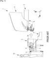
- FIG. 1 is a schematic side view of a bumper structure of a motor vehicle 1 of the prior art, during a first step of attaching a bumper face 2 to a bumper beam 3.
- the bumper structure extends generally in a longitudinal direction X corresponding to the longitudinal axis of the vehicle.
- the spatial representation of the bumper structure is supplemented by a transverse direction Y and a vertical direction Z.
- FIG. 1 shows the front part of a vehicle 1, typically a truck, and illustrates one example of a conventional device for attaching a bumper face 2 made typically of resin to a bumper beam 3 connected to a vehicle body 3.
- the bumper beam 3 is horizontally mounted and can include left-hand and right-hand side members 9 that are connected on the rear side to a vehicle body of the motor vehicle 1 and on the front side to a horizontal transverse front member of the bumper beam 3.
- the side members 9 may each comprise an upper part which is connected to the vehicle body and a lower part which is connected to the front member of the bumper beam 3.
- the bumper face 2 is fixedly mounted to the bumper beam 3 such that the bumper face 2 covers a front face of this bumper beam 3.
- a hood 4 covers the bumper assembly.
- the bumper face 2 has left-hand and right-hand bumper face side parts 2a.
- the bumper face 2 has a side opening 5 on each side part 2a.
- Each opening 5 provides access to side bolts to secure the bumper face 2 laterally to the bumper beam 3 via mounting holes 6 of the bumper face 2 and corresponding mounting holes 7 of the bumper beam 3, typically mounting holes 7 of left-hand and right-hand side members 9.
- Each opening side 5 is covered by a side cover 8.
- the cover 8 is, for example, a fog lamp cover.
- the bumper face 2 in placed on a docking device 11 mounted on wheels.
- a first operator 10 removes each cover 8 so as to leave the openings 5 visible and moves the bumper face 2 longitudinally towards the bumper beam 3 in order to align the mounting holes 6 of the bumper face 2 with the corresponding mounting holes 7 of the bumper beam 3.
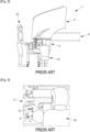
- FIG. 2 is a schematic side view of the bumper structure of the prior art, during a second step of attaching the bumper face 2 to the bumper beam 3.
- a second operator 10 manually installs bolts 12 for attaching the bumper face 2 to the side members 9 of the bumper beam 3.
- FIG. 3 is a detail view of FIG. 2 and shows how the bumper face 2 is attached to the bumper beam 3 by the second operator 10 using the bolts 12.
- FIG. 4 is a schematic side view of the bumper structure of the prior art, during a third step of attaching the bumper face 2 to the bumper beam 3.
- the second operator 10 puts the side covers 8 back in place and the first operator 10 removes the docking device 11.
- the remaining bolts are then installed by opening the hood 4.
- the remaining bolts are used to fix a front upper flange of the bumper face 2 to a face of the bumper beam 3.
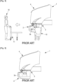
- FIG. 5 is a schematic side view of the bumper assembly structure of the prior art, once the bumper face 2 has been attached to the bumper beam 3.
- This attaching device requires the presence of side covers on the bumper face and that a lot of time is needed to align the bumper face with the bumper beam and to lock the bumper face on the bumper beam. Additionally, two operators are needed.
- FIG. 6 is a schematic side view of a bumper structure of the invention, during a first step of attaching the bumper face 2 to the bumper beam 3.
- the bumper face 2 is placed on a docking device 11 mounted on wheels.
- the bumper face 2 includes on each side part 2a a retractable positioning projection 13.
- a first operator 10 moves the bumper face 2 longitudinally towards the bumper beam 3 in order to align the retractable positioning projections 13 of the bumper face 2 with corresponding mounting holes 14 of the bumper beam 3.
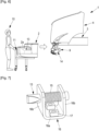
- FIG. 7 is a first detail view of FIG. 6 showing the retractable positioning projection 13.
- the retractable positioning projection 13 is typically a positioning pin 13 associated with a spring 15 and configured to retract during contact of the bumper face 2 with the bumper beam 3 and to come out by spring force when the positioning pin 13 is aligned with a positioning hole 14 of the bumper beam 3.
- the pin 13 is advantageously a beveled pin 13 or a tapered pin 13.
- a bracket 16 including two holes for the passage of the pin 14 is mounted on the bumper face 2.
- the bracket is a U-shaped bracket 16 including a bottom face 16a that is mounted on the bumper face 2 with for instance two flanged screws 17 and two faces 16b orthogonal to the bottom face 16a, each face 16b including a hole receiving the pin 13.
- An abutment 13a of the pin 13 makes it possible to limit the movement of the pin 13 in the direction of the axis passing through the two holes.
- the positioning pin 13 may be circular or square in cross-section.
- the figures illustrate the use of one pin 13 on each side member 9 with one corresponding positioning hole 14. However, a different number of pins 13 could be used, for example two pins on each side member 9 associated each with one positioning hole.
- the spring 15 is optional and could be replaced by manual action.
- FIG. 8 is a second detail view of FIG. 6 showing the positioning hole 14 of each side member 9 of the bumper beam 3.
- Each positioning hole 14 is intended to receive one positioning pin 13.
- the projection 13 can be in contact with the side member 9 along a guiding zone 18 of the side member 9 located at the front of the orifice 14.
- FIG. 9 is a schematic side view of the bumper structure of the invention, during a second step of attaching the bumper face 2 to the bumper beam 3, whereas FIG. 10 is a cross-sectional view taken along an arrow line A-A of FIG. 9 .
- the pin 13 is in its initial position, in which the pin 13 is uncompressed. Indeed, the spring 15 exerts pressure on the abutment 13a which is thus brought into contact with the face 16b located on the side of the bumper beam 3.
- the pin 13 is oriented transversely. In the initial position, the pin 13 is at the beginning of the guide zone 18 that advantageously includes a longitudinal stop 18a on which the non-retracted pin 13 rests.
- FIG. 11 is a schematic side view of the bumper structure of the invention, during a third step of attaching the bumper face 2 to the bumper beam 3, whereas FIG. 12 is a cross-sectional view taken along an arrow line A-A of FIG. 11 .
- the operator 10 pushes the bumper face 2 longitudinally towards the bumper beam 3.
- Each pin 13 passes the stop 18a and thus switches to a retracted configuration and comes into contact with the side member 9 of the vehicle body 3 along the guiding zone 18.
- the pin 13 is in an intermediate position, in which the pin 13 is pushed by the external surface of the side member 9 and compresses the spring 15 which keeps the pin 13 in contact with the side member 9.
- FIG. 13 is a schematic side view of the bumper structure of the invention, during a fourth step of attaching the bumper face 2 to the bumper beam 3, whereas FIG. 14 is a cross-sectional view taken along an arrow line A-A of FIG. 13 .
- Each pin 13 continues to slide against the side member 9 along the guiding zone 18 until the transverse pin axis coincides with the axis of the positioning hole 14 of the bumper beam 3.
- the spring 15 exerts pressure on the pin 13 which is pushed towards the inside of the positioning hole 14. Inserting the pin 13 inside the positioning hole 14 ensures locking of the bumper face 2 to the side member 9 of the bumper beam 3.
- FIG. 15 is a schematic side view of the bumper structure of the invention, once the bumper face 2 has been locked to the bumper beam 3. The operator 10 removes the docking device 11.
- FIG. 16 is a schematic side view of a bumper structure of the invention, during a fifth step of attaching the bumper face 2 to the bumper beam 3.
- the remaining bolts 19 are then installed by opening the hood 4.
- the remaining bolts 19 are used to fix a front upper flange of the bumper face 2 to a face of the bumper beam 3.
- Relative terms such as “below” or “above” or “upper” or “lower” or “horizontal” or “vertical” may be used herein to describe a relationship of one element to another element as illustrated in the Figures. It will be understood that these terms and those discussed above are intended to encompass different orientations of the device in addition to the orientation depicted in the Figures. It will be understood that when an element is referred to as being “connected” or “coupled” to another element, it can be directly connected or coupled to the other element, or intervening elements may be present. In contrast, when an element is referred to as being “directly connected” or “directly coupled” to another element, there are no intervening elements present.
Landscapes
- Engineering & Computer Science (AREA)
- Mechanical Engineering (AREA)
- Body Structure For Vehicles (AREA)
Abstract
- a bumper face (2) forming an outer face of a bumper and comprising two side parts (2a),
- a bumper beam (3) to which the bumper face (2) is intended to be attached, the bumper beam (3) restraining deformation of the bumper face (2) and being intended to be covered by the bumper face (2), the bumper beam (3) including two side members (9),
wherein the bumper structure comprises a locking system (13, 14) allowing the bumper face (2) to be locked to the bumper beam (3),
wherein the locking system (13, 14) includes a retractable positioning projection (13) arranged on each side part (2a) of the bumper face (2), and a positioning hole (14) arranged on each side member (9) of the bumper beam (3) and configured to receive a positioning projection (13) in a locking position of the locking system (13, 14).
Description
- The disclosure relates generally to a bumper structure for a motor vehicle and more particularly to a system for positioning a bumper face with respect to a bumper beam and for locking the bumper face to the bumper beam. The disclosure also relates to a method for locking a bumper face to a bumper beam. The disclosure can be applied in heavy-duty vehicles, such as trucks, buses, and construction equipment. Although the disclosure may be described with respect to a particular vehicle, the disclosure is not restricted to any particular vehicle.
- A bumper is mounted to both front and rear ends of a vehicle body. The bumper protects the vehicle body and functional devices such as lamp by absorbing collision energy when the vehicle collides with another vehicle or an object. Further, the bumper affects an aerodynamic performance of the vehicle and plays an important role in design parts. The bumper has a bumper assembly structure constructed by a bumper beam of the vehicle body, a mechanism for absorbing the collision energy, and a bumper face covering the bumper beam. The bumper beam can be formed from a high strength steel member in many cases to limit the increase in weight caused by the strengthened bumper. The bumper face is not arranged as a strengthening member, but is used to cover the bumper beam and make the bumper look more attractive. The bumper face is typically formed by a lightweight resin member that is easily deformed during a collision.
- On the current production lines, the bumper face is attached to the bumper beam using conventional bolts and these bolts must be accessible from outside the bumper face, as the vehicle hood is closed. To access these bolts, end covers of the bumper face usually have to be removed. The use of end covers limits the freedom of style and design of the bumper and makes the attachment of the bumper face to the bumper beam particularly complex.
- According to a first aspect of the disclosure, a bumper structure for a motor vehicle comprises:
- a bumper face forming an outer face of a bumper and comprising two side parts,
- a bumper beam to which the bumper face is intended to be attached, the bumper beam restraining deformation of the bumper face and being intended to be covered by the bumper face, the bumper beam including two side members,
- wherein the bumper structure comprises a locking system allowing the bumper face to be locked to the bumper beam,
- wherein the locking system includes a retractable positioning projection arranged on each side part of the bumper face, and a positioning hole arranged on each side member of the bumper beam and configured to receive a positioning projection in a locking position of the locking system.
- The first aspect of the disclosure may seek to use an automatic locking and unlocking system that eliminates the need for manual docking. During bumper docking, the retractable projection comes in contact with the bumper beam, causing the projection to retract. The projection comes out when the projection is aligned with the positioning hole which ensure that the bumper face locks onto the bumper beam. The bumper face is self guided in relation to the bumper beam, simply by contacting the positioning projections along the side members of the bumper beam. Moreover, since end covers are no longer necessary, different styles of bumper faces can be designed.
- In some examples, the bumper face is configured to be locked to the bumper beam by a movement of the bumper face from a position in which each positioning projection contacts in a retracted position with a side part of the bumper beam to a locking position in which each positioning projection extends in a non-retracted position at least partially inside a positioning hole.
- In some examples, the side members of the bumper beam are connected to a vehicle body.
- In some examples, each retractable positioning projection is a positioning pin associated with a spring and configured to retract during contact of the side part of the bumper face with the side member of the bumper beam and to come out by spring force when the positioning pin extends in a non-retracted position at least partially inside the positioning hole.
- In some examples, a U-shaped bracket including two holes receiving the pin is mounted on each side part of the bumper face.
- In some examples, an abutment of the pin makes it possible to limit the movement of the pin in the direction of the axis passing through the two holes.
- In some examples, the pin is a beveled or a tapered pin.
- In some examples, the bumper structure comprises bolts for attaching the bumper face to the bumper beam.
- In some examples, the bumper structure is a front bumper structure.
- In some examples, a motor vehicle comprises a bumper structure described above.
- In some examples, the motor vehicle is a truck.
- According to a second aspect of the disclosure, a method for locking a bumper face to a bumper beam of a motor vehicle implements a bumper structure described above.
- In some examples, the method comprises:
- providing the bumper face,
- providing the bumper beam,
- moving the bumper face towards the bumper beam, so that each positioning projection contacts, in a retracted position, a side part of the bumper beam, and then so that each positioning projection extends in a non-retracted position at least partially inside the positioning hole, thereby defining the locking position of the locking system.
- In some examples, the method further comprises:
- opening a hood of the motor vehicle and attaching the bumper face to the bumper beam using bolts.
- In some examples, the motor vehicle is a truck and the bumper structure is a front bumper structure.
- The above aspects, accompanying claims, and/or examples disclosed herein above and later below may be suitably combined with each other as would be apparent to anyone of ordinary skill in the art.
- Additional features and advantages are disclosed in the following description, claims, and drawings, and in part will be readily apparent therefrom to those skilled in the art or recognized by practicing the disclosure as described herein.
- With reference to the appended drawings, below follows a more detailed description of aspects of the disclosure cited as examples.
-
FIG. 1 is a schematic side view of a bumper structure of the prior art, during a first step of attaching a bumper face to a bumper beam. -
FIG. 2 is a schematic side view of a bumper structure of the prior art, during a second step of attaching the bumper face to the bumper beam. -
FIG. 3 is a detail view ofFIG. 2 . -
FIG. 4 is a schematic side view of a bumper structure of the prior art, during a third step of attaching the bumper face to the bumper beam. -
FIG. 5 is a schematic side view of a bumper structure of the prior art, once the bumper face has been attached to the bumper beam. -
FIG. 6 is a schematic side view of a bumper structure of the invention, during a first step of attaching the bumper face to the bumper beam. -
FIG. 7 is a first detail view ofFIG. 6 . -
FIG. 8 is a second detail view ofFIG. 6 . -
FIG. 9 is a schematic side view of a bumper structure of the invention, during a second step of attaching the bumper face to the bumper beam. -
FIG. 10 is a cross-sectional view taken along an arrow line A-A ofFIG. 9 . -
FIG. 11 is a schematic side view of a bumper structure of the invention, during a third step of attaching the bumper face to the bumper beam. -
FIG. 12 is a cross-sectional view taken along an arrow line A-A ofFIG. 11 . -
FIG. 13 is a schematic side view of a bumper structure of the invention, during a fourth step of attaching the bumper face to the bumper beam. -
FIG. 14 is a cross-sectional view taken along an arrow line A-A ofFIG. 13 . -
FIG. 15 is a schematic side view of a bumper structure of the invention, once the bumper face has been locked to the vehicle body. -
FIG. 16 is a schematic side view of a bumper structure of the invention, during a fifth step of attaching the bumper face to the bumper beam. - Aspects set forth below represent the necessary information to enable those skilled in the art to practice the disclosure.
-
FIG. 1 is a schematic side view of a bumper structure of amotor vehicle 1 of the prior art, during a first step of attaching abumper face 2 to abumper beam 3. The bumper structure extends generally in a longitudinal direction X corresponding to the longitudinal axis of the vehicle. The spatial representation of the bumper structure is supplemented by a transverse direction Y and a vertical direction Z. -
FIG. 1 shows the front part of avehicle 1, typically a truck, and illustrates one example of a conventional device for attaching abumper face 2 made typically of resin to abumper beam 3 connected to avehicle body 3. Thebumper beam 3 is horizontally mounted and can include left-hand and right-hand side members 9 that are connected on the rear side to a vehicle body of themotor vehicle 1 and on the front side to a horizontal transverse front member of thebumper beam 3. Theside members 9 may each comprise an upper part which is connected to the vehicle body and a lower part which is connected to the front member of thebumper beam 3. Thebumper face 2 is fixedly mounted to thebumper beam 3 such that thebumper face 2 covers a front face of thisbumper beam 3. Ahood 4 covers the bumper assembly. - The
bumper face 2 has left-hand and right-hand bumper faceside parts 2a. Thebumper face 2 has aside opening 5 on eachside part 2a. Eachopening 5 provides access to side bolts to secure thebumper face 2 laterally to thebumper beam 3 via mountingholes 6 of thebumper face 2 and corresponding mounting holes 7 of thebumper beam 3, typically mounting holes 7 of left-hand and right-hand side members 9. - Each
opening side 5 is covered by a side cover 8. The cover 8 is, for example, a fog lamp cover. - The
bumper face 2 in placed on adocking device 11 mounted on wheels. In this first step, afirst operator 10 removes each cover 8 so as to leave theopenings 5 visible and moves thebumper face 2 longitudinally towards thebumper beam 3 in order to align the mountingholes 6 of thebumper face 2 with the corresponding mounting holes 7 of thebumper beam 3. -
FIG. 2 is a schematic side view of the bumper structure of the prior art, during a second step of attaching thebumper face 2 to thebumper beam 3. Once the mountingholes 6 of thebumper face 2 have been aligned with the corresponding mounting holes 7 of thevehicle body 3, asecond operator 10 manually installsbolts 12 for attaching thebumper face 2 to theside members 9 of thebumper beam 3. -
FIG. 3 is a detail view ofFIG. 2 and shows how thebumper face 2 is attached to thebumper beam 3 by thesecond operator 10 using thebolts 12. -
FIG. 4 is a schematic side view of the bumper structure of the prior art, during a third step of attaching thebumper face 2 to thebumper beam 3. During this third step, thesecond operator 10 puts the side covers 8 back in place and thefirst operator 10 removes thedocking device 11. The remaining bolts are then installed by opening thehood 4. Typically, the remaining bolts are used to fix a front upper flange of thebumper face 2 to a face of thebumper beam 3. -
FIG. 5 is a schematic side view of the bumper assembly structure of the prior art, once thebumper face 2 has been attached to thebumper beam 3. - The disadvantage of this attaching device is that it requires the presence of side covers on the bumper face and that a lot of time is needed to align the bumper face with the bumper beam and to lock the bumper face on the bumper beam. Additionally, two operators are needed.
-
FIG. 6 is a schematic side view of a bumper structure of the invention, during a first step of attaching thebumper face 2 to thebumper beam 3. - The
bumper face 2 is placed on adocking device 11 mounted on wheels. Thebumper face 2 includes on eachside part 2a aretractable positioning projection 13. In this first step, afirst operator 10 moves thebumper face 2 longitudinally towards thebumper beam 3 in order to align theretractable positioning projections 13 of thebumper face 2 with corresponding mountingholes 14 of thebumper beam 3. -
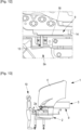
FIG. 7 is a first detail view ofFIG. 6 showing theretractable positioning projection 13. Theretractable positioning projection 13 is typically apositioning pin 13 associated with aspring 15 and configured to retract during contact of thebumper face 2 with thebumper beam 3 and to come out by spring force when thepositioning pin 13 is aligned with apositioning hole 14 of thebumper beam 3. Thepin 13 is advantageously abeveled pin 13 or a taperedpin 13. Abracket 16 including two holes for the passage of thepin 14 is mounted on thebumper face 2. The bracket is aU-shaped bracket 16 including abottom face 16a that is mounted on thebumper face 2 with for instance twoflanged screws 17 and twofaces 16b orthogonal to thebottom face 16a, eachface 16b including a hole receiving thepin 13. Anabutment 13a of thepin 13 makes it possible to limit the movement of thepin 13 in the direction of the axis passing through the two holes. - The
positioning pin 13 may be circular or square in cross-section. The figures illustrate the use of onepin 13 on eachside member 9 with one correspondingpositioning hole 14. However, a different number ofpins 13 could be used, for example two pins on eachside member 9 associated each with one positioning hole. It should be noted that thespring 15 is optional and could be replaced by manual action. -
FIG. 8 is a second detail view ofFIG. 6 showing thepositioning hole 14 of eachside member 9 of thebumper beam 3. Eachpositioning hole 14 is intended to receive onepositioning pin 13. For eachside member 9, theprojection 13 can be in contact with theside member 9 along a guidingzone 18 of theside member 9 located at the front of theorifice 14. -
FIG. 9 is a schematic side view of the bumper structure of the invention, during a second step of attaching thebumper face 2 to thebumper beam 3, whereasFIG. 10 is a cross-sectional view taken along an arrow line A-A ofFIG. 9 . Thepin 13 is in its initial position, in which thepin 13 is uncompressed. Indeed, thespring 15 exerts pressure on theabutment 13a which is thus brought into contact with theface 16b located on the side of thebumper beam 3. Thepin 13 is oriented transversely. In the initial position, thepin 13 is at the beginning of theguide zone 18 that advantageously includes alongitudinal stop 18a on which thenon-retracted pin 13 rests. -
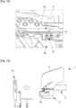
FIG. 11 is a schematic side view of the bumper structure of the invention, during a third step of attaching thebumper face 2 to thebumper beam 3, whereasFIG. 12 is a cross-sectional view taken along an arrow line A-A ofFIG. 11 . Theoperator 10 pushes thebumper face 2 longitudinally towards thebumper beam 3. Eachpin 13 passes thestop 18a and thus switches to a retracted configuration and comes into contact with theside member 9 of thevehicle body 3 along the guidingzone 18. Thepin 13 is in an intermediate position, in which thepin 13 is pushed by the external surface of theside member 9 and compresses thespring 15 which keeps thepin 13 in contact with theside member 9. -
FIG. 13 is a schematic side view of the bumper structure of the invention, during a fourth step of attaching thebumper face 2 to thebumper beam 3, whereasFIG. 14 is a cross-sectional view taken along an arrow line A-A ofFIG. 13 . Eachpin 13 continues to slide against theside member 9 along the guidingzone 18 until the transverse pin axis coincides with the axis of thepositioning hole 14 of thebumper beam 3. Thespring 15 exerts pressure on thepin 13 which is pushed towards the inside of thepositioning hole 14. Inserting thepin 13 inside thepositioning hole 14 ensures locking of thebumper face 2 to theside member 9 of thebumper beam 3. -
FIG. 15 is a schematic side view of the bumper structure of the invention, once thebumper face 2 has been locked to thebumper beam 3. Theoperator 10 removes thedocking device 11. -
FIG. 16 is a schematic side view of a bumper structure of the invention, during a fifth step of attaching thebumper face 2 to thebumper beam 3. The remainingbolts 19 are then installed by opening thehood 4. Typically, the remainingbolts 19 are used to fix a front upper flange of thebumper face 2 to a face of thebumper beam 3. - The terminology used herein is for the purpose of describing particular aspects only and is not intended to be limiting of the disclosure. As used herein, the singular forms "a," "an," and "the" are intended to include the plural forms as well, unless the context clearly indicates otherwise. As used herein, the term "and/or" includes any and all combinations of one or more of the associated listed items. It will be further understood that the terms "comprises," "comprising," "includes," and/or "including" when used herein specify the presence of stated features, integers, steps, operations, elements, and/or components, but do not preclude the presence or addition of one or more other features, integers, steps, operations, elements, components, and/or groups thereof.
- It will be understood that, although the terms first, second, etc., may be used herein to describe various elements, these elements should not be limited by these terms. These terms are only used to distinguish one element from another. For example, a first element could be termed a second element, and, similarly, a second element could be termed a first element without departing from the scope of the present disclosure.
- Relative terms such as "below" or "above" or "upper" or "lower" or "horizontal" or "vertical" may be used herein to describe a relationship of one element to another element as illustrated in the Figures. It will be understood that these terms and those discussed above are intended to encompass different orientations of the device in addition to the orientation depicted in the Figures. It will be understood that when an element is referred to as being "connected" or "coupled" to another element, it can be directly connected or coupled to the other element, or intervening elements may be present. In contrast, when an element is referred to as being "directly connected" or "directly coupled" to another element, there are no intervening elements present.
- Unless otherwise defined, all terms (including technical and scientific terms) used herein have the same meaning as commonly understood by one of ordinary skill in the art to which this disclosure belongs. It will be further understood that terms used herein should be interpreted as having a meaning consistent with their meaning in the context of this specification and the relevant art and will not be interpreted in an idealized or overly formal sense unless expressly so defined herein.
- It is to be understood that the present disclosure is not limited to the aspects described above and illustrated in the drawings; rather, the skilled person will recognize that many changes and modifications may be made within the scope of the present disclosure and appended claims. In the drawings and specification, there have been disclosed aspects for purposes of illustration only and not for purposes of limitation, the scope of the inventive concepts being set forth in the following claims.
Claims (15)
- A bumper structure for a motor vehicle (1), the bumper structure comprising:- a bumper face (2) forming an outer face of a bumper and comprising two side parts (2a),- a bumper beam (3) to which the bumper face (2) is intended to be attached, the bumper beam (3) restraining deformation of the bumper face (2) and being intended to be covered by the bumper face (2), the bumper beam (3) including two side members (9),wherein the bumper structure comprises a locking system (13, 14) allowing the bumper face (2) to be locked to the bumper beam (3),wherein the locking system (13, 14) includes a retractable positioning projection (13) arranged on each side part (2a) of the bumper face (2), and a positioning hole (14) arranged on each side member (9) of the bumper beam (3) and configured to receive a positioning projection (13) in a locking position of the locking system (13, 14).
- The bumper structure of claim 1, wherein the bumper face (2) is configured to be locked to the bumper beam (3) by a movement of the bumper face (2) from a position in which each positioning projection (13) contacts in a retracted position with a side member (9) of the bumper beam (3) to a locking position in which each positioning projection (13) extends in a non-retracted position at least partially inside a positioning hole (14).
- The bumper structure of claim 1 or 2, wherein the side members (9) of the bumper beam (3) are connected to a vehicle body.
- The bumper structure of any of claims 1-3, wherein each retractable positioning projection (13) is a positioning pin associated with a spring (15) and configured to retract during contact of the side part (2a) of the bumper face (2) with the side member (9) of the bumper beam (3) and to come out by spring force when the positioning pin (13) extends in a non-retracted position at least partially inside the positioning hole (14).
- The bumper structure of claim 4, wherein a U-shaped bracket including two holes receiving the pin (13) is mounted on each side part (2a) of the bumper face (2).
- The bumper structure of claim 4 or 5, wherein an abutment (13a) of the pin (13) makes it possible to limit the movement of the pin (13) in the direction of the axis passing through the two holes.
- The bumper structure of any of claims 4-6, wherein the pin (13) is a beveled or a tapered pin.
- The bumper structure of any of claims 1-7, wherein the bumper structure comprises bolts (19) for attaching the bumper face (2) to the bumper beam (3).
- The bumper structure of any of claims 1-8, wherein the bumper structure is a front bumper structure.
- A motor vehicle (1) comprising a bumper structure according to any of claims 1-9.
- A motor vehicle (1) of claim 10, wherein the motor vehicle (1) is a truck.
- A method for locking a bumper face (2) to a bumper beam (3) of motor vehicle (1), the method implementing a bumper structure according to claim 1.
- The method of claim 12, the method comprising:- providing the bumper face (2),- providing the bumper beam (3),- moving the bumper face (3) towards the bumper beam (3), so that each positioning projection (13) contacts, in a retracted position, a side member (9) of the bumper beam (3), and then so that each positioning projection (13) extends in a non-retracted position at least partially inside the positioning hole (13), thereby defining the locking position of the locking system (13, 14).
- The method of claim 12, wherein the method further comprises:- opening a hood (4) of the motor vehicle (1) and attaching the bumper face (2) to the bumper beam (3) using bolts (19).
- The method of any of claims 12-14, wherein the motor vehicle (1) is a truck and wherein the bumper structure is a front bumper structure.
Priority Applications (1)
| Application Number | Priority Date | Filing Date | Title |
|---|---|---|---|
| EP23217255.1A EP4570599B1 (en) | 2023-12-15 | 2023-12-15 | BUMPER STRUCTURE FOR A MOTOR VEHICLE |
Applications Claiming Priority (1)
| Application Number | Priority Date | Filing Date | Title |
|---|---|---|---|
| EP23217255.1A EP4570599B1 (en) | 2023-12-15 | 2023-12-15 | BUMPER STRUCTURE FOR A MOTOR VEHICLE |
Publications (2)
| Publication Number | Publication Date |
|---|---|
| EP4570599A1 true EP4570599A1 (en) | 2025-06-18 |
| EP4570599B1 EP4570599B1 (en) | 2026-05-20 |
Family
ID=89223477
Family Applications (1)
| Application Number | Title | Priority Date | Filing Date |
|---|---|---|---|
| EP23217255.1A Active EP4570599B1 (en) | 2023-12-15 | 2023-12-15 | BUMPER STRUCTURE FOR A MOTOR VEHICLE |
Country Status (1)
| Country | Link |
|---|---|
| EP (1) | EP4570599B1 (en) |
Citations (4)
| Publication number | Priority date | Publication date | Assignee | Title |
|---|---|---|---|---|
| JPS5784152U (en) * | 1980-11-14 | 1982-05-24 | ||
| FR2744966A1 (en) * | 1996-02-16 | 1997-08-22 | Renault | DEVICE FOR IMMOBILIZING A BUMPER ELEMENT ON A MOTOR VEHICLE BODY STRUCTURE |
| EP0720935B1 (en) * | 1995-01-03 | 1999-09-29 | Compagnie Plastic Omnium | Device for precise positioning of a bumper to a vehicle fender portion |
| CN213442430U (en) * | 2020-09-27 | 2021-06-15 | 广西玉柴新能源汽车有限公司 | Support structure of front bumper |
-
2023
- 2023-12-15 EP EP23217255.1A patent/EP4570599B1/en active Active
Patent Citations (4)
| Publication number | Priority date | Publication date | Assignee | Title |
|---|---|---|---|---|
| JPS5784152U (en) * | 1980-11-14 | 1982-05-24 | ||
| EP0720935B1 (en) * | 1995-01-03 | 1999-09-29 | Compagnie Plastic Omnium | Device for precise positioning of a bumper to a vehicle fender portion |
| FR2744966A1 (en) * | 1996-02-16 | 1997-08-22 | Renault | DEVICE FOR IMMOBILIZING A BUMPER ELEMENT ON A MOTOR VEHICLE BODY STRUCTURE |
| CN213442430U (en) * | 2020-09-27 | 2021-06-15 | 广西玉柴新能源汽车有限公司 | Support structure of front bumper |
Also Published As
| Publication number | Publication date |
|---|---|
| EP4570599B1 (en) | 2026-05-20 |
Similar Documents
| Publication | Publication Date | Title |
|---|---|---|
| US6808225B2 (en) | Double door construction for vehicle | |
| DE102012105268B4 (en) | Active hood device for a vehicle | |
| US4580823A (en) | Lock arrangement for a vehicle sliding door | |
| US20130134690A1 (en) | Hitch receiver apparatus for vehicle | |
| EP2024201A1 (en) | Bumper beam | |
| JP6177772B2 (en) | Side protection device for automobile and related automobile | |
| CN103781646A (en) | Vehicle with sliding door system | |
| US6868930B2 (en) | Automobile vehicle including associated body parts with reduced clearance | |
| CN214396658U (en) | Active anti-collision beam, anti-collision system and automobile | |
| CN213973902U (en) | Vehicle rail guard assembly and vehicle | |
| US10894565B2 (en) | Vehicle front structure having hood lock cable routing structure | |
| US12330484B2 (en) | Vehicle door system and a method for improving durability of a door system | |
| JP3215928B2 (en) | Car door | |
| KR101316110B1 (en) | Glove box coupled cowl cross member for vehicle | |
| CN214740624U (en) | Latch assemblies and vehicles | |
| US10488301B2 (en) | Jig for strength test of side door of motor vehicle | |
| CN212990481U (en) | Heavy module installation component | |
| CN115792959B (en) | A laser radar collision protection device and a car | |
| CN113994060A (en) | Vehicle door comprising a device for preventing the opening of the door in the event of a crash | |
| KR101076614B1 (en) | Carrier | |
| KR100704592B1 (en) | Door module | |
| CN214325049U (en) | Safety belt lock catch | |
| US20250162388A1 (en) | Door module of a vehicle door and vehicle door having the door module | |
| JP4941195B2 (en) | Seat belt device mounting structure | |
| EP3932709A1 (en) | A vehicle door system and a method for improving durability of a door system |
Legal Events
| Date | Code | Title | Description |
|---|---|---|---|
| PUAI | Public reference made under article 153(3) epc to a published international application that has entered the european phase |
Free format text: ORIGINAL CODE: 0009012 |
|
| STAA | Information on the status of an ep patent application or granted ep patent |
Free format text: STATUS: THE APPLICATION HAS BEEN PUBLISHED |
|
| AK | Designated contracting states |
Kind code of ref document: A1 Designated state(s): AL AT BE BG CH CY CZ DE DK EE ES FI FR GB GR HR HU IE IS IT LI LT LU LV MC ME MK MT NL NO PL PT RO RS SE SI SK SM TR |
|
| STAA | Information on the status of an ep patent application or granted ep patent |
Free format text: STATUS: REQUEST FOR EXAMINATION WAS MADE |
|
| 17P | Request for examination filed |
Effective date: 20251218 |
|
| GRAP | Despatch of communication of intention to grant a patent |
Free format text: ORIGINAL CODE: EPIDOSNIGR1 |
|
| STAA | Information on the status of an ep patent application or granted ep patent |
Free format text: STATUS: GRANT OF PATENT IS INTENDED |
|
| INTG | Intention to grant announced |
Effective date: 20260129 |
|
| GRAS | Grant fee paid |
Free format text: ORIGINAL CODE: EPIDOSNIGR3 |
|
| GRAA | (expected) grant |
Free format text: ORIGINAL CODE: 0009210 |
|
| STAA | Information on the status of an ep patent application or granted ep patent |
Free format text: STATUS: THE PATENT HAS BEEN GRANTED |