EP4570596A1 - Cable retraction device - Google Patents
Cable retraction device Download PDFInfo
- Publication number
- EP4570596A1 EP4570596A1 EP23217297.3A EP23217297A EP4570596A1 EP 4570596 A1 EP4570596 A1 EP 4570596A1 EP 23217297 A EP23217297 A EP 23217297A EP 4570596 A1 EP4570596 A1 EP 4570596A1
- Authority
- EP
- European Patent Office
- Prior art keywords
- cable
- retraction device
- subsystem
- drag structure
- retractable
- Prior art date
- Legal status (The legal status is an assumption and is not a legal conclusion. Google has not performed a legal analysis and makes no representation as to the accuracy of the status listed.)
- Pending
Links
Images


Classifications
-
- B—PERFORMING OPERATIONS; TRANSPORTING
- B60—VEHICLES IN GENERAL
- B60R—VEHICLES, VEHICLE FITTINGS, OR VEHICLE PARTS, NOT OTHERWISE PROVIDED FOR
- B60R16/00—Electric or fluid circuits specially adapted for vehicles and not otherwise provided for; Arrangement of elements of electric or fluid circuits specially adapted for vehicles and not otherwise provided for
- B60R16/02—Electric or fluid circuits specially adapted for vehicles and not otherwise provided for; Arrangement of elements of electric or fluid circuits specially adapted for vehicles and not otherwise provided for electric constitutive elements
- B60R16/023—Electric or fluid circuits specially adapted for vehicles and not otherwise provided for; Arrangement of elements of electric or fluid circuits specially adapted for vehicles and not otherwise provided for electric constitutive elements for transmission of signals between vehicle parts or subsystems
- B60R16/027—Electric or fluid circuits specially adapted for vehicles and not otherwise provided for; Arrangement of elements of electric or fluid circuits specially adapted for vehicles and not otherwise provided for electric constitutive elements for transmission of signals between vehicle parts or subsystems between relatively movable parts of the vehicle, e.g. between steering wheel and column
-
- B—PERFORMING OPERATIONS; TRANSPORTING
- B60—VEHICLES IN GENERAL
- B60R—VEHICLES, VEHICLE FITTINGS, OR VEHICLE PARTS, NOT OTHERWISE PROVIDED FOR
- B60R16/00—Electric or fluid circuits specially adapted for vehicles and not otherwise provided for; Arrangement of elements of electric or fluid circuits specially adapted for vehicles and not otherwise provided for
- B60R16/02—Electric or fluid circuits specially adapted for vehicles and not otherwise provided for; Arrangement of elements of electric or fluid circuits specially adapted for vehicles and not otherwise provided for electric constitutive elements
- B60R16/0207—Wire harnesses
- B60R16/0215—Protecting, fastening and routing means therefor
-
- H—ELECTRICITY
- H02—GENERATION; CONVERSION OR DISTRIBUTION OF ELECTRIC POWER
- H02G—INSTALLATION OF ELECTRIC CABLES OR LINES, OR OF COMBINED OPTICAL AND ELECTRIC CABLES OR LINES
- H02G11/00—Arrangements of electric cables or lines between relatively-movable parts
- H02G11/006—Arrangements of electric cables or lines between relatively-movable parts using extensible carrier for the cable, e.g. self-coiling spring
-
- H—ELECTRICITY
- H02—GENERATION; CONVERSION OR DISTRIBUTION OF ELECTRIC POWER
- H02G—INSTALLATION OF ELECTRIC CABLES OR LINES, OR OF COMBINED OPTICAL AND ELECTRIC CABLES OR LINES
- H02G3/00—Installations of electric cables or lines or protective tubing therefor in or on buildings, equivalent structures or vehicles
- H02G3/02—Details
- H02G3/04—Protective tubing or conduits, e.g. cable ladders or cable troughs
- H02G3/0406—Details thereof
-
- H—ELECTRICITY
- H02—GENERATION; CONVERSION OR DISTRIBUTION OF ELECTRIC POWER
- H02G—INSTALLATION OF ELECTRIC CABLES OR LINES, OR OF COMBINED OPTICAL AND ELECTRIC CABLES OR LINES
- H02G3/00—Installations of electric cables or lines or protective tubing therefor in or on buildings, equivalent structures or vehicles
- H02G3/02—Details
- H02G3/04—Protective tubing or conduits, e.g. cable ladders or cable troughs
- H02G3/0437—Channels
- H02G3/045—Channels provided with perforations or slots permitting introduction or exit of wires
Definitions
- the invention relates to a cable retraction device for a retractable or movable subsystem of a vehicle system, in particular a steering subsystem, and to a vehicle comprising such cable retraction device.
- retractable or movable subsystems are suited for increasing a driver's comfort, for example, in the form of adjustable sub-structures, such as adjustable passenger seats, a retractable steering column, adjustable control elements of the vehicle system, and the like.
- Retractable or movable subsystems are also suited for expanding a functionality of the vehicle system, for example, in the form of convertible subsystems, such as modifiable vehicle compartments, a convertible vehicle roof, retractable trailer hitch arrangements, and the like.
- a retractable or movable subsystem includes, or bears, one or more functionalities of the vehicle system which are operatively connected with other components of the vehicle system
- a movability of the subsystem needs to comply with the requirement of safeguarding an operative connection between such functionalities and other components of the vehicle system. This applies, especially, where such functionalities are safety-relevant and/or where legal constraints pose an increased demand on safeguarding an operative connection across movable portions of a vehicle.
- a cable retraction device for a retractable or movable subsystem of a vehicle system, preferably a steering subsystem.
- the cable retraction device comprises a bendable drag structure configured to support a cable harness of the subsystem.
- the bendable drag structure defines a bendable supporting surface for the cable harness.
- the supporting surface comprises at least two sections which extend parallel to each other in a length direction of the bendable drag structure and which at a given bending of the drag structure have different radii of curvature.
- the cable retraction device facilitates accommodating in the cable retraction device a cable harness which comprises a plurality of cables, such as optical and/or electric cables, in particular, for complex and/or security-relevant functionalities of the vehicle system.
- a cable harness which comprises a plurality of cables, such as optical and/or electric cables, in particular, for complex and/or security-relevant functionalities of the vehicle system.
- This is achieved by enabling that different cables of the cable harness which have different thicknesses be supported, adjacent each other, by different ones of the at least two sections.
- different ones of the at least two sections can be configured to support one or more different cables of the cable harness which have different thicknesses, respectively.
- any of the above effects is advantageous, in particular, in connection with complex and/or safety-relevant functionalities of the vehicle system which are included in, or borne by, the retractable or movable subsystem.
- This is, because such functionalities typically demand a high level of reliability and/or durability, over large temperature ranges, and they typically involve operative connections by cables having different thicknesses.
- the at least two sections of the supporting surface may be provided for supporting different ones of at least two cables having different diameters among a plurality of cables of the cable harness.
- a difference between the radii of curvature of at least two sections of the supporting surface may correspond to a difference between the radii of at least two cables associated with the respective sections of the supporting surface and having different diameters among the plurality of cables of the cable harness.
- a difference between the radii of curvature of at least two sections of the supporting surface may correspond to a difference between the diameters of at least two cables associated with the respective sections of the supporting surface and having different diameters among the plurality of cables of the cable harness. In this way, a fixation of the cables relative to the length direction on the bendable drag structure by means of confining elements, in particular by means of holding pins, is facilitated.
- a difference between the radii of curvature of at least two sections of the supporting surface may correspond to an intermediate value which lies between a difference between the radii and a difference between the diameters of at least two cables associated with the respective sections of the supporting surface and having different diameters among the plurality of cables of the cable harness.
- the radius and/or the diameter of any of the at least two cables may correspond to an effective radius and/or an effective diameter of the respective cable in a region of the given bending of the drag structure, wherein the effective radius and/or the effective diameter are measured in a radial direction with respect to a center of the bending.
- the respective cable comprises elastic material, such as an elastic insulation, and when a tensile and/or a compressive force acting on at least a portion of the cable at the given bending causes elastic deformation of a cross-section of the cable at the bending.
- the radius of the cable may be defined as one-half of a height of the cross-section of the cable at the bending and/or the radius may be measured with respect to a height position within the cross-section of the cable which provides that a largest one of both a compressive force acting at an inward portion of the cable facing towards the center of the bending and a tensile force acting at an outward portion of the cable facing away from the center of the bending is minimized.
- the radius and/or the diameter of any of the at least two cables may be further defined with respect to a prevailing, a mean and/or an extreme temperature within a temperature range for which the cable retraction device is configured.
- the temperature range may be from -45°C to +95°C.
- the difference between the radii of curvature of the at least two sections of the supporting surface may correspond to a difference between a height of each of the at least two sections with respect to a profile of the bendable supporting surface.
- the drag structure may further comprise at least one separator contour configured to separate adjacent ones of the at least two sections of the supporting surface in a width direction of the drag structure.
- the drag structure may further comprise at least one bending limitation contour adapted to limit a bending of the drag structure. In this way, a risk of breakage of an operational connection provided through the cable harness, in consequence of excessive bending of the cable harness, is further reduceable.
- the drag structure may further comprise at least one confining element configured to hold one or more cables of the cable harness in a proximity to the supporting surface.
- the at least one confining element may comprise at least one holding pin which is attachable to at least one pin connecting contour of the bendable drag structure. In this way, a risk of accidental misarrangement of one or more cables with respect to the supporting surface and/or its corresponding sections, in particular, by vibration or by any other movement of the subsystem, is further reduceable.
- the at least one confining element may further provide a fixation of one or more cables of the cable harness relative to the length direction of the bendable drag structure.
- the bendable drag structure may comprise a drag chain having a plurality of drag chain links which are movably connected to each other, the plurality of drag chain links defining the supporting surface.
- the supporting surface can be at least partially defined as a geometric envelope of at least a portion of the plurality of drag chain links.
- any of the at least one separator contour, the at least one bending limitation contour, and/or the at least one confining element may be formed on one or more of the drag chain links.
- at least one separator contour, at least one bending limitation contour, and/or at least one confining element may be formed on each one of the plurality of drag chain links.
- the cable retraction device may further comprise a plurality of drag structure mounts adapted to connect a stationary end of the drag structure to a stationary portion of the subsystem and to connect a retractable end of the drag structure to a retractable or movable portion of the subsystem.
- the cable retraction device may further comprise at least one electric connector arranged at any of the drag structure mounts and configured to facilitate an electric connection between one or more cables of the cable harness and one or more external devices external to the cable retraction device.
- the subsystem may be a steering subsystem.
- the bendable drag structure may be adapted to be arranged at least partially in a retractable steering column of the steering subsystem when a cable harness of the steering subsystem is supported by means of the drag structure.
- the cable retraction device may further comprise a cable harness for the retractable or movable subsystem, wherein the cable harness is supported by means of the drag structure.
- a steering subsystem for a vehicle system comprises a cable retraction device as provided herein, at least one stationary portion, a retractable steering column having at least one retractable portion, and a steering wheel arrangement attached to the at least one retractable portion of the steering column and comprising at least one operable steering wheel functionality.
- the cable harness is connected to the at least one operable steering wheel functionality for operatively connecting the at least one operable steering wheel functionality to a control unit of the vehicle.
- the at least one operable steering wheel functionality may comprise a steering input detection functionality configured to detect a steering input provided by a user of the vehicle via the steering wheel arrangement.
- the supply unit may comprise a control unit configured to process a steering input signal received from the steering input detection functionality via the cable harness.
- the at least one stationary portion of the steering system may comprise a stationary portion of the retractable steering column.
- the control unit of the vehicle may comprise a control unit of the steering system, which is arrangeable on the stationary portion, in particular in the stationary portion, of the retractable steering column.
- a vehicle comprises a cable retraction device as provided herein and/or a steering system as provided herein.
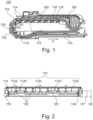
- Fig. 1 shows a longitudinal cross-section of a cable retraction device 100, for example, for a retractable or movable subsystem of a vehicle system.
- the cable retraction device 100 comprises a stationary drag structure mount 160 and a retractable drag structure mount 170, which are movable relative to each other. As indicated by the arrow, the retractable drag structure mount 170 is movable parallel to an extraction direction E of the cable retraction device 100.
- Fig. 1 shows the cable retraction device 100 in a retracted position of the retractable drag structure mount 170. Between the stationary drag structure mount 160 and the retractable drag structure mount 170, a bendable drag structure 110 of the cable retraction device 100 extends.
- the bendable drag structure 110 defines a bendable supporting surface 112 on which a bendable cable harness 180 is arranged.
- the cable retraction device 100 is adapted to provide a flexible support for the cable harness 180 between a stationary portion of a retractable or movable subsystem of the vehicle system, to which the stationary drag structure mount 160 is mountable, and a retractable or movable portion of the subsystem, to which the retractable drag structure mount 170 is mountable.
- the bendable drag structure 110 comprises a drag chain having a plurality of drag chain links 114.
- the drag chain links 114 are movably connected to each other and define the supporting surface 112.
- the bendable drag structure 110 comprises a different type of a bendable structure, for example, a belt.
- the bendable drag structure 110 is formed to define multiple sections 112a - 112e of the supporting surface 112.
- the sections 112a - 112e are arranged alongside each other in a width direction of the bendable drag structure 110 and extend, essentially parallel to each other, in a length direction of the bendable drag structure 110.
- the multiple sections 112a - 112e of the supporting surface 112 are configured to exhibit different radii of curvature R1, R2 when the bendable drag structure 110 is bent at any given length.
- the multiple sections 112a - 112e of the supporting surface 112 are provided for supporting different ones among a plurality of cables contained in the cable harness 180. Sections of the supporting surface 112 which have different radii of curvature R1, R2 are provided for supporting cables of different thickness, or diameter, among the plurality of cables in the cable harness 180.
- a difference between the radii of curvature R1, R2 of the multiple sections of the supporting surface 120 corresponds in some examples to a difference between the radii of the cables among the plurality of cables in the cable harness 180 which are arranged on the respective sections of the supporting surface 120. Furthermore, in some examples, the cables in the cable harness 180 are arranged adjacent each other on the supporting surface 120, i.e., with no cables incidentally crossing or overlaying each other.
- the bendable drag structure 110 comprises bending limitation contours 116, 118, which are arranged pairwise on each of the drag chain links 114.
- the bending limitation contours 116, 118 of neighboring drag chain links 114 are configured to engage, when a predefined degree of bending of the bendable drag structure 110 is reached. In this situation, the bending limitation contours 116, 118 block the bendable drag structure 110 from bending further. In this way, a maximal bending stress, as well as a corresponding maximal tensile and/or compressive stress, which is exerted on the cable harness 180 when the bendable drag structure 110 is bent, can be limited. In addition, in this way, a trajectory of the bendable drag structure 110 when the retractable drag structure mount 170 is moved parallel to the extraction direction E is essentially controllable.
- the bendable drag structure 110 further includes confining elements in the form of holding pins 122, which are attached to any of the drag chain links 114 by means of pin connecting contours 124 formed on each of the drag chain links 114.
- the holding pins 122 are provided to retain the cables of the cable harness 180 in a proximity to the supporting surface 112. This applies, especially, in a region where the bendable drag structure 110 is bent, since an intrinsic stiffness or elasticity of the cables may push some, or all, of the cables away from the supporting surface 112.
- bending limitation contours 116, 118 and confining elements 122, 124 are provided on each of the drag chain links 114.
- a bending limitation contour and/or a confining element is formed only on some of the drag chain links 114 or only at one or more selected positions over a length of the bendable drag structure 110.
- Fig. 2 shows a cross-section of a drag chain link 114 of the bendable drag structure 110.
- the supporting surface 112 includes multiple sections 112a - 112e which are arranged adjacent each other in a width direction of the drag chain link 114. Different ones of the sections 112a - 112e have different heights H1, H2 with respect to the profile of the drag chain link 114. In the example, the sections 112a, 112c and 112e have a first height H1, and the sections 112b and 112d have a second height H2.
- the supporting surface 112 When the bendable drag structure 110 is bent about a center of curvature which lies beneath the drag chain link 114, the supporting surface 112 will have a larger radius of curvature in the sections 112b and 112d, whereas the supporting surface 112 will have a smaller radius of curvature in the sections 112a, 112c and 112e.
- the difference between the radii of curvature is in accordance with the difference between the heights H 1, H2.
- sections 112a, 112c and 112e are accordingly provided for supporting cables having a relatively larger thickness, or a larger diameter, among the cables in the cable harness 180.
- sections 112 B and 112 D are provided for supporting cables having a relatively smaller thickness, or a smaller diameter.
- separator contours 120 are arranged.
- the separator contours 120 serve for confining a lateral movement of any cables which are arranged on the supporting surface 112.
- the separator contours 120 serve for confining any incidental movement of a cable, for example, due to vibration or movement of the cable retraction device 100, within the respective section 112a - 112e of the supporting surface 112, to maintain the aforesaid functionality of the sections 112a - 112e for each cable.
- the holding pins 122 extend over a full width of the supporting surface 112. In this way, cables arranged in any of the sections 112a - 112e are securely confined in their vertical motion to a proximity of the supporting surface 112. In some examples, at least some of the holding pins 122 additionally provide a fixation of at least some of the cables relative to a length direction of the bendable drag structure 110. In this way, the transmission of tensile and/or compressive stress over longer portions of the cable harness 180 is avoided.
- bending limitation contours 118 are arranged at both lateral extremities of the drag chain link 114.
- Fig. 3 shows a cutaway view of a retractable subsystem 300 for a vehicle system.
- the retractable subsystem 300 is a steering subsystem which includes a retractable steering column.
- the retractable steering column comprises a stationary portion 310 in which a retractable portion 320 of the steering column is slidably arranged.
- Fig. 3 shows the retractable subsystem 300 in a retracted position of the steering column.
- the retractable portion 320 can be moved to one or more extended positions of the retractable subsystem 300 by moving the retractable portion 320 relative to the stationary portion 310 parallel to the extension direction E, for example, to meet a driver's needs and/or preferences.
- parts of a steering wheel arrangement including a bearing and a mounting plate 312 for the steering wheel, are arranged.
- the retractable subsystem 300 includes a cable retraction device 100 as described in connection with Figs 1 and 2 .
- a cable retraction device 100 As described in connection with Figs 1 and 2 .
- an upper part of the stationary portion 310 which covers the cable retraction device 100 and to which the stationary drag structure mount 160 is mounted, has been cut away in Fig. 3 .
- the cable retraction device 100 is adapted to provide a flexible operative connection between one or more steering wheel functionalities and one or more devices external to the subsystem 300, for example, a control unit and/or a battery of the vehicle system, via the cable harness 180.
- a comparison with Fig. 2 shows that in the subsystem 300 cables 180a, which have a larger diameter, are arranged in sections 112a, 112c and 112e of the supporting surface 112 of the cable retraction device 100, as these sections define a smaller radius of curvature R1 of the supporting surface 112 of the bendable drag structure 110. Moreover, cables 180b, which have a smaller diameter, are arranged in sections 112b and 112d of the supporting surface 112, as these sections define a larger radius of curvature of the supporting surface 112 of the bendable drag structure 110.
- Fig. 4 shows a perspective view of the retractable subsystem 300.
- the cable retraction device 100 is arranged in the retractable steering column 310, 320.
- the cable retraction device 100 is provided with electric connectors 340, which are arranged at the stationary drag structure mount 160 and which facilitate an electric connection between the cables 180a, 180b of the cable harness 180 and an external device, such as a battery and/or a control unit of the vehicle system.
- Fig. 5 shows schematically and exemplarily a vehicle 500.
- the vehicle 500 has a vehicle system 510, which may include any functional and/or controllable elements provided in the vehicle 500.
- the vehicle system 510 includes a steering system 520.
- the steering system 520 comprises a steering gear 522 acting on any steerable wheels of the vehicle 500.
- the steering gear 522 is operated by means of an electric actuator 524 which is powered by a battery 550 of the vehicle 500 and is controlled by means of a control unit 540 of the vehicle system 510.
- the control unit 540 is adapted to receive steering input signals which are indicative of a steering input provided by a driver of the vehicle 500 via a steering wheel arrangement 538 of the steering system 520.
- a steering input is sensorily detected, and transmitted to the control unit 540, by means of a steering input detection functionality of the steering wheel arrangement 538.
- the steering system 520 includes a retractable steering subsystem 530, which has a retractable steering column, as described, for example, in connection with the retractable subsystem 300 in Figs. 3 and 4 .
- the steering subsystem 530 comprises a stationary portion 532 and a retractable portion 534. As indicated by the double arrow, the retractable portion 534 can be moved relative to the stationary portion 532 parallel to an extraction direction of the steering subsystem 530.
- the steering subsystem 530 further includes a cable retraction device 536, for example, in accordance with the cable retraction device 100 as described above in connection with Figs. 1 to 4 .
- the steering wheel arrangement 538 is attached to the retractable portion 534 and includes operable steering wheel functionalities.
- the cable retraction device 536 provides a flexible operative connection between such steering wheel functionalities and at least one of the control unit 540 and the battery 550.
- One of the steering wheel functionalities is the steering input detection functionality, which is adapted to detect a steering input provided by the driver via a steering wheel of the steering wheel arrangement 538 and to transmit a corresponding steering input signal towards the control unit 540.
- control unit 540 is arranged on the stationary portion 532, for example, inside the stationary portion 532, of the retractable steering subsystem 530.
- the cable retraction devices 100, 536 as described herein, facilitate a compact arrangement of a control unit of the vehicle 500 in a steering subsystem 530.
Landscapes
- Engineering & Computer Science (AREA)
- Mechanical Engineering (AREA)
- Architecture (AREA)
- Civil Engineering (AREA)
- Structural Engineering (AREA)
- Electric Cable Arrangement Between Relatively Moving Parts (AREA)
Abstract
Description
- The invention relates to a cable retraction device for a retractable or movable subsystem of a vehicle system, in particular a steering subsystem, and to a vehicle comprising such cable retraction device.
- In a vehicle, retractable or movable subsystems are suited for increasing a driver's comfort, for example, in the form of adjustable sub-structures, such as adjustable passenger seats, a retractable steering column, adjustable control elements of the vehicle system, and the like. Retractable or movable subsystems are also suited for expanding a functionality of the vehicle system, for example, in the form of convertible subsystems, such as modifiable vehicle compartments, a convertible vehicle roof, retractable trailer hitch arrangements, and the like.
- In cases in which a retractable or movable subsystem includes, or bears, one or more functionalities of the vehicle system which are operatively connected with other components of the vehicle system, a movability of the subsystem needs to comply with the requirement of safeguarding an operative connection between such functionalities and other components of the vehicle system. This applies, especially, where such functionalities are safety-relevant and/or where legal constraints pose an increased demand on safeguarding an operative connection across movable portions of a vehicle.
- There exists a continuous need for improved techniques in connection with retractable or movable subsystems of a vehicle system.
- The problem is solved by means of a cable retraction device according to claim 1, by means of a steering system according to claim 13, and by means of a vehicle according to claim 15.
- According to a first aspect, a cable retraction device for a retractable or movable subsystem of a vehicle system, preferably a steering subsystem, is provided. The cable retraction device comprises a bendable drag structure configured to support a cable harness of the subsystem. The bendable drag structure defines a bendable supporting surface for the cable harness. The supporting surface comprises at least two sections which extend parallel to each other in a length direction of the bendable drag structure and which at a given bending of the drag structure have different radii of curvature.
- By providing at least two sections of the supporting surface which have different radii of curvature, the cable retraction device facilitates accommodating in the cable retraction device a cable harness which comprises a plurality of cables, such as optical and/or electric cables, in particular, for complex and/or security-relevant functionalities of the vehicle system. This is achieved by enabling that different cables of the cable harness which have different thicknesses be supported, adjacent each other, by different ones of the at least two sections. In other words, different ones of the at least two sections can be configured to support one or more different cables of the cable harness which have different thicknesses, respectively.
- By supporting cables having different thicknesses by different sections of the supporting surface, a tensile and/or compressive stress, which is exerted on the cables parallel to the length direction when a bending of the drag structure is changed, can be reduced. Thus, a risk of breakage of an operative connection through the cable harness, by breakage of one or more of the cable connections, in consequence of different or excessive tensile and/or compressive stress acting on the cables, is reduced.
- Moreover, wear of the cables due to different tensile and/or compressive stress parallel to the length direction in the case of frequent changes of a bending of the bendable drag structure can be avoided or reduced. A durability and/or a reliability of the operative connection can thus be increased.
- By reducing at least one of a tensile and/or compressive stress acting on the cables in the cable harness and a difference in such stress between different cables of the cable harness, a fixation of the cable harness relative to the length direction on the bendable drag structure at one or more positions over a length of the bendable drag structure is also facilitated. In this way, an occurrence of tensile and/or compressive stress being transmitted over larger portions of the cable harness, in particular on electric connections of the cable harness, can be reduced. This applies to situations in which a bending of the bendable drag structure is changed, and/or in which tensile and/or compressive stress acts on the cable harness as a result of thermomechanical expansion and/or contraction, in particular, under varying climatic or thermal conditions of the subsystem. A reliability of operative connections provided by the cable harness can thus be improved over large temperature ranges.
- Any of the above effects is advantageous, in particular, in connection with complex and/or safety-relevant functionalities of the vehicle system which are included in, or borne by, the retractable or movable subsystem. This is, because such functionalities typically demand a high level of reliability and/or durability, over large temperature ranges, and they typically involve operative connections by cables having different thicknesses.
- The at least two sections of the supporting surface may be provided for supporting different ones of at least two cables having different diameters among a plurality of cables of the cable harness. A difference between the radii of curvature of at least two sections of the supporting surface may correspond to a difference between the radii of at least two cables associated with the respective sections of the supporting surface and having different diameters among the plurality of cables of the cable harness. In this way, a difference in tensile and/or compressive stress between the at least two cables when a bending of the bendable drag structure is changed can be minimized.
- In addition, or as an alternative, a difference between the radii of curvature of at least two sections of the supporting surface may correspond to a difference between the diameters of at least two cables associated with the respective sections of the supporting surface and having different diameters among the plurality of cables of the cable harness. In this way, a fixation of the cables relative to the length direction on the bendable drag structure by means of confining elements, in particular by means of holding pins, is facilitated.
- In addition, or as an alternative, a difference between the radii of curvature of at least two sections of the supporting surface may correspond to an intermediate value which lies between a difference between the radii and a difference between the diameters of at least two cables associated with the respective sections of the supporting surface and having different diameters among the plurality of cables of the cable harness. In this way, a compromise between a reduced difference in tensile and/or compressive stress between the at least two cables when a bending of the bendable drag structure is changed and improved fixation of the cables relative to the length direction on the bendable drag structure by means of confining elements, in particular by means of holding pins, is facilitated.
- The radius and/or the diameter of any of the at least two cables may correspond to an effective radius and/or an effective diameter of the respective cable in a region of the given bending of the drag structure, wherein the effective radius and/or the effective diameter are measured in a radial direction with respect to a center of the bending. This is advantageous, in particular, when the respective cable comprises elastic material, such as an elastic insulation, and when a tensile and/or a compressive force acting on at least a portion of the cable at the given bending causes elastic deformation of a cross-section of the cable at the bending. In this way, the aforesaid advantages regarding a reduction of tensile and/or compressive stress in the cable can be adapted to, in particular optimized for, an effective geometry of the cable at the bending. In connection with this, the radius of the cable may be defined as one-half of a height of the cross-section of the cable at the bending and/or the radius may be measured with respect to a height position within the cross-section of the cable which provides that a largest one of both a compressive force acting at an inward portion of the cable facing towards the center of the bending and a tensile force acting at an outward portion of the cable facing away from the center of the bending is minimized.
- In addition, the radius and/or the diameter of any of the at least two cables, as defined in the foregoing, may be further defined with respect to a prevailing, a mean and/or an extreme temperature within a temperature range for which the cable retraction device is configured. For a use of the cable retraction device in a vehicle, the temperature range may be from -45°C to +95°C. In this way, tensile and/or compressive stress in the cable due to possible thermomechanical expansion and/or contraction of at least portions of the cable, which may affect the cross-section of the cable at the bending, can be further compensated. Additionally, in this way, a temperature-dependency of one or more elastic characteristics of the elastic material comprised by the cable, in particular, a dependency of an elasticity of the elastic material on varying climatic or thermal conditions of the subsystem, may be accounted for.
- The difference between the radii of curvature of the at least two sections of the supporting surface may correspond to a difference between a height of each of the at least two sections with respect to a profile of the bendable supporting surface.
- The drag structure may further comprise at least one separator contour configured to separate adjacent ones of the at least two sections of the supporting surface in a width direction of the drag structure. In this way, a risk of accidental misarrangement of one or more cables with respect to their corresponding section of the supporting surface, in particular, by vibration or by any other movement of the subsystem, is reduceable.
- The drag structure may further comprise at least one bending limitation contour adapted to limit a bending of the drag structure. In this way, a risk of breakage of an operational connection provided through the cable harness, in consequence of excessive bending of the cable harness, is further reduceable.
- The drag structure may further comprise at least one confining element configured to hold one or more cables of the cable harness in a proximity to the supporting surface. The at least one confining element may comprise at least one holding pin which is attachable to at least one pin connecting contour of the bendable drag structure. In this way, a risk of accidental misarrangement of one or more cables with respect to the supporting surface and/or its corresponding sections, in particular, by vibration or by any other movement of the subsystem, is further reduceable. The at least one confining element may further provide a fixation of one or more cables of the cable harness relative to the length direction of the bendable drag structure.
- The bendable drag structure may comprise a drag chain having a plurality of drag chain links which are movably connected to each other, the plurality of drag chain links defining the supporting surface. The supporting surface can be at least partially defined as a geometric envelope of at least a portion of the plurality of drag chain links.
- Any of the at least one separator contour, the at least one bending limitation contour, and/or the at least one confining element may be formed on one or more of the drag chain links. In particular, at least one separator contour, at least one bending limitation contour, and/or at least one confining element may be formed on each one of the plurality of drag chain links.
- The cable retraction device may further comprise a plurality of drag structure mounts adapted to connect a stationary end of the drag structure to a stationary portion of the subsystem and to connect a retractable end of the drag structure to a retractable or movable portion of the subsystem.
- The cable retraction device may further comprise at least one electric connector arranged at any of the drag structure mounts and configured to facilitate an electric connection between one or more cables of the cable harness and one or more external devices external to the cable retraction device.
- The subsystem may be a steering subsystem. The bendable drag structure may be adapted to be arranged at least partially in a retractable steering column of the steering subsystem when a cable harness of the steering subsystem is supported by means of the drag structure.
- The cable retraction device may further comprise a cable harness for the retractable or movable subsystem, wherein the cable harness is supported by means of the drag structure.
- According to another aspect, a steering subsystem for a vehicle system is provided. The steering subsystem comprises a cable retraction device as provided herein, at least one stationary portion, a retractable steering column having at least one retractable portion, and a steering wheel arrangement attached to the at least one retractable portion of the steering column and comprising at least one operable steering wheel functionality. The cable harness is connected to the at least one operable steering wheel functionality for operatively connecting the at least one operable steering wheel functionality to a control unit of the vehicle.
- The at least one operable steering wheel functionality may comprise a steering input detection functionality configured to detect a steering input provided by a user of the vehicle via the steering wheel arrangement. The supply unit may comprise a control unit configured to process a steering input signal received from the steering input detection functionality via the cable harness.
- The at least one stationary portion of the steering system may comprise a stationary portion of the retractable steering column. The control unit of the vehicle may comprise a control unit of the steering system, which is arrangeable on the stationary portion, in particular in the stationary portion, of the retractable steering column.
- According to another aspect, a vehicle is provided. The vehicle comprises a cable retraction device as provided herein and/or a steering system as provided herein.
- Further details, advantages and objects of the invention become clear from the following detailed description and the drawings. There is shown in:
- Fig. 1
- a cross section of a cable retraction device according to an example;
- Fig. 2
- a cross section of a drag chain link according to an example;
- Fig. 3
- a cut-away view of a retractable or movable subsystem according to an example;
- Fig. 4
- a perspective view of the retractable or movable subsystem of
Fig. 3 , and - Fig. 5
- a vehicle according to an example.
-
Fig. 1 shows a longitudinal cross-section of acable retraction device 100, for example, for a retractable or movable subsystem of a vehicle system. Thecable retraction device 100 comprises a stationarydrag structure mount 160 and a retractabledrag structure mount 170, which are movable relative to each other. As indicated by the arrow, the retractabledrag structure mount 170 is movable parallel to an extraction direction E of thecable retraction device 100.Fig. 1 shows thecable retraction device 100 in a retracted position of the retractabledrag structure mount 170. Between the stationarydrag structure mount 160 and the retractabledrag structure mount 170, abendable drag structure 110 of thecable retraction device 100 extends. Thebendable drag structure 110 defines a bendable supportingsurface 112 on which abendable cable harness 180 is arranged. Thecable retraction device 100 is adapted to provide a flexible support for thecable harness 180 between a stationary portion of a retractable or movable subsystem of the vehicle system, to which the stationarydrag structure mount 160 is mountable, and a retractable or movable portion of the subsystem, to which the retractabledrag structure mount 170 is mountable. - In the shown example, the
bendable drag structure 110 comprises a drag chain having a plurality of drag chain links 114. Thedrag chain links 114 are movably connected to each other and define the supportingsurface 112. In other examples, thebendable drag structure 110 comprises a different type of a bendable structure, for example, a belt. - As discussed in more detail below, in connection with
Fig. 2 , thebendable drag structure 110 is formed to definemultiple sections 112a - 112e of the supportingsurface 112. Thesections 112a - 112e are arranged alongside each other in a width direction of thebendable drag structure 110 and extend, essentially parallel to each other, in a length direction of thebendable drag structure 110. Themultiple sections 112a - 112e of the supportingsurface 112 are configured to exhibit different radii of curvature R1, R2 when thebendable drag structure 110 is bent at any given length. Themultiple sections 112a - 112e of the supportingsurface 112 are provided for supporting different ones among a plurality of cables contained in thecable harness 180. Sections of the supportingsurface 112 which have different radii of curvature R1, R2 are provided for supporting cables of different thickness, or diameter, among the plurality of cables in thecable harness 180. - By arranging a cable having a larger thickness on a section of the supporting
surface 112 which has a smaller radius of curvature R1, and a cable having a smaller thickness on a section of the supportingsurface 112 which has a larger radius of curvature R2, a difference between the radii of curvature at the center of either cable is at least partially compensated. A relative movement between cables of different thicknesses in the length direction, when thebendable drag structure 110 is bent, as well as the occurrence of tensile and/or compressive stress acting differently on different cables in the length direction, are thereby reduced or avoided. - A difference between the radii of curvature R1, R2 of the multiple sections of the supporting
surface 120 corresponds in some examples to a difference between the radii of the cables among the plurality of cables in thecable harness 180 which are arranged on the respective sections of the supportingsurface 120. Furthermore, in some examples, the cables in thecable harness 180 are arranged adjacent each other on the supportingsurface 120, i.e., with no cables incidentally crossing or overlaying each other. - The
bendable drag structure 110 comprises bendinglimitation contours limitation contours drag chain links 114 are configured to engage, when a predefined degree of bending of thebendable drag structure 110 is reached. In this situation, the bendinglimitation contours bendable drag structure 110 from bending further. In this way, a maximal bending stress, as well as a corresponding maximal tensile and/or compressive stress, which is exerted on thecable harness 180 when thebendable drag structure 110 is bent, can be limited. In addition, in this way, a trajectory of thebendable drag structure 110 when the retractabledrag structure mount 170 is moved parallel to the extraction direction E is essentially controllable. - The
bendable drag structure 110 further includes confining elements in the form of holdingpins 122, which are attached to any of thedrag chain links 114 by means ofpin connecting contours 124 formed on each of the drag chain links 114. The holding pins 122 are provided to retain the cables of thecable harness 180 in a proximity to the supportingsurface 112. This applies, especially, in a region where thebendable drag structure 110 is bent, since an intrinsic stiffness or elasticity of the cables may push some, or all, of the cables away from the supportingsurface 112. - In the shown example, bending
limitation contours elements drag chain links 114 or only at one or more selected positions over a length of thebendable drag structure 110. -
Fig. 2 shows a cross-section of a drag chain link 114 of thebendable drag structure 110. As shown, the supportingsurface 112 includesmultiple sections 112a - 112e which are arranged adjacent each other in a width direction of thedrag chain link 114. Different ones of thesections 112a - 112e have different heights H1, H2 with respect to the profile of thedrag chain link 114. In the example, thesections sections - When the
bendable drag structure 110 is bent about a center of curvature which lies beneath thedrag chain link 114, the supportingsurface 112 will have a larger radius of curvature in thesections surface 112 will have a smaller radius of curvature in thesections - As described in connection with
Fig. 1 ,sections cable harness 180. In contrast, sections 112 B and 112 D are provided for supporting cables having a relatively smaller thickness, or a smaller diameter. - At an upper surface of the
drag chain link 114,separator contours 120 are arranged. Theseparator contours 120 serve for confining a lateral movement of any cables which are arranged on the supportingsurface 112. In particular, theseparator contours 120 serve for confining any incidental movement of a cable, for example, due to vibration or movement of thecable retraction device 100, within therespective section 112a - 112e of the supportingsurface 112, to maintain the aforesaid functionality of thesections 112a - 112e for each cable. - The holding pins 122 extend over a full width of the supporting
surface 112. In this way, cables arranged in any of thesections 112a - 112e are securely confined in their vertical motion to a proximity of the supportingsurface 112. In some examples, at least some of the holding pins 122 additionally provide a fixation of at least some of the cables relative to a length direction of thebendable drag structure 110. In this way, the transmission of tensile and/or compressive stress over longer portions of thecable harness 180 is avoided. - In the shown example, bending
limitation contours 118 are arranged at both lateral extremities of thedrag chain link 114. -
Fig. 3 shows a cutaway view of aretractable subsystem 300 for a vehicle system. In the shown example, theretractable subsystem 300 is a steering subsystem which includes a retractable steering column. The retractable steering column comprises astationary portion 310 in which aretractable portion 320 of the steering column is slidably arranged.Fig. 3 shows theretractable subsystem 300 in a retracted position of the steering column. As indicated by the arrow, theretractable portion 320 can be moved to one or more extended positions of theretractable subsystem 300 by moving theretractable portion 320 relative to thestationary portion 310 parallel to the extension direction E, for example, to meet a driver's needs and/or preferences. At an end of theretractable portion 310 which faces towards the driver, parts of a steering wheel arrangement, including a bearing and a mountingplate 312 for the steering wheel, are arranged. - The
retractable subsystem 300 includes acable retraction device 100 as described in connection withFigs 1 and 2 . For illustration purposes, an upper part of thestationary portion 310, which covers thecable retraction device 100 and to which the stationarydrag structure mount 160 is mounted, has been cut away inFig. 3 . Thecable retraction device 100 is adapted to provide a flexible operative connection between one or more steering wheel functionalities and one or more devices external to thesubsystem 300, for example, a control unit and/or a battery of the vehicle system, via thecable harness 180. - A comparison with
Fig. 2 shows that in thesubsystem 300cables 180a, which have a larger diameter, are arranged insections surface 112 of thecable retraction device 100, as these sections define a smaller radius of curvature R1 of the supportingsurface 112 of thebendable drag structure 110. Moreover,cables 180b, which have a smaller diameter, are arranged insections surface 112, as these sections define a larger radius of curvature of the supportingsurface 112 of thebendable drag structure 110. -
Fig. 4 shows a perspective view of theretractable subsystem 300. Thecable retraction device 100 is arranged in theretractable steering column cable retraction device 100 is provided withelectric connectors 340, which are arranged at the stationarydrag structure mount 160 and which facilitate an electric connection between thecables cable harness 180 and an external device, such as a battery and/or a control unit of the vehicle system. -
Fig. 5 shows schematically and exemplarily avehicle 500. Thevehicle 500 has avehicle system 510, which may include any functional and/or controllable elements provided in thevehicle 500. Thevehicle system 510 includes asteering system 520. Thesteering system 520 comprises asteering gear 522 acting on any steerable wheels of thevehicle 500. Thesteering gear 522 is operated by means of anelectric actuator 524 which is powered by abattery 550 of thevehicle 500 and is controlled by means of acontrol unit 540 of thevehicle system 510. Thecontrol unit 540 is adapted to receive steering input signals which are indicative of a steering input provided by a driver of thevehicle 500 via asteering wheel arrangement 538 of thesteering system 520. A steering input is sensorily detected, and transmitted to thecontrol unit 540, by means of a steering input detection functionality of thesteering wheel arrangement 538. - The
steering system 520 includes aretractable steering subsystem 530, which has a retractable steering column, as described, for example, in connection with theretractable subsystem 300 inFigs. 3 and4 . Thesteering subsystem 530 comprises astationary portion 532 and aretractable portion 534. As indicated by the double arrow, theretractable portion 534 can be moved relative to thestationary portion 532 parallel to an extraction direction of thesteering subsystem 530. Thesteering subsystem 530 further includes acable retraction device 536, for example, in accordance with thecable retraction device 100 as described above in connection withFigs. 1 to 4 . - The
steering wheel arrangement 538 is attached to theretractable portion 534 and includes operable steering wheel functionalities. Thecable retraction device 536 provides a flexible operative connection between such steering wheel functionalities and at least one of thecontrol unit 540 and thebattery 550. One of the steering wheel functionalities is the steering input detection functionality, which is adapted to detect a steering input provided by the driver via a steering wheel of thesteering wheel arrangement 538 and to transmit a corresponding steering input signal towards thecontrol unit 540. - In the shown example, the
control unit 540 is arranged on thestationary portion 532, for example, inside thestationary portion 532, of theretractable steering subsystem 530. In this context, thecable retraction devices vehicle 500 in asteering subsystem 530. - The above examples have been described in the context of a retractable subsystem, in particular, a steering subsystem. It will be understood, nonetheless, that the same or similar advantages of the described cable retraction device are also achievable in connection with other types of retractable or movable subsystems of a vehicle system.
Claims (15)
- Cable retraction device (100) for a retractable or movable subsystem (300; 530) of a vehicle system (510), preferably a steering subsystem (300; 530), the cable retraction device (100) comprising a bendable drag structure (110) configured to support a cable harness (180, 180a, 180b) of the subsystem (530), wherein the bendable drag structure (110) defines a bendable supporting surface (112, 112a - 112e) for the cable harness (180, 180a, 180b),
wherein the supporting surface (112, 112a - 112e) comprises at least two sections (112a-112e) which extend parallel to each other in a length direction of the bendable drag structure (110) and which at a given bending of the drag structure (110) have different radii of curvature (R1, R2). - Cable retraction device according to claim 1, wherein the at least two sections (112a - 112e) of the supporting surface (112, 112a - 112e) are provided for supporting different ones of at least two cables (180a, 180b) having different diameters among a plurality of cables (180a, 180b) of the cable harness (180, 180a, 180b).
- Cable retraction device according to claim 2, wherein a difference between the radii of curvature (R1, R2) of the at least two sections (112a - 112e) of the supporting surface (112, 112a - 112e) corresponds to a difference between the radii of the at least two cables (180a, 180b) having different diameters among the plurality of cables (180a, 180b) of the cable harness (180, 180a, 180b).
- Cable retraction device according to any one of the preceding claims, wherein the difference between the radii of curvature (R1, R2) of the at least two sections (112a - 112e) of the supporting surface (112, 112a - 112e) corresponds to a difference between a height (H1, H2) of each of the at least two sections (112a - 112e) with respect to a profile of the bendable supporting surface (112, 112a - 112e).
- Cable retraction device according to any one of the preceding claims, wherein the drag structure (110) further comprises at least one separator contour (120) configured to separate adjacent ones of the at least two sections (112a - 112e) of the supporting surface (112, 112a - 112e) in a width direction of the drag structure (110).
- Cable retraction device according to any one of the preceding claims, wherein the drag structure (110) further comprises at least one bending limitation contour (116, 118) adapted to limit a bending of the drag structure (110).
- Cable retraction device according to any one of the preceding claims, wherein the drag structure (110) further comprises at least one confining element (122, 124) configured to hold one or more cables (180a, 180b) of the cable harness (180, 180a, 180b) in a proximity to the supporting surface (112, 112a - 112e), wherein, optionally, the at least one confining element (122, 124) comprises at least one holding pin (122) which is attachable to at least one pin connecting contour (124) of the bendable drag structure (110).
- Cable retraction device according to any one of the preceding claims, wherein the bendable drag structure (110) comprises a drag chain (110) having a plurality of drag chain links (114) which are movably connected to each other, the plurality of drag chain links (114) defining the supporting surface (112, 112a - 112e).
- Cable retraction device according to claim 8 in combination with any one of claims 5 to 7, wherein, respectively, the at least one separator contour (120), the at least one bending limitation contour (116, 118), and/or the at least one confining element (122, 124) is formed on one or more of the drag chain links (114).
- Cable retraction device according to any one of the preceding claims, further comprising a plurality of drag structure mounts (160, 170) adapted to connect a stationary end of the drag structure (110) to a stationary portion (310; 532) of the subsystem (300; 530) and to connect a retractable end of the drag structure (110) to a retractable or movable portion (320; 534) of the subsystem (300; 530), wherein, optionally, the cable retraction device further comprises at least one electric connector (340) arranged at any of the drag structure mounts (160) and configured to facilitate an electric connection between one or more cables (180a, 180b) of the cable harness (180, 180a, 180b) and one or more external devices external to the cable retraction device (100).
- Cable retraction device according to any one of the preceding claims, wherein the subsystem (300; 530) is a steering subsystem (300; 530), and the bendable drag structure (110) is adapted to be arranged at least partially in a retractable steering column (310, 320) of the steering subsystem (300; 530) when a cable harness (180, 180a, 180b) of the steering subsystem (300; 530) is supported by means of the drag structure (110).
- Cable retraction device according to any one of the preceding claims, further comprising a cable harness (180, 180a, 180b) for the retractable or movable subsystem (300; 530), wherein the cable harness (180, 180a, 180b) is supported by means of the drag structure (110).
- Steering subsystem (300; 530) for a vehicle system (510) of a vehicle (500), the steering subsystem (300; 530) comprising:- a cable retraction device according to claim 12,- at least one stationary portion (310; 532),- a retractable steering column (310, 320; 530) having at least one retractable portion (320; 534), and- a steering wheel arrangement (312; 538) attached to the at least one retractable portion (320; 534) of the steering column (310, 320; 530) and comprising at least one operable steering wheel functionality,wherein the cable harness (180, 180a, 180b) is connected to the at least one operable steering wheel functionality for operatively connecting the at least one operable steering wheel functionality to a control unit (540) of the vehicle (500).
- Steering subsystem according to claim 13, wherein the at least one stationary portion (310; 532) of the steering subsystem (300; 530) comprises a stationary portion (310; 532) of the retractable steering column (310, 320; 530), and the control unit (540) of the vehicle (500) comprises a control unit (540) of a steering system (520) of the vehicle (500), the control unit (540) arrangeable on the stationary portion (310; 532), in particular in the stationary portion (310; 532), of the retractable steering column (310, 320; 530).
- Vehicle (500) comprising a cable retraction device according to any one of claims 1 to 12 and/or a steering subsystem according to claim 13 or claim 14.
Priority Applications (2)
| Application Number | Priority Date | Filing Date | Title |
|---|---|---|---|
| EP23217297.3A EP4570596A1 (en) | 2023-12-15 | 2023-12-15 | Cable retraction device |
| CN202411758523.2A CN119560968A (en) | 2023-12-15 | 2024-12-03 | Cable retraction device |
Applications Claiming Priority (1)
| Application Number | Priority Date | Filing Date | Title |
|---|---|---|---|
| EP23217297.3A EP4570596A1 (en) | 2023-12-15 | 2023-12-15 | Cable retraction device |
Publications (1)
| Publication Number | Publication Date |
|---|---|
| EP4570596A1 true EP4570596A1 (en) | 2025-06-18 |
Family
ID=89223777
Family Applications (1)
| Application Number | Title | Priority Date | Filing Date |
|---|---|---|---|
| EP23217297.3A Pending EP4570596A1 (en) | 2023-12-15 | 2023-12-15 | Cable retraction device |
Country Status (2)
| Country | Link |
|---|---|
| EP (1) | EP4570596A1 (en) |
| CN (1) | CN119560968A (en) |
Citations (5)
| Publication number | Priority date | Publication date | Assignee | Title |
|---|---|---|---|---|
| CA2024909C (en) * | 1989-09-11 | 1996-11-12 | Masaki Takahashi | Cable reel for expandable and contractible steering device of vehicle |
| US20170294767A1 (en) * | 2016-04-06 | 2017-10-12 | Yazaki Corporation | Cable routing structure |
| US20180278036A1 (en) * | 2015-01-13 | 2018-09-27 | Autonetworks Technologies, Ltd. | Electric wire protecting member-equipped wire harness and slide wiring apparatus |
| US20220134975A1 (en) * | 2019-03-05 | 2022-05-05 | Autonetworks Technologies, Ltd. | Wire harness and wire harness routing apparatus |
| JP2023081652A (en) * | 2021-12-01 | 2023-06-13 | 矢崎総業株式会社 | steering device |
-
2023
- 2023-12-15 EP EP23217297.3A patent/EP4570596A1/en active Pending
-
2024
- 2024-12-03 CN CN202411758523.2A patent/CN119560968A/en active Pending
Patent Citations (5)
| Publication number | Priority date | Publication date | Assignee | Title |
|---|---|---|---|---|
| CA2024909C (en) * | 1989-09-11 | 1996-11-12 | Masaki Takahashi | Cable reel for expandable and contractible steering device of vehicle |
| US20180278036A1 (en) * | 2015-01-13 | 2018-09-27 | Autonetworks Technologies, Ltd. | Electric wire protecting member-equipped wire harness and slide wiring apparatus |
| US20170294767A1 (en) * | 2016-04-06 | 2017-10-12 | Yazaki Corporation | Cable routing structure |
| US20220134975A1 (en) * | 2019-03-05 | 2022-05-05 | Autonetworks Technologies, Ltd. | Wire harness and wire harness routing apparatus |
| JP2023081652A (en) * | 2021-12-01 | 2023-06-13 | 矢崎総業株式会社 | steering device |
Also Published As
| Publication number | Publication date |
|---|---|
| CN119560968A (en) | 2025-03-04 |
Similar Documents
| Publication | Publication Date | Title |
|---|---|---|
| US20170174029A1 (en) | Leaf spring and leaf spring assembly | |
| EP1583672B1 (en) | Shackle assembly | |
| KR101457738B1 (en) | Electric power supply device for slide door | |
| EP2492157A1 (en) | Seat belt assembly | |
| EP0950560A2 (en) | A seat weight measuring apparatus | |
| US8973994B2 (en) | Variable lumbar support assembly | |
| JP7046230B2 (en) | In-module media assembly | |
| EP2015946A1 (en) | Stabiliser bar for a vehicle | |
| CN104071206A (en) | Telescopic device of steering column for vehicle | |
| EP1733650B1 (en) | Traction wire arrangement and adjustable support assembly using the traction wire arrangement | |
| DE102018123082A1 (en) | Leaf spring assembly for a vehicle wheel suspension | |
| KR0125138B1 (en) | Double complementary stabilization system | |
| WO1986000266A1 (en) | Suspension for motor vehicle | |
| US20110121552A1 (en) | Device for adjusting a steering column | |
| CN119560968A (en) | Cable retraction device | |
| EP1231402A2 (en) | Helical compression spring for a vehicle suspension | |
| US20190308477A1 (en) | Leaf spring holder for connecting a leaf spring to an axle and chassis with such a leaf spring holder | |
| US11628790B2 (en) | Column cover unit | |
| WO1990003281A1 (en) | A leaf spring | |
| KR102653946B1 (en) | Wiring length adjuster | |
| WO2007084050A1 (en) | A connection assembly for a truck | |
| EP3854614A1 (en) | Device for supporting cables for articulated vehicles | |
| KR102894493B1 (en) | Actuator module of head-up display for vehicle | |
| EP4549178B1 (en) | Leaf spring for a vehicle | |
| KR101449292B1 (en) | Horn switch device for steering wheel |
Legal Events
| Date | Code | Title | Description |
|---|---|---|---|
| PUAI | Public reference made under article 153(3) epc to a published international application that has entered the european phase |
Free format text: ORIGINAL CODE: 0009012 |
|
| STAA | Information on the status of an ep patent application or granted ep patent |
Free format text: STATUS: THE APPLICATION HAS BEEN PUBLISHED |
|
| AK | Designated contracting states |
Kind code of ref document: A1 Designated state(s): AL AT BE BG CH CY CZ DE DK EE ES FI FR GB GR HR HU IE IS IT LI LT LU LV MC ME MK MT NL NO PL PT RO RS SE SI SK SM TR |
|
| STAA | Information on the status of an ep patent application or granted ep patent |
Free format text: STATUS: REQUEST FOR EXAMINATION WAS MADE |
|
| 17P | Request for examination filed |
Effective date: 20250701 |
|
| RAP3 | Party data changed (applicant data changed or rights of an application transferred) |
Owner name: HANGZHOU TSINGWAYNE TECHNOLOGY CO., LTD. |
|
| RAP3 | Party data changed (applicant data changed or rights of an application transferred) |
Owner name: HANGZHOU TSINGWAYNE TECHNOLOGY CO., LTD. |