EP4570550A1 - Vehicle control device, vehicle and control method - Google Patents
Vehicle control device, vehicle and control method Download PDFInfo
- Publication number
- EP4570550A1 EP4570550A1 EP24216241.0A EP24216241A EP4570550A1 EP 4570550 A1 EP4570550 A1 EP 4570550A1 EP 24216241 A EP24216241 A EP 24216241A EP 4570550 A1 EP4570550 A1 EP 4570550A1
- Authority
- EP
- European Patent Office
- Prior art keywords
- control
- engine
- vehicle
- motor
- temperature
- Prior art date
- Legal status (The legal status is an assumption and is not a legal conclusion. Google has not performed a legal analysis and makes no representation as to the accuracy of the status listed.)
- Pending
Links
Images




Classifications
-
- B—PERFORMING OPERATIONS; TRANSPORTING
- B60—VEHICLES IN GENERAL
- B60K—ARRANGEMENT OR MOUNTING OF PROPULSION UNITS OR OF TRANSMISSIONS IN VEHICLES; ARRANGEMENT OR MOUNTING OF PLURAL DIVERSE PRIME-MOVERS IN VEHICLES; AUXILIARY DRIVES FOR VEHICLES; INSTRUMENTATION OR DASHBOARDS FOR VEHICLES; ARRANGEMENTS IN CONNECTION WITH COOLING, AIR INTAKE, GAS EXHAUST OR FUEL SUPPLY OF PROPULSION UNITS IN VEHICLES
- B60K6/00—Arrangement or mounting of plural diverse prime-movers for mutual or common propulsion, e.g. hybrid propulsion systems comprising electric motors and internal combustion engines
- B60K6/20—Arrangement or mounting of plural diverse prime-movers for mutual or common propulsion, e.g. hybrid propulsion systems comprising electric motors and internal combustion engines the prime-movers consisting of electric motors and internal combustion engines, e.g. HEVs
- B60K6/42—Arrangement or mounting of plural diverse prime-movers for mutual or common propulsion, e.g. hybrid propulsion systems comprising electric motors and internal combustion engines the prime-movers consisting of electric motors and internal combustion engines, e.g. HEVs characterised by the architecture of the hybrid electric vehicle
- B60K6/48—Parallel type
-
- B—PERFORMING OPERATIONS; TRANSPORTING
- B60—VEHICLES IN GENERAL
- B60K—ARRANGEMENT OR MOUNTING OF PROPULSION UNITS OR OF TRANSMISSIONS IN VEHICLES; ARRANGEMENT OR MOUNTING OF PLURAL DIVERSE PRIME-MOVERS IN VEHICLES; AUXILIARY DRIVES FOR VEHICLES; INSTRUMENTATION OR DASHBOARDS FOR VEHICLES; ARRANGEMENTS IN CONNECTION WITH COOLING, AIR INTAKE, GAS EXHAUST OR FUEL SUPPLY OF PROPULSION UNITS IN VEHICLES
- B60K6/00—Arrangement or mounting of plural diverse prime-movers for mutual or common propulsion, e.g. hybrid propulsion systems comprising electric motors and internal combustion engines
- B60K6/20—Arrangement or mounting of plural diverse prime-movers for mutual or common propulsion, e.g. hybrid propulsion systems comprising electric motors and internal combustion engines the prime-movers consisting of electric motors and internal combustion engines, e.g. HEVs
- B60K6/22—Arrangement or mounting of plural diverse prime-movers for mutual or common propulsion, e.g. hybrid propulsion systems comprising electric motors and internal combustion engines the prime-movers consisting of electric motors and internal combustion engines, e.g. HEVs characterised by apparatus, components or means specially adapted for HEVs
- B60K6/38—Arrangement or mounting of plural diverse prime-movers for mutual or common propulsion, e.g. hybrid propulsion systems comprising electric motors and internal combustion engines the prime-movers consisting of electric motors and internal combustion engines, e.g. HEVs characterised by apparatus, components or means specially adapted for HEVs characterised by the driveline clutches
- B60K6/387—Actuated clutches, i.e. clutches engaged or disengaged by electric, hydraulic or mechanical actuating means
-
- B—PERFORMING OPERATIONS; TRANSPORTING
- B60—VEHICLES IN GENERAL
- B60W—CONJOINT CONTROL OF VEHICLE SUB-UNITS OF DIFFERENT TYPE OR DIFFERENT FUNCTION; CONTROL SYSTEMS SPECIALLY ADAPTED FOR HYBRID VEHICLES; ROAD VEHICLE DRIVE CONTROL SYSTEMS FOR PURPOSES NOT RELATED TO THE CONTROL OF A PARTICULAR SUB-UNIT
- B60W10/00—Conjoint control of vehicle sub-units of different type or different function
- B60W10/02—Conjoint control of vehicle sub-units of different type or different function including control of driveline clutches
-
- B—PERFORMING OPERATIONS; TRANSPORTING
- B60—VEHICLES IN GENERAL
- B60W—CONJOINT CONTROL OF VEHICLE SUB-UNITS OF DIFFERENT TYPE OR DIFFERENT FUNCTION; CONTROL SYSTEMS SPECIALLY ADAPTED FOR HYBRID VEHICLES; ROAD VEHICLE DRIVE CONTROL SYSTEMS FOR PURPOSES NOT RELATED TO THE CONTROL OF A PARTICULAR SUB-UNIT
- B60W10/00—Conjoint control of vehicle sub-units of different type or different function
- B60W10/04—Conjoint control of vehicle sub-units of different type or different function including control of propulsion units
- B60W10/06—Conjoint control of vehicle sub-units of different type or different function including control of propulsion units including control of combustion engines
-
- B—PERFORMING OPERATIONS; TRANSPORTING
- B60—VEHICLES IN GENERAL
- B60W—CONJOINT CONTROL OF VEHICLE SUB-UNITS OF DIFFERENT TYPE OR DIFFERENT FUNCTION; CONTROL SYSTEMS SPECIALLY ADAPTED FOR HYBRID VEHICLES; ROAD VEHICLE DRIVE CONTROL SYSTEMS FOR PURPOSES NOT RELATED TO THE CONTROL OF A PARTICULAR SUB-UNIT
- B60W10/00—Conjoint control of vehicle sub-units of different type or different function
- B60W10/04—Conjoint control of vehicle sub-units of different type or different function including control of propulsion units
- B60W10/08—Conjoint control of vehicle sub-units of different type or different function including control of propulsion units including control of electric propulsion units, e.g. motors or generators
-
- B—PERFORMING OPERATIONS; TRANSPORTING
- B60—VEHICLES IN GENERAL
- B60W—CONJOINT CONTROL OF VEHICLE SUB-UNITS OF DIFFERENT TYPE OR DIFFERENT FUNCTION; CONTROL SYSTEMS SPECIALLY ADAPTED FOR HYBRID VEHICLES; ROAD VEHICLE DRIVE CONTROL SYSTEMS FOR PURPOSES NOT RELATED TO THE CONTROL OF A PARTICULAR SUB-UNIT
- B60W20/00—Control systems specially adapted for hybrid vehicles
- B60W20/10—Controlling the power contribution of each of the prime movers to meet required power demand
- B60W20/13—Controlling the power contribution of each of the prime movers to meet required power demand in order to stay within battery power input or output limits; in order to prevent overcharging or battery depletion
-
- B—PERFORMING OPERATIONS; TRANSPORTING
- B60—VEHICLES IN GENERAL
- B60W—CONJOINT CONTROL OF VEHICLE SUB-UNITS OF DIFFERENT TYPE OR DIFFERENT FUNCTION; CONTROL SYSTEMS SPECIALLY ADAPTED FOR HYBRID VEHICLES; ROAD VEHICLE DRIVE CONTROL SYSTEMS FOR PURPOSES NOT RELATED TO THE CONTROL OF A PARTICULAR SUB-UNIT
- B60W20/00—Control systems specially adapted for hybrid vehicles
- B60W20/10—Controlling the power contribution of each of the prime movers to meet required power demand
- B60W20/13—Controlling the power contribution of each of the prime movers to meet required power demand in order to stay within battery power input or output limits; in order to prevent overcharging or battery depletion
- B60W20/14—Controlling the power contribution of each of the prime movers to meet required power demand in order to stay within battery power input or output limits; in order to prevent overcharging or battery depletion in conjunction with braking regeneration
-
- B—PERFORMING OPERATIONS; TRANSPORTING
- B60—VEHICLES IN GENERAL
- B60W—CONJOINT CONTROL OF VEHICLE SUB-UNITS OF DIFFERENT TYPE OR DIFFERENT FUNCTION; CONTROL SYSTEMS SPECIALLY ADAPTED FOR HYBRID VEHICLES; ROAD VEHICLE DRIVE CONTROL SYSTEMS FOR PURPOSES NOT RELATED TO THE CONTROL OF A PARTICULAR SUB-UNIT
- B60W20/00—Control systems specially adapted for hybrid vehicles
- B60W20/10—Controlling the power contribution of each of the prime movers to meet required power demand
- B60W20/15—Control strategies specially adapted for achieving a particular effect
- B60W20/16—Control strategies specially adapted for achieving a particular effect for reducing engine exhaust emissions
-
- B—PERFORMING OPERATIONS; TRANSPORTING
- B60—VEHICLES IN GENERAL
- B60W—CONJOINT CONTROL OF VEHICLE SUB-UNITS OF DIFFERENT TYPE OR DIFFERENT FUNCTION; CONTROL SYSTEMS SPECIALLY ADAPTED FOR HYBRID VEHICLES; ROAD VEHICLE DRIVE CONTROL SYSTEMS FOR PURPOSES NOT RELATED TO THE CONTROL OF A PARTICULAR SUB-UNIT
- B60W30/00—Purposes of road vehicle drive control systems not related to the control of a particular sub-unit, e.g. of systems using conjoint control of vehicle sub-units
- B60W30/18—Propelling the vehicle
- B60W30/18009—Propelling the vehicle related to particular drive situations
- B60W30/18109—Braking
- B60W30/18127—Regenerative braking
-
- B—PERFORMING OPERATIONS; TRANSPORTING
- B60—VEHICLES IN GENERAL
- B60W—CONJOINT CONTROL OF VEHICLE SUB-UNITS OF DIFFERENT TYPE OR DIFFERENT FUNCTION; CONTROL SYSTEMS SPECIALLY ADAPTED FOR HYBRID VEHICLES; ROAD VEHICLE DRIVE CONTROL SYSTEMS FOR PURPOSES NOT RELATED TO THE CONTROL OF A PARTICULAR SUB-UNIT
- B60W30/00—Purposes of road vehicle drive control systems not related to the control of a particular sub-unit, e.g. of systems using conjoint control of vehicle sub-units
- B60W30/18—Propelling the vehicle
- B60W30/18009—Propelling the vehicle related to particular drive situations
- B60W30/18109—Braking
- B60W30/18136—Engine braking
-
- B—PERFORMING OPERATIONS; TRANSPORTING
- B60—VEHICLES IN GENERAL
- B60K—ARRANGEMENT OR MOUNTING OF PROPULSION UNITS OR OF TRANSMISSIONS IN VEHICLES; ARRANGEMENT OR MOUNTING OF PLURAL DIVERSE PRIME-MOVERS IN VEHICLES; AUXILIARY DRIVES FOR VEHICLES; INSTRUMENTATION OR DASHBOARDS FOR VEHICLES; ARRANGEMENTS IN CONNECTION WITH COOLING, AIR INTAKE, GAS EXHAUST OR FUEL SUPPLY OF PROPULSION UNITS IN VEHICLES
- B60K6/00—Arrangement or mounting of plural diverse prime-movers for mutual or common propulsion, e.g. hybrid propulsion systems comprising electric motors and internal combustion engines
- B60K6/20—Arrangement or mounting of plural diverse prime-movers for mutual or common propulsion, e.g. hybrid propulsion systems comprising electric motors and internal combustion engines the prime-movers consisting of electric motors and internal combustion engines, e.g. HEVs
- B60K6/42—Arrangement or mounting of plural diverse prime-movers for mutual or common propulsion, e.g. hybrid propulsion systems comprising electric motors and internal combustion engines the prime-movers consisting of electric motors and internal combustion engines, e.g. HEVs characterised by the architecture of the hybrid electric vehicle
- B60K6/48—Parallel type
- B60K2006/4825—Electric machine connected or connectable to gearbox input shaft
-
- B—PERFORMING OPERATIONS; TRANSPORTING
- B60—VEHICLES IN GENERAL
- B60W—CONJOINT CONTROL OF VEHICLE SUB-UNITS OF DIFFERENT TYPE OR DIFFERENT FUNCTION; CONTROL SYSTEMS SPECIALLY ADAPTED FOR HYBRID VEHICLES; ROAD VEHICLE DRIVE CONTROL SYSTEMS FOR PURPOSES NOT RELATED TO THE CONTROL OF A PARTICULAR SUB-UNIT
- B60W30/00—Purposes of road vehicle drive control systems not related to the control of a particular sub-unit, e.g. of systems using conjoint control of vehicle sub-units
- B60W30/18—Propelling the vehicle
- B60W30/18009—Propelling the vehicle related to particular drive situations
- B60W30/18072—Coasting
- B60W2030/1809—Without torque flow between driveshaft and engine, e.g. with clutch disengaged or transmission in neutral
-
- B—PERFORMING OPERATIONS; TRANSPORTING
- B60—VEHICLES IN GENERAL
- B60W—CONJOINT CONTROL OF VEHICLE SUB-UNITS OF DIFFERENT TYPE OR DIFFERENT FUNCTION; CONTROL SYSTEMS SPECIALLY ADAPTED FOR HYBRID VEHICLES; ROAD VEHICLE DRIVE CONTROL SYSTEMS FOR PURPOSES NOT RELATED TO THE CONTROL OF A PARTICULAR SUB-UNIT
- B60W2510/00—Input parameters relating to a particular sub-units
- B60W2510/06—Combustion engines, Gas turbines
- B60W2510/068—Engine exhaust temperature
-
- B—PERFORMING OPERATIONS; TRANSPORTING
- B60—VEHICLES IN GENERAL
- B60W—CONJOINT CONTROL OF VEHICLE SUB-UNITS OF DIFFERENT TYPE OR DIFFERENT FUNCTION; CONTROL SYSTEMS SPECIALLY ADAPTED FOR HYBRID VEHICLES; ROAD VEHICLE DRIVE CONTROL SYSTEMS FOR PURPOSES NOT RELATED TO THE CONTROL OF A PARTICULAR SUB-UNIT
- B60W2510/00—Input parameters relating to a particular sub-units
- B60W2510/24—Energy storage means
- B60W2510/242—Energy storage means for electrical energy
- B60W2510/244—Charge state
-
- B—PERFORMING OPERATIONS; TRANSPORTING
- B60—VEHICLES IN GENERAL
- B60W—CONJOINT CONTROL OF VEHICLE SUB-UNITS OF DIFFERENT TYPE OR DIFFERENT FUNCTION; CONTROL SYSTEMS SPECIALLY ADAPTED FOR HYBRID VEHICLES; ROAD VEHICLE DRIVE CONTROL SYSTEMS FOR PURPOSES NOT RELATED TO THE CONTROL OF A PARTICULAR SUB-UNIT
- B60W2555/00—Input parameters relating to exterior conditions, not covered by groups B60W2552/00, B60W2554/00
- B60W2555/20—Ambient conditions, e.g. wind or rain
-
- B—PERFORMING OPERATIONS; TRANSPORTING
- B60—VEHICLES IN GENERAL
- B60W—CONJOINT CONTROL OF VEHICLE SUB-UNITS OF DIFFERENT TYPE OR DIFFERENT FUNCTION; CONTROL SYSTEMS SPECIALLY ADAPTED FOR HYBRID VEHICLES; ROAD VEHICLE DRIVE CONTROL SYSTEMS FOR PURPOSES NOT RELATED TO THE CONTROL OF A PARTICULAR SUB-UNIT
- B60W2710/00—Output or target parameters relating to a particular sub-units
- B60W2710/02—Clutches
- B60W2710/021—Clutch engagement state
-
- B—PERFORMING OPERATIONS; TRANSPORTING
- B60—VEHICLES IN GENERAL
- B60W—CONJOINT CONTROL OF VEHICLE SUB-UNITS OF DIFFERENT TYPE OR DIFFERENT FUNCTION; CONTROL SYSTEMS SPECIALLY ADAPTED FOR HYBRID VEHICLES; ROAD VEHICLE DRIVE CONTROL SYSTEMS FOR PURPOSES NOT RELATED TO THE CONTROL OF A PARTICULAR SUB-UNIT
- B60W2710/00—Output or target parameters relating to a particular sub-units
- B60W2710/06—Combustion engines, Gas turbines
- B60W2710/0616—Position of fuel or air injector
- B60W2710/0627—Fuel flow rate
-
- B—PERFORMING OPERATIONS; TRANSPORTING
- B60—VEHICLES IN GENERAL
- B60W—CONJOINT CONTROL OF VEHICLE SUB-UNITS OF DIFFERENT TYPE OR DIFFERENT FUNCTION; CONTROL SYSTEMS SPECIALLY ADAPTED FOR HYBRID VEHICLES; ROAD VEHICLE DRIVE CONTROL SYSTEMS FOR PURPOSES NOT RELATED TO THE CONTROL OF A PARTICULAR SUB-UNIT
- B60W2710/00—Output or target parameters relating to a particular sub-units
- B60W2710/06—Combustion engines, Gas turbines
- B60W2710/0638—Turbocharger state
-
- B—PERFORMING OPERATIONS; TRANSPORTING
- B60—VEHICLES IN GENERAL
- B60W—CONJOINT CONTROL OF VEHICLE SUB-UNITS OF DIFFERENT TYPE OR DIFFERENT FUNCTION; CONTROL SYSTEMS SPECIALLY ADAPTED FOR HYBRID VEHICLES; ROAD VEHICLE DRIVE CONTROL SYSTEMS FOR PURPOSES NOT RELATED TO THE CONTROL OF A PARTICULAR SUB-UNIT
- B60W2710/00—Output or target parameters relating to a particular sub-units
- B60W2710/06—Combustion engines, Gas turbines
- B60W2710/0683—Engine manifold pressure
-
- B—PERFORMING OPERATIONS; TRANSPORTING
- B60—VEHICLES IN GENERAL
- B60W—CONJOINT CONTROL OF VEHICLE SUB-UNITS OF DIFFERENT TYPE OR DIFFERENT FUNCTION; CONTROL SYSTEMS SPECIALLY ADAPTED FOR HYBRID VEHICLES; ROAD VEHICLE DRIVE CONTROL SYSTEMS FOR PURPOSES NOT RELATED TO THE CONTROL OF A PARTICULAR SUB-UNIT
- B60W2710/00—Output or target parameters relating to a particular sub-units
- B60W2710/06—Combustion engines, Gas turbines
- B60W2710/0694—Engine exhaust temperature
-
- B—PERFORMING OPERATIONS; TRANSPORTING
- B60—VEHICLES IN GENERAL
- B60W—CONJOINT CONTROL OF VEHICLE SUB-UNITS OF DIFFERENT TYPE OR DIFFERENT FUNCTION; CONTROL SYSTEMS SPECIALLY ADAPTED FOR HYBRID VEHICLES; ROAD VEHICLE DRIVE CONTROL SYSTEMS FOR PURPOSES NOT RELATED TO THE CONTROL OF A PARTICULAR SUB-UNIT
- B60W2710/00—Output or target parameters relating to a particular sub-units
- B60W2710/24—Energy storage means
- B60W2710/242—Energy storage means for electrical energy
- B60W2710/244—Charge state
-
- Y—GENERAL TAGGING OF NEW TECHNOLOGICAL DEVELOPMENTS; GENERAL TAGGING OF CROSS-SECTIONAL TECHNOLOGIES SPANNING OVER SEVERAL SECTIONS OF THE IPC; TECHNICAL SUBJECTS COVERED BY FORMER USPC CROSS-REFERENCE ART COLLECTIONS [XRACs] AND DIGESTS
- Y02—TECHNOLOGIES OR APPLICATIONS FOR MITIGATION OR ADAPTATION AGAINST CLIMATE CHANGE
- Y02T—CLIMATE CHANGE MITIGATION TECHNOLOGIES RELATED TO TRANSPORTATION
- Y02T10/00—Road transport of goods or passengers
- Y02T10/60—Other road transportation technologies with climate change mitigation effect
- Y02T10/62—Hybrid vehicles
Definitions
- the present invention relates to a control device of a vehicle, particularly a hybrid vehicle including both an engine and a motor as driving sources.
- Hybrid vehicles equipped with an engine formed with a combustion chamber and an electric motor as driving sources are becoming widespread.
- An exhaust system of the engine is provided with a catalytic converter which neutralizes exhaust gas.
- an exhaust emission control device including an SCR (Selective Catalytic Reduction) catalyst for removing NO x may be used. It is crucial to maintain the catalyst at an appropriate operating temperature to keep it active.
- WO2020/095536A1 discloses a control device which, if a catalyst temperature in a hybrid vehicle is below a given temperature, performs a catalyst temperature increase control while performing a motoring operation in which an engine is rotated in a fuel-cut state.
- regenerative braking based on a regenerative resistance of the motor may be used in a state where the engine is disconnected from the drivetrain.
- the power generated by the motor is stored in a battery. Consequently, in a driving scenario in which the vehicle decelerates, for example, on a long downhill, an SOC (state of charge) of the battery may reach its upper limit.
- the engine is connected to the drivetrain and put into a motoring state, allowing the use of engine braking.
- the catalyst temperature may drop below a set temperature. In this situation, it is effective to induce combustion inside engine cylinders to the extent that it maintains the catalyst temperature.
- the SOC may exceed its upper limit. Thus, an issue may arise where the combustion for maintaining the catalyst temperature cannot be performed.
- One purpose of the present invention is to provide a vehicle control device, which maintains a temperature of a catalyst of an exhaust emission control device in a hybrid vehicle, while also considering SOC of a battery.
- a control device of a vehicle according to the present invention is defined in claim 1.
- the vehicle includes an engine having an exhaust system provided with a combustion chamber and a catalyst, and configured to generate a driving force to operate drive wheels of the vehicle, a motor able to operate the drive wheels, and a battery which supplies driving power to the motor in a motor assist operation in which the motor operates the drive wheels, and is charged in a regenerative operation in which the motor generates power.
- the control device includes a controller which controls operation of the vehicle.
- the controller When the vehicle decelerates, the controller performs one of a first control in which an engine resistance is increased to obtain a higher deceleration than a requested deceleration and the motor assist operation is performed according to the increase of the engine resistance, when a state of charge (SOC) of the battery is a first given value or above; and a second control in which a combustion state of the engine is controlled to raise a temperature of the catalyst e.g. by injecting fuel in an expansion stroke, and the regenerative operation is performed, when the SOC of the battery is a second given value that is below the first given value.
- SOC state of charge
- one of the first control and the second control is performed according to the SOC of the battery.
- the motor assist operation is performed so that the power of the battery is consumed, that is, the SOC is decreased.
- the engine is controlled to perform combustion to maintain the temperature of the catalyst.
- the motor is controlled to perform the regenerative operation by using margin of the SOC, which is a difference between the first given value and the second given value, to generate the regenerative braking.
- the controller may perform the first control and/or the second control when the temperature of the catalyst is below a set temperature during deceleration of the vehicle, and switch the control mode to the second control when the SOC drops to the second given value by performing the first control.
- the cooperative control is performed in which the first control is first performed to discharge the battery and create the margin for the SOC, and then the second control is performed to raise the temperature of the catalyst.
- An excessive deceleration torque generated by enhancing the engine braking in the first control can be offset by the motor torque gained from the motor assist operation.
- the second control following the first control can create the deceleration equivalent to the engine braking loss through the regenerative braking. Therefore, drivability can be maintained without causing discomfort to a vehicle driver during deceleration.
- the vehicle may further include a clutch which changes a torque transmission state between an output shaft of the engine and a drive shaft of the drive wheels.
- the controller may perform a third control in which the clutch is engaged and the engine is operated in a fuel-cut state to generate a first engine resistance, when the SOC is the first given value or above and the temperature of the catalyst is above the set temperature in a state where the clutch is released to disconnect the engine from the drive shaft and the vehicle decelerates by a regenerative resistance generated by the regenerative operation of the motor, and the first control using a second engine resistance that is above the first engine resistance, when the temperature of the catalyst decreases to be below the set temperature during the third control.
- the third control in which motoring is performed to generate the engine braking is performed.
- the increase of the SOC can be suppressed.
- the first control is performed using the increased engine resistance to enhance the engine braking. This increase of the engine braking is offset by the motor assist operation.
- drivability is maintained while decreasing the SOC to create a state where the second control which performs combustion to raise the catalyst temperature can be performed thereafter.
- the controller may switch the control mode to the first control when the SOC is the first given value or above while the vehicle continues to decelerate.
- the first and second controls are repeated according to the SOC of the battery. Therefore, even while driving on a long downhill, the catalyst temperature can be maintained without overcharging the battery.
- the controller may control the combustion state so that a load of the engine becomes zero.
- the engine performs combustion to only heat the catalyst, without generating a traveling torque. Therefore, the vehicle driver does not have a sensation of acceleration during the deceleration of the vehicle.
- the controller may set the regenerative resistance of the motor in the second control so as to compensate for a loss of the engine resistance caused by switching from the first control to the second control.
- the deceleration equivalent to the engine braking lost due to termination of the first control can be compensated with the regenerative braking. Therefore, even when the control mode is switched from the first control to the second control, the vehicle driver is not given discomfort during deceleration.
- the engine may be provided with a piston and a cylinder, and, as the control of increasing the engine resistance, the controller may perform a control of increasing a resistance of the piston by decreasing a pressure inside the cylinder to be lower than that of a surrounding environment. According to this configuration, the engine resistance can be increased easily by adjusting the in-cylinder pressure.
- the vehicle may include a transmission arranged between output shafts of the engine and the motor, and the drive shaft of the drive wheels.
- the controller may perform a control of downshifting the gear of the transmission. According to this configuration, the engine resistance can be increased easily by downshifting.
- the controller may perform a fuel injection in or on expansion stroke of the engine.
- the vehicle may include a booster, a supercharger, or a turbocharger which boosts or supercharges air to be supplied into the combustion chamber of the engine.
- the controller may control the booster, the supercharger, or the turbocharger to increase a boosting pressure or a pressure during the control of raising the temperature of the catalyst.
- the injected fuel tends to adhere or attach to an inner wall of the cylinder.
- Increasing the boosting pressure shortens a traveling distance of the fuel injected into the cylinder, resulting in suppression of the fuel adhesion to the inner wall of the cylinder.
- the vehicle controlled by the control device of this embodiment is a vehicle, particularly a hybrid vehicle, equipped with an engine formed with a combustion chamber and an electric motor as travel driving sources for operating drive wheels of the vehicle, and a catalyst in an exhaust system of the engine.
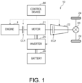
- Fig. 1 is a block diagram illustrating a schematic configuration of a hybrid vehicle 10 according to this embodiment.
- the vehicle 10 includes an internal combustion engine 1, a motor 21, an automatic transmission 22, a clutch CL1, a differential device 23, drive wheels 24, an inverter 25, a battery 26, and a control device 80. Both the engine 1 and the motor 21 can provide a travel driving force to the drive wheels 24.
- the engine 1 is an internal combustion engine which generates driving force by combusting fuel.
- the engine 1 of this embodiment may be a four-cycle diesel engine which uses light oil, or diesel fuel, as fuel.
- the engine 1 may also be a gasoline engine which uses gasoline as its primary fuel.
- the motor 21 may be, for example, a three-phase AC (alternating current) synchronous motor-generator which generates a driving force by receiving power supplied from the battery 26. During deceleration of the vehicle 10, the motor 21 performs a regenerative operation in which power is generated by the rotational force transmitted from the drive wheels 24. In this case, a regenerative resistance corresponding to the power generated by the motor 21 acts on the drive wheels 24. The regenerative resistance serves as a regenerative braking force to decelerate the vehicle 10. The generated power by the motor 21 is charged to the battery 26 via the inverter 25.
- AC alternating current
- the engine 1 and the motor 21 may be connected to each other arranged in series via the clutch CL1.
- the motor 21 may be connected to a drive shaft of the drive wheels 24 via the automatic transmission 22 and the differential device 23. By this configuration, both the engine 1 and the motor 21 can drive the drive wheels 24 of the vehicle 10.
- the clutch CL1 connects or disconnects a crankshaft to or from a rotating shaft of the motor 21.
- the crankshaft is an output shaft of an engine body 2.
- the automatic transmission 22 may have a function of shifting and outputting the rotation of the output shaft of the engine 1 and the rotating shaft of the motor 21.
- the automatic transmission 22 may include an input shaft, a plurality of planetary gear mechanisms, a plurality of brake mechanisms, a plurality of clutch mechanisms, and an output shaft.
- the automatic transmission 22 may change a rotational speed of the rotating shaft by switching a transmission path of the rotational force inputted to the input shaft through operation of each of the mechanisms, and output it from the output shaft.
- the input shaft is connected to the rotating shaft of the motor 21.
- the output shaft may be connected to the differential device 23 either directly or indirectly via the drive shaft.
- the plurality of clutch mechanisms of the automatic transmission 22 can be broadly considered as a single clutch CL2, since they work together to realize or achieve a desired gear ratio. Therefore, when the clutch CL2 is disconnected (or disengaged, or released), torque transmission between the input shaft and the output shaft is interrupted.
- the vehicle 10 can travel in any of the following modes: a motor driving mode using only the driving force of the motor 21, a combined driving mode using the driving forces of both the motor 21 and the engine 1, and an engine driving mode using only the driving force of the engine 1.
- a required torque of the vehicle 10 is shared between an engine torque generated by the engine 1 and a motor torque generated by the motor 21.
- the combined driving mode generally aims at driving by the engine torque, but when the engine torque alone cannot meet the required torque, a motor assist operation compensates for the shortage with the motor torque.
- the term "motor assist operation” is also used for operation which, when engine braking is enhanced beyond a required deceleration rate, generates the motor torque to offset the enhanced engine braking.
- the battery 26 is a rechargeable secondary battery.
- the battery 26 may be a lithium-ion battery or a nickel-metal hydride battery, for example.
- the battery 26 may supply driving power to the motor 21 via e.g. the inverter 25 when the motor 21 generates the driving force, including during motor assist operations.
- the battery 26 is charged by receiving the power generated during the regenerative operation of the motor 21 via e.g. the inverter 25.
- the inverter 25 may convert three-phase AC power into DC (direct current) power and vice versa. Particularly, when the motor 21 generates the driving force, the inverter 25 may convert the DC power stored in the battery 26 into three-phase AC power and supply it to the motor 21. On the other hand, when the motor 21 generates the three-phase AC power, the inverter 25 may convert it into DC power and supply it to the battery 26.
- the control device 80 may comprehensively control the operations of the vehicle 10, including the engine 1, the motor 21, the inverter 25, the automatic transmission 22, and the clutch CL1, so that the vehicle 10 travels according to the driving conditions.
- the control device 80 may be configured based on a well-known microcomputer, and may be comprised of a CPU (Central Processing Unit) which executes various programs, and memory, such as ROM and RAM, for storing the programs and various data.
- the functional configuration of the control device 80 will be described later with reference to Fig. 3 .
- Fig. 2 is a system diagram illustrating an overall structure of the engine.
- the engine 1 illustrated in Fig. 2 may be a four-cycle diesel engine.
- the engine 1 may include the engine body 2, an intake passage 30 through which intake air flows into the engine body 2, an exhaust passage 40 through which exhaust gas discharged from the engine body 2 flows, an EGR (exhaust gas recirculation) device 50 which recirculates a portion of the exhaust gas from the exhaust passage 40 back to the intake passage 30, and an exhaust turbocharger 60 which boosts or supercharges the intake air flowing through the intake passage 30.
- the engine 1 is controlled by the control device 80.
- the engine body 2 has one cylinder or a plurality of cylinders 2a arranged orthogonally to the plane of Fig. 2 .
- the engine body 2 may include a cylinder block 3, a cylinder head 4, and a plurality of pistons 5.
- the cylinders 2a may be formed by the cylinder block 3 and the cylinder head 4. That is, a plurality of cylindrical spaces corresponding to the cylinders 2a are formed inside the cylinder block 3, and the cylinder head 4 is attached to an upper surface of the cylinder block 3, closing off these cylindrical spaces from their top.
- Each of the pistons 5 is accommodated within the cylinders 2a to be reciprocatably slidable.
- a combustion chamber C is formed above each piston 5 of the cylinders 2a.
- the combustion chamber C may be a space defined by a lower surface of the cylinder head 4, a cylinder liner forming a side circumferential surface of the cylinder 2a, and a crown surface of the piston 5.
- the combustion chamber C may receive fuel injected from an injector 9, which will be described later.
- the piston 5 receives combustion energy of the fuel supplied to the combustion chamber C, and reciprocates in an up-and-down direction of the engine.
- a crankshaft 7, which is the output shaft of the engine body 2, may be provided below the piston 5 and in a lower part of the cylinder block 3.
- the crankshaft 7 may be coupled to each piston 5 of the cylinder 2a via a connecting rod 8, and rotates around its central axis in response to the reciprocating motion of the pistons 5.
- the cylinder block 3 may be equipped with a crank angle sensor SN1 and/or a water temperature sensor SN2.
- the crank angle sensor SN1 detects a crank angle which is a rotational angle of the crankshaft 7, and/or an engine speed which is a rotational speed of the crankshaft 7. Based on a detection result of the crank angle sensor SN1, a vehicle speed and acceleration of the vehicle 10 can be calculated.
- the water temperature sensor SN2 detects a temperature of a coolant circulating inside the cylinder block 3 and/or the cylinder head 4 (i.e., an engine water temperature).
- the injector 9 may be attached to the cylinder head 4.
- the injector 9 supplies the fuel to the combustion chamber C of each cylinder 2a.
- the injector 9 may be attached to the cylinder head 4 so that its tip part is exposed to the combustion chamber C.
- the tip part of the injector 9 may be formed with a plurality of nozzles through which the fuel is injected. The fuel injected from each nozzle combusts in the combustion chamber C at a high temperature and a high pressure due to self-ignition caused by the compression of the piston 5.
- the cylinder head 4 may be formed with intake ports 11 and exhaust ports 12.
- the intake ports 11 connect the combustion chambers C of the respective cylinders 2a with the intake passage 30.
- the exhaust ports 12 connect the combustion chambers C of the respective cylinders 2a with the exhaust passage 40.
- the intake port 11 of each cylinder 2a may be provided with an intake valve 13, and the exhaust port 12 of each cylinder 2a may be provided with an exhaust valve 14.
- the cylinder head 4 may be equipped with an intake valve mechanism 15 and an exhaust valve mechanism 16.
- the intake valve mechanism 15 may open and/or close the intake valve 13 in synchronization with the rotation of the crankshaft 7.
- the exhaust valve mechanism 16 may open and/or close the exhaust valve 14 in synchronization with the rotation of the crankshaft 7.
- the intake valve 13 may periodically open and/or close an opening of the intake port 11 on the combustion chamber C side in response to the operation of the intake valve mechanism 15.
- the exhaust valve 14 may periodically open and/or close an opening of the exhaust port 12 on the combustion chamber C side in response to the operation of the exhaust valve mechanism 16.
- the intake passage 30 may introduce intake air into the combustion chamber C of each cylinder 2a.
- the intake passage 30 may have an intake manifold 30a and a surge tank 30b in its downstream side section close to the engine body 2.
- the surge tank 30b provides an expanded space to equalize an introduction amount of intake air into each cylinder 2a.
- the intake manifold 30a may include a plurality of branch pipes connecting the surge tank 30b to the intake ports 11 of the cylinders 2a.
- An air cleaner 31, an intercooler 32, and an intake shutter valve 33 may be arranged sequentially in the intake passage 30 upstream of the surge tank 30b.
- the air cleaner 31 is a filter which removes foreign matter from the intake air.
- the intercooler 32 is a heat exchanger which cools the intake air compressed by the exhaust turbocharger 60.
- the intake shutter valve 33 may be a butterfly valve which is installed in the intake passage 30 to throttle a flow rate of the intake air.
- the intake passage 30 may be equipped with an air flow sensor SN3, an intake pressure sensor SN4, and an intake temperature sensor SN5.
- the air flow sensor SN3 detects the flow rate of the intake air introduced into the engine body 2, and may be positioned in the intake passage 30 downstream of the air cleaner 31.
- the intake pressure sensor SN4 detects a pressure of the intake air introduced into the engine body 2, and may be disposed at the surge tank 30b.
- the intake temperature sensor SN5 detects the temperature of the intake air, and may be disposed downstream of the intercooler 32.
- the exhaust passage 40 discharges outside the exhaust gas from the combustion chambers C of the cylinders 2a.
- the exhaust passage 40 may have an exhaust manifold 40a in its upstream side section closer to the engine body 2.
- the exhaust manifold 40a may include a plurality of branch pipes which communicate with the exhaust ports 12 of the cylinders 2a and an exhaust converging section where these branch pipes converge.
- One or a plurality of catalysts for removing various harmful components within the exhaust gas may be arranged in the exhaust passage 40 downstream of the exhaust manifold 40a.
- an oxidation catalyst 41 a DPF (Diesel Particulate Filter) 42
- an SCR (Selective Catalytic Reduction) catalyst 43 a slip catalyst 44 are arranged in this order from the upstream of the exhaust gas flow.
- a urea injector 45 and/or a mixing plate 47 may be arranged between the DPF 42 and the SCR catalyst 43 in the exhaust passage 40
- the oxidation catalyst 41 oxidizes CO and HC within the exhaust gas to render them harmless.
- the oxidation catalyst 41 includes a porous carrier and catalyst substances, such as platinum or palladium, supported on the carrier.
- the DPF 42 collects particulate matters, such as soot contained, within the exhaust gas.
- the DPF 42 may include catalyst substances, such as platinum, for burning soot under a high-temperature condition during filter regeneration.
- the SCR catalyst 43 reduces NO x in the exhaust gas to render it harmless.
- the SCR catalyst 43 may include a porous carrier and catalyst substances, such as vanadium, tungsten, or zeolite, supported on the carrier.
- the SCR catalyst 43 holds ammonia produced from urea water.
- the SCR catalyst 43 uses this ammonia as a reducing agent in a chemical reaction to convert NO x in the exhaust gas into N 2 and H 2 O.
- the slip catalyst 44 is an oxidative catalyst for oxidizing ammonia slipped from the SCR catalyst 43 which flew downstream without being used for the reduction of NO x .
- the slip catalyst 44 may have a similar structure to the oxidation catalyst 41, for example.
- the urea injector 45 supplies urea water to the SCR catalyst 43.
- the urea injector 45 may inject the urea water made by dissolving highly pure urea, into the exhaust passage 40.
- the urea injector 45 receives the urea water from a tank 46 storing the urea water via a supply pipe 46a.
- the mixing plate 47 sends the urea water injected by the urea injector 45 to the downstream SCR catalyst 43 while evenly dispersing it.
- the mixing plate 47 may be a plate-like member dividing the exhaust passage 40 into front and rear sections, and has a plurality of openings to stir the exhaust gas.
- this temperature range may be a high-temperature range exceeding 150°C. If the temperature of the SCR catalyst 43 drops below a given high-temperature range, the NO x removal performance of the SCR catalyst 43 may degrade.
- the removal performance of the SCR catalyst 43 may degrade, for example, immediately after a cold start of the engine 1 or when the engine 1 undergoes a fuel-cut operation for a long period of time while driving on a long downhill. Note that, also for a three-way catalyst used when the engine 1 a gasoline engine, its exhaust emission control performance may degrade when a temperature of the catalyst drops.
- the engine 1 tends to be stopped for a longer period of time, making the temperature of the SCR catalyst 43 to drop easily.
- the temperature of the SCR catalyst 43 drops.
- a control is performed in which the temperature of the SCR catalyst 43 is maintained while ensuring that an SOC (state of charge) of the battery 26 does not exceed its upper limit. This control will be described in more detail later.
- the exhaust passage 40 may be provided with an exhaust O 2 sensor SN6, an NO x concentration sensor SN7, and an exhaust temperature sensor SN8.
- the exhaust O 2 sensor SN6 may be disposed in the exhaust passage 40 upstream of the oxidation catalyst 41, and measures an oxygen amount within the exhaust gas.
- the NO x concentration sensor SN7 is disposed between the DPF 42 and the SCR catalyst 43, and detects a concentration of NO x within the exhaust gas.
- the exhaust temperature sensor SN8 may be disposed at a position downstream of the NO x concentration sensor SN7 and immediately upstream of the SCR catalyst 43, and measures the temperature of the exhaust gas. The detected value of the exhaust temperature sensor SN8 is used to estimate the temperature of the SCR catalyst 43.
- the exhaust turbocharger 60 uses the exhaust gas discharged from the combustion chamber C to boost air supplied to the combustion chamber C.
- the exhaust turbocharger 60 may include a compressor 61, and a turbine 62, and optionally a VGT (variable geometry turbocharger) actuator 63.
- the compressor 61 is disposed in the intake passage 30 between the air cleaner 31 and the intercooler 32.
- the turbine 62 may be disposed in the exhaust passage 40 upstream of the oxidation catalyst 41.
- the exhaust gas discharged from the engine body 2 is introduced to the turbine 62 to rotatably drive the turbine 62.
- the compressor 61 rotates in connection with the turbine 62 to pump the intake air downstream. In other words, boosting (or supercharging) in which the intake air inside the intake passage 30 is sent to the engine body 2 while being compressed is performed.
- the turbine 62 may be of a VGT type equipped with a variable vane mechanism which adjusts a flow rate of the exhaust gas (turbine volume).
- the variable vane mechanism includes a plurality of nozzle vanes of which angles are adjustable. Adjusting the angles of these nozzle vanes changes the flow rate of the exhaust gas.
- the VGT actuator 63 adjusts the angles of the nozzle vanes.
- the EGR device 50 may include an EGR passage 51, an EGR cooler 52, and an EGR valve 53.
- the EGR passage 51 recirculates the exhaust gas from the exhaust passage 40 to the intake passage 30.
- the EGR passage 51 may connect a section of the exhaust passage 40 upstream of the turbine 62 with a portion of the intake passage 30 between the intake shutter valve 33 and the surge tank 30b.
- the EGR cooler 52 cools EGR gas recirculated through the EGR passage 51 to the intake passage 30.
- the EGR valve 53 adjusts a recirculation flow rate of the EGR gas.
- Fig. 3 is a functional block diagram illustrating a control system of the vehicle 10.
- the vehicle 10 includes the control device 80 which may comprehensively control various parts of the vehicle 10, as well as the engine 1 and the motor 21.
- Various sensor data may be inputted into the control device 80.
- information detected by at least one of the crank angle sensor SN1, the water temperature sensor SN2, the air flow sensor SN3, the intake pressure sensor SN4, the intake temperature sensor SN5, the exhaust O 2 sensor SN6, the NO x concentration sensor SN7, and the exhaust temperature sensor SN8, such as the crank angle, the engine speed, the engine water temperature, the intake flow rate, the intake pressure, the intake temperature, the exhaust oxygen level, the NO x concentration, and the exhaust temperature, may be sequentially inputted to the control device 80.
- the vehicle 10 may also have an outdoor temperature sensor SN9 and/or an accelerator opening sensor SN10.
- the outdoor temperature sensor SN9 measures an external ambient temperature around the vehicle 10.
- the accelerator opening sensor SN10 detects the degree of opening of the accelerator pedal operated by a vehicle driver, i.e., the accelerator opening.
- the accelerator opening information may be used to determine the requested torque for the engine system, including engine 1 and motor 21.
- the information detected by the outdoor temperature sensor SN9 and the accelerator opening sensor SN10 may also sequentially inputted to the control device 80.
- the control device 80 controls e.g. the various parts of the vehicle 10 based on the input information from the sensors SN1 to SN10.
- the control device 80 may be electrically connected to the injector 9, the intake shutter valve 33, the EGR valve 53, the urea injector 45, the VGT actuator 63, the automatic transmission 22, and the inverter 25.
- the control device 80 may output control signals generated based on the input information from the sensors SN1 to SN10 to these electrically-connected components.
- the control device 80 may operate to functionally include at least one of an engine controller 81, a motor controller 82, a requested torque calculator 83, an engine torque calculator 84, a motor torque calculator 85, a catalyst temperature estimator 86, an SOC calculator 87, a memory 88, and a deceleration controller 89 (controller) by executing specified program(s).
- the engine controller 81 may control the operation of the engine 1.
- the engine controller 81 may determine an intake amount, a fuel injection amount, etc., so that the engine 1 outputs a final set engine torque in response to various situations, and controls the injector 9, the intake shutter valve 33, etc.
- the motor controller 82 may control the inverter 25 so that the motor 21 outputs a final set motor torque.
- the requested torque calculator 83 may calculate the requested torque of the vehicle 10 based on an accelerator operation by a vehicle driver, i.e., based on the accelerator opening detected by the accelerator opening sensor SN10. In the hybrid vehicle 10 of this embodiment, the requested torque is shared between the engine torque generated by the engine 1 and the motor torque generated by the motor 21.
- the engine torque calculator 84 may calculate the engine torque to be generated by the engine 1, e.g. based on a driving condition and the requested torque.
- the motor torque calculator 85 calculates the motor torque to be generated by the motor 21, based on the driving condition and the requested torque.
- the catalyst temperature estimator 86 may perform computational processing in which the temperature of the SCR catalyst 43 is estimated.
- a heat input amount to the SCR catalyst 43 is calculated based on the temperature of the exhaust gas at a position immediately before the SCR catalyst 43 which is detected by the exhaust temperature sensor SN8, and the flow rate of the exhaust gas.
- the flow rate of the exhaust gas can be estimated from the intake flow rate detected by the air flow sensor SN3, the opening degree of the EGR valve 53, etc.
- a heat release amount from the SCR catalyst 43 may be calculated based on the vehicle speed derived from the crank angle sensor SN1 and the external ambient temperature detected by the outdoor temperature sensor SN9.
- a temperature Ts of the SCR catalyst 43 may be calculated based on the heat input amount, the heat release amount, and a heat volume of the SCR catalyst 43 stored in advance. Note that a sensor which directly measures the temperature of the SCR catalyst 43 may be installed instead of the catalyst temperature estimator 86.
- the SOC calculator 87 may estimate a current SOC of the battery 26.
- the SOC calculator 87 may continuously add up charge/discharge current values detected by a current detector installed in a charge-discharge circuit of the battery 26, to calculate an accumulated charge amount.
- the accumulated electrical charge amount may be calculated by adding the charged power during the charging operation, and subtracting the released power during the discharging operation.
- the SOC of the battery 26 may be calculated based on the accumulated charge amount.
- the memory 88 may store setting value(s) and data necessary for the operations of the control device 80.
- the memory 88 may store SOC-related setting information (e.g., first and second given values of the SOC), such as the heat volume of the SCR catalyst 43, a suitable operating temperature of the SCR catalyst 43, and an upper SOC limit of the battery 26 (e.g., 80%).
- the deceleration controller 89 may perform a temperature maintenance control in which the temperature of the SCR catalyst 43 is maintained within a given range, particularly a given high temperature range while ensuring that the SOC of the battery 26 does not exceed its upper limit, during specific deceleration of the vehicle 10, such as when driving on a long downhill.
- the deceleration controller 89 may perform at least the following first or second control as the temperature maintenance control.
- Fig. 4 is a chart illustrating a relationship between a fuel injection pattern by the injector 9 of the engine 1 and an in-cylinder heat generation rate (dQ/d ⁇ ).
- a heat generation rate characteristic H1 illustrated in Fig. 4 indicates a heat generation rate of typical combustion performed in the engine body 2 during a normal operation.
- the heat generation rate characteristic H1 has a large peak at a crank angle slightly retarded from TDC (Top Dead Center), indicating that a higher engine torque can be generated.
- a fuel injection pattern A1 illustrated in the lower part of Fig. 4 may be a split injection pattern performed by the injector 9 during the normal operation.
- the injection may be mainly performed in a latter half of the compression stroke and near the TDC.
- Another heat generation rate characteristic H2 illustrated in Fig. 4 indicates the heat generation rate of combustion performed in the engine body 2 during the temperature maintenance control.
- the heat generation rate characteristic H2 shows a plurality of small peaks on expansion stroke after TDC.
- the heat generation rate characteristic H2 indicates that combustion with a small heat generation rate continues from the TDC to an intermediate range of the expansion stroke.
- the engine torque is not substantially generated.
- a fuel injection pattern A2 may be a split injection pattern performed by the injector 9 during the temperature maintenance control.
- a plurality of fuel injections may be performed from near the TDC to the intermediate range of the expansion stroke.
- the fuel injection near the TDC is intended to raise the in-cylinder temperature so that the fuel injected in the intermediate range of the expansion stroke combusts without causing misfire, and is not intended to generate an engine torque.
- the deceleration controller 89 may operate the VGT actuator 63 to adjust the angles of the nozzle vanes so that the flow rate of the exhaust gas increases.
- the rotation speed of the compressor 61 and the boosting pressure are increased.
- the fuel injection is performed on the expansion stroke where the piston 5 descends, the fuel tends to adhere or attach to an inner wall of the cylinder 2a, i.e., the cylinder liner. In this case, the fuel may enter an oil pan of the cylinder block 3, potentially causing fuel dilution of the engine oil.
- Increasing the boosting pressure shortens a traveling distance of the fuel injected into the cylinder 2a, resulting in suppression of the fuel adhesion to the cylinder liner.
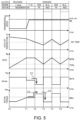
- Fig. 5 is a time chart illustrating the operations of the engine and the motor during the temperature maintenance control in the downhill driving mode of the vehicle.
- Fig. 5 illustrates, in the order from the top, charts of the transmission speed, the catalyst temperature, the SOC, bmep (brake mean effective pressure), and the motor torque.
- a table indicating operating states of the clutch CL1, the engine 1, and the motor 21 is also provided above the chart.
- the transmission speed (rpm) indicates the rotational speed of the shaft, e.g. the output shaft, of the automatic transmission 22.
- the transmission speed the rotational speed of the motor 21 (mot_rev).
- mot_rev the engine speed (NE).
- the catalyst temperature (°C) is the temperature of the SCR catalyst 43 obtained by the catalyst temperature estimator 86.
- the SOC is the remaining charge of the battery 26 obtained by the SOC calculator 87.
- SOC 80% is exemplified as the first given value, which is the SOC upper limit
- SOC 75% is exemplified as the second given value, which is a threshold for switching the battery 26 from the discharge mode to the charge mode in the temperature maintenance control.
- the first and second given values can be appropriately set according to the characteristics of the battery 26, control philosophy, etc.
- bmep (Pa) is an index indicating a pressure of the engine brake of the engine 1.
- Nm indicates the torque generated by the motor 21 and regenerative braking.
- the regenerative braking occurs in the positive region. In the positive region, the motor torque is generated.
- Time T0 is a certain time point at which the downhill driving is already ongoing and the above fourth control is performed.
- the catalyst temperature is still higher than the set temperature, and the SOC is below the first given value (80%).
- the vehicle 10 is decelerating with the regenerative braking.
- the clutch CL1 is released, and the engine 1 is stopped (i-stop).
- Only the motor 21 which is coupled to the drive shaft of the drive wheels 24 via the automatic transmission 22 generates braking force according to the regenerative resistance.
- the catalyst temperature drops since the engine 1 is in the stopped state, and the SOC increases as the motor 21 performs the regenerative operation.
- Time T1 is a time point at which the SOC reaches the first given value and the control mode shifts from the fourth control to the third control.
- the catalyst temperature is still above the set temperature.
- the deceleration controller 89 engages the clutch CL1 and rotates the engine 1 in the fuel-cut state (F/C).
- the engine braking occurs as indicated by the chart of the bmep.
- the deceleration controller 89 controls the inverter 25 to stop the regenerative operation, preventing an increase in the SOC. Therefore, the vehicle 10 decelerates through the engine braking provided by the motoring of the engine 1.
- the catalyst temperature continues to drop while the SOC is maintained at the first given value.
- Time T2 is a time point at which the SOC is at the first given value and the catalyst temperature drops to the set temperature.
- the deceleration controller 89 may perform the above first control. Particularly, the deceleration controller 89 increases the engine resistance so that the deceleration exceeds the requested deceleration calculated by the requested torque calculator 83.
- a second engine resistance above a first engine resistance set at time T1 is set, and the engine braking is enhanced (illustrated as "EEB (Enhanced Engine Braking)" in the table of Fig. 5 ).
- the deceleration controller 89 causes the motor 21 to perform the motor assist operation according to the increased engine resistance (illustrated as "PA (Power Assist)" in the table of Fig. 5 ).
- the deceleration controller 89 instructs the motor controller 82 to supply drive power to the motor 21 via the inverter 25 so that the motor 21 generates driving force.
- the enhanced engine braking is offset by the motor torque generated based on the motor assist operation, maintaining drivability.
- the SOC of the battery 26 is consumed, creating a state where the regenerative braking is available.
- the first control is performed first to discharge the battery 26 in order to provide some margin for the SOC.
- the catalyst temperature further drops while the SOC decreases from the first given value.
- one example of the control of increasing the engine resistance may be a control of decreasing the in-cylinder pressure within the cylinder 2a to be lower than the surrounding environment to increase a motional resistance to the piston 5.
- operating the intake shutter valve 33 or controlling the opening timing of the intake valve 13 may be included. Closing the intake shutter valve 33 may create a semi-sealed state inside the cylinder 2a, increasing the motional resistance to the piston 5. Creating a negative overlap period where both the intake valve 13 and the exhaust valve 14 are closed by retarding the opening timing of the intake valve 13 seals cylinder 2a, and can increase the motional resistance to the piston 5.
- Increasing the motional resistance to the piston 5 leads to the increased engine resistance, enhancing the engine braking.
- control of increasing the engine resistance may be a control of downshifting the automatic transmission 22.
- the automatic transmission 22 is downshifted by one or more gears from the current gear to increase the engine speed. Increasing the engine speed makes it easier to increase the engine resistance.
- Time T3 is a time point at which the SOC decreases to the second given value (75%) and the catalyst temperature drops to below the set temperature.
- the deceleration controller 89 performs the above second control.
- the deceleration controller 89 may instruct the engine controller 81 to perform combustion to maintain the temperature of the SCR catalyst 43.
- the engine controller 81 may cause combustion to only heat the catalyst, by controlling the injector 9 to perform a fuel injection in the fuel injection pattern A2 of Fig. 4 .
- the combustion state may be controlled so that an engine load becomes zero (illustrated as "N/L" in the table of Fig. 5 ). By this control, the engine braking is lost as indicated by the bmep chart.
- the motor 21 can perform the regenerative operation.
- the motor 21 may be controlled to perform the regenerative operation by using the margin of the SOC, which is the difference between the first given value and the second given value, to generate the regenerative braking.
- the deceleration controller 89 may instruct the motor controller 82 to generate the regenerative resistance to compensate for the loss of the engine braking. In other words, the deceleration equivalent to the engine braking is created by the regenerative braking.
- the first control is performed even if the catalyst temperature is below the set temperature. Then, when the SOC decreases to the second given value as a result of the first control, the control mode is switched to the second control.
- the cooperative control is performed in which the first control is first performed to discharge the battery 26 and create the margin for the SOC, and then the second control is performed to raise the temperature of the SCR catalyst 43.
- An excessive deceleration torque generated by enhancing the engine braking in the first control can be offset by the motor torque gained from the motor assist operation.
- the second control following the first control can create the deceleration equivalent to the engine braking through the regenerative braking. Therefore, drivability can be maintained without causing discomfort to the vehicle driver during deceleration.
- Time T4 is a time point at which the SOC recovers to the first given value (80%) while the vehicle 10 continues to decelerate.
- the deceleration controller 89 switches the control mode from the second control to the first control.
- the deceleration controller 89 may generate the engine braking by the enhanced second engine resistance, and generates the regenerative braking force to offset the enhanced engine braking force.
- drivability is maintained while suppressing the increase of the SOC.
- the deceleration controller 89 may switche the control mode from the first control to the second control. Thereafter, during the deceleration of the vehicle 10, the first and second controls are repeated according to the SOC of the battery 26. Therefore, even while driving on a long downhill, the temperature of the SCR catalyst 43 can be maintained without overcharging the battery 26.
- Fig. 6 is a flowchart illustrating one example of a deceleration control in the downhill driving mode of the vehicle 10 by the control device 80. While the vehicle 10 drives, the control device 80 may determine whether the vehicle 10 is on a downhill (Step S1). This determination can be made based on measured data, such as the accelerator opening detected by the accelerator opening sensor SN10, the vehicle speed and acceleration based on the crank angle sensor SN1, and/or a decrease in the intake pressure due to the vehicle traveling by its own weight which is detected by the intake pressure sensor SN4.
- the control device 80 may execute a different driving mode according to an engine control algorithm based on the detection results of the various sensors (Step S2). Conversely, if it is determined that the vehicle is driving downhill (YES at Step S1), the deceleration controller 89 of the control device 80 may stop the engine 1 via the engine controller 81 (Step S3). Further, the deceleration controller 89 may release the clutch CL1 and decelerates the vehicle 10 by using the regenerative braking of the motor 21 (Step S4). This state at Step S4 corresponds to the state at time T0 in the time chart of Fig. 5 .
- the deceleration controller 89 may engage the clutch CL1 and connects the engine 1 to the drive shaft of the drive wheels 24 (Step S6). Note that the deceleration controller 89 may perform the motoring in which the engine is rotated in the fuel-cut state without supplying the fuel from the injector 9 (Step S7). This state at Step S7 corresponds to the state at time T1 in the time chart of Fig. 5 .
- the deceleration controller 89 may determine whether the temperature of the SCR catalyst 43 (hereinafter referred to as "SCR temperature”) is below the given setting temperature based on the output value of the catalyst temperature estimator 86 (Step S8). If the SCR temperature is below the setting temperature (Step S8: YES), the deceleration controller 89 may perform the catalyst temperature maintenance control to maintain the temperature of the SCR catalyst 43 (Step S11). Conversely, if the SCR temperature is the setting temperature or above (Step S8: NO), the deceleration controller 89 continues the motoring from Step S7.
- SCR temperature the temperature of the SCR catalyst 43
- Step S5 the SOC is below the first given value
- Step S9 the deceleration controller 89 may determine whether the SCR temperature is below the setting temperature (Step S9). If the SCR temperature is the setting temperature or above (Step S9: NO), both the SOC and the SCR temperature have margins. Therefore, the process may return to Step S4, where the deceleration of the vehicle 10 by using the regenerative braking continues. Conversely, if the SCR temperature is below the setting temperature (Step S9: YES), the deceleration controller 89 may perform the control of engaging the clutch CL1 to connect the engine 1 to the drive shaft of the driven wheels 24 (Step S10). The deceleration controller 89 then performs the catalyst temperature maintenance control (Step S11).
- Fig. 7 is a flowchart illustrating one example of the catalyst temperature maintenance control by the deceleration controller 89.
- the deceleration controller 89 determines whether the SOC of the battery 26 is the first given value or above (Step S21). If the SOC is the first given value or above (Step S21: YES), the deceleration controller 89 decides to perform the above first control (Step S22). If the SOC is below the first given value (Step S21: NO), the deceleration controller 89 may decide to perform the above second control (Step S23).
- the deceleration controller 89 may form a deceleration torque greater than the requested deceleration derived by the request torque calculator 83 (Step S24). Specifically, the deceleration controller 89 may execute one or more of the following measures: closing the intake shutter valve 33; retarding the opening timing of the intake valve 13; and downshifting the gear of the automatic transmission 22. Thus, the engine resistance is increased and the engine braking is enhanced.
- An arrow C1 of Fig. 5 corresponds to the enhancement of the engine braking at Step S24.
- the deceleration controller 89 causes the motor 21 to perform the motor assist operation (Step S25).
- the motor torque calculator 85 may calculate the motor torque corresponding to the increased engine resistance described above.
- the deceleration controller 89 instructs the motor controller 82 to control the motor 21 to generate the calculated motor torque.
- An arrow C2 of Fig. 5 corresponds to the generation of the motor torque at Step S25. This control cancels out the enhanced engine braking with the motor torque, and thus the vehicle driver does not feel discomfort from a sudden change in deceleration.
- the timing when these controls at Steps S24 and S25 start corresponds to time T2 of Fig. 5 .
- the deceleration controller 89 may cause the injector 9 to perform the fuel injection which causes the engine 1 to perform the no-load combustion, as illustrated in the fuel injection pattern A2 of Fig. 4 (Step S27).
- the deceleration controller 89 causes the motor torque calculator 85 to calculate the required motor torque to compensate for the deceleration torque corresponding to the current requested deceleration by using the regenerative braking.
- the deceleration controller 89 causes the motor 21 to perform the regenerative operation to generate the regenerative torque corresponding to the calculated motor torque (Step S28).
- Step S27 and S28 start corresponds to time T3 of Fig. 5 .
- An arrow C3 of Fig. 5 corresponds to the transition from the motor assist operation to the regenerative operation at Step S28. If no deceleration end is detected (Step S29: NO), the process may return to Step S21 and repeats. If a deceleration end is detected (Step S29: YES), the deceleration controller 89 may end the catalyst temperature maintenance control.
Landscapes
- Engineering & Computer Science (AREA)
- Chemical & Material Sciences (AREA)
- Combustion & Propulsion (AREA)
- Transportation (AREA)
- Mechanical Engineering (AREA)
- Automation & Control Theory (AREA)
- Electrical Control Of Air Or Fuel Supplied To Internal-Combustion Engine (AREA)
- Hybrid Electric Vehicles (AREA)
- Exhaust Gas After Treatment (AREA)
- Electric Propulsion And Braking For Vehicles (AREA)
Abstract
Description
- The present invention relates to a control device of a vehicle, particularly a hybrid vehicle including both an engine and a motor as driving sources.
- Hybrid vehicles equipped with an engine formed with a combustion chamber and an electric motor as driving sources, are becoming widespread. An exhaust system of the engine is provided with a catalytic converter which neutralizes exhaust gas. For diesel engines, an exhaust emission control device including an SCR (Selective Catalytic Reduction) catalyst for removing NOx may be used. It is crucial to maintain the catalyst at an appropriate operating temperature to keep it active.
WO2020/095536A1 discloses a control device which, if a catalyst temperature in a hybrid vehicle is below a given temperature, performs a catalyst temperature increase control while performing a motoring operation in which an engine is rotated in a fuel-cut state. - In the hybrid vehicles, during deceleration, regenerative braking based on a regenerative resistance of the motor may be used in a state where the engine is disconnected from the drivetrain. Here, the power generated by the motor is stored in a battery. Consequently, in a driving scenario in which the vehicle decelerates, for example, on a long downhill, an SOC (state of charge) of the battery may reach its upper limit. In such a case, the engine is connected to the drivetrain and put into a motoring state, allowing the use of engine braking. However, since the engine may remain inactive for a relatively long period, the catalyst temperature may drop below a set temperature. In this situation, it is effective to induce combustion inside engine cylinders to the extent that it maintains the catalyst temperature. However, if compensating for the loss of engine braking due to combustion with regenerative braking is attempted, the SOC may exceed its upper limit. Thus, an issue may arise where the combustion for maintaining the catalyst temperature cannot be performed.
- One purpose of the present invention is to provide a vehicle control device, which maintains a temperature of a catalyst of an exhaust emission control device in a hybrid vehicle, while also considering SOC of a battery.
- A control device of a vehicle according to the present invention is defined in
claim 1. Particularly, the vehicle includes an engine having an exhaust system provided with a combustion chamber and a catalyst, and configured to generate a driving force to operate drive wheels of the vehicle, a motor able to operate the drive wheels, and a battery which supplies driving power to the motor in a motor assist operation in which the motor operates the drive wheels, and is charged in a regenerative operation in which the motor generates power. The control device includes a controller which controls operation of the vehicle. When the vehicle decelerates, the controller performs one of a first control in which an engine resistance is increased to obtain a higher deceleration than a requested deceleration and the motor assist operation is performed according to the increase of the engine resistance, when a state of charge (SOC) of the battery is a first given value or above; and a second control in which a combustion state of the engine is controlled to raise a temperature of the catalyst e.g. by injecting fuel in an expansion stroke, and the regenerative operation is performed, when the SOC of the battery is a second given value that is below the first given value. - According to this aspect, one of the first control and the second control is performed according to the SOC of the battery. In the first control, while the engine resistance is increased so that engine braking is enhanced, the motor assist operation is performed so that the power of the battery is consumed, that is, the SOC is decreased. On the other hand, in the second control, the engine is controlled to perform combustion to maintain the temperature of the catalyst. Further, the motor is controlled to perform the regenerative operation by using margin of the SOC, which is a difference between the first given value and the second given value, to generate the regenerative braking. Thus, both suppression of battery overcharge and maintenance of the catalyst temperature can be achieved.
- In the above control device of the vehicle, the controller may perform the first control and/or the second control when the temperature of the catalyst is below a set temperature during deceleration of the vehicle, and switch the control mode to the second control when the SOC drops to the second given value by performing the first control.
- According to this configuration, even when the catalyst temperature is below the set temperature, the cooperative control is performed in which the first control is first performed to discharge the battery and create the margin for the SOC, and then the second control is performed to raise the temperature of the catalyst. An excessive deceleration torque generated by enhancing the engine braking in the first control can be offset by the motor torque gained from the motor assist operation. Additionally, the second control following the first control can create the deceleration equivalent to the engine braking loss through the regenerative braking. Therefore, drivability can be maintained without causing discomfort to a vehicle driver during deceleration.
- In the above control device of the vehicle, the vehicle may further include a clutch which changes a torque transmission state between an output shaft of the engine and a drive shaft of the drive wheels. The controller may perform a third control in which the clutch is engaged and the engine is operated in a fuel-cut state to generate a first engine resistance, when the SOC is the first given value or above and the temperature of the catalyst is above the set temperature in a state where the clutch is released to disconnect the engine from the drive shaft and the vehicle decelerates by a regenerative resistance generated by the regenerative operation of the motor, and the first control using a second engine resistance that is above the first engine resistance, when the temperature of the catalyst decreases to be below the set temperature during the third control.
- According to this configuration, when the SOC is the first given value or above in a state where the vehicle decelerates by the regenerative braking, the third control in which motoring is performed to generate the engine braking is performed. Thus, the increase of the SOC can be suppressed. Further, when the catalyst temperature becomes below the set temperature during the third control, the first control is performed using the increased engine resistance to enhance the engine braking. This increase of the engine braking is offset by the motor assist operation. Thus, drivability is maintained while decreasing the SOC to create a state where the second control which performs combustion to raise the catalyst temperature can be performed thereafter.
- In the above control device of the vehicle, after the control mode is switched to the second control, the controller may switch the control mode to the first control when the SOC is the first given value or above while the vehicle continues to decelerate.
- According to this configuration, during the deceleration of the vehicle, the first and second controls are repeated according to the SOC of the battery. Therefore, even while driving on a long downhill, the catalyst temperature can be maintained without overcharging the battery.
- In the above control device of the vehicle, in the second control, the controller may control the combustion state so that a load of the engine becomes zero.
- According to this configuration, in the second control, the engine performs combustion to only heat the catalyst, without generating a traveling torque. Therefore, the vehicle driver does not have a sensation of acceleration during the deceleration of the vehicle.
- In the above control device of the vehicle, the controller may set the regenerative resistance of the motor in the second control so as to compensate for a loss of the engine resistance caused by switching from the first control to the second control.
- According to this configuration, the deceleration equivalent to the engine braking lost due to termination of the first control can be compensated with the regenerative braking. Therefore, even when the control mode is switched from the first control to the second control, the vehicle driver is not given discomfort during deceleration.
- In the above control device of the vehicle, the engine may be provided with a piston and a cylinder, and, as the control of increasing the engine resistance, the controller may perform a control of increasing a resistance of the piston by decreasing a pressure inside the cylinder to be lower than that of a surrounding environment. According to this configuration, the engine resistance can be increased easily by adjusting the in-cylinder pressure.
- In the above control device of the vehicle, the vehicle may include a transmission arranged between output shafts of the engine and the motor, and the drive shaft of the drive wheels. As the control of increasing the engine resistance, the controller may perform a control of downshifting the gear of the transmission. According to this configuration, the engine resistance can be increased easily by downshifting.
- In the above control device of the vehicle, as the control of raising the temperature of the catalyst, the controller may perform a fuel injection in or on expansion stroke of the engine.
- According to this configuration, it makes possible to perform combustion which does not substantially generate an engine torque. Therefore, the catalyst temperature can be maintained during deceleration without causing acceleration.
- In the above control device of the vehicle, the vehicle may include a booster, a supercharger, or a turbocharger which boosts or supercharges air to be supplied into the combustion chamber of the engine. The controller may control the booster, the supercharger, or the turbocharger to increase a boosting pressure or a pressure during the control of raising the temperature of the catalyst.
- When the fuel injection is performed in or on the expansion stroke, the injected fuel tends to adhere or attach to an inner wall of the cylinder. Increasing the boosting pressure shortens a traveling distance of the fuel injected into the cylinder, resulting in suppression of the fuel adhesion to the inner wall of the cylinder.
-
-
Fig. 1 is a block diagram schematically illustrating an overall structure of a hybrid vehicle to which a control device of the present invention is applied. -
Fig. 2 is a system diagram of an engine of the vehicle. -
Fig. 3 is a functional block diagram illustrating a control system of the vehicle. -
Fig. 4 is a chart illustrating a relationship between a fuel injection pattern of the engine and an in-cylinder heat generation rate. -
Fig. 5 is a time chart illustrating operations of the engine and a motor in a downhill driving mode of the vehicle. -
Fig. 6 is a flowchart illustrating an example of a deceleration control in the downhill driving mode of the vehicle by the control device of one embodiment. -
Fig. 7 is a flowchart illustrating an example of a catalyst temperature maintenance control by the control device of this embodiment. - Hereinafter, a vehicle control device according to one embodiment of the present invention is described with reference to the accompanying drawings. The vehicle controlled by the control device of this embodiment is a vehicle, particularly a hybrid vehicle, equipped with an engine formed with a combustion chamber and an electric motor as travel driving sources for operating drive wheels of the vehicle, and a catalyst in an exhaust system of the engine.
-
Fig. 1 is a block diagram illustrating a schematic configuration of ahybrid vehicle 10 according to this embodiment. Thevehicle 10 includes aninternal combustion engine 1, amotor 21, anautomatic transmission 22, a clutch CL1, adifferential device 23,drive wheels 24, aninverter 25, abattery 26, and acontrol device 80. Both theengine 1 and themotor 21 can provide a travel driving force to thedrive wheels 24. - The
engine 1 is an internal combustion engine which generates driving force by combusting fuel. Theengine 1 of this embodiment may be a four-cycle diesel engine which uses light oil, or diesel fuel, as fuel. Theengine 1 may also be a gasoline engine which uses gasoline as its primary fuel. - The
motor 21 may be, for example, a three-phase AC (alternating current) synchronous motor-generator which generates a driving force by receiving power supplied from thebattery 26. During deceleration of thevehicle 10, themotor 21 performs a regenerative operation in which power is generated by the rotational force transmitted from thedrive wheels 24. In this case, a regenerative resistance corresponding to the power generated by themotor 21 acts on thedrive wheels 24. The regenerative resistance serves as a regenerative braking force to decelerate thevehicle 10. The generated power by themotor 21 is charged to thebattery 26 via theinverter 25. - The
engine 1 and themotor 21 may be connected to each other arranged in series via the clutch CL1. Themotor 21 may be connected to a drive shaft of thedrive wheels 24 via theautomatic transmission 22 and thedifferential device 23. By this configuration, both theengine 1 and themotor 21 can drive thedrive wheels 24 of thevehicle 10. The clutch CL1 connects or disconnects a crankshaft to or from a rotating shaft of themotor 21. The crankshaft is an output shaft of anengine body 2. - The
automatic transmission 22 may have a function of shifting and outputting the rotation of the output shaft of theengine 1 and the rotating shaft of themotor 21. Theautomatic transmission 22 may include an input shaft, a plurality of planetary gear mechanisms, a plurality of brake mechanisms, a plurality of clutch mechanisms, and an output shaft. Theautomatic transmission 22 may change a rotational speed of the rotating shaft by switching a transmission path of the rotational force inputted to the input shaft through operation of each of the mechanisms, and output it from the output shaft. The input shaft is connected to the rotating shaft of themotor 21. The output shaft may be connected to thedifferential device 23 either directly or indirectly via the drive shaft. Note that the plurality of clutch mechanisms of theautomatic transmission 22 can be broadly considered as a single clutch CL2, since they work together to realize or achieve a desired gear ratio. Therefore, when the clutch CL2 is disconnected (or disengaged, or released), torque transmission between the input shaft and the output shaft is interrupted. - In a state where the clutch CL2 of the
automatic transmission 22 is connected (or engaged) and the clutch CL1 is disconnected, only the driving force generated by themotor 21 is transmitted to thedrive wheels 24 via theautomatic transmission 22. On the other hand, in a state where both the clutch CL1 and CL2 are connected, the driving forces of both theengine 1 and themotor 21 are transmitted to thedrive wheels 24. In this case, when themotor 21 does not generate the driving force, i.e., when no power is supplied to themotor 21, only the driving force generated by theengine 1 is transmitted to thedrive wheels 24. - By the above driving modes, the
vehicle 10 can travel in any of the following modes: a motor driving mode using only the driving force of themotor 21, a combined driving mode using the driving forces of both themotor 21 and theengine 1, and an engine driving mode using only the driving force of theengine 1. In the combined driving mode, a required torque of thevehicle 10 is shared between an engine torque generated by theengine 1 and a motor torque generated by themotor 21. For example, the combined driving mode generally aims at driving by the engine torque, but when the engine torque alone cannot meet the required torque, a motor assist operation compensates for the shortage with the motor torque. As will be explained later, in this embodiment, the term "motor assist operation" is also used for operation which, when engine braking is enhanced beyond a required deceleration rate, generates the motor torque to offset the enhanced engine braking. - The
battery 26 is a rechargeable secondary battery. Thebattery 26 may be a lithium-ion battery or a nickel-metal hydride battery, for example. Thebattery 26 may supply driving power to themotor 21 via e.g. theinverter 25 when themotor 21 generates the driving force, including during motor assist operations. Thebattery 26 is charged by receiving the power generated during the regenerative operation of themotor 21 via e.g. theinverter 25. - The
inverter 25 may convert three-phase AC power into DC (direct current) power and vice versa. Particularly, when themotor 21 generates the driving force, theinverter 25 may convert the DC power stored in thebattery 26 into three-phase AC power and supply it to themotor 21. On the other hand, when themotor 21 generates the three-phase AC power, theinverter 25 may convert it into DC power and supply it to thebattery 26. - The
control device 80 may comprehensively control the operations of thevehicle 10, including theengine 1, themotor 21, theinverter 25, theautomatic transmission 22, and the clutch CL1, so that thevehicle 10 travels according to the driving conditions. Thecontrol device 80 may be configured based on a well-known microcomputer, and may be comprised of a CPU (Central Processing Unit) which executes various programs, and memory, such as ROM and RAM, for storing the programs and various data. The functional configuration of thecontrol device 80 will be described later with reference toFig. 3 . -
Fig. 2 is a system diagram illustrating an overall structure of the engine. Theengine 1 illustrated inFig. 2 may be a four-cycle diesel engine. Theengine 1 may include theengine body 2, anintake passage 30 through which intake air flows into theengine body 2, anexhaust passage 40 through which exhaust gas discharged from theengine body 2 flows, an EGR (exhaust gas recirculation)device 50 which recirculates a portion of the exhaust gas from theexhaust passage 40 back to theintake passage 30, and anexhaust turbocharger 60 which boosts or supercharges the intake air flowing through theintake passage 30. Theengine 1 is controlled by thecontrol device 80. - The
engine body 2 has one cylinder or a plurality ofcylinders 2a arranged orthogonally to the plane ofFig. 2 . Theengine body 2 may include acylinder block 3, acylinder head 4, and a plurality ofpistons 5. Thecylinders 2a may be formed by thecylinder block 3 and thecylinder head 4. That is, a plurality of cylindrical spaces corresponding to thecylinders 2a are formed inside thecylinder block 3, and thecylinder head 4 is attached to an upper surface of thecylinder block 3, closing off these cylindrical spaces from their top. Each of thepistons 5 is accommodated within thecylinders 2a to be reciprocatably slidable. - A combustion chamber C is formed above each
piston 5 of thecylinders 2a. The combustion chamber C may be a space defined by a lower surface of thecylinder head 4, a cylinder liner forming a side circumferential surface of thecylinder 2a, and a crown surface of thepiston 5. The combustion chamber C may receive fuel injected from aninjector 9, which will be described later. Thepiston 5 receives combustion energy of the fuel supplied to the combustion chamber C, and reciprocates in an up-and-down direction of the engine. - A
crankshaft 7, which is the output shaft of theengine body 2, may be provided below thepiston 5 and in a lower part of thecylinder block 3. Thecrankshaft 7 may be coupled to eachpiston 5 of thecylinder 2a via a connectingrod 8, and rotates around its central axis in response to the reciprocating motion of thepistons 5. - The
cylinder block 3 may be equipped with a crank angle sensor SN1 and/or a water temperature sensor SN2. The crank angle sensor SN1 detects a crank angle which is a rotational angle of thecrankshaft 7, and/or an engine speed which is a rotational speed of thecrankshaft 7. Based on a detection result of the crank angle sensor SN1, a vehicle speed and acceleration of thevehicle 10 can be calculated. The water temperature sensor SN2 detects a temperature of a coolant circulating inside thecylinder block 3 and/or the cylinder head 4 (i.e., an engine water temperature). - The
injector 9 may be attached to thecylinder head 4. Theinjector 9 supplies the fuel to the combustion chamber C of eachcylinder 2a. Theinjector 9 may be attached to thecylinder head 4 so that its tip part is exposed to the combustion chamber C. The tip part of theinjector 9 may be formed with a plurality of nozzles through which the fuel is injected. The fuel injected from each nozzle combusts in the combustion chamber C at a high temperature and a high pressure due to self-ignition caused by the compression of thepiston 5. - The
cylinder head 4 may be formed withintake ports 11 andexhaust ports 12. Theintake ports 11 connect the combustion chambers C of therespective cylinders 2a with theintake passage 30. Theexhaust ports 12 connect the combustion chambers C of therespective cylinders 2a with theexhaust passage 40. Theintake port 11 of eachcylinder 2a may be provided with anintake valve 13, and theexhaust port 12 of eachcylinder 2a may be provided with anexhaust valve 14. - The
cylinder head 4 may be equipped with anintake valve mechanism 15 and anexhaust valve mechanism 16. Theintake valve mechanism 15 may open and/or close theintake valve 13 in synchronization with the rotation of thecrankshaft 7. Theexhaust valve mechanism 16 may open and/or close theexhaust valve 14 in synchronization with the rotation of thecrankshaft 7. Theintake valve 13 may periodically open and/or close an opening of theintake port 11 on the combustion chamber C side in response to the operation of theintake valve mechanism 15. Theexhaust valve 14 may periodically open and/or close an opening of theexhaust port 12 on the combustion chamber C side in response to the operation of theexhaust valve mechanism 16. - The
intake passage 30 may introduce intake air into the combustion chamber C of eachcylinder 2a. Theintake passage 30 may have anintake manifold 30a and asurge tank 30b in its downstream side section close to theengine body 2. Thesurge tank 30b provides an expanded space to equalize an introduction amount of intake air into eachcylinder 2a. Theintake manifold 30a may include a plurality of branch pipes connecting thesurge tank 30b to theintake ports 11 of thecylinders 2a. - An
air cleaner 31, anintercooler 32, and anintake shutter valve 33 may be arranged sequentially in theintake passage 30 upstream of thesurge tank 30b. Theair cleaner 31 is a filter which removes foreign matter from the intake air. Theintercooler 32 is a heat exchanger which cools the intake air compressed by theexhaust turbocharger 60. Theintake shutter valve 33 may be a butterfly valve which is installed in theintake passage 30 to throttle a flow rate of the intake air. - The
intake passage 30 may be equipped with an air flow sensor SN3, an intake pressure sensor SN4, and an intake temperature sensor SN5. The air flow sensor SN3 detects the flow rate of the intake air introduced into theengine body 2, and may be positioned in theintake passage 30 downstream of theair cleaner 31. The intake pressure sensor SN4 detects a pressure of the intake air introduced into theengine body 2, and may be disposed at thesurge tank 30b. The intake temperature sensor SN5 detects the temperature of the intake air, and may be disposed downstream of theintercooler 32. - The
exhaust passage 40 discharges outside the exhaust gas from the combustion chambers C of thecylinders 2a. Theexhaust passage 40 may have anexhaust manifold 40a in its upstream side section closer to theengine body 2. Theexhaust manifold 40a may include a plurality of branch pipes which communicate with theexhaust ports 12 of thecylinders 2a and an exhaust converging section where these branch pipes converge. - One or a plurality of catalysts for removing various harmful components within the exhaust gas may be arranged in the
exhaust passage 40 downstream of theexhaust manifold 40a. Particularly, anoxidation catalyst 41, a DPF (Diesel Particulate Filter) 42, an SCR (Selective Catalytic Reduction)catalyst 43, and aslip catalyst 44 are arranged in this order from the upstream of the exhaust gas flow. Aurea injector 45 and/or a mixingplate 47 may be arranged between theDPF 42 and theSCR catalyst 43 in theexhaust passage 40 - The
oxidation catalyst 41 oxidizes CO and HC within the exhaust gas to render them harmless. For example, theoxidation catalyst 41 includes a porous carrier and catalyst substances, such as platinum or palladium, supported on the carrier. TheDPF 42 collects particulate matters, such as soot contained, within the exhaust gas. TheDPF 42 may include catalyst substances, such as platinum, for burning soot under a high-temperature condition during filter regeneration. - The
SCR catalyst 43 reduces NOx in the exhaust gas to render it harmless. TheSCR catalyst 43 may include a porous carrier and catalyst substances, such as vanadium, tungsten, or zeolite, supported on the carrier. TheSCR catalyst 43 holds ammonia produced from urea water. TheSCR catalyst 43 uses this ammonia as a reducing agent in a chemical reaction to convert NOx in the exhaust gas into N2 and H2O. - The
slip catalyst 44 is an oxidative catalyst for oxidizing ammonia slipped from theSCR catalyst 43 which flew downstream without being used for the reduction of NOx. Theslip catalyst 44 may have a similar structure to theoxidation catalyst 41, for example. - The
urea injector 45 supplies urea water to theSCR catalyst 43. Theurea injector 45 may inject the urea water made by dissolving highly pure urea, into theexhaust passage 40. Theurea injector 45 receives the urea water from atank 46 storing the urea water via asupply pipe 46a. When theurea injector 45 injects the urea water, urea contained in the urea water undergoes hydrolysis at a high temperature, converted into ammonia, and is then absorbed by theSCR catalyst 43. The mixingplate 47 sends the urea water injected by theurea injector 45 to thedownstream SCR catalyst 43 while evenly dispersing it. The mixingplate 47 may be a plate-like member dividing theexhaust passage 40 into front and rear sections, and has a plurality of openings to stir the exhaust gas. - To activate the
SCR catalyst 43 and ensure effective NOx removal, it may be necessary to maintain theSCR catalyst 43 within an appropriate temperature range. For example, this temperature range may be a high-temperature range exceeding 150°C. If the temperature of theSCR catalyst 43 drops below a given high-temperature range, the NOx removal performance of theSCR catalyst 43 may degrade. The removal performance of theSCR catalyst 43 may degrade, for example, immediately after a cold start of theengine 1 or when theengine 1 undergoes a fuel-cut operation for a long period of time while driving on a long downhill. Note that, also for a three-way catalyst used when the engine 1 a gasoline engine, its exhaust emission control performance may degrade when a temperature of the catalyst drops. - In particular, in
hybrid vehicles 10, theengine 1 tends to be stopped for a longer period of time, making the temperature of theSCR catalyst 43 to drop easily. For example, while driving on a long downhill (or descent), there are situations of driving in reliance on regenerative braking in a state where theengine 1 is stopped by disconnecting the clutch CL1, and a situation of driving with the motor by connecting the clutch CL1. If either of such situations continues for a long period of time, the temperature of theSCR catalyst 43 drops. In view of this issue, in this embodiment, a control is performed in which the temperature of theSCR catalyst 43 is maintained while ensuring that an SOC (state of charge) of thebattery 26 does not exceed its upper limit. This control will be described in more detail later. - The
exhaust passage 40 may be provided with an exhaust O2 sensor SN6, an NOx concentration sensor SN7, and an exhaust temperature sensor SN8. The exhaust O2 sensor SN6 may be disposed in theexhaust passage 40 upstream of theoxidation catalyst 41, and measures an oxygen amount within the exhaust gas. The NOx concentration sensor SN7 is disposed between theDPF 42 and theSCR catalyst 43, and detects a concentration of NOx within the exhaust gas. The exhaust temperature sensor SN8 may be disposed at a position downstream of the NOx concentration sensor SN7 and immediately upstream of theSCR catalyst 43, and measures the temperature of the exhaust gas. The detected value of the exhaust temperature sensor SN8 is used to estimate the temperature of theSCR catalyst 43. - The
exhaust turbocharger 60 uses the exhaust gas discharged from the combustion chamber C to boost air supplied to the combustion chamber C. Theexhaust turbocharger 60 may include acompressor 61, and aturbine 62, and optionally a VGT (variable geometry turbocharger)actuator 63. Thecompressor 61 is disposed in theintake passage 30 between theair cleaner 31 and theintercooler 32. Theturbine 62 may be disposed in theexhaust passage 40 upstream of theoxidation catalyst 41. The exhaust gas discharged from theengine body 2 is introduced to theturbine 62 to rotatably drive theturbine 62. Thecompressor 61 rotates in connection with theturbine 62 to pump the intake air downstream. In other words, boosting (or supercharging) in which the intake air inside theintake passage 30 is sent to theengine body 2 while being compressed is performed. - The
turbine 62 may be of a VGT type equipped with a variable vane mechanism which adjusts a flow rate of the exhaust gas (turbine volume). The variable vane mechanism includes a plurality of nozzle vanes of which angles are adjustable. Adjusting the angles of these nozzle vanes changes the flow rate of the exhaust gas. TheVGT actuator 63 adjusts the angles of the nozzle vanes. - The
EGR device 50 may include anEGR passage 51, anEGR cooler 52, and anEGR valve 53. TheEGR passage 51 recirculates the exhaust gas from theexhaust passage 40 to theintake passage 30. TheEGR passage 51 may connect a section of theexhaust passage 40 upstream of theturbine 62 with a portion of theintake passage 30 between theintake shutter valve 33 and thesurge tank 30b. TheEGR cooler 52 cools EGR gas recirculated through theEGR passage 51 to theintake passage 30. TheEGR valve 53 adjusts a recirculation flow rate of the EGR gas. -
Fig. 3 is a functional block diagram illustrating a control system of thevehicle 10. Thevehicle 10 includes thecontrol device 80 which may comprehensively control various parts of thevehicle 10, as well as theengine 1 and themotor 21. Various sensor data may be inputted into thecontrol device 80. For example, information detected by at least one of the crank angle sensor SN1, the water temperature sensor SN2, the air flow sensor SN3, the intake pressure sensor SN4, the intake temperature sensor SN5, the exhaust O2 sensor SN6, the NOx concentration sensor SN7, and the exhaust temperature sensor SN8, such as the crank angle, the engine speed, the engine water temperature, the intake flow rate, the intake pressure, the intake temperature, the exhaust oxygen level, the NOx concentration, and the exhaust temperature, may be sequentially inputted to thecontrol device 80. - In addition to the aforementioned sensors, the
vehicle 10 may also have an outdoor temperature sensor SN9 and/or an accelerator opening sensor SN10. The outdoor temperature sensor SN9 measures an external ambient temperature around thevehicle 10. The accelerator opening sensor SN10 detects the degree of opening of the accelerator pedal operated by a vehicle driver, i.e., the accelerator opening. The accelerator opening information may be used to determine the requested torque for the engine system, includingengine 1 andmotor 21. The information detected by the outdoor temperature sensor SN9 and the accelerator opening sensor SN10 may also sequentially inputted to thecontrol device 80. - The
control device 80 controls e.g. the various parts of thevehicle 10 based on the input information from the sensors SN1 to SN10. Thecontrol device 80 may be electrically connected to theinjector 9, theintake shutter valve 33, theEGR valve 53, theurea injector 45, theVGT actuator 63, theautomatic transmission 22, and theinverter 25. Thecontrol device 80 may output control signals generated based on the input information from the sensors SN1 to SN10 to these electrically-connected components. - The
control device 80 may operate to functionally include at least one of anengine controller 81, amotor controller 82, a requestedtorque calculator 83, anengine torque calculator 84, amotor torque calculator 85, acatalyst temperature estimator 86, anSOC calculator 87, amemory 88, and a deceleration controller 89 (controller) by executing specified program(s). - The
engine controller 81 may control the operation of theengine 1. Theengine controller 81 may determine an intake amount, a fuel injection amount, etc., so that theengine 1 outputs a final set engine torque in response to various situations, and controls theinjector 9, theintake shutter valve 33, etc. Themotor controller 82 may control theinverter 25 so that themotor 21 outputs a final set motor torque. - The requested
torque calculator 83 may calculate the requested torque of thevehicle 10 based on an accelerator operation by a vehicle driver, i.e., based on the accelerator opening detected by the accelerator opening sensor SN10. In thehybrid vehicle 10 of this embodiment, the requested torque is shared between the engine torque generated by theengine 1 and the motor torque generated by themotor 21. Theengine torque calculator 84 may calculate the engine torque to be generated by theengine 1, e.g. based on a driving condition and the requested torque. Themotor torque calculator 85 calculates the motor torque to be generated by themotor 21, based on the driving condition and the requested torque. - The
catalyst temperature estimator 86 may perform computational processing in which the temperature of theSCR catalyst 43 is estimated. In one example of the computational processing performed by thecatalyst temperature estimator 86, a heat input amount to theSCR catalyst 43 is calculated based on the temperature of the exhaust gas at a position immediately before theSCR catalyst 43 which is detected by the exhaust temperature sensor SN8, and the flow rate of the exhaust gas. Note that the flow rate of the exhaust gas can be estimated from the intake flow rate detected by the air flow sensor SN3, the opening degree of theEGR valve 53, etc. Next, a heat release amount from theSCR catalyst 43 may be calculated based on the vehicle speed derived from the crank angle sensor SN1 and the external ambient temperature detected by the outdoor temperature sensor SN9. Further, a temperature Ts of theSCR catalyst 43 may be calculated based on the heat input amount, the heat release amount, and a heat volume of theSCR catalyst 43 stored in advance. Note that a sensor which directly measures the temperature of theSCR catalyst 43 may be installed instead of thecatalyst temperature estimator 86. - The
SOC calculator 87 may estimate a current SOC of thebattery 26. TheSOC calculator 87 may continuously add up charge/discharge current values detected by a current detector installed in a charge-discharge circuit of thebattery 26, to calculate an accumulated charge amount. The accumulated electrical charge amount may be calculated by adding the charged power during the charging operation, and subtracting the released power during the discharging operation. The SOC of thebattery 26 may be calculated based on the accumulated charge amount. - The
memory 88 may store setting value(s) and data necessary for the operations of thecontrol device 80. In this embodiment, thememory 88 may store SOC-related setting information (e.g., first and second given values of the SOC), such as the heat volume of theSCR catalyst 43, a suitable operating temperature of theSCR catalyst 43, and an upper SOC limit of the battery 26 (e.g., 80%). - The
deceleration controller 89 may perform a temperature maintenance control in which the temperature of theSCR catalyst 43 is maintained within a given range, particularly a given high temperature range while ensuring that the SOC of thebattery 26 does not exceed its upper limit, during specific deceleration of thevehicle 10, such as when driving on a long downhill. Thedeceleration controller 89 may perform at least the following first or second control as the temperature maintenance control. - First Control: When the SOC of the
battery 26 is at or above a first given value corresponding to the SOC upper limit, an engine resistance is increased to obtain a deceleration higher than a requested deceleration. Further, a motor assist operation of themotor 21 is performed according to the increase of the engine resistance. This first control may be executed also when the temperature of theSCR catalyst 43 is lower than the set temperature. - Second Control: When the SOC of the
battery 26 is at a second given value lower than the first given value, a combustion state of theengine 1 is controlled to raise the temperature of theSCR catalyst 43. Further, the regenerative operation of themotor 21 is performed. - During deceleration of the
vehicle 10, when the SOC of thebattery 26 is at or above the first given value and the temperature of theSCR catalyst 43 is higher than the set temperature, the above temperature maintenance control is not performed, and one of third and fourth controls is performed. - Third Control: The clutch CL1 is engaged while performing motoring in which the engine is rotated in the fuel-cut state, to generate the engine resistance and decelerate the vehicle using the engine braking.
- Fourth Control: The clutch CL1 is released to disconnect the
engine 1 from the drive shaft of thedrive wheels 24, decelerating the vehicle using regenerative braking based on the regenerative resistance of themotor 21. - As a part of the second control to raise the temperature of the
SCR catalyst 43, thedeceleration controller 89 may cause a fuel injection in or on expansion stroke of theengine 1.Fig. 4 is a chart illustrating a relationship between a fuel injection pattern by theinjector 9 of theengine 1 and an in-cylinder heat generation rate (dQ/dθ). A heat generation rate characteristic H1 illustrated inFig. 4 indicates a heat generation rate of typical combustion performed in theengine body 2 during a normal operation. The heat generation rate characteristic H1 has a large peak at a crank angle slightly retarded from TDC (Top Dead Center), indicating that a higher engine torque can be generated. - A fuel injection pattern A1 illustrated in the lower part of
Fig. 4 may be a split injection pattern performed by theinjector 9 during the normal operation. In the fuel injection pattern A1, the injection may be mainly performed in a latter half of the compression stroke and near the TDC. By performing the fuel injection in such a pattern, it is possible to achieve compression ignition combustion which exhibits the heat generation rate characteristic H1 in which the engine torque is generated. - Another heat generation rate characteristic H2 illustrated in
Fig. 4 indicates the heat generation rate of combustion performed in theengine body 2 during the temperature maintenance control. The heat generation rate characteristic H2 shows a plurality of small peaks on expansion stroke after TDC. In other words, the heat generation rate characteristic H2 indicates that combustion with a small heat generation rate continues from the TDC to an intermediate range of the expansion stroke. Even when the combustion with such a heat generation rate characteristic H2 occurs in theengine body 2, the engine torque is not substantially generated. However, it is possible to send high-temperature exhaust gas resulting from the combustion to theexhaust passage 40. Therefore, by performing the combustion with the heat generation rate characteristic H2, the temperature of theSCR catalyst 43 can be raised or maintained. That is, the temperature maintenance of theSCR catalyst 43 can be achieved without performing such combustion that generates an engine torque during deceleration. - A fuel injection pattern A2 may be a split injection pattern performed by the
injector 9 during the temperature maintenance control. In the fuel injection pattern A2, a plurality of fuel injections may be performed from near the TDC to the intermediate range of the expansion stroke. The fuel injection near the TDC is intended to raise the in-cylinder temperature so that the fuel injected in the intermediate range of the expansion stroke combusts without causing misfire, and is not intended to generate an engine torque. - When executing the fuel injection pattern A2 for maintaining the temperature of the
SCR catalyst 43, it may be desirable for thedeceleration controller 89 to control theexhaust turbocharger 60 to increase a boosting pressure. Particularly, thedeceleration controller 89 may operate theVGT actuator 63 to adjust the angles of the nozzle vanes so that the flow rate of the exhaust gas increases. Thus, the rotation speed of thecompressor 61 and the boosting pressure are increased. When the fuel injection is performed on the expansion stroke where thepiston 5 descends, the fuel tends to adhere or attach to an inner wall of thecylinder 2a, i.e., the cylinder liner. In this case, the fuel may enter an oil pan of thecylinder block 3, potentially causing fuel dilution of the engine oil. Increasing the boosting pressure shortens a traveling distance of the fuel injected into thecylinder 2a, resulting in suppression of the fuel adhesion to the cylinder liner. Specific Example of Temperature Maintenance Control -
Fig. 5 is a time chart illustrating the operations of the engine and the motor during the temperature maintenance control in the downhill driving mode of the vehicle.Fig. 5 illustrates, in the order from the top, charts of the transmission speed, the catalyst temperature, the SOC, bmep (brake mean effective pressure), and the motor torque. A table indicating operating states of the clutch CL1, theengine 1, and themotor 21 is also provided above the chart. - The transmission speed (rpm) indicates the rotational speed of the shaft, e.g. the output shaft, of the
automatic transmission 22. When theengine 1 is disconnected by releasing the clutch CL1, the transmission speed = the rotational speed of the motor 21 (mot_rev). When the clutch CL1 is engaged, the transmission speed = mot_rev = the engine speed (NE). The catalyst temperature (°C) is the temperature of theSCR catalyst 43 obtained by thecatalyst temperature estimator 86. - The SOC is the remaining charge of the
battery 26 obtained by theSOC calculator 87. InFig. 5 , SOC = 80% is exemplified as the first given value, which is the SOC upper limit, and SOC = 75% is exemplified as the second given value, which is a threshold for switching thebattery 26 from the discharge mode to the charge mode in the temperature maintenance control. The first and second given values can be appropriately set according to the characteristics of thebattery 26, control philosophy, etc. - "bmep" (Pa) is an index indicating a pressure of the engine brake of the
engine 1. When the bmep = 0 (Pa), both the engine braking and the engine torque are zero. In a negative region where the bmep is below 0 (Pa), engine braking occurs and thevehicle 10 decelerates. In the positive region, the engine torque is generated and thevehicle 10 accelerates. The motor torque (Nm) indicates the torque generated by themotor 21 and regenerative braking. In the negative region where the motor torque is below 0 (Nm), the regenerative braking occurs. In the positive region, the motor torque is generated. - Time T0 is a certain time point at which the downhill driving is already ongoing and the above fourth control is performed. At time T0, the catalyst temperature is still higher than the set temperature, and the SOC is below the first given value (80%). The
vehicle 10 is decelerating with the regenerative braking. In other words, the clutch CL1 is released, and theengine 1 is stopped (i-stop). Only themotor 21 which is coupled to the drive shaft of thedrive wheels 24 via theautomatic transmission 22 generates braking force according to the regenerative resistance. After time T0, the catalyst temperature drops since theengine 1 is in the stopped state, and the SOC increases as themotor 21 performs the regenerative operation. - Time T1 is a time point at which the SOC reaches the first given value and the control mode shifts from the fourth control to the third control. Here, the catalyst temperature is still above the set temperature. Upon reaching time T1, the
deceleration controller 89 engages the clutch CL1 and rotates theengine 1 in the fuel-cut state (F/C). As a result, the engine braking occurs as indicated by the chart of the bmep. Meanwhile, thedeceleration controller 89 controls theinverter 25 to stop the regenerative operation, preventing an increase in the SOC. Therefore, thevehicle 10 decelerates through the engine braking provided by the motoring of theengine 1. After time T1, as theengine 1 remains in the fuel-cut state, the catalyst temperature continues to drop while the SOC is maintained at the first given value. - Time T2 is a time point at which the SOC is at the first given value and the catalyst temperature drops to the set temperature. Upon reaching time T2, the
deceleration controller 89 may perform the above first control. Particularly, thedeceleration controller 89 increases the engine resistance so that the deceleration exceeds the requested deceleration calculated by the requestedtorque calculator 83. In other words, a second engine resistance above a first engine resistance set at time T1 is set, and the engine braking is enhanced (illustrated as "EEB (Enhanced Engine Braking)" in the table ofFig. 5 ). - On the other hand, if the engine braking is excessively enhanced, the vehicle driver may feel uncomfortable with the deceleration state. In view of this, the
deceleration controller 89 causes themotor 21 to perform the motor assist operation according to the increased engine resistance (illustrated as "PA (Power Assist)" in the table ofFig. 5 ). Thedeceleration controller 89 instructs themotor controller 82 to supply drive power to themotor 21 via theinverter 25 so that themotor 21 generates driving force. By such a control, the enhanced engine braking is offset by the motor torque generated based on the motor assist operation, maintaining drivability. Further, by supplying power to themotor 21, the SOC of thebattery 26 is consumed, creating a state where the regenerative braking is available. In other words, even if the catalyst temperature is the set temperature or below, the first control is performed first to discharge thebattery 26 in order to provide some margin for the SOC. After time T2, since the state where theengine 1 does not perform combustion continues, the catalyst temperature further drops while the SOC decreases from the first given value. - In the first control, one example of the control of increasing the engine resistance may be a control of decreasing the in-cylinder pressure within the
cylinder 2a to be lower than the surrounding environment to increase a motional resistance to thepiston 5. Particularly, operating theintake shutter valve 33 or controlling the opening timing of theintake valve 13 may be included. Closing theintake shutter valve 33 may create a semi-sealed state inside thecylinder 2a, increasing the motional resistance to thepiston 5. Creating a negative overlap period where both theintake valve 13 and theexhaust valve 14 are closed by retarding the opening timing of theintake valve 13seals cylinder 2a, and can increase the motional resistance to thepiston 5. Increasing the motional resistance to thepiston 5 leads to the increased engine resistance, enhancing the engine braking. - Another example of the control of increasing the engine resistance may be a control of downshifting the
automatic transmission 22. When it is requested to increase the engine resistance, theautomatic transmission 22 is downshifted by one or more gears from the current gear to increase the engine speed. Increasing the engine speed makes it easier to increase the engine resistance. - Time T3 is a time point at which the SOC decreases to the second given value (75%) and the catalyst temperature drops to below the set temperature. Upon reaching time T3, the
deceleration controller 89 performs the above second control. Thedeceleration controller 89 may instruct theengine controller 81 to perform combustion to maintain the temperature of theSCR catalyst 43. Theengine controller 81 may cause combustion to only heat the catalyst, by controlling theinjector 9 to perform a fuel injection in the fuel injection pattern A2 ofFig. 4 . In other words, the combustion state may be controlled so that an engine load becomes zero (illustrated as "N/L" in the table ofFig. 5 ). By this control, the engine braking is lost as indicated by the bmep chart. - At time T3, since the SOC has decreased to the second given value, the
motor 21 can perform the regenerative operation. Themotor 21 may be controlled to perform the regenerative operation by using the margin of the SOC, which is the difference between the first given value and the second given value, to generate the regenerative braking. Thedeceleration controller 89 may instruct themotor controller 82 to generate the regenerative resistance to compensate for the loss of the engine braking. In other words, the deceleration equivalent to the engine braking is created by the regenerative braking. - As described above, when the SOC is the first given value or above, the first control is performed even if the catalyst temperature is below the set temperature. Then, when the SOC decreases to the second given value as a result of the first control, the control mode is switched to the second control. Thus, even when the catalyst temperature is below the set temperature, the cooperative control is performed in which the first control is first performed to discharge the
battery 26 and create the margin for the SOC, and then the second control is performed to raise the temperature of theSCR catalyst 43. An excessive deceleration torque generated by enhancing the engine braking in the first control can be offset by the motor torque gained from the motor assist operation. Additionally, the second control following the first control can create the deceleration equivalent to the engine braking through the regenerative braking. Therefore, drivability can be maintained without causing discomfort to the vehicle driver during deceleration. - After time T3, since the
engine body 2 performs the combustion to maintain the catalyst temperature, the catalyst temperature rises. Meanwhile, themotor 21 may perform the regenerative operation, and thus the SOC increases. Time T4 is a time point at which the SOC recovers to the first given value (80%) while thevehicle 10 continues to decelerate. In this case, thedeceleration controller 89 switches the control mode from the second control to the first control. Particularly, thedeceleration controller 89 may generate the engine braking by the enhanced second engine resistance, and generates the regenerative braking force to offset the enhanced engine braking force. Thus, drivability is maintained while suppressing the increase of the SOC. - Subsequently, when the SOC decreases to the second given value (75%) at time T5, the
deceleration controller 89 may switche the control mode from the first control to the second control. Thereafter, during the deceleration of thevehicle 10, the first and second controls are repeated according to the SOC of thebattery 26. Therefore, even while driving on a long downhill, the temperature of theSCR catalyst 43 can be maintained without overcharging thebattery 26. -
Fig. 6 is a flowchart illustrating one example of a deceleration control in the downhill driving mode of thevehicle 10 by thecontrol device 80. While thevehicle 10 drives, thecontrol device 80 may determine whether thevehicle 10 is on a downhill (Step S1). This determination can be made based on measured data, such as the accelerator opening detected by the accelerator opening sensor SN10, the vehicle speed and acceleration based on the crank angle sensor SN1, and/or a decrease in the intake pressure due to the vehicle traveling by its own weight which is detected by the intake pressure sensor SN4. - If it is determined that the vehicle is not driving downhill (NO at Step S1), the
control device 80 may execute a different driving mode according to an engine control algorithm based on the detection results of the various sensors (Step S2). Conversely, if it is determined that the vehicle is driving downhill (YES at Step S1), thedeceleration controller 89 of thecontrol device 80 may stop theengine 1 via the engine controller 81 (Step S3). Further, thedeceleration controller 89 may release the clutch CL1 and decelerates thevehicle 10 by using the regenerative braking of the motor 21 (Step S4). This state at Step S4 corresponds to the state at time T0 in the time chart ofFig. 5 . - Next, the
deceleration controller 89 may determine whether the SOC of thebattery 26 is or exceeds the first given value (SOC = 80% in the example ofFig. 5 ) based on the output value of the SOC calculator 87 (Step S5). If the SOC is at or above the first given value (YES at Step S5), continuing the regenerative operation in themotor 21 causes thebattery 26 to overcharge. Therefore, thedeceleration controller 89 decelerates thevehicle 10 by using the engine braking instead of the regenerative braking. - Specifically, the
deceleration controller 89 may engage the clutch CL1 and connects theengine 1 to the drive shaft of the drive wheels 24 (Step S6). Note that thedeceleration controller 89 may perform the motoring in which the engine is rotated in the fuel-cut state without supplying the fuel from the injector 9 (Step S7). This state at Step S7 corresponds to the state at time T1 in the time chart ofFig. 5 . - Subsequently, the
deceleration controller 89 may determine whether the temperature of the SCR catalyst 43 (hereinafter referred to as "SCR temperature") is below the given setting temperature based on the output value of the catalyst temperature estimator 86 (Step S8). If the SCR temperature is below the setting temperature (Step S8: YES), thedeceleration controller 89 may perform the catalyst temperature maintenance control to maintain the temperature of the SCR catalyst 43 (Step S11). Conversely, if the SCR temperature is the setting temperature or above (Step S8: NO), thedeceleration controller 89 continues the motoring from Step S7. - If, at Step S5, the SOC is below the first given value (Step S5: NO), the
deceleration controller 89 may determine whether the SCR temperature is below the setting temperature (Step S9). If the SCR temperature is the setting temperature or above (Step S9: NO), both the SOC and the SCR temperature have margins. Therefore, the process may return to Step S4, where the deceleration of thevehicle 10 by using the regenerative braking continues. Conversely, if the SCR temperature is below the setting temperature (Step S9: YES), thedeceleration controller 89 may perform the control of engaging the clutch CL1 to connect theengine 1 to the drive shaft of the driven wheels 24 (Step S10). Thedeceleration controller 89 then performs the catalyst temperature maintenance control (Step S11). -
Fig. 7 is a flowchart illustrating one example of the catalyst temperature maintenance control by thedeceleration controller 89. Thedeceleration controller 89 determines whether the SOC of thebattery 26 is the first given value or above (Step S21). If the SOC is the first given value or above (Step S21: YES), thedeceleration controller 89 decides to perform the above first control (Step S22). If the SOC is below the first given value (Step S21: NO), thedeceleration controller 89 may decide to perform the above second control (Step S23). - In the first control, the
deceleration controller 89 may form a deceleration torque greater than the requested deceleration derived by the request torque calculator 83 (Step S24). Specifically, thedeceleration controller 89 may execute one or more of the following measures: closing theintake shutter valve 33; retarding the opening timing of theintake valve 13; and downshifting the gear of theautomatic transmission 22. Thus, the engine resistance is increased and the engine braking is enhanced. An arrow C1 ofFig. 5 corresponds to the enhancement of the engine braking at Step S24. - Additionally, the
deceleration controller 89 causes themotor 21 to perform the motor assist operation (Step S25). Particularly, themotor torque calculator 85 may calculate the motor torque corresponding to the increased engine resistance described above. Thedeceleration controller 89 instructs themotor controller 82 to control themotor 21 to generate the calculated motor torque. An arrow C2 ofFig. 5 corresponds to the generation of the motor torque at Step S25. This control cancels out the enhanced engine braking with the motor torque, and thus the vehicle driver does not feel discomfort from a sudden change in deceleration. The timing when these controls at Steps S24 and S25 start corresponds to time T2 ofFig. 5 . - Next, the
deceleration controller 89 determines whether the SOC of thebattery 26 is the second given value (SOC = 75% in the example ofFig. 5 ) or below, based on the output value of the SOC calculator 87 (Step S26). If the SOC is the second given value (Step S26: YES) or below, the SOC has enough margin for thebattery 26 to operate in the charging mode. In this case, thedeceleration controller 89 performs the second control in which theengine 1 performs no-load combustion to raise the temperature of theSCR catalyst 43 and themotor 21 performs the regenerative operation. The definition of the case where Step S26=YES is equivalent to the case of Step S23 where the execution of the second control is decided, in terms of control. - Particularly, the
deceleration controller 89, through theengine controller 81, may cause theinjector 9 to perform the fuel injection which causes theengine 1 to perform the no-load combustion, as illustrated in the fuel injection pattern A2 ofFig. 4 (Step S27). By this control, the combusted gas flows through theexhaust passage 40 and the heating of theSCR catalyst 43 starts. Meanwhile, the engine braking is lost due to the engine combustion. Therefore, thedeceleration controller 89 causes themotor torque calculator 85 to calculate the required motor torque to compensate for the deceleration torque corresponding to the current requested deceleration by using the regenerative braking. Further, thedeceleration controller 89 causes themotor 21 to perform the regenerative operation to generate the regenerative torque corresponding to the calculated motor torque (Step S28). - The timing at which the controls of Steps S27 and S28 start corresponds to time T3 of
Fig. 5 . An arrow C3 ofFig. 5 corresponds to the transition from the motor assist operation to the regenerative operation at Step S28. If no deceleration end is detected (Step S29: NO), the process may return to Step S21 and repeats. If a deceleration end is detected (Step S29: YES), thedeceleration controller 89 may end the catalyst temperature maintenance control. - It should be understood that the embodiments herein are illustrative and not restrictive, since the invention is defined by the appended claims rather than by the description preceding them.
-
- 1
- Engine
- 2
- Engine Body
- 7
- Crankshaft (Output Shaft)
- 10
- Vehicle
- 21
- Motor
- 22
- Automatic Transmission
- 24
- Drive Wheels
- 26
- Battery
- 40
- Exhaust Passage (Exhaust System)
- 43
- SCR Catalyst (Catalyst)
- 60
- Exhaust Turbocharger (Booster)
- 80
- Control Device
- 89
- Deceleration Controller (Controller)
- C
- Combustion Chamber
- CL1
- Clutch
Claims (15)
- A control device (80) of a vehicle (10), the vehicle (10) including:an engine (1) having an exhaust system (40) provided with a combustion chamber (C) and a catalyst (43), and configured to generate a driving force to operate drive wheels (24) of the vehicle (10);a motor (21) able to operate the drive wheels (24); anda battery (26) configured to supply driving power to the motor (21) in a motor assist operation in which the motor (21) operates the drive wheels (24), and to be charged in a regenerative operation in which the motor (21) generates power,the control device (80) comprising a controller (89) configured to control operation of the vehicle (10),wherein, while the vehicle (10) decelerates, the controller (89) is configured to perform:a first control in which an engine resistance is increased to obtain a higher deceleration than a requested deceleration and the motor assist operation is performed according to the increase of the engine resistance, when a state of charge of the battery (26) is a first given value or above; anda second control in which a combustion state of the engine (1) is controlled to raise a temperature of the catalyst (43), and the regenerative operation is performed, when the state of charge of the battery (26) is a second given value that is below the first given value.
- The control device (80) of the vehicle (10) of claim 1, wherein the controller (89) is configured to perform the first control and/or the second control when the temperature of the catalyst (43) is below a set temperature during deceleration of the vehicle (10).
- The control device (80) of the vehicle (10) of claim 1 or 2, wherein the controller (89) is configured to switches the control mode to the second control when the state of charge drops to the second given value by performing the first control.
- The control device (80) of the vehicle (10) of any one of the preceding claims,wherein the vehicle (10) further includes a clutch (CL1) configured to change a torque transmission state between an output shaft of the engine (1) and a drive shaft of the drive wheels (24), andwherein the controller (89) is configured to:release the clutch (CL1) to disconnect the engine (1) from the drive shaft so that the vehicle (10) decelerates by a regenerative resistance generated by the regenerative operation of the motor (21);perform a third control in which the clutch (CL1) is engaged and the engine (1) is operated in a fuel-cut state to generate a first engine resistance, when the state of charge is the first given value or above and the temperature of the catalyst (43) is above the set temperature; andperform the first control using a second engine resistance that is above the first engine resistance, when the temperature of the catalyst (43) decreases to be below the set temperature during the third control.
- The control device (80) of the vehicle (10) of any one of the preceding claims referring to claim 3, wherein, after the control mode is switched to the second control, the controller (89) is configured to switch the control mode to the first control when the state of charge is the first given value or above while the vehicle (10) continues to decelerate.
- The control device (80) of the vehicle (10) of any one of the preceding claims, wherein, in the second control, the controller (89) is configured to control the combustion state so that a load of the engine (1) becomes zero.
- The control device (80) of the vehicle (10) of any one of the preceding claims, wherein the controller (89) is configured to set the regenerative resistance of the motor (21) in the second control so as to compensate for a loss of the engine resistance caused by switching from the first control to the second control.
- The control device (80) of the vehicle (10) of any one of the preceding claims,wherein the engine (1) is provided with a piston (5) and a cylinder (2a), andwherein, as the control of increasing the engine resistance, the controller (89) is configured to perform a control of increasing a resistance of the piston by decreasing a pressure inside the cylinder.
- The control device (80) of the vehicle (10) of claim 8,
wherein the controller (89) is configured to perform the control of increasing the resistance of the piston by decreasing the pressure inside the cylinder to be lower than that of a surrounding environment. - The control device (80) of the vehicle (10) of any one of the preceding claims,wherein the vehicle (10) includes a transmission (22) arranged between output shafts of the engine (1) and the motor (21), and the drive shaft of the drive wheels (24), andwherein, as the control of increasing the engine resistance, the controller (89) is configured to downshift the gear of the transmission (22).
- The control device (80) of the vehicle (10) of any one of the preceding claims, wherein, as the control of raising the temperature of the catalyst (43), the controller (89) is configured to perform a fuel injection on expansion stroke of the engine (1).
- The control device (80) of claim 11,wherein the vehicle (10) includes a booster (60) configured to boost air to be supplied into the combustion chamber (C) of the engine (1), andwherein the controller (89) is configured to control the booster (60) to increase a boosting pressure during the control of raising the temperature of the catalyst (43).
- The control device (80) of claim 12,
wherein the booster (60) is a turbocharger. - A vehicle comprising:an engine (1) having an exhaust system (40) provided with a combustion chamber (C) and a catalyst (43), and configured to generate a driving force to operate drive wheels (24) of the vehicle (10);a motor (21) able to operate the drive wheels (24);a battery (26) configured to supply driving power to the motor (21) in a motor assist operation in which the motor (21) operates the drive wheels (24), and to be charged in a regenerative operation in which the motor (21) generates power; andthe control device (80) according to any one of the preceding claims.
- A control method of a vehicle (10), the vehicle (10) including:an engine (1) having an exhaust system (40) provided with a combustion chamber (C) and a catalyst (43), and configured to generate a driving force to operate drive wheels (24) of the vehicle (10);a motor (21) able to operate the drive wheels (24); anda battery (26) configured to supply driving power to the motor (21) in a motor assist operation in which the motor (21) operates the drive wheels (24), and to be charged in a regenerative operation in which the motor (21) generates power,the control method comprising, while the vehicle (10) decelerates:performing a first control in which an engine resistance is increased to obtain a higher deceleration than a requested deceleration and the motor assist operation is performed according to the increase of the engine resistance, when a state of charge of the battery (26) is a first given value or above; andperforming a second control in which a combustion state of the engine (1) is controlled to raise a temperature of the catalyst (43), and the regenerative operation is performed, when the state of charge of the battery (26) is a second given value that is below the first given value.
Applications Claiming Priority (1)
| Application Number | Priority Date | Filing Date | Title |
|---|---|---|---|
| JP2023208710A JP2025093150A (en) | 2023-12-11 | 2023-12-11 | Vehicle control device |
Publications (1)
| Publication Number | Publication Date |
|---|---|
| EP4570550A1 true EP4570550A1 (en) | 2025-06-18 |
Family
ID=93741184
Family Applications (1)
| Application Number | Title | Priority Date | Filing Date |
|---|---|---|---|
| EP24216241.0A Pending EP4570550A1 (en) | 2023-12-11 | 2024-11-28 | Vehicle control device, vehicle and control method |
Country Status (3)
| Country | Link |
|---|---|
| US (1) | US12441290B2 (en) |
| EP (1) | EP4570550A1 (en) |
| JP (1) | JP2025093150A (en) |
Citations (3)
| Publication number | Priority date | Publication date | Assignee | Title |
|---|---|---|---|---|
| US20090043437A1 (en) * | 2007-08-07 | 2009-02-12 | Nissan Motor Co., Ltd. | Control method and device for hybrid motor |
| WO2020095536A1 (en) | 2018-11-06 | 2020-05-14 | 日立オートモティブシステムズ株式会社 | Internal combustion engine control device |
| US20200156643A1 (en) * | 2018-11-16 | 2020-05-21 | Ford Global Technologies, Llc | Electrically-assisted engine braking |
Family Cites Families (4)
| Publication number | Priority date | Publication date | Assignee | Title |
|---|---|---|---|---|
| US6945905B2 (en) * | 2003-10-22 | 2005-09-20 | General Motors Corporation | CVT hybrid powertrain fueling and engine stop-start control method |
| US10017039B1 (en) * | 2017-07-20 | 2018-07-10 | Bendix Commercial Vehicle Systems Llc | Vehicle platooning with a hybrid electric vehicle system |
| US11091145B2 (en) * | 2018-05-01 | 2021-08-17 | Ford Global Technologies, Llc | Method and system for engine control |
| KR102751298B1 (en) * | 2020-04-06 | 2025-01-10 | 현대자동차주식회사 | Apparatus for controlling a hybrid vehicle and method thereof |
-
2023
- 2023-12-11 JP JP2023208710A patent/JP2025093150A/en active Pending
-
2024
- 2024-11-18 US US18/950,437 patent/US12441290B2/en active Active
- 2024-11-28 EP EP24216241.0A patent/EP4570550A1/en active Pending
Patent Citations (3)
| Publication number | Priority date | Publication date | Assignee | Title |
|---|---|---|---|---|
| US20090043437A1 (en) * | 2007-08-07 | 2009-02-12 | Nissan Motor Co., Ltd. | Control method and device for hybrid motor |
| WO2020095536A1 (en) | 2018-11-06 | 2020-05-14 | 日立オートモティブシステムズ株式会社 | Internal combustion engine control device |
| US20200156643A1 (en) * | 2018-11-16 | 2020-05-21 | Ford Global Technologies, Llc | Electrically-assisted engine braking |
Also Published As
| Publication number | Publication date |
|---|---|
| US12441290B2 (en) | 2025-10-14 |
| US20250187579A1 (en) | 2025-06-12 |
| JP2025093150A (en) | 2025-06-23 |
Similar Documents
| Publication | Publication Date | Title |
|---|---|---|
| RU2747342C1 (en) | Vehicle and a method for controlling the temperature of the vehicle catalyst | |
| US9821796B2 (en) | Hybrid vehicle | |
| RU2741526C1 (en) | Hybrid vehicle and method of its control | |
| JP2010038147A (en) | Engine exhaust emission control system | |
| WO1999047801A1 (en) | Hybrid car | |
| KR102703175B1 (en) | Apparatus for controlling of hybrid vehicle and method using the same | |
| JP2010070031A (en) | Control device for hybrid vehicle | |
| KR102703174B1 (en) | Apparatus for controlling of hybrid vehicle and method using the same | |
| CN111749768B (en) | hybrid vehicle | |
| US20190337504A1 (en) | Method and system for engine control | |
| JP3846223B2 (en) | Control device for vehicle having internal combustion engine with supercharger and transmission | |
| EP2724883B1 (en) | Vehicle | |
| JP7196733B2 (en) | hybrid vehicle | |
| JP5462072B2 (en) | Control device for hybrid vehicle | |
| JP5343627B2 (en) | Hybrid vehicle engine control system | |
| US12441290B2 (en) | Control device for a battery-powered vehicle | |
| JP2011179386A (en) | Control device for vehicle | |
| JP7159936B2 (en) | HYBRID VEHICLE AND ENGINE CONTROL METHOD FOR HYBRID VEHICLE | |
| JP7143799B2 (en) | Hybrid vehicle and braking method for hybrid vehicle | |
| JP2004324442A (en) | Engine start control method for diesel hybrid vehicle | |
| JP7757747B2 (en) | Vehicle control device | |
| JP7722176B2 (en) | Vehicle exhaust purification device | |
| JP2007112331A (en) | Diesel engine exhaust purification method and exhaust purification device | |
| JP7753871B2 (en) | Vehicle exhaust purification device | |
| JP7757651B2 (en) | Hybrid vehicle control method and hybrid vehicle control device |
Legal Events
| Date | Code | Title | Description |
|---|---|---|---|
| PUAI | Public reference made under article 153(3) epc to a published international application that has entered the european phase |
Free format text: ORIGINAL CODE: 0009012 |
|
| STAA | Information on the status of an ep patent application or granted ep patent |
Free format text: STATUS: THE APPLICATION HAS BEEN PUBLISHED |
|
| AK | Designated contracting states |
Kind code of ref document: A1 Designated state(s): AL AT BE BG CH CY CZ DE DK EE ES FI FR GB GR HR HU IE IS IT LI LT LU LV MC ME MK MT NL NO PL PT RO RS SE SI SK SM TR |
|
| STAA | Information on the status of an ep patent application or granted ep patent |
Free format text: STATUS: REQUEST FOR EXAMINATION WAS MADE |
|
| 17P | Request for examination filed |
Effective date: 20251030 |
|
| GRAP | Despatch of communication of intention to grant a patent |
Free format text: ORIGINAL CODE: EPIDOSNIGR1 |
|
| STAA | Information on the status of an ep patent application or granted ep patent |
Free format text: STATUS: GRANT OF PATENT IS INTENDED |
|
| INTG | Intention to grant announced |
Effective date: 20260402 |