EP4570504A1 - Liquid ejection head - Google Patents
Liquid ejection head Download PDFInfo
- Publication number
- EP4570504A1 EP4570504A1 EP24201170.8A EP24201170A EP4570504A1 EP 4570504 A1 EP4570504 A1 EP 4570504A1 EP 24201170 A EP24201170 A EP 24201170A EP 4570504 A1 EP4570504 A1 EP 4570504A1
- Authority
- EP
- European Patent Office
- Prior art keywords
- interconnect
- copper foil
- head according
- solder resist
- interconnects
- Prior art date
- Legal status (The legal status is an assumption and is not a legal conclusion. Google has not performed a legal analysis and makes no representation as to the accuracy of the status listed.)
- Granted
Links
Images





Classifications
-
- B—PERFORMING OPERATIONS; TRANSPORTING
- B41—PRINTING; LINING MACHINES; TYPEWRITERS; STAMPS
- B41J—TYPEWRITERS; SELECTIVE PRINTING MECHANISMS, i.e. MECHANISMS PRINTING OTHERWISE THAN FROM A FORME; CORRECTION OF TYPOGRAPHICAL ERRORS
- B41J2/00—Typewriters or selective printing mechanisms characterised by the printing or marking process for which they are designed
- B41J2/005—Typewriters or selective printing mechanisms characterised by the printing or marking process for which they are designed characterised by bringing liquid or particles selectively into contact with a printing material
- B41J2/01—Ink jet
- B41J2/135—Nozzles
- B41J2/14—Structure thereof only for on-demand ink jet heads
- B41J2/14201—Structure of print heads with piezoelectric elements
-
- B—PERFORMING OPERATIONS; TRANSPORTING
- B41—PRINTING; LINING MACHINES; TYPEWRITERS; STAMPS
- B41J—TYPEWRITERS; SELECTIVE PRINTING MECHANISMS, i.e. MECHANISMS PRINTING OTHERWISE THAN FROM A FORME; CORRECTION OF TYPOGRAPHICAL ERRORS
- B41J2/00—Typewriters or selective printing mechanisms characterised by the printing or marking process for which they are designed
- B41J2/005—Typewriters or selective printing mechanisms characterised by the printing or marking process for which they are designed characterised by bringing liquid or particles selectively into contact with a printing material
- B41J2/01—Ink jet
- B41J2/015—Ink jet characterised by the jet generation process
- B41J2/04—Ink jet characterised by the jet generation process generating single droplets or particles on demand
- B41J2/045—Ink jet characterised by the jet generation process generating single droplets or particles on demand by pressure, e.g. electromechanical transducers
- B41J2/04501—Control methods or devices therefor, e.g. driver circuits, control circuits
- B41J2/04548—Details of power line section of control circuit
-
- B—PERFORMING OPERATIONS; TRANSPORTING
- B41—PRINTING; LINING MACHINES; TYPEWRITERS; STAMPS
- B41J—TYPEWRITERS; SELECTIVE PRINTING MECHANISMS, i.e. MECHANISMS PRINTING OTHERWISE THAN FROM A FORME; CORRECTION OF TYPOGRAPHICAL ERRORS
- B41J2/00—Typewriters or selective printing mechanisms characterised by the printing or marking process for which they are designed
- B41J2/005—Typewriters or selective printing mechanisms characterised by the printing or marking process for which they are designed characterised by bringing liquid or particles selectively into contact with a printing material
- B41J2/01—Ink jet
- B41J2/015—Ink jet characterised by the jet generation process
- B41J2/04—Ink jet characterised by the jet generation process generating single droplets or particles on demand
- B41J2/045—Ink jet characterised by the jet generation process generating single droplets or particles on demand by pressure, e.g. electromechanical transducers
- B41J2/04501—Control methods or devices therefor, e.g. driver circuits, control circuits
- B41J2/04581—Control methods or devices therefor, e.g. driver circuits, control circuits controlling heads based on piezoelectric elements
-
- B—PERFORMING OPERATIONS; TRANSPORTING
- B41—PRINTING; LINING MACHINES; TYPEWRITERS; STAMPS
- B41J—TYPEWRITERS; SELECTIVE PRINTING MECHANISMS, i.e. MECHANISMS PRINTING OTHERWISE THAN FROM A FORME; CORRECTION OF TYPOGRAPHICAL ERRORS
- B41J2/00—Typewriters or selective printing mechanisms characterised by the printing or marking process for which they are designed
- B41J2/005—Typewriters or selective printing mechanisms characterised by the printing or marking process for which they are designed characterised by bringing liquid or particles selectively into contact with a printing material
- B41J2/01—Ink jet
- B41J2/015—Ink jet characterised by the jet generation process
- B41J2/04—Ink jet characterised by the jet generation process generating single droplets or particles on demand
- B41J2/045—Ink jet characterised by the jet generation process generating single droplets or particles on demand by pressure, e.g. electromechanical transducers
- B41J2/04501—Control methods or devices therefor, e.g. driver circuits, control circuits
- B41J2/04588—Control methods or devices therefor, e.g. driver circuits, control circuits using a specific waveform
-
- B—PERFORMING OPERATIONS; TRANSPORTING
- B41—PRINTING; LINING MACHINES; TYPEWRITERS; STAMPS
- B41J—TYPEWRITERS; SELECTIVE PRINTING MECHANISMS, i.e. MECHANISMS PRINTING OTHERWISE THAN FROM A FORME; CORRECTION OF TYPOGRAPHICAL ERRORS
- B41J2/00—Typewriters or selective printing mechanisms characterised by the printing or marking process for which they are designed
- B41J2/005—Typewriters or selective printing mechanisms characterised by the printing or marking process for which they are designed characterised by bringing liquid or particles selectively into contact with a printing material
- B41J2/01—Ink jet
- B41J2/135—Nozzles
- B41J2/14—Structure thereof only for on-demand ink jet heads
- B41J2/14201—Structure of print heads with piezoelectric elements
- B41J2/14274—Structure of print heads with piezoelectric elements of stacked structure type, deformed by compression/extension and disposed on a diaphragm
-
- B—PERFORMING OPERATIONS; TRANSPORTING
- B41—PRINTING; LINING MACHINES; TYPEWRITERS; STAMPS
- B41J—TYPEWRITERS; SELECTIVE PRINTING MECHANISMS, i.e. MECHANISMS PRINTING OTHERWISE THAN FROM A FORME; CORRECTION OF TYPOGRAPHICAL ERRORS
- B41J2/00—Typewriters or selective printing mechanisms characterised by the printing or marking process for which they are designed
- B41J2/005—Typewriters or selective printing mechanisms characterised by the printing or marking process for which they are designed characterised by bringing liquid or particles selectively into contact with a printing material
- B41J2/01—Ink jet
- B41J2/135—Nozzles
- B41J2/16—Production of nozzles
- B41J2/1607—Production of print heads with piezoelectric elements
- B41J2/1612—Production of print heads with piezoelectric elements of stacked structure type, deformed by compression/extension and disposed on a diaphragm
-
- B—PERFORMING OPERATIONS; TRANSPORTING
- B41—PRINTING; LINING MACHINES; TYPEWRITERS; STAMPS
- B41J—TYPEWRITERS; SELECTIVE PRINTING MECHANISMS, i.e. MECHANISMS PRINTING OTHERWISE THAN FROM A FORME; CORRECTION OF TYPOGRAPHICAL ERRORS
- B41J2/00—Typewriters or selective printing mechanisms characterised by the printing or marking process for which they are designed
- B41J2/005—Typewriters or selective printing mechanisms characterised by the printing or marking process for which they are designed characterised by bringing liquid or particles selectively into contact with a printing material
- B41J2/01—Ink jet
- B41J2/135—Nozzles
- B41J2/16—Production of nozzles
- B41J2/1621—Manufacturing processes
- B41J2/1623—Manufacturing processes bonding and adhesion
-
- B—PERFORMING OPERATIONS; TRANSPORTING
- B41—PRINTING; LINING MACHINES; TYPEWRITERS; STAMPS
- B41J—TYPEWRITERS; SELECTIVE PRINTING MECHANISMS, i.e. MECHANISMS PRINTING OTHERWISE THAN FROM A FORME; CORRECTION OF TYPOGRAPHICAL ERRORS
- B41J2/00—Typewriters or selective printing mechanisms characterised by the printing or marking process for which they are designed
- B41J2/005—Typewriters or selective printing mechanisms characterised by the printing or marking process for which they are designed characterised by bringing liquid or particles selectively into contact with a printing material
- B41J2/01—Ink jet
- B41J2/135—Nozzles
- B41J2/14—Structure thereof only for on-demand ink jet heads
- B41J2002/14491—Electrical connection
-
- B—PERFORMING OPERATIONS; TRANSPORTING
- B41—PRINTING; LINING MACHINES; TYPEWRITERS; STAMPS
- B41J—TYPEWRITERS; SELECTIVE PRINTING MECHANISMS, i.e. MECHANISMS PRINTING OTHERWISE THAN FROM A FORME; CORRECTION OF TYPOGRAPHICAL ERRORS
- B41J2202/00—Embodiments of or processes related to ink-jet or thermal heads
- B41J2202/01—Embodiments of or processes related to ink-jet heads
- B41J2202/11—Embodiments of or processes related to ink-jet heads characterised by specific geometrical characteristics
Definitions
- Embodiments described herein relate generally to a liquid ejection head.
- a liquid ejection head that supplies a predetermined amount of liquid to a predetermined position is known.
- the liquid ejection head is mounted on, for example, an ink jet printer, a 3D printer, or a dispensing device.
- the ink jet printer ejects droplets of ink from an ink jet head to form an image or the like on a surface of a recording medium.
- the 3D printer ejects droplets of a shaping material from a shaping material ejection head and cures the droplets to form a three-dimensional shaped object.
- the dispensing device ejects droplets of a sample and supplies a predetermined amount of the droplets to a plurality of containers or the like.
- the liquid ejection head includes a plurality of channels for ejecting liquid. Each channel includes a nozzle that ejects liquid, a pressure chamber that communicates with the nozzle, and a piezoelectric actuator that changes a volume of the pressure chamber.
- the liquid ejection head selects a channel for ejecting the liquid from the plurality of channels, and applies a drive waveform to the piezoelectric actuator of the selected channel to eject the liquid.
- the drive waveform is applied to a terminal of the piezoelectric actuator via a copper foil interconnect formed in a flexible interconnect board such as a flexible printed circuit (FPC).
- the interconnect of each channel disposed in a terminal portion of the flexible interconnect board is connected to the terminal of each piezoelectric actuator by collective soldering.
- an interconnect width is small for a reason of a fine pitch of the flexible interconnect board, disconnection is likely to occur. In particular, the disconnection is likely to occur at a boundary between a solder-connected region and a region in which a solder resist is applied in the flexible interconnect board.
- a liquid ejection head capable of preventing an occurrence of disconnection in a film substrate formed with an interconnect for applying a drive waveform to a piezoelectric actuator is provided.
- a liquid ejection head includes a laminated piezoelectric body block and a film substrate.
- a laminated piezoelectric body block In the laminated piezoelectric body block, a plurality of piezoelectric actuators and pillars are alternately disposed.
- a plurality of copper foil interconnects for applying drive waveforms to the respective piezoelectric actuators are formed, and the copper foil interconnects are soldered to terminals of the respective piezoelectric actuators to be electrically connected thereto.
- an interconnect width changes to a tapered shape before and after a boundary portion of a solder resist region, the interconnect width on a solder resist region side is large, and the interconnect width on a solder connection region side is small.
- the width of the copper foil interconnects changes to be a tapered shape around the boundary portion between the solder resist region and the solder connection region.
- the tapered shape is formed so that the width of each copper foil interconnect becomes smaller toward the solder connection region.
- a taper ratio is preferably from 1:10 to 1:8.
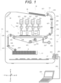
- FIG. 1 shows a schematic configuration of the ink jet printer 10.
- a cassette 12 which accommodates a sheet S which is an example of the recording medium, an upstream conveyance path 13 for the sheet S, a conveyance belt 14 which conveys the sheet S taken out of the cassette 12, a plurality of ink jet heads 100 to 103 which eject droplets of ink toward the sheet S on the conveyance belt 14, a downstream conveyance path 15 for the sheet S, a discharge tray 16, and a control board 17 are disposed inside a housing 11.
- An operation unit 18, which is a user interface, is disposed on an upper side of the housing 11.
- Image data to be printed on the sheet S is generated by, for example, a computer 200 which is an externally connected device.
- the image data generated by the computer 200 is sent to the control board 17 of the ink jet printer 10 through a cable 201 and connectors 202 and 203.
- a pickup roller 204 supplies the sheets S one by one from the cassette 12 to the upstream conveyance path 13.
- the upstream conveyance path 13 includes feed roller pairs 131 and 132 and sheet guide plates 133 and 134.
- the sheet S is fed to an upper surface of the conveyance belt 14 via the upstream conveyance path 13.
- An arrow 104 in the drawing indicates a conveyance path of the sheet S from the cassette 12 to the conveyance belt 14.
- the conveyance belt 14 is a mesh-shaped endless belt having a large number of through holes formed in a surface thereof.
- Three rollers including a drive roller 141 and driven rollers 142 and 143 rotatably support the conveyance belt 14.
- a motor 205 rotates the conveyance belt 14 by rotating the drive roller 141.
- the motor 205 is an example of a drive device.
- Reference numeral 105 in the drawing denotes a rotation direction of the conveyance belt 14.
- a negative pressure container 206 is disposed on a back surface side of the conveyance belt 14. The negative pressure container 206 is connected to a decompression fan 207.
- the fan 207 creates a negative pressure inside the negative pressure container 206 by forming an airflow, and causes the sheet S to be adsorbed and held on the upper surface of the conveyance belt 14.
- Reference numeral 106 in the drawing denotes a flow of the airflow.
- the ink jet heads 100 to 103 as an example of the liquid ejection head are disposed so as to face the sheet S adsorbed and held on the conveyance belt 14 with a slight gap of, for example, 1 mm therebetween.
- the ink jet heads 100 to 103 separately eject droplets of ink toward the sheet S.
- the ink jet heads 100 to 103 print an image when the sheet S passes below the ink jet heads 100 to 103.
- the ink jet heads 100 to 103 have the same structure except for different colors of the ink to be ejected.
- the colors of the ink are, for example, cyan, magenta, yellow, and black.
- the ink jet heads 100 to 103 are respectively connected to ink tanks 315 to 318 and ink supply pressure adjusting devices 321 to 324 via ink flow paths 311 to 314.
- the ink tanks 315 to 318 are disposed above the ink jet heads 100 to 103, respectively.
- each of the ink supply pressure adjusting devices 321 to 324 adjusts a pressure inside of each of the ink jet heads 100 to 103 to a negative pressure with respect to an atmospheric pressure, for example, -1.2 kPa, such that the ink does not leak from nozzles 24 (see FIG. 2 ) of the ink jet heads 100 to 103.
- the ink in each of the ink tanks 315 to 318 is supplied to each of the ink jet heads 100 to 103 by the ink supply pressure adjusting devices 321 to 324.
- the sheet S is fed from the conveyance belt 14 to the downstream conveyance path 15.
- the downstream conveyance path 15 includes feed roller pairs 151, 152, 153, and 154 and sheet guide plates 155 and 156 that define a conveyance path for the sheet S.
- the sheet S is fed from a discharge port 157 to the discharge tray 16 via the downstream conveyance path 15.
- An arrow 107 in the drawing indicates the conveyance path for the sheet S.
- the ink jet head 100 will be described with reference to FIGS. 2 to 5 , and the ink jet heads 101 to 103 also have the same structure as the ink jet head 100.
- the ink jet head 100 includes a head unit 2 as an example of a liquid ejection unit.
- the head unit 2 includes a nozzle plate 23 which is an example of a nozzle portion.
- the nozzles 24 of respective ejection channels that eject ink are disposed side by side along a first direction of the nozzle plate 23, for example, an X direction.
- a nozzle density is set within a range of, for example, 150 dpi to 1200 dpi.
- the nozzles 24 are not limited to being disposed side by side in one row, but may be disposed side by side in a plurality of rows.
- the head unit 2 is connected to the ink supply pressure adjusting device 321 in FIG. 1 via the ink flow path 311. A detailed internal configuration of the head unit 2 will be described later.
- the head unit 2 is connected to a flexible printed interconnect board 20.
- the flexible printed interconnect board 20 is a flexible printed interconnect board using, for example, a resin film.
- the flexible printed interconnect board 20 is, for example, a flexible printed circuit (FPC).
- the flexible printed interconnect board 20 is connected to a flexible printed circuit board 21.
- a drive integrated circuit (IC) 3 (hereinafter, referred to as a drive IC) which is a driver chip is mounted on the flexible printed circuit board 21.
- the flexible printed circuit board 21 is, for example, a chip on film (COF).
- the flexible printed circuit board 21 is connected to a printed board 22.
- the printed board 22 is a hard through-hole board in which an epoxy resin layer containing glass fibers and a copper interconnect layer are laminated in multiple layers.
- the drive IC 3 serving as a control unit of the ink jet head 100 temporarily stores data sent from the control board 17 including a CPU serving as a control unit of the ink jet printer 10 via the printed board 22, and applies a drive signal to each ejection channel so as to eject ink at a predetermined timing.
- the flexible printed interconnect board 20 such as an FPC is an example of a film substrate.
- the flexible printed interconnect board 20 and the flexible printed circuit board 21 on which the drive IC 3 is mounted are separate boards, and may be integrated with each other. A detailed configuration of the flexible printed interconnect board 20 will be described later.
- FIGS. 3 to 5 are partial cross-sectional views of the head unit 2.
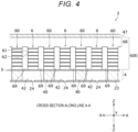
- FIG. 4 is a cross-sectional view taken along a line A-A in FIG. 3
- FIG. 5 is a cross-sectional view taken along a line B-B in FIG. 3 .
- the nozzle plate 23 is bonded to one surface of a pressure chamber board 4.
- the nozzle plate 23 is a rectangular plate formed of a resin such as a polyimide or a metal such as stainless steel.
- a diaphragm 5 is bonded to one surface of the pressure chamber board 4 on an opposite side from the nozzle plate 23.
- the diaphragm 5 has flexibility to be deformed when an external force is applied.
- the diaphragm 5 is a thin plate made of a metal such as nickel or stainless steel.
- the material of the diaphragm 5 may be other than a metal, such as a polyimide film.
- a pressure chamber 42 is formed in the pressure chamber board 4.
- the pressure chambers 42 of the respective ejection channels are disposed side by side at positions of the respective nozzles 24 and separately communicate with the nozzles 24.
- the pressure chamber board 4 is formed of a metal such as stainless steel.
- the pressure chamber 42 is formed by, for example, forming a rectangular opening penetrating a second direction, for example, a Z direction, in the pressure chamber board 4 and closing openings on both sides with the nozzle plate 23 and the diaphragm 5.
- the pressure chamber 42 communicates with a guide flow path 43 having a narrowed portion, and further communicates with an ink supply manifold 45 via an ink supply port 44 which is an opening hole penetrating the diaphragm 5.
- the guide flow path 43 is formed in a groove shape in a third direction, for example, a Y direction on one surface of the pressure chamber board 4 on a diaphragm 5 side for each pressure chamber 42.
- the ink supply manifold 45 is formed in a frame 46 bonded to one surface of the diaphragm 5.
- the ink supply manifold 45 extends in the X direction and communicates with the pressure chamber 42 of each channel via the ink supply port 44 and the guide flow path 43 of each channel.
- the ink supply manifold 45 serving as a common ink chamber communicates with the ink flow path 311 (see FIGS. 1 and 2 ).
- Actuators 6 of the respective ejection channels are disposed side by side at positions facing the pressure chambers 42 of the respective ejection channels with the diaphragm 5 sandwiched between the actuator 6 and the pressure chamber 42.
- An end surface of the actuator 6 of each ejection channel in a -Z direction is bonded to the diaphragm 5 constituting a part of a partition wall of the pressure chamber 42 by, for example, an adhesive.
- the actuator 6, which is an example of a piezoelectric actuator is a laminated piezoelectric actuator formed by alternately laminating a piezoelectric body 61 such as a piezoelectric element, a first internal electrode 62, and a second internal electrode 63 in a layered manner (particularly, see FIG. 3 ).
- the piezoelectric body 61 is disposed such that polarization directions are opposite to each other in, for example, the Z direction, and are deformed in a d33 mode.
- the piezoelectric body 61 is formed of a lead-containing piezoelectric material such as lead zirconate titanate (PZT) or a lead-free piezoelectric material such as potassium sodium niobate.
- the first internal electrode 62 and the second internal electrode 63 are conductive films formed on main surfaces of the piezoelectric body 61.
- the first internal electrode 62 and the second internal electrode 63 are formed of a conductive material that can be fired, such as silver palladium.
- the first internal electrodes 62 of the actuator 6 are formed up to one side surface of the actuator 6 in the Y direction, and are connected to an individual electrode 64 which is an external electrode formed on the corresponding side surface.
- the second internal electrodes 63 are formed up to the other side surface of the actuator 6 in a -Y direction, and are connected to a common electrode 65 which is an external electrode formed on the corresponding side surface.
- a dummy layer 68 is made of the same material as the piezoelectric body 61. However, the dummy layer 68 is not provided with an internal electrode and is not deformed since an electric field is not applied thereto.
- the individual electrode 64 and the common electrode 65 are formed of, for example, Ni, Cr, or Au.
- pillars 60 are disposed between the actuators 6 of the respective ejection channels via grooves 69.
- the pillar 60 is disposed at a position corresponding to a partition wall 40 between the adjacent pressure chambers 42.
- the drive actuators 6 and dummy actuators serving as the pillars 60 are collectively formed using the common piezoelectric body 61, the first internal electrodes 62, the second internal electrodes 63, the individual electrode 64, and the common electrode 65, and the grooves 69 are formed, thereby forming a laminated piezoelectric body block 600 having a comb tooth shape.
- the dummy layer 68 positioned on a base end side of the actuator 6 serves as a base that connects the actuators 6 and the pillars 60 that are alternately adjacent to each other.
- the laminated piezoelectric body block 600 is fixed by bonding end surfaces in the Z direction to a surface of a board 47.
- the individual electrode 64 of the actuators 6 of the laminated piezoelectric body block 600 is separated for each channel in the X direction which is a depth direction in FIG. 3 , and is connected to an individual interconnect 66 of the flexible printed interconnect board 20 (see FIG. 5 ).
- the flexible printed interconnect board 20 includes a resin film 26 as a base material, the individual interconnects 66, and a solder resist layer 27. The individual interconnect 66 will be described in detail later.
- the common electrode 65 of the actuators 6 connected to each other by using, for example, a portion of the dummy layer 68 is led out to an individual electrode 64 side by using, for example, side surfaces of the pillars 60 positioned at both ends of the laminated piezoelectric body block 600, or by extending the piezoelectric bodies 61 of the pillars 60 positioned at both ends of the laminated piezoelectric body block 600, and is connected to a common interconnect formed on the flexible printed interconnect board 21.
- FIG. 6 is a plan view of the flexible printed interconnect board 20.
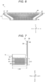
- FIG. 7 is a diagram in which the actuator 6 and the flexible printed interconnect board 20 are extracted from FIG. 3 .
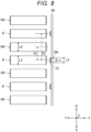
- FIG. 8 is a diagram in which the actuator 6 and the flexible printed interconnect board 20 are extracted from FIG. 5 .
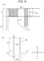
- FIG. 9 is a partially enlarged view of the flexible printed interconnect board 20.
- FIG. 10 is a plan view of the flexible printed interconnect board 20, the flexible printed circuit board 21, and the printed board 22 connected to one another.
- the individual interconnect 66 of the flexible printed interconnect board 20 is formed for each ejection channel from a solder connection region 7, which is a terminal portion on a side connected to the actuator 6, to a terminal portion 70 on a side connected to the flexible printed circuit board 21.
- the number of the individual interconnects 66 is illustrated to be small, but the number of the individual interconnects 66 is the same as the number of the actuators 6 to be driven.
- Each individual interconnect 66 is formed of a copper foil on a surface of the resin film 26 as the base material.
- a solder resist region 71 (see FIG. 6 ) of each individual interconnect 66 is covered with the solder resist layer 27 (see FIG.
- solder resist resin such as epoxy
- a cover layer made of a resin film may be attached to a copper foil surface of the flexible printed interconnect board 20, and the attached region may be used as the solder resist region.
- solder 72 solder plating
- cream solder may be attached to the solder connection region 7, and the surface of the individual interconnect 66 in the solder connection region 7 may be covered with the solder by heating.
- a common interconnect 67 is formed from the solder connection region 7 to the terminal portion 70 on the surface of the resin film 26, and the solder connection region 7 is covered with solder by solder plating or the like.
- the common interconnect 67 has an interconnect width larger than that of the individual interconnect 66 and is formed in a pair on both sides of the flexible printed interconnect board 20 in the X direction.
- the pair of common interconnects 67 are connected to both sides of the laminated piezoelectric body block 600, and are commonly connected to the common electrodes 65 of the actuators 6 connected to one another by using, for example, a portion of the dummy layer 68.
- the interconnect width of the individual interconnect 66 varies depending on a location as described later, and is formed within a range of 22 um to 84 ⁇ m, for example.
- the interconnect width of the common interconnect 67 is, for example, 0.8 mm.
- a thickness of the individual interconnect 66 and the common interconnect 67 is, for example, 8 ⁇ m.
- a lead portion 73 (see FIG. 9 ) of the individual interconnect 66 to overlap a surface of the individual electrode 64 of the actuator 6 has an interconnect width L1 smaller than a pillar width L2 of the actuator 6 in the X direction (see FIG. 8 ). Further, in the X direction, a width L3 after the solder plating is also preferably smaller than the pillar width L2 of the actuator 6.
- the individual interconnects 66 are disposed in parallel at equal intervals such as at a pitch P2 such that a center line of the lead portion 73 overlaps a center line of a pillar surface of the facing actuator 6.
- the individual interconnect 66 has the interconnect width changed in a tapered shape before and after a boundary portion 74 of the solder resist region 71.
- the interconnect width is larger on a solder resist region 71 side and smaller on a solder connection region 7 side in the X direction. That is, the individual interconnect 66 has a tapered portion 75 in which the interconnect width increases from the lead portion 73 toward the solder resist region 71.
- the actuator 6 and the pillar 60 are alternately disposed, and the individual interconnect 66 is not connected to the pillar 60, and thus, the interconnect width can be increased using an empty space.
- the interconnect width in the X direction can be three times or more as compared with that of the lead portion 73.
- the boundary portion 74 of the solder resist region 71 passes through the tapered portion 75.
- the boundary portion 74 of the solder resist region 71 is preferably positioned so as to straddle a center portion of the tapered portion 75 in the Z direction. More preferably, the boundary portion 74 is positioned at a half length of the tapered portion 75 in the Z direction.
- a portion of the lead portion 73 of the individual interconnect 66 closer to the -Z direction is connected to the individual electrode 64 of the actuator 6 (see FIG. 7 ).
- the change in the tapered shape is ended on the solder resist region 71 side with respect to the lead portion 73 soldered to the individual electrode 64 of the actuator 6.
- the interconnect width L1 of the lead portion 73 of the individual interconnect 66 is 22 um and the pitch P2 is 169 um which is the same as a pitch between the actuators 6.
- a width L5 of the solder connection region 7 in the Z direction is 1350 um from an edge of the flexible printed interconnect board 20, and a length L6 of the lead portion 73 of the individual interconnect 66 in the Z direction is 1075 um.
- the lead portion 73 is formed to have the same interconnect width without changing the interconnect width in the X direction.
- an interconnect width L7 in the X direction after changing to the tapered shape is 84 um.
- An interconnect interval L8 in the X direction between the adjacent individual interconnects 66 is 85 um.
- a length L9 of the tapered portion 75 in the Z direction is 550 um.
- a taper ratio in this case is about 1:9.
- the individual interconnect 66 in the solder connection region 7 is subjected to the solder plating to have a thickness of 10 ⁇ m.
- the flexible printed interconnect board 20 is positioned such that the center line of the lead portion 73 of the individual interconnect 66 overlaps the center line of the pillar surface of the facing actuator 6, the solder 72 is melted by heating, and the lead portions 73 of the individual interconnects 66 and the individual electrodes 64 of the actuators 6 are collectively solder-connected.
- the actuator 6 having a length L10 of 1700 um in the Y direction is solder-connected to overlap the pillar surface in the Z direction in a range where a length L11 of the lead portion 73 of the individual interconnect 66 is 660 um.
- the flexible printed interconnect board 20 generally has a thermal expansion coefficient different from that of the actuator 6.
- the flexible printed interconnect board 20 normally has a thermal expansion coefficient larger than that of the actuator 6, the flexible printed interconnect board 20 may be made smaller in size in advance in consideration of deformation due to heat during the solder connection, and the center line of the lead portion 73 of the individual interconnect 66 may be intended to exactly overlap and be bonded to the center line of the pillar surface of the facing actuator 6 by thermal expansion during the soldering.
- the interconnect width L1 (for example, 22 ⁇ m) of the lead portion 73 of the individual interconnect 66 in the X direction is smaller than the pillar width L2 (for example, 52.5 ⁇ m) of the actuator 6 in the X direction, and the width after the solder plating with a thickness of 10 um is also smaller than the pillar width of the actuator 6. Therefore, the excess solder 72 is prevented from wrapping around the side surface of the actuator 6 when being heated, and for example, the first internal electrode 62 and the second internal electrode 63 are prevented from being electrically connected. Further, the flowing solder 72 is prevented from attaching to the adjacent pillar 60. As described above, in a case where the pillar 60 is formed by the dummy actuator, when the solder 72 flows to the pillar 60 and is electrically connected to the individual interconnect 66, conduction may occur, which is however can be prevented.
- the solder used for soldering is supplied by plating or the like in advance the individual interconnect 66 of the solder connection region 7 which is an electrode at the tip end of the flexible printed interconnect board 20, but the solder may be supplied from the actuator 6 side by attaching the solder to the electrode 64 of the actuator 6. Both the electrode at the tip end of the flexible printed interconnect board 20 and the electrode 64 of the actuator 6 may be covered with the solder, so that the solder may be supplied from both the electrode at the tip end of the flexible printed interconnect board 20 and the electrode 64 of the actuator 6.
- ACF anisotropic conductive film
- ACP anisotropic conductive paste
- NCF non-conductive film
- NCP non-conductive paste
- the flexible printed circuit board 21 is a flexible film substrate formed using a synthetic resin film such as a polyimide.
- the drive IC 3 is, for example, a driver chip formed on a silicon semiconductor substrate.
- the individual interconnects 81, the common interconnects 82, input interconnects 83, a power supply interconnect 84 with a voltage V1, a power supply interconnect 85 with a voltage V2, and a ground interconnect 86 are formed.
- the individual interconnects 81 led out from the drive IC 3 are output interconnects of the drive waveform generated by the drive IC 3.
- the input interconnects 83 led out of the drive IC 3 are formed up to a terminal portion 87 on the side connected to the printed board 22. Since the drive IC 3 can be controlled by serial communication, the number of the input interconnects 83 can be smaller than the number of the individual interconnects 81 as the output interconnects.
- the power supply interconnect 84 with the voltage V1, the power supply interconnect 85 with the voltage V2, and the ground interconnect 86 are separately connected to the drive IC 3.
- the power supply interconnect 84 with the voltage V1, the power supply interconnect 85 with the voltage V2, and the ground interconnect 86 are separately formed up to the terminal portion 87 on the side connected to the printed board 22.
- the individual interconnects 81, the common interconnects 82, the input interconnects 83, the power supply interconnect 84 with the voltage V1, the power supply interconnect 85 with the voltage V2, and the ground interconnect 86 are formed of, for example, a copper foil.
- each interconnect of the flexible printed circuit board 21 is covered with a solder resist layer except for a mounting region of the drive IC 3 and the like, the terminal portions 8 and 87, and the like.
- Control lines 91, a power supply interconnect 92 with the voltage V1, a power supply interconnect 93 with the voltage V2, and a ground interconnect 94 are separately formed in a terminal portion 9 of the printed board 22.
- the control line 91 is connected to the input interconnects 83 of the flexible printed circuit board 21.
- the power supply interconnect 92 with the voltage V1 is connected to the power supply interconnect 84 of the flexible printed circuit board 21.
- the power supply interconnect 93 with the voltage V2 is connected to the power supply interconnect 85 of the flexible printed circuit board 21.
- the ground interconnect 94 is connected to the ground interconnect 86 and the common interconnects 82 of the flexible printed circuit board 21.
- a signal such as print data for selectively driving each actuator 6 sent from the control board 17 including the CPU which is the control unit of the ink jet printer 10 is given.
- the drive voltage V1 is applied to the power supply interconnect 92 by a power supply 95.
- the drive voltage V2 is applied to the power supply interconnect 93 by a power supply 96.
- the ground interconnect 94 is connected to a ground (GND) on the control board 17 of the ink jet printer 10, for example.
- FIG. 11 is a circuit diagram of the control system of the ink jet head 100.
- the actuators 6 (#1 ch, #2 ch, ⁇ #n ch) of the respective ejection channels connect the individual electrodes 64 to output terminals of drive drivers D (that is, drive circuits) of the drive IC 3 via the individual interconnects 66 and 81. Further, the actuators 6 connect the common electrodes 65 to a common potential via the common interconnects 67 and 82.
- the common potential is, for example, a ground (GND).
- the power supply 95 with the drive voltage V1 and the power supply 96 with the drive voltage V2 applied to the actuators 6 are connected to the drive IC 3.
- Each drive driver D of the drive IC 3 applies a drive waveform to the individual electrode 64 of each actuator 6 using the drive voltages V1 and V2 and the ground (GND).
- the voltage V1 is, for example, 20 V.
- the voltage V2 is, for example, 10 V.
- the ground (GND) is, for example, 0 V.
- the actuator 6 to be driven is based on, for example, print data.
- FIG. 12 is an example of the drive waveform applied to the actuator 6.
- the voltage V2 is applied to the individual electrode 64 to be in a standby state.
- an electric field is applied in a direction of a polarization axis of the piezoelectric body 61, and as shown in (a) in FIG. 13 , the actuator 6 extends in a lamination direction (Z direction) and a volume of the pressure chamber 42 is reduced.
- the above is performed prior to an ink ejection timing.
- a potential of the individual electrode 64 is first lowered to the ground (GND) at the ink ejection timing (time t1 in FIG.
- the actuator 6 extends in the lamination direction (Z direction) and the volume of the pressure chamber 42 is relatively reduced, whereby droplets R of ink are ejected from the nozzle 24.
- the voltage V1 is applied to the individual electrode 64 at a time t3 in FIG. 12 , and is returned to the voltage V2 at a time t4 after a predetermined time elapses.
- the volume of the pressure chamber 42 is reduced and restored by the expansion ((d) in FIG. 13 ) and restoration ((a) in FIG. 13 ) of the actuator 6 at this time, and a residual vibration due to this operation is attenuated.
- the volume of the pressure chamber 42 changes in accordance with a longitudinal vibration of the actuator 6 in the lamination direction, and the ink can be ejected.
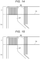
- the interconnect width of the individual interconnect 66 changes in the tapered shape before and after the boundary portion 74 of the solder resist region 71, and the interconnect width on the solder resist region 71 side larger. Accordingly, even if the interconnect width of the lead portion 73 connected to the individual electrode 64 of the actuator 6 is reduced, the interconnect width is increased so as to straddle the boundary portion 74 of the solder resist region 71, thereby preventing disconnection. Even if the interconnect width changes before and after the boundary portion 74 of the solder resist region 71, the disconnection is likely to occur when the interconnect width does not change in tapered shapes as in FIGS. 14 and 15 . For example, as shown in FIG.
- the actuator 6 is not limited to a laminated type in which a plurality of piezoelectric bodies 61 are laminated.
- the actuator 6 may be formed of a single layer of the piezoelectric body 61.
- the operation of the actuator when the drive voltage is applied is not limited to the longitudinal vibration.
- the embodiment is not limited to a drop-on-demand piezoelectric method, and may be applied to a continuous method.
- the ink jet head 100 of the ink jet printer 10 is described as an example of the liquid ejection head, but the liquid ejection head may be a shaping material ejection head of a 3D printer or a sample ejection head of a dispensing device.
- liquid ejection head of the above-described embodiment can be expressed as follows.
Landscapes
- Engineering & Computer Science (AREA)
- Manufacturing & Machinery (AREA)
- Particle Formation And Scattering Control In Inkjet Printers (AREA)
- Ink Jet (AREA)
Abstract
Description
- Embodiments described herein relate generally to a liquid ejection head.
- A liquid ejection head that supplies a predetermined amount of liquid to a predetermined position is known. The liquid ejection head is mounted on, for example, an ink jet printer, a 3D printer, or a dispensing device. The ink jet printer ejects droplets of ink from an ink jet head to form an image or the like on a surface of a recording medium. The 3D printer ejects droplets of a shaping material from a shaping material ejection head and cures the droplets to form a three-dimensional shaped object. The dispensing device ejects droplets of a sample and supplies a predetermined amount of the droplets to a plurality of containers or the like.
- The liquid ejection head includes a plurality of channels for ejecting liquid. Each channel includes a nozzle that ejects liquid, a pressure chamber that communicates with the nozzle, and a piezoelectric actuator that changes a volume of the pressure chamber. The liquid ejection head selects a channel for ejecting the liquid from the plurality of channels, and applies a drive waveform to the piezoelectric actuator of the selected channel to eject the liquid.
- The drive waveform is applied to a terminal of the piezoelectric actuator via a copper foil interconnect formed in a flexible interconnect board such as a flexible printed circuit (FPC). The interconnect of each channel disposed in a terminal portion of the flexible interconnect board is connected to the terminal of each piezoelectric actuator by collective soldering. However, for example, since an interconnect width is small for a reason of a fine pitch of the flexible interconnect board, disconnection is likely to occur. In particular, the disconnection is likely to occur at a boundary between a solder-connected region and a region in which a solder resist is applied in the flexible interconnect board.
- To this end, a liquid ejection head, a printer, and a 3-D printer according to appended claims are provided.
-
-
FIG. 1 is an overall configuration diagram of an ink jet printer including an ink jet head according to an embodiment; -
FIG. 2 is a perspective view; -
FIG. 3 is a partially enlarged cross-sectional view of a head unit; -
FIG. 4 is a partially enlarged cross-sectional view; -
FIG. 5 is a partially enlarged plan view; -
FIG. 6 is a plan view of a flexible printed interconnect board connected to the head unit; -
FIG. 7 is a diagram showing a connection structure between an actuator and the flexible printed interconnect board; -
FIG. 8 is a diagram showing the connection structure; -
FIG. 9 is a partially enlarged view of the flexible printed interconnect board; -
FIG. 10 is a plan view of the flexible printed interconnect board, a flexible printed circuit board, and a printed board connected to one another; -
FIG. 11 is a drive circuit of the ink jet head; -
FIG. 12 is a waveform diagram of a drive waveform generated by the drive circuit; -
FIG. 13 is a diagram showing operations of the actuator to which the drive waveform is applied; -
FIG. 14 is a partially enlarged view of a flexible printed interconnect board according to a comparative example; and -
FIG. 15 is a partially enlarged view. - In general, according to one embodiment, a liquid ejection head capable of preventing an occurrence of disconnection in a film substrate formed with an interconnect for applying a drive waveform to a piezoelectric actuator is provided.
- A liquid ejection head according to an embodiment includes a laminated piezoelectric body block and a film substrate. In the laminated piezoelectric body block, a plurality of piezoelectric actuators and pillars are alternately disposed. In the film substrate, a plurality of copper foil interconnects for applying drive waveforms to the respective piezoelectric actuators are formed, and the copper foil interconnects are soldered to terminals of the respective piezoelectric actuators to be electrically connected thereto. In the copper foil interconnects of the film substrate, an interconnect width changes to a tapered shape before and after a boundary portion of a solder resist region, the interconnect width on a solder resist region side is large, and the interconnect width on a solder connection region side is small.
- According to the present invention, the width of the copper foil interconnects changes to be a tapered shape around the boundary portion between the solder resist region and the solder connection region. The tapered shape is formed so that the width of each copper foil interconnect becomes smaller toward the solder connection region. In this case, a taper ratio is preferably from 1:10 to 1:8.
- Hereinafter, a liquid ejection head according to an embodiment will be described in detail with reference to the accompanying drawings. In the drawings, the same components are denoted by the same reference numerals.
- An
ink jet printer 10 that prints an image on a recording medium will be described as an example of an image forming apparatus on which the liquid ejection head according to the embodiment is mounted.FIG. 1 shows a schematic configuration of theink jet printer 10. In theink jet printer 10, acassette 12 which accommodates a sheet S which is an example of the recording medium, anupstream conveyance path 13 for the sheet S, aconveyance belt 14 which conveys the sheet S taken out of thecassette 12, a plurality ofink jet heads 100 to 103 which eject droplets of ink toward the sheet S on theconveyance belt 14, adownstream conveyance path 15 for the sheet S, adischarge tray 16, and acontrol board 17 are disposed inside ahousing 11. Anoperation unit 18, which is a user interface, is disposed on an upper side of thehousing 11. - Image data to be printed on the sheet S is generated by, for example, a
computer 200 which is an externally connected device. The image data generated by thecomputer 200 is sent to thecontrol board 17 of theink jet printer 10 through acable 201 andconnectors - A
pickup roller 204 supplies the sheets S one by one from thecassette 12 to theupstream conveyance path 13. Theupstream conveyance path 13 includesfeed roller pairs sheet guide plates conveyance belt 14 via theupstream conveyance path 13. Anarrow 104 in the drawing indicates a conveyance path of the sheet S from thecassette 12 to theconveyance belt 14. - The
conveyance belt 14 is a mesh-shaped endless belt having a large number of through holes formed in a surface thereof. Three rollers including adrive roller 141 and drivenrollers conveyance belt 14. Amotor 205 rotates theconveyance belt 14 by rotating thedrive roller 141. Themotor 205 is an example of a drive device.Reference numeral 105 in the drawing denotes a rotation direction of theconveyance belt 14. Anegative pressure container 206 is disposed on a back surface side of theconveyance belt 14. Thenegative pressure container 206 is connected to adecompression fan 207. Thefan 207 creates a negative pressure inside thenegative pressure container 206 by forming an airflow, and causes the sheet S to be adsorbed and held on the upper surface of theconveyance belt 14.Reference numeral 106 in the drawing denotes a flow of the airflow. - The
ink jet heads 100 to 103 as an example of the liquid ejection head are disposed so as to face the sheet S adsorbed and held on theconveyance belt 14 with a slight gap of, for example, 1 mm therebetween. Theink jet heads 100 to 103 separately eject droplets of ink toward the sheet S. The ink jet heads 100 to 103 print an image when the sheet S passes below the ink jet heads 100 to 103. The ink jet heads 100 to 103 have the same structure except for different colors of the ink to be ejected. The colors of the ink are, for example, cyan, magenta, yellow, and black. - The ink jet heads 100 to 103 are respectively connected to
ink tanks 315 to 318 and ink supplypressure adjusting devices 321 to 324 viaink flow paths 311 to 314. Theink tanks 315 to 318 are disposed above the ink jet heads 100 to 103, respectively. At the time of standby, each of the ink supplypressure adjusting devices 321 to 324 adjusts a pressure inside of each of the ink jet heads 100 to 103 to a negative pressure with respect to an atmospheric pressure, for example, -1.2 kPa, such that the ink does not leak from nozzles 24 (seeFIG. 2 ) of the ink jet heads 100 to 103. During the image formation, the ink in each of theink tanks 315 to 318 is supplied to each of the ink jet heads 100 to 103 by the ink supplypressure adjusting devices 321 to 324. - After the image formation, the sheet S is fed from the
conveyance belt 14 to thedownstream conveyance path 15. Thedownstream conveyance path 15 includes feed roller pairs 151, 152, 153, and 154 andsheet guide plates discharge port 157 to thedischarge tray 16 via thedownstream conveyance path 15. Anarrow 107 in the drawing indicates the conveyance path for the sheet S. - Next, a configuration of the ink jet heads 100 to 103 will be described. Hereinafter, the
ink jet head 100 will be described with reference toFIGS. 2 to 5 , and the ink jet heads 101 to 103 also have the same structure as theink jet head 100. - As shown in
FIG. 2 , theink jet head 100 includes ahead unit 2 as an example of a liquid ejection unit. Thehead unit 2 includes anozzle plate 23 which is an example of a nozzle portion. Thenozzles 24 of respective ejection channels that eject ink are disposed side by side along a first direction of thenozzle plate 23, for example, an X direction. A nozzle density is set within a range of, for example, 150 dpi to 1200 dpi. Thenozzles 24 are not limited to being disposed side by side in one row, but may be disposed side by side in a plurality of rows. Thehead unit 2 is connected to the ink supplypressure adjusting device 321 inFIG. 1 via theink flow path 311. A detailed internal configuration of thehead unit 2 will be described later. - The
head unit 2 is connected to a flexible printedinterconnect board 20. The flexible printedinterconnect board 20 is a flexible printed interconnect board using, for example, a resin film. The flexible printedinterconnect board 20 is, for example, a flexible printed circuit (FPC). The flexible printedinterconnect board 20 is connected to a flexible printedcircuit board 21. A drive integrated circuit (IC) 3 (hereinafter, referred to as a drive IC) which is a driver chip is mounted on the flexible printedcircuit board 21. The flexible printedcircuit board 21 is, for example, a chip on film (COF). The flexible printedcircuit board 21 is connected to a printedboard 22. The printedboard 22 is a hard through-hole board in which an epoxy resin layer containing glass fibers and a copper interconnect layer are laminated in multiple layers. Thedrive IC 3 serving as a control unit of theink jet head 100 temporarily stores data sent from thecontrol board 17 including a CPU serving as a control unit of theink jet printer 10 via the printedboard 22, and applies a drive signal to each ejection channel so as to eject ink at a predetermined timing. - The flexible printed
interconnect board 20 such as an FPC is an example of a film substrate. InFIG. 2 , the flexible printedinterconnect board 20 and the flexible printedcircuit board 21 on which thedrive IC 3 is mounted are separate boards, and may be integrated with each other. A detailed configuration of the flexible printedinterconnect board 20 will be described later. -
FIGS. 3 to 5 are partial cross-sectional views of thehead unit 2.FIG. 4 is a cross-sectional view taken along a line A-A inFIG. 3 , andFIG. 5 is a cross-sectional view taken along a line B-B inFIG. 3 . Thenozzle plate 23 is bonded to one surface of apressure chamber board 4. Thenozzle plate 23 is a rectangular plate formed of a resin such as a polyimide or a metal such as stainless steel. Adiaphragm 5 is bonded to one surface of thepressure chamber board 4 on an opposite side from thenozzle plate 23. Thediaphragm 5 has flexibility to be deformed when an external force is applied. Thediaphragm 5 is a thin plate made of a metal such as nickel or stainless steel. The material of thediaphragm 5 may be other than a metal, such as a polyimide film. - A
pressure chamber 42 is formed in thepressure chamber board 4. Thepressure chambers 42 of the respective ejection channels are disposed side by side at positions of therespective nozzles 24 and separately communicate with thenozzles 24. Thepressure chamber board 4 is formed of a metal such as stainless steel. Thepressure chamber 42 is formed by, for example, forming a rectangular opening penetrating a second direction, for example, a Z direction, in thepressure chamber board 4 and closing openings on both sides with thenozzle plate 23 and thediaphragm 5. - The
pressure chamber 42 communicates with aguide flow path 43 having a narrowed portion, and further communicates with anink supply manifold 45 via anink supply port 44 which is an opening hole penetrating thediaphragm 5. Theguide flow path 43 is formed in a groove shape in a third direction, for example, a Y direction on one surface of thepressure chamber board 4 on adiaphragm 5 side for eachpressure chamber 42. Theink supply manifold 45 is formed in aframe 46 bonded to one surface of thediaphragm 5. Theink supply manifold 45 extends in the X direction and communicates with thepressure chamber 42 of each channel via theink supply port 44 and theguide flow path 43 of each channel. Theink supply manifold 45 serving as a common ink chamber communicates with the ink flow path 311 (seeFIGS. 1 and2 ). - Actuators 6 of the respective ejection channels are disposed side by side at positions facing the
pressure chambers 42 of the respective ejection channels with thediaphragm 5 sandwiched between theactuator 6 and thepressure chamber 42. An end surface of theactuator 6 of each ejection channel in a -Z direction is bonded to thediaphragm 5 constituting a part of a partition wall of thepressure chamber 42 by, for example, an adhesive. Theactuator 6, which is an example of a piezoelectric actuator, is a laminated piezoelectric actuator formed by alternately laminating apiezoelectric body 61 such as a piezoelectric element, a firstinternal electrode 62, and a secondinternal electrode 63 in a layered manner (particularly, seeFIG. 3 ). Thepiezoelectric body 61 is disposed such that polarization directions are opposite to each other in, for example, the Z direction, and are deformed in a d33 mode. Thepiezoelectric body 61 is formed of a lead-containing piezoelectric material such as lead zirconate titanate (PZT) or a lead-free piezoelectric material such as potassium sodium niobate. - The first
internal electrode 62 and the secondinternal electrode 63 are conductive films formed on main surfaces of thepiezoelectric body 61. The firstinternal electrode 62 and the secondinternal electrode 63 are formed of a conductive material that can be fired, such as silver palladium. The firstinternal electrodes 62 of theactuator 6 are formed up to one side surface of theactuator 6 in the Y direction, and are connected to anindividual electrode 64 which is an external electrode formed on the corresponding side surface. The secondinternal electrodes 63 are formed up to the other side surface of theactuator 6 in a -Y direction, and are connected to acommon electrode 65 which is an external electrode formed on the corresponding side surface. Adummy layer 68 is made of the same material as thepiezoelectric body 61. However, thedummy layer 68 is not provided with an internal electrode and is not deformed since an electric field is not applied thereto. Theindividual electrode 64 and thecommon electrode 65 are formed of, for example, Ni, Cr, or Au. - In particular, as shown in
FIG. 4 ,pillars 60 are disposed between theactuators 6 of the respective ejection channels viagrooves 69. Thepillar 60 is disposed at a position corresponding to apartition wall 40 between theadjacent pressure chambers 42. Thedrive actuators 6 and dummy actuators serving as thepillars 60 are collectively formed using the commonpiezoelectric body 61, the firstinternal electrodes 62, the secondinternal electrodes 63, theindividual electrode 64, and thecommon electrode 65, and thegrooves 69 are formed, thereby forming a laminatedpiezoelectric body block 600 having a comb tooth shape. Thedummy layer 68 positioned on a base end side of theactuator 6 serves as a base that connects theactuators 6 and thepillars 60 that are alternately adjacent to each other. The laminatedpiezoelectric body block 600 is fixed by bonding end surfaces in the Z direction to a surface of aboard 47. - The
individual electrode 64 of theactuators 6 of the laminatedpiezoelectric body block 600 is separated for each channel in the X direction which is a depth direction inFIG. 3 , and is connected to anindividual interconnect 66 of the flexible printed interconnect board 20 (seeFIG. 5 ). The flexible printedinterconnect board 20 includes aresin film 26 as a base material, theindividual interconnects 66, and a solder resistlayer 27. Theindividual interconnect 66 will be described in detail later. Although not shown, thecommon electrode 65 of theactuators 6 connected to each other by using, for example, a portion of thedummy layer 68 is led out to anindividual electrode 64 side by using, for example, side surfaces of thepillars 60 positioned at both ends of the laminatedpiezoelectric body block 600, or by extending thepiezoelectric bodies 61 of thepillars 60 positioned at both ends of the laminatedpiezoelectric body block 600, and is connected to a common interconnect formed on the flexible printedinterconnect board 21. - Next, a connection structure between the
actuator 6 and the flexible printedinterconnect board 20 will be described in detail with reference toFIGS. 6 to 10 .FIG. 6 is a plan view of the flexible printedinterconnect board 20.FIG. 7 is a diagram in which theactuator 6 and the flexible printedinterconnect board 20 are extracted fromFIG. 3 .FIG. 8 is a diagram in which theactuator 6 and the flexible printedinterconnect board 20 are extracted fromFIG. 5 .FIG. 9 is a partially enlarged view of the flexible printedinterconnect board 20.FIG. 10 is a plan view of the flexible printedinterconnect board 20, the flexible printedcircuit board 21, and the printedboard 22 connected to one another. - As shown in
FIG. 6 , theindividual interconnect 66 of the flexible printedinterconnect board 20 is formed for each ejection channel from asolder connection region 7, which is a terminal portion on a side connected to theactuator 6, to aterminal portion 70 on a side connected to the flexible printedcircuit board 21. InFIG. 6 , for convenience of drawing, the number of theindividual interconnects 66 is illustrated to be small, but the number of theindividual interconnects 66 is the same as the number of theactuators 6 to be driven. Eachindividual interconnect 66 is formed of a copper foil on a surface of theresin film 26 as the base material. A solder resist region 71 (seeFIG. 6 ) of eachindividual interconnect 66 is covered with the solder resist layer 27 (seeFIG. 7 ) formed by applying a solder resist resin such as epoxy. Instead of applying the solder resist resin, a cover layer made of a resin film may be attached to a copper foil surface of the flexible printedinterconnect board 20, and the attached region may be used as the solder resist region. When a tip end of the flexible printedinterconnect board 20 on which the solder resistlayer 27 is formed is subjected to electrolytic plating with solder, a surface of eachindividual interconnect 66 in thesolder connection region 7 is plated with solder 72 (solder plating) (seeFIG. 8 ). Instead of the electrolytic plating, cream solder may be attached to thesolder connection region 7, and the surface of theindividual interconnect 66 in thesolder connection region 7 may be covered with the solder by heating. The solder is used for soldering described later. Similarly, acommon interconnect 67 is formed from thesolder connection region 7 to theterminal portion 70 on the surface of theresin film 26, and thesolder connection region 7 is covered with solder by solder plating or the like. In order to reduce current concentration when the plurality ofactuators 6 are simultaneously charged and discharged, thecommon interconnect 67 has an interconnect width larger than that of theindividual interconnect 66 and is formed in a pair on both sides of the flexible printedinterconnect board 20 in the X direction. The pair ofcommon interconnects 67 are connected to both sides of the laminatedpiezoelectric body block 600, and are commonly connected to thecommon electrodes 65 of theactuators 6 connected to one another by using, for example, a portion of thedummy layer 68. The interconnect width of theindividual interconnect 66 varies depending on a location as described later, and is formed within a range of 22 um to 84 µm, for example. The interconnect width of thecommon interconnect 67 is, for example, 0.8 mm. A thickness of theindividual interconnect 66 and thecommon interconnect 67 is, for example, 8 µm. - A lead portion 73 (see
FIG. 9 ) of theindividual interconnect 66 to overlap a surface of theindividual electrode 64 of theactuator 6 has an interconnect width L1 smaller than a pillar width L2 of theactuator 6 in the X direction (seeFIG. 8 ). Further, in the X direction, a width L3 after the solder plating is also preferably smaller than the pillar width L2 of theactuator 6. The individual interconnects 66 are disposed in parallel at equal intervals such as at a pitch P2 such that a center line of thelead portion 73 overlaps a center line of a pillar surface of the facingactuator 6. - The
individual interconnect 66 has the interconnect width changed in a tapered shape before and after aboundary portion 74 of the solder resistregion 71. The interconnect width is larger on a solder resistregion 71 side and smaller on asolder connection region 7 side in the X direction. That is, theindividual interconnect 66 has a tapered portion 75 in which the interconnect width increases from thelead portion 73 toward the solder resistregion 71. As described above, in the laminatedpiezoelectric body block 600, theactuator 6 and thepillar 60 are alternately disposed, and theindividual interconnect 66 is not connected to thepillar 60, and thus, the interconnect width can be increased using an empty space. As in an example of a size to be described later, the interconnect width in the X direction can be three times or more as compared with that of thelead portion 73. Theboundary portion 74 of the solder resistregion 71 passes through the tapered portion 75. Theboundary portion 74 of the solder resistregion 71 is preferably positioned so as to straddle a center portion of the tapered portion 75 in the Z direction. More preferably, theboundary portion 74 is positioned at a half length of the tapered portion 75 in the Z direction. A portion of thelead portion 73 of theindividual interconnect 66 closer to the -Z direction is connected to theindividual electrode 64 of the actuator 6 (seeFIG. 7 ). Accordingly, in the portion 75 in which the interconnect width of theindividual interconnect 66 changes in the tapered shape, the change in the tapered shape is ended on the solder resistregion 71 side with respect to thelead portion 73 soldered to theindividual electrode 64 of theactuator 6. - As an example of the size of each configuration, when the pillar width L2 of the
actuator 6 and a pillar width L4 of thepillar 60 are both 52.5 um and a pitch P1 between the alternately disposedactuator 6 andpillar 60 is 84.5 um in the X direction, the interconnect width L1 of thelead portion 73 of theindividual interconnect 66 is 22 um and the pitch P2 is 169 um which is the same as a pitch between theactuators 6. A width L5 of thesolder connection region 7 in the Z direction is 1350 um from an edge of the flexible printedinterconnect board 20, and a length L6 of thelead portion 73 of theindividual interconnect 66 in the Z direction is 1075 um. Thelead portion 73 is formed to have the same interconnect width without changing the interconnect width in the X direction. - In the tapered portion 75 following the
lead portion 73 in the Z direction, an interconnect width L7 in the X direction after changing to the tapered shape is 84 um. An interconnect interval L8 in the X direction between the adjacentindividual interconnects 66 is 85 um. A length L9 of the tapered portion 75 in the Z direction is 550 um. A taper ratio in this case is about 1:9. Theboundary portion 74 of the solder resistregion 71 passes through the half length (= 275 um) of the tapered portion 75 in the Z direction. Theindividual interconnect 66 in thesolder connection region 7 is subjected to the solder plating to have a thickness of 10 µm. - The flexible printed
interconnect board 20 is positioned such that the center line of thelead portion 73 of theindividual interconnect 66 overlaps the center line of the pillar surface of the facingactuator 6, thesolder 72 is melted by heating, and thelead portions 73 of theindividual interconnects 66 and theindividual electrodes 64 of theactuators 6 are collectively solder-connected. For example, as shown inFIG. 7 , theactuator 6 having a length L10 of 1700 um in the Y direction is solder-connected to overlap the pillar surface in the Z direction in a range where a length L11 of thelead portion 73 of theindividual interconnect 66 is 660 um. The flexible printedinterconnect board 20 generally has a thermal expansion coefficient different from that of theactuator 6. Since the flexible printedinterconnect board 20 normally has a thermal expansion coefficient larger than that of theactuator 6, the flexible printedinterconnect board 20 may be made smaller in size in advance in consideration of deformation due to heat during the solder connection, and the center line of thelead portion 73 of theindividual interconnect 66 may be intended to exactly overlap and be bonded to the center line of the pillar surface of the facingactuator 6 by thermal expansion during the soldering. - The interconnect width L1 (for example, 22 µm) of the
lead portion 73 of theindividual interconnect 66 in the X direction is smaller than the pillar width L2 (for example, 52.5 µm) of theactuator 6 in the X direction, and the width after the solder plating with a thickness of 10 um is also smaller than the pillar width of theactuator 6. Therefore, theexcess solder 72 is prevented from wrapping around the side surface of theactuator 6 when being heated, and for example, the firstinternal electrode 62 and the secondinternal electrode 63 are prevented from being electrically connected. Further, the flowingsolder 72 is prevented from attaching to theadjacent pillar 60. As described above, in a case where thepillar 60 is formed by the dummy actuator, when thesolder 72 flows to thepillar 60 and is electrically connected to theindividual interconnect 66, conduction may occur, which is however can be prevented. - In the present embodiment, the solder used for soldering is supplied by plating or the like in advance the
individual interconnect 66 of thesolder connection region 7 which is an electrode at the tip end of the flexible printedinterconnect board 20, but the solder may be supplied from theactuator 6 side by attaching the solder to theelectrode 64 of theactuator 6. Both the electrode at the tip end of the flexible printedinterconnect board 20 and theelectrode 64 of theactuator 6 may be covered with the solder, so that the solder may be supplied from both the electrode at the tip end of the flexible printedinterconnect board 20 and theelectrode 64 of theactuator 6. - As shown in
FIG. 10 , theindividual interconnects 66 and thecommon interconnects 67 led out to theterminal portions 70 overlap aterminal portion 8 of the flexible printedcircuit board 21 and are connected toindividual interconnects 81 andcommon interconnects 82 of the flexible printedcircuit board 21, respectively. Since the pitch of theindividual interconnects 66 on aterminal portion 70 side is smaller than that on thesolder connection region 7 side in the X direction, theindividual interconnects 66 are fixed by an anisotropic conductive film (ACF), an anisotropic conductive paste (ACP), a non-conductive film (NCF), a non-conductive paste (NCP), or the like instead of the solder connection, and are anisotropically connected in a thickness direction. - The flexible printed
circuit board 21 is a flexible film substrate formed using a synthetic resin film such as a polyimide. Thedrive IC 3 is, for example, a driver chip formed on a silicon semiconductor substrate. On the flexible printedcircuit board 21, theindividual interconnects 81, thecommon interconnects 82, input interconnects 83, apower supply interconnect 84 with a voltage V1, apower supply interconnect 85 with a voltage V2, and aground interconnect 86 are formed. The individual interconnects 81 led out from thedrive IC 3 are output interconnects of the drive waveform generated by thedrive IC 3. On the other hand, the input interconnects 83 led out of thedrive IC 3 are formed up to a terminal portion 87 on the side connected to the printedboard 22. Since thedrive IC 3 can be controlled by serial communication, the number of the input interconnects 83 can be smaller than the number of theindividual interconnects 81 as the output interconnects. - The
power supply interconnect 84 with the voltage V1, thepower supply interconnect 85 with the voltage V2, and theground interconnect 86 are separately connected to thedrive IC 3. Thepower supply interconnect 84 with the voltage V1, thepower supply interconnect 85 with the voltage V2, and theground interconnect 86 are separately formed up to the terminal portion 87 on the side connected to the printedboard 22. The individual interconnects 81, thecommon interconnects 82, the input interconnects 83, thepower supply interconnect 84 with the voltage V1, thepower supply interconnect 85 with the voltage V2, and theground interconnect 86 are formed of, for example, a copper foil. Although not shown, each interconnect of the flexible printedcircuit board 21 is covered with a solder resist layer except for a mounting region of thedrive IC 3 and the like, theterminal portions 8 and 87, and the like. -
Control lines 91, apower supply interconnect 92 with the voltage V1, apower supply interconnect 93 with the voltage V2, and aground interconnect 94 are separately formed in a terminal portion 9 of the printedboard 22. Thecontrol line 91 is connected to the input interconnects 83 of the flexible printedcircuit board 21. Thepower supply interconnect 92 with the voltage V1 is connected to thepower supply interconnect 84 of the flexible printedcircuit board 21. Thepower supply interconnect 93 with the voltage V2 is connected to thepower supply interconnect 85 of the flexible printedcircuit board 21. Theground interconnect 94 is connected to theground interconnect 86 and thecommon interconnects 82 of the flexible printedcircuit board 21. To thecontrol line 91, a signal such as print data, for selectively driving eachactuator 6 sent from thecontrol board 17 including the CPU which is the control unit of theink jet printer 10 is given. The drive voltage V1 is applied to thepower supply interconnect 92 by apower supply 95. The drive voltage V2 is applied to thepower supply interconnect 93 by apower supply 96. Theground interconnect 94 is connected to a ground (GND) on thecontrol board 17 of theink jet printer 10, for example. - Next, a control system of the
ink jet head 100 will be described.FIG. 11 is a circuit diagram of the control system of theink jet head 100. As shown inFIG. 11 , the actuators 6 (#1 ch, #2 ch,··· #n ch) of the respective ejection channels connect theindividual electrodes 64 to output terminals of drive drivers D (that is, drive circuits) of thedrive IC 3 via the individual interconnects 66 and 81. Further, theactuators 6 connect thecommon electrodes 65 to a common potential via thecommon interconnects power supply 95 with the drive voltage V1 and thepower supply 96 with the drive voltage V2 applied to theactuators 6 are connected to thedrive IC 3. - Next, an ink ejection operation will be described with reference to
FIGS. 12 and13 . Each drive driver D of thedrive IC 3 applies a drive waveform to theindividual electrode 64 of eachactuator 6 using the drive voltages V1 and V2 and the ground (GND). The voltage V1 is, for example, 20 V. The voltage V2 is, for example, 10 V. The ground (GND) is, for example, 0 V. Theactuator 6 to be driven is based on, for example, print data. -
FIG. 12 is an example of the drive waveform applied to theactuator 6. As shown inFIG. 12 , when theactuator 6 in which a ground potential is applied to thecommon electrode 65 is driven, the voltage V2 is applied to theindividual electrode 64 to be in a standby state. When the voltage V2 is applied, an electric field is applied in a direction of a polarization axis of thepiezoelectric body 61, and as shown in (a) inFIG. 13 , theactuator 6 extends in a lamination direction (Z direction) and a volume of thepressure chamber 42 is reduced. The above is performed prior to an ink ejection timing. Thereafter, a potential of theindividual electrode 64 is first lowered to the ground (GND) at the ink ejection timing (time t1 inFIG. 12 ), whereby theextended actuator 6 returns to an original state, that is, relatively contracts, and the volume of thepressure chamber 42 relatively expands, as shown in (b) inFIG. 13 . As the volume of thepressure chamber 42 expands, the ink flows into thepressure chamber 42 via theguide flow path 43. - Then, for example, when the voltage V2 is applied to the
individual electrode 64 at a time t2 inFIG. 12 after 1/2 of a pressure vibration cycle of thehead unit 2 elapses, as shown in (c) inFIG. 13 , theactuator 6 extends in the lamination direction (Z direction) and the volume of thepressure chamber 42 is relatively reduced, whereby droplets R of ink are ejected from thenozzle 24. Then, for example, after 1/2 of the pressure vibration cycle of thehead unit 2 elapses, the voltage V1 is applied to theindividual electrode 64 at a time t3 inFIG. 12 , and is returned to the voltage V2 at a time t4 after a predetermined time elapses. The volume of thepressure chamber 42 is reduced and restored by the expansion ((d) inFIG. 13 ) and restoration ((a) inFIG. 13 ) of theactuator 6 at this time, and a residual vibration due to this operation is attenuated. Thus, the volume of thepressure chamber 42 changes in accordance with a longitudinal vibration of theactuator 6 in the lamination direction, and the ink can be ejected. - As described above, in the flexible printed
interconnect board 20, the interconnect width of theindividual interconnect 66 changes in the tapered shape before and after theboundary portion 74 of the solder resistregion 71, and the interconnect width on the solder resistregion 71 side larger. Accordingly, even if the interconnect width of thelead portion 73 connected to theindividual electrode 64 of theactuator 6 is reduced, the interconnect width is increased so as to straddle theboundary portion 74 of the solder resistregion 71, thereby preventing disconnection. Even if the interconnect width changes before and after theboundary portion 74 of the solder resistregion 71, the disconnection is likely to occur when the interconnect width does not change in tapered shapes as inFIGS. 14 and 15 . For example, as shown inFIG. 14 , when a non-tapered interconnect width conversion unit is located at a boundary between the solder resistregion 71 and thesolder connection region 7 or in the solder resistregion 71, the thinner interconnect is likely to be disconnected when the flexible printedinterconnect board 20 is curved. In addition, as shown inFIG. 15 , when a non-tapered interconnect width conversion unit is located on a side of a region where the solder plating is performed, the solder which is plated on a thicker interconnect is likely to cause a short circuit. - As described above, according to the above-described embodiment, it is possible to prevent an occurrence of the disconnection in the flexible printed
interconnect board 20 in which theindividual interconnects 66 for applying the drive waveform to theactuator 6 are formed of the copper foil. - The
actuator 6 is not limited to a laminated type in which a plurality ofpiezoelectric bodies 61 are laminated. Theactuator 6 may be formed of a single layer of thepiezoelectric body 61. The operation of the actuator when the drive voltage is applied is not limited to the longitudinal vibration. Further, the embodiment is not limited to a drop-on-demand piezoelectric method, and may be applied to a continuous method. - In the above-described embodiment, the
ink jet head 100 of theink jet printer 10 is described as an example of the liquid ejection head, but the liquid ejection head may be a shaping material ejection head of a 3D printer or a sample ejection head of a dispensing device. - That is, the liquid ejection head of the above-described embodiment can be expressed as follows.
- (1) A liquid ejection head including:
- a laminated piezoelectric body block in which a plurality of piezoelectric actuators and pillars are alternately disposed; and
- a film substrate in which a plurality of copper foil interconnects for applying drive waveforms to the respective piezoelectric actuators are formed, and the copper foil interconnects are soldered to terminals of the respective piezoelectric actuators to be electrically connected thereto, in which
- in the copper foil interconnects of the film substrate, an interconnect width changes to a tapered shape before and after a boundary portion of a solder resist region, the interconnect width on a solder resist region side is large, and the interconnect width on a solder connection region side is small.
- (2) In the copper foil interconnects, an interconnect width of a lead portion soldered to the terminal of the piezoelectric actuator is smaller than a pillar width of the piezoelectric actuator and changes to the tapered shape to be equal to or larger than the pillar width of the piezoelectric actuator, and
the boundary portion of the solder resist region straddles a center portion of a portion where the interconnect width changes to the tapered shape. - (3) The solder resist region is formed by covering a surface of a copper foil of the film substrate with a resin film.
- (4) The solder resist region is formed of a resin applied to a surface of a copper foil of the film substrate.
- (5) The soldered portion of the copper foil interconnect is outside the solder resist region and is subjected to solder plating.
- (6) In a portion in which the interconnect width changes to the tapered shape, the interconnect width is increased by utilizing a fact that the pillar is provided between the adjacent piezoelectric actuators.
- (7) In the portion in which the interconnect width changes to the tapered shape, the change is ended on the solder resist region side with respect to the lead portion soldered to the terminal of the piezoelectric actuator.
- The embodiments have been presented by way of example and are not intended to limit the scope of the disclosure. These novel embodiments can be implemented in various other forms, and various omissions, substitutions, and modifications can be made without departing from the gist of the disclosure. The embodiments and the modifications thereof are included in the scope and the gist of the disclosure, and are included in a scope of the disclosure disclosed in the claims and equivalents thereof.
Claims (12)
- A liquid ejection head (100-103) comprising:a laminated piezoelectric body block (600) in which a plurality of piezoelectric actuators (6) and pillars (60) are alternately disposed; anda film substrate in which a plurality of copper foil interconnects for applying drive waveforms to the respective piezoelectric actuators are formed, and the copper foil interconnects are soldered to terminals of the respective piezoelectric actuators to be electrically connected thereto, whereinin the copper foil interconnects of the film substrate, an interconnect width changes to a tapered shape before and after a boundary portion (74) of a solder resist region (71), the interconnect width on a solder resist region side is large, and the interconnect width on a solder connection (7) region side is small.
- The head according to claim 1, whereinin the copper foil interconnects, an interconnect width of a lead portion soldered to the terminal of the piezoelectric actuator is smaller than a pillar width of the piezoelectric actuator and changes to the tapered shape to be equal to or larger than the pillar width of the piezoelectric actuator, andthe boundary portion of the solder resist region straddles a center portion of a portion where the interconnect width changes to the tapered shape.
- The head according to claim 1 or 2, wherein
the solder resist region is formed by covering a surface of a copper foil of the film substrate with a resin film. - The head according to claim 1 or 2, wherein
the solder resist region is formed of a resin applied to a surface of a copper foil of the film substrate. - The head according to any one of claims 1 to 4, wherein
the soldered portion of the copper foil interconnect is outside the solder resist region and is subjected to solder plating. - The head according to any one of claims 1 to 5, wherein a taper ratio of the interconnect width having a tapered shape before and after the boundary portion (74) of a solder resist region (71)is from 1:10 to 1:8.
- The head according to any one of claims 1 to 6, wherein the actuator (6) is formed by alternatively laminating a piezoelectric body (61) a first internal electrode (62) and a second internal electrode (63) in a layered manner.
- The head according to any one of claims 1 to 7, wherein the liquid ejection head includes a plurality of channels, each channel including a nozzle that ejects liquid, a pressure chamber that communicates with the nozzle, and the piezoelectric actuator that changes a volume of the pressure chamber.
- The head according to claim 8, wherein the liquid ejection head is configured to select a channel for ejecting the liquid from the plurality of channels, and applies a drive waveform to the piezoelectric actuator of the selected channel.
- The head according to any one of claims 8 or 9, wherein the copper foil interconnects are individual interconnects for each ejection channel.
- An ink jet printer comprising a head according to any one of claims 1 to 10.
- A 3D printer comprising a head according to any one of claims 1 to 10.
Applications Claiming Priority (1)
| Application Number | Priority Date | Filing Date | Title |
|---|---|---|---|
| JP2023211452A JP2025095449A (en) | 2023-12-14 | 2023-12-14 | Liquid ejection head |
Publications (2)
| Publication Number | Publication Date |
|---|---|
| EP4570504A1 true EP4570504A1 (en) | 2025-06-18 |
| EP4570504B1 EP4570504B1 (en) | 2026-08-12 |
Family
ID=92843317
Family Applications (1)
| Application Number | Title | Priority Date | Filing Date |
|---|---|---|---|
| EP24201170.8A Active EP4570504B1 (en) | 2023-12-14 | 2024-09-18 | Liquid ejection head |
Country Status (3)
| Country | Link |
|---|---|
| EP (1) | EP4570504B1 (en) |
| JP (1) | JP2025095449A (en) |
| CN (1) | CN120156188A (en) |
Citations (4)
| Publication number | Priority date | Publication date | Assignee | Title |
|---|---|---|---|---|
| US20070279459A1 (en) * | 2006-06-01 | 2007-12-06 | Seiko Epson Corporation | Piezoelectric element unit, manufacturing method of the same, and liquid ejecting head using the same |
| US20110298872A1 (en) * | 2010-06-08 | 2011-12-08 | Ricoh Company, Ltd. | Piezoelectric actuator, liquid ejection head, and image forming apparatus |
| US20120182356A1 (en) * | 2011-01-14 | 2012-07-19 | Ricoh Company, Ltd. | Liquid discharge head, method of manufacturing liquid discharge head, and image forming device |
| JP2023132399A (en) * | 2022-03-11 | 2023-09-22 | 東芝テック株式会社 | liquid discharge head |
-
2023
- 2023-12-14 JP JP2023211452A patent/JP2025095449A/en active Pending
-
2024
- 2024-08-27 CN CN202411185282.7A patent/CN120156188A/en active Pending
- 2024-09-18 EP EP24201170.8A patent/EP4570504B1/en active Active
Patent Citations (4)
| Publication number | Priority date | Publication date | Assignee | Title |
|---|---|---|---|---|
| US20070279459A1 (en) * | 2006-06-01 | 2007-12-06 | Seiko Epson Corporation | Piezoelectric element unit, manufacturing method of the same, and liquid ejecting head using the same |
| US20110298872A1 (en) * | 2010-06-08 | 2011-12-08 | Ricoh Company, Ltd. | Piezoelectric actuator, liquid ejection head, and image forming apparatus |
| US20120182356A1 (en) * | 2011-01-14 | 2012-07-19 | Ricoh Company, Ltd. | Liquid discharge head, method of manufacturing liquid discharge head, and image forming device |
| JP2023132399A (en) * | 2022-03-11 | 2023-09-22 | 東芝テック株式会社 | liquid discharge head |
Also Published As
| Publication number | Publication date |
|---|---|
| JP2025095449A (en) | 2025-06-26 |
| EP4570504B1 (en) | 2026-08-12 |
| CN120156188A (en) | 2025-06-17 |
Similar Documents
| Publication | Publication Date | Title |
|---|---|---|
| JP2012091510A (en) | Liquid ejection head and recorder using the same | |
| EP2769846B1 (en) | Liquid ejection apparatus and connection method for flexible wiring board | |
| JP5451009B2 (en) | Liquid discharge head and printing apparatus using the same | |
| US9156259B2 (en) | Liquid ejecting head and liquid ejecting apparatus | |
| CN115122772A (en) | liquid nozzle | |
| JP2016221703A (en) | LIQUID DISCHARGE DEVICE, LIQUID DISCHARGE DEVICE MANUFACTURING METHOD, WIRING MEMBER, AND WIRING MEMBER MANUFACTURING METHOD | |
| EP3175988B1 (en) | Inkjet head and printer | |
| CN115891430B (en) | Driving device and liquid spray head | |
| EP4303012A1 (en) | Liquid ejection head | |
| JP4923826B2 (en) | Droplet discharge head and droplet discharge apparatus | |
| JP2025095449A (en) | Liquid ejection head | |
| JP2021178479A (en) | Circuit board and liquid discharge head | |
| US20260091584A1 (en) | Liquid ejection head | |
| JP2023132399A (en) | liquid discharge head | |
| US20260091585A1 (en) | Liquid ejection head, liquid ejection device, and image forming apparatus | |
| US20260091587A1 (en) | Liquid ejection head, liquid ejection device, and image forming apparatus | |
| JP7636225B2 (en) | Film wiring board for driving liquid ejection head, liquid ejection head | |
| JP2025052839A (en) | Liquid ejection head | |
| JP7461760B2 (en) | Liquid ejection device and method for manufacturing the same | |
| JP2024106211A (en) | Liquid ejection head | |
| CN119682393A (en) | Liquid ejection head | |
| JP2023154467A (en) | liquid discharge head | |
| JP2024047748A (en) | Liquid ejection head | |
| JP2024047749A (en) | Liquid ejection head | |
| CN119682392A (en) | Liquid spray head |
Legal Events
| Date | Code | Title | Description |
|---|---|---|---|
| PUAI | Public reference made under article 153(3) epc to a published international application that has entered the european phase |
Free format text: ORIGINAL CODE: 0009012 |
|
| STAA | Information on the status of an ep patent application or granted ep patent |
Free format text: STATUS: THE APPLICATION HAS BEEN PUBLISHED |
|
| AK | Designated contracting states |
Kind code of ref document: A1 Designated state(s): AL AT BE BG CH CY CZ DE DK EE ES FI FR GB GR HR HU IE IS IT LI LT LU LV MC ME MK MT NL NO PL PT RO RS SE SI SK SM TR |
|
| STAA | Information on the status of an ep patent application or granted ep patent |
Free format text: STATUS: REQUEST FOR EXAMINATION WAS MADE |
|
| 17P | Request for examination filed |
Effective date: 20251204 |
|
| GRAP | Despatch of communication of intention to grant a patent |
Free format text: ORIGINAL CODE: EPIDOSNIGR1 |
|
| STAA | Information on the status of an ep patent application or granted ep patent |
Free format text: STATUS: GRANT OF PATENT IS INTENDED |
|
| INTG | Intention to grant announced |
Effective date: 20260326 |
|
| GRAS | Grant fee paid |
Free format text: ORIGINAL CODE: EPIDOSNIGR3 |
|
| GRAA | (expected) grant |
Free format text: ORIGINAL CODE: 0009210 |
|
| STAA | Information on the status of an ep patent application or granted ep patent |
Free format text: STATUS: THE PATENT HAS BEEN GRANTED |
|
| P01 | Opt-out of the competence of the unified patent court (upc) registered |
Free format text: CASE NUMBER: UPC_APP_0018047_4570504/2026 Effective date: 20260610 |
|
| AK | Designated contracting states |
Kind code of ref document: B1 Designated state(s): AL AT BE BG CH CY CZ DE DK EE ES FI FR GB GR HR HU IE IS IT LI LT LU LV MC ME MK MT NL NO PL PT RO RS SE SI SK SM TR |
|
| REG | Reference to a national code |
Ref country code: CH Ref legal event code: F10 Free format text: ST27 STATUS EVENT CODE: U-0-0-F10-F00 (AS PROVIDED BY THE NATIONAL OFFICE) Effective date: 20260812 Ref country code: GB Ref legal event code: FG4D |