EP4570463A2 - Cutting apparatus and method - Google Patents
Cutting apparatus and method Download PDFInfo
- Publication number
- EP4570463A2 EP4570463A2 EP25162393.0A EP25162393A EP4570463A2 EP 4570463 A2 EP4570463 A2 EP 4570463A2 EP 25162393 A EP25162393 A EP 25162393A EP 4570463 A2 EP4570463 A2 EP 4570463A2
- Authority
- EP
- European Patent Office
- Prior art keywords
- capsule
- contact surface
- abutting element
- spindle
- plastics
- Prior art date
- Legal status (The legal status is an assumption and is not a legal conclusion. Google has not performed a legal analysis and makes no representation as to the accuracy of the status listed.)
- Pending
Links
Images

Classifications
-
- B—PERFORMING OPERATIONS; TRANSPORTING
- B26—HAND CUTTING TOOLS; CUTTING; SEVERING
- B26F—PERFORATING; PUNCHING; CUTTING-OUT; STAMPING-OUT; SEVERING BY MEANS OTHER THAN CUTTING
- B26F1/00—Perforating; Punching; Cutting-out; Stamping-out; Apparatus therefor
- B26F1/18—Perforating by slitting, i.e. forming cuts closed at their ends without removal of material
-
- B—PERFORMING OPERATIONS; TRANSPORTING
- B26—HAND CUTTING TOOLS; CUTTING; SEVERING
- B26F—PERFORATING; PUNCHING; CUTTING-OUT; STAMPING-OUT; SEVERING BY MEANS OTHER THAN CUTTING
- B26F2210/00—Perforating, punching, cutting-out, stamping-out, severing by means other than cutting of specific products
- B26F2210/04—Making plastic pilferproof screw caps by cutting a tamper ring
Definitions
- the invention relates to a cutting apparatus and method, in particular for cutting or incising products made of plastics and/or a metal material (for example aluminium and/or steel).
- the invention can be used to produce capsules made of plastics for closing containers, in particular for making the preferential weakening or fracture line, arranged between the closing portion of the capsule and the guarantee ring or band, for defining a safety device that is able to proof that the first opening of the capsule has taken place.
- a cutting apparatus comprising a rotating carousel that carries a plurality of spindles, each of which spindle is rotatable around its own axis, in which a spindle engages a respective capsule to be cut and, by a movement that comprises a rotation around the axis thereof and a rotation around the axis of the carousel, rotates the capsule on an abutting element that carries a shaped blade according to the type of cut that it is desired to perform.
- Patent publications WO 2004/004993 A1 and WO 2011/058500 A1 show examples of cutting apparatuses of the type mentioned above.
- the latter in order to rotate the capsules with respect to the cutting tool, the latter is generally fitted to a circular sector provided with knurling that is couplable by meshing with complementary knurling provided on the side wall of the capsule.
- the knurled sector In the first place, with the varying of the dimensions of the capsule and/or of the shape and/or of the pitch of the knurling, the knurled sector has to be replaced, with a resulting increase in the complication and cost of the machining.
- One object of the invention is to provide a cutting apparatus and/or method that is able to remedy one or more of the aforesaid drawbacks of the prior art.
- One advantage is to enable cutting machining with varying of the dimensions of the capsule and/or of the shape and/or of the pitch of the knurling on the capsule, without the need to replace components of the cutting apparatus.
- One advantage is to ensure a correct cut also in the case of closing capsules provided with knurls with teeth spaced far apart from one another and/or in the case of closing capsules devoid of lateral knurling.
- One advantage is to make a cutting apparatus and method of great versatility, which are applicable to capsules of various dimensions and types.
- One advantage is to make available a cutting apparatus that is constructionally simple and cheap to make.
- One advantage is to provide a cutting apparatus with relatively high mechanical resistance, in particular to wear and fracture.
- the cutting apparatus comprises an abutting element, in particular in the shape of a circular sector, comprising a contact surface which is intended for contact with the capsules and which is made of plastics with a friction coefficient suitable for ensuring rolling of the capsules by friction, for example a dynamic friction coefficient comprised between 0.15 and 0.30.
- the plastics of the contact surface on which rolling by friction occurs may comprise ultra-high molecular weight polyethylene UHMWPE.
- a cutting apparatus suitable for forming a preferential fracture line in a capsule for closing containers, comprises at least one rotating spindle that can be engaged with a respective capsule that is rolled against a contact surface of an abutting element made of a material that comprises ultra-high molecular weight polyethylene, a fixed blade being arranged for performing cutting on the rolling capsule.
- the contact surface could be arranged on the spindle, in addition to or instead of the contact surface on the abutting element.
- a cutting method comprises the step of rolling a capsule for closing containers against a contact surface made of plastics, in particular of ultra-high molecular weight polyethylene, whilst a fixed blade forms a preferential fracture line on the rolling capsule.
- a cutting apparatus has been indicated overall that is usable in a plant for producing capsules (in particular made of plastics) for closing containers, in particular for making the preferential weakening or fracture line, arranged between the closing portion of a capsule and the guarantee ring or band, to give rise to a security device that is able to bear witness to the first opening of the capsule.
- the cutting apparatus 1 may comprise, in particular, at least one abutting element 2 comprising at least one abutting surface configured in such a manner that a capsule C for closing containers can roll against the abutting surface along a rolling path.
- the abutting surface and the corresponding rolling path may have, as in this specific embodiment, a longitudinal extent substantially in the shape of a circular sector.
- the cutting apparatus 1 may comprise, in particular, at least one blade 3 arranged on the abutting element 2 to perform a cut on a capsule C that rolls against the abutting surface to form a preferential line of fracture between a closing portion of the capsule C and a guarantee band of the capsule C.
- the blade 3 may have, as in this specific embodiment, a longitudinal extent in the shape of a circular sector.
- the blade 3 may comprise, in particular, any blade, also of known type, suitable for cutting the preferential line of fracture of a security device of a capsule for closing containers.
- the cutting apparatus 1 may comprise, in particular, at least one spindle 4 that is rotatable around its own rotation axis X.
- the cutting apparatus 1 may comprise, in particular, at least one carousel 5 rotating around a (vertical) rotation axis Y.
- the carousel 5 may carry a plurality of spindles 4 arranged spaced apart from one another angularly. Each spindle 4 is movable along a circular trajectory around the rotation axis Y of the carousel 5 that carries the spindles 4.
- Each spindle 4 may be configured, in particular, to engage with at least one inner surface of a capsule C for containers.
- Each spindle 4 is rotated around its own rotation axis X, for example by drive means controlled by (electronic and programmable) control means that controls the operation of the cutting apparatus 1.
- Each spindle 4 is movable along the rolling path, i.e. along a path parallel to the abutting surface so as to cause rolling of a respective capsule C when the capsule C is engaged, with a certain dragging force, between the spindle 4 and the abutting surface, in order for the cut to be performed on the capsule C to form the preferential fracture line.
- the cutting apparatus 1 may comprise, in particular, at least one contact surface 6 made of plastics, which can be arranged on the abutting element 2 (in particular on the abutting surface, as in the illustrated embodiment) and/or on a side wall of the spindle 4 (in embodiments that are not illustrated), in such a manner that the contact surface 6 is engageable in contact with a side wall of the capsule to cause the rolling by friction thereof.
- the contact surface 6 made of plastics substantially constitutes the abutting surface of the abutting element 2, even if, as said, it is possible, in other embodiments that are not illustrated, that the contact surface made of plastics is arranged on an (outer) side wall of the spindle 4.
- the contact surface 6 may comprise or consist of at least one revolution surface sector (for example a cylindrical and/or conical surface) obtained by rotating a generating line around a rotation axis.
- the generating line may comprise, for example, a rectilinear segment (tilted or parallel to the rotation axis), or a curved segment, or a broken line, or a mixed curvilinear and rectilinear composite line, or a shaped line, etc.
- the contact surface 6 may be formed in its entirety, or at least largely or predominantly (more than 50%), by at least one revolution surface sector.
- the revolution surface may further comprise, in embodiments that are not illustrated, a surface extending longitudinally in a rectilinear or substantially rectilinear direction, which surface may be considered, from a theoretical geometric point of view, as in the particular case of a revolution surface obtained by rotating a generating line around a rotation axis placed at an infinite distance.
- the contact surface 6 in the form of a revolution surface sector is arranged on the abutting element 2.
- the contact surface 6 may extend, in particular, continuously along the rolling path or at least most of the rolling path.
- the revolution surface is obtained by rotating a line around the rotation axis Y of the carousel 5 that rotates the spindles 4.
- the contact surface 6 could be arranged on each spindle 4 and the revolution surface (for example cylindrical) could be obtained by rotating a line around the rotation axis X of the respective spindle 4.
- the contact surface 6 may be arranged, in particular, on an insert 7 arranged inside a recess of the abutting element 2.
- the insert 7 may be fixed removably to the abutting element 2 (for example by screw connection means as in this specific case).
- the carousel 5 may comprise, in particular, support means 8 to enable the capsules C to be supported whilst the spindles 4 engage the capsules C and roll the capsules C against the abutting element 2 and the blade 3.
- the cutting apparatus 1 may comprise, in particular, according to one embodiment that is not illustrated, at least one further contact surface made of plastics arranged on the abutting surface and/or on a side wall of the spindle.
- the further contact surface made of plastics may be arranged, in particular, in such a manner as to be engageable in contact with a side wall of the capsule to supply a further friction surface to promote, in collaboration with the contact surface, rolling of the capsule by friction.
- the further contact surface may, in particular, extend in a manner substantially parallel to the contact surface.
- the further contact surface may be, in particular, spaced apart from the contact surface (in particular spaced in a vertical direction).
- the contact surface 6 and/or the further contact surface may be made, in particular, of plastics that comprise ultra-high molecular weight polyethylene (UHMWPE).
- UHMWPE ultra-high molecular weight polyethylene
- UHMWPE has relatively high resistance to abrasion and relatively high impact strength.
- UHMWPE is particularly suitable for forming a contact surface (such as for example the contact surface 6 and/or the further contact surface) that permits correct and effective rolling of the capsule (especially a capsule made of plastics, for example made of HDPE or of copolymer PP) during the cutting step for the formation of the preferential fracture line and, at the same time, permits appropriate processing of a high number of capsules, i.e. with a high working life of the surface.
- the properties that make the UHMWPE a material that is particularly suitable for making the contact surface that permits correct rolling by friction of the capsule could be the appropriate values of the dynamic friction coefficient and/or of the resistance to wear and/or hardness.
- the plastics of the contact surface 6 and/or of the further contact surface may comprise UHMWPE with the addition of additives (in particular additives that are suitable for improving the resistance to wear and/or slowing degradation and/or reduce the speed of oxidation of the material).
- the plastics of the contact surface 6 and/or of the further contact surface may comprise, in particular, materials of the family of UHMWPE products that is known commercially as TIVAR ® , more specifically (by way of example) the product TIVAR ® H.OR.T..
- the surface roughness Ra may be ⁇ 13.8 ⁇ m, or ⁇ 12.8 ⁇ m, or ⁇ 11.8 ⁇ m, or ⁇ 10.8 ⁇ m.
- the contact surface 6 may be made, in particular, of plastics with Shore hardness comprised between 48 and 68, or comprised between 50 and 66, or comprised between 52 and 64, or comprised between 54 and 62, or comprised between 56 and 60.
- the contact surface may be made, in particular, of plastics with a Shore hardness equal to 58 ⁇ 5.
- the indicated Shore hardness values may be, in particular, values that are obtainable with measurements conducted with tests performed in accordance with standard ISO 868, performed in an environment at 23 °C, using testpieces measuring 10 mm in thickness (in particular removed from slabs that are 20-30 mm thick).
- the contact surface 6 and/or the further contact surface may be made, in particular, of plastics with a dynamic friction coefficient of less than 0.50, or less than 0.45, or less than 0.40, or less than 0.35, measured by a tribo-system test on a pin made of plastics on a rotating steel disc.
- the contact surface 6 and/or the further contact surface may be made, in particular, of plastics with a dynamic friction coefficient that is greater than 0.10, or greater than 0.15, or greater than 0.20, or greater than 0.25, measured also in this case by a tribo-system test on a pin made of plastics on a rotating steel disc.
- the contact surface 6 and/or the further contact surface may be made, in particular, of plastics with a resistance to wear less than 20 ⁇ m/km, or less than 15 ⁇ m/km, or less than 10 ⁇ m/km, measured by a tribo-system test on a pin made of plastics on a rotating steel disc.
- the contact surface 6 and/or the further contact surface may be made of plastics with a dynamic friction coefficient comprised between 0.15 and 0.30 and with a resistance to wear equal to about 6 ⁇ m/km, measured by a tribo-system test on a pin made of plastics on a rotating steel disc.
- the contact surface 6 and/or the further contact surface may be made, in particular, of plastics with an elastic modulus greater than 600 MPa, or greater than 650 MPa.
- the contact surface 6 and/or the further contact surface may be made, in particular, of plastics with un elastic modulus less than 800 MPa, or less than 750 MPa.
- the contact surface 6 and/or the further contact surface may be made, in particular, of plastics with an elastic modulus equal to 700 ⁇ 25 MPa.
- the indicated elastic modulus values may be, in particular, values obtainable from measurements conducted with tests performed in accordance with standard ISO 527-1/-2 with speeds equal to 1 mm/min.
- the operation of the aforesaid cutting apparatus 1 implements a cutting method that comprises the step of engaging at least one capsule C for closing containers between the rotatable spindle 4 and the abutting surface of the abutting element 2.
- the cutting method may comprise, in particular, the step of moving the spindle 4 along the abutting surface and simultaneously rotating the spindle 4 on itself so as to cause the capsule C to roll on the abutting surface of the abutting element 2.
- the cutting method may comprise, in particular, the step of performing, during rolling of the capsule C, a cut on the capsule C by the fixed blade 3 to form the preferential line of fracture between the closing portion of the capsule C and the guarantee band of the capsule C.
- Rolling of the capsule C may occur, in particular, by friction at least against at least the contact surface 6 made of plastics arranged on the abutting surface of the abutting element 2 and/or on a side wall of the spindle 4. Rolling of the capsule C could further occur by friction against at least the further contact surface made of plastics arranged on the abutting surface of abutting element 2 and/or on a side wall of the spindle 4.
- the cutting machining of the capsule C which is suitable for forming the preferential line of fracture, can be performed on varying dimensions of the capsule C and/or of the shape of the possible knurling on the capsule C and/or of the pitch of the possible knurling on the capsule C, without the need to replace any component of the cutting apparatus 1, as the coupling that permits rolling does not occur through meshing of teeth of knurling, but through friction between a wall of the capsule C (provided with or devoid of knurling) and a contact surface that is suitable for any type of capsule C.
Landscapes
- Life Sciences & Earth Sciences (AREA)
- Forests & Forestry (AREA)
- Engineering & Computer Science (AREA)
- Mechanical Engineering (AREA)
- Crushing And Pulverization Processes (AREA)
- Nonmetal Cutting Devices (AREA)
- Mechanical Treatment Of Semiconductor (AREA)
- Processing Of Stones Or Stones Resemblance Materials (AREA)
- Processing And Handling Of Plastics And Other Materials For Molding In General (AREA)
- Closures For Containers (AREA)
- Control And Other Processes For Unpacking Of Materials (AREA)
Abstract
Description
- The invention relates to a cutting apparatus and method, in particular for cutting or incising products made of plastics and/or a metal material (for example aluminium and/or steel).
- Specifically, but not exclusively, the invention can be used to produce capsules made of plastics for closing containers, in particular for making the preferential weakening or fracture line, arranged between the closing portion of the capsule and the guarantee ring or band, for defining a safety device that is able to proof that the first opening of the capsule has taken place.
- Making the preferential fracture line of a guarantee band of a capsule by a cutting apparatus comprising a rotating carousel that carries a plurality of spindles is known, each of which spindle is rotatable around its own axis, in which a spindle engages a respective capsule to be cut and, by a movement that comprises a rotation around the axis thereof and a rotation around the axis of the carousel, rotates the capsule on an abutting element that carries a shaped blade according to the type of cut that it is desired to perform.
- Patent publications
WO 2004/004993 A1 andWO 2011/058500 A1 show examples of cutting apparatuses of the type mentioned above. - In cutting apparatuses of known type, in order to rotate the capsules with respect to the cutting tool, the latter is generally fitted to a circular sector provided with knurling that is couplable by meshing with complementary knurling provided on the side wall of the capsule.
- Known apparatuses have however some limits and drawbacks.
- In the first place, with the varying of the dimensions of the capsule and/or of the shape and/or of the pitch of the knurling, the knurled sector has to be replaced, with a resulting increase in the complication and cost of the machining.
- Secondly, in the case of capsules having knurls with teeth spaced far apart from one another, there is a risk that the meshing between the knurling of the circular sector and that of the capsule is irregular or imprecise, in particular with possible complications in the critical step of transition between a tooth of one knurl and another, with a consequent risk of an imprecise and uneven cut being made.
- Further, in the case of capsules devoid of knurling, the knurling of the circular sector is not able to engage the capsules effectively. In these cases in general a knurled blade is used that in addition to forming the weakening line between the closing portion of the capsule and the guarantee band should ensure correct rolling of the capsule. This nevertheless involves significant structural complication and high risks of malfunction.
- One object of the invention is to provide a cutting apparatus and/or method that is able to remedy one or more of the aforesaid drawbacks of the prior art.
- One advantage is to enable cutting machining with varying of the dimensions of the capsule and/or of the shape and/or of the pitch of the knurling on the capsule, without the need to replace components of the cutting apparatus.
- One advantage is to ensure a correct cut also in the case of closing capsules provided with knurls with teeth spaced far apart from one another and/or in the case of closing capsules devoid of lateral knurling.
- One advantage is to make a cutting apparatus and method of great versatility, which are applicable to capsules of various dimensions and types.
- One advantage is to make available a cutting apparatus that is constructionally simple and cheap to make.
- One advantage is to provide a cutting apparatus with relatively high mechanical resistance, in particular to wear and fracture.
- These objects and still others are achieved by an apparatus and/or by a method according to one or more of the claims set out below.
- In one embodiment, the cutting apparatus comprises an abutting element, in particular in the shape of a circular sector, comprising a contact surface which is intended for contact with the capsules and which is made of plastics with a friction coefficient suitable for ensuring rolling of the capsules by friction, for example a dynamic friction coefficient comprised between 0.15 and 0.30. The plastics of the contact surface on which rolling by friction occurs may comprise ultra-high molecular weight polyethylene UHMWPE.
- In one embodiment, a cutting apparatus, suitable for forming a preferential fracture line in a capsule for closing containers, comprises at least one rotating spindle that can be engaged with a respective capsule that is rolled against a contact surface of an abutting element made of a material that comprises ultra-high molecular weight polyethylene, a fixed blade being arranged for performing cutting on the rolling capsule. The contact surface could be arranged on the spindle, in addition to or instead of the contact surface on the abutting element.
- In one embodiment, a cutting method comprises the step of rolling a capsule for closing containers against a contact surface made of plastics, in particular of ultra-high molecular weight polyethylene, whilst a fixed blade forms a preferential fracture line on the rolling capsule.
- The invention can be better understood and implemented with reference to the attached drawings that illustrate some embodiments thereof by way of non-limiting example, in which:
-
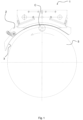
Figure 1 is a top plan view of an embodiment of a cutting apparatus made in accordance with the present invention; -
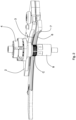
Figure 2 is a perspective view of a portion of the apparatus ofFigure 1 ; -
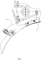
Figure 3 is a top plan view of a portion of the apparatus ofFigure 1 ; -
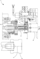
Figure 4 is a section, according to a vertical plane, of a portion of the apparatus ofFigure 1 ; -
Figure 5 shows an enlarged detail ofFigure 4 . - With reference to the aforementioned figures, with 1 a cutting apparatus has been indicated overall that is usable in a plant for producing capsules (in particular made of plastics) for closing containers, in particular for making the preferential weakening or fracture line, arranged between the closing portion of a capsule and the guarantee ring or band, to give rise to a security device that is able to bear witness to the first opening of the capsule.
- The
cutting apparatus 1 may comprise, in particular, at least oneabutting element 2 comprising at least one abutting surface configured in such a manner that a capsule C for closing containers can roll against the abutting surface along a rolling path. The abutting surface and the corresponding rolling path may have, as in this specific embodiment, a longitudinal extent substantially in the shape of a circular sector. - The
cutting apparatus 1 may comprise, in particular, at least oneblade 3 arranged on theabutting element 2 to perform a cut on a capsule C that rolls against the abutting surface to form a preferential line of fracture between a closing portion of the capsule C and a guarantee band of the capsule C. Theblade 3 may have, as in this specific embodiment, a longitudinal extent in the shape of a circular sector. Theblade 3 may comprise, in particular, any blade, also of known type, suitable for cutting the preferential line of fracture of a security device of a capsule for closing containers. - The
cutting apparatus 1 may comprise, in particular, at least onespindle 4 that is rotatable around its own rotation axis X. Thecutting apparatus 1 may comprise, in particular, at least onecarousel 5 rotating around a (vertical) rotation axis Y. Thecarousel 5 may carry a plurality ofspindles 4 arranged spaced apart from one another angularly. Eachspindle 4 is movable along a circular trajectory around the rotation axis Y of thecarousel 5 that carries thespindles 4. - Each
spindle 4 may be configured, in particular, to engage with at least one inner surface of a capsule C for containers. Eachspindle 4 is rotated around its own rotation axis X, for example by drive means controlled by (electronic and programmable) control means that controls the operation of thecutting apparatus 1. - Each
spindle 4 is movable along the rolling path, i.e. along a path parallel to the abutting surface so as to cause rolling of a respective capsule C when the capsule C is engaged, with a certain dragging force, between thespindle 4 and the abutting surface, in order for the cut to be performed on the capsule C to form the preferential fracture line. - The
cutting apparatus 1 may comprise, in particular, at least onecontact surface 6 made of plastics, which can be arranged on the abutting element 2 (in particular on the abutting surface, as in the illustrated embodiment) and/or on a side wall of the spindle 4 (in embodiments that are not illustrated), in such a manner that thecontact surface 6 is engageable in contact with a side wall of the capsule to cause the rolling by friction thereof. - In the specific embodiment, the
contact surface 6 made of plastics substantially constitutes the abutting surface of theabutting element 2, even if, as said, it is possible, in other embodiments that are not illustrated, that the contact surface made of plastics is arranged on an (outer) side wall of thespindle 4. - The
contact surface 6 may comprise or consist of at least one revolution surface sector (for example a cylindrical and/or conical surface) obtained by rotating a generating line around a rotation axis. The generating line may comprise, for example, a rectilinear segment (tilted or parallel to the rotation axis), or a curved segment, or a broken line, or a mixed curvilinear and rectilinear composite line, or a shaped line, etc.. Thecontact surface 6 may be formed in its entirety, or at least largely or predominantly (more than 50%), by at least one revolution surface sector. - The revolution surface may further comprise, in embodiments that are not illustrated, a surface extending longitudinally in a rectilinear or substantially rectilinear direction, which surface may be considered, from a theoretical geometric point of view, as in the particular case of a revolution surface obtained by rotating a generating line around a rotation axis placed at an infinite distance.
- In the illustrated embodiment, the
contact surface 6 in the form of a revolution surface sector is arranged on the abuttingelement 2. Thecontact surface 6 may extend, in particular, continuously along the rolling path or at least most of the rolling path. - In the illustrated embodiment the revolution surface is obtained by rotating a line around the rotation axis Y of the
carousel 5 that rotates thespindles 4. In other embodiments, which are not illustrated, thecontact surface 6 could be arranged on eachspindle 4 and the revolution surface (for example cylindrical) could be obtained by rotating a line around the rotation axis X of therespective spindle 4. - The
contact surface 6 may be arranged, in particular, on aninsert 7 arranged inside a recess of theabutting element 2. Theinsert 7 may be fixed removably to the abutting element 2 (for example by screw connection means as in this specific case). - The
carousel 5 may comprise, in particular, support means 8 to enable the capsules C to be supported whilst thespindles 4 engage the capsules C and roll the capsules C against theabutting element 2 and theblade 3. - The
cutting apparatus 1 may comprise, in particular, according to one embodiment that is not illustrated, at least one further contact surface made of plastics arranged on the abutting surface and/or on a side wall of the spindle. - The further contact surface made of plastics may be arranged, in particular, in such a manner as to be engageable in contact with a side wall of the capsule to supply a further friction surface to promote, in collaboration with the contact surface, rolling of the capsule by friction.
- The further contact surface may, in particular, extend in a manner substantially parallel to the contact surface. The further contact surface may be, in particular, spaced apart from the contact surface (in particular spaced in a vertical direction).
- The
contact surface 6 and/or the further contact surface may be made, in particular, of plastics that comprise ultra-high molecular weight polyethylene (UHMWPE). It is known that ultra-high molecular weight polyethylene UHMWPE has relatively high resistance to abrasion and relatively high impact strength. It has been moreover found that UHMWPE is particularly suitable for forming a contact surface (such as for example thecontact surface 6 and/or the further contact surface) that permits correct and effective rolling of the capsule (especially a capsule made of plastics, for example made of HDPE or of copolymer PP) during the cutting step for the formation of the preferential fracture line and, at the same time, permits appropriate processing of a high number of capsules, i.e. with a high working life of the surface. In particular, it is considered that the properties that make the UHMWPE a material that is particularly suitable for making the contact surface that permits correct rolling by friction of the capsule, could be the appropriate values of the dynamic friction coefficient and/or of the resistance to wear and/or hardness. - The plastics of the
contact surface 6 and/or of the further contact surface may comprise UHMWPE with the addition of additives (in particular additives that are suitable for improving the resistance to wear and/or slowing degradation and/or reduce the speed of oxidation of the material). The plastics of thecontact surface 6 and/or of the further contact surface may comprise, in particular, materials of the family of UHMWPE products that is known commercially as TIVAR®, more specifically (by way of example) the product TIVAR® H.OR.T.. - The
contact surface 6 may be processed, in particular, so as to have surface roughness Ra = 6.3 ± 3.0 µm (micrometres), or Ra > 1.6 µm and/or Ra < 12.5 µm, or the surface roughness Ra may be > 0.8 µm, or > 1.8 µm, or > 2.8 µm, or > 3.8 µm, or > 4.8 µm. The surface roughness Ra may be < 13.8 µm, or < 12.8 µm, or < 11.8 µm, or < 10.8 µm. - The
contact surface 6 may be made, in particular, of plastics with Shore hardness comprised between 48 and 68, or comprised between 50 and 66, or comprised between 52 and 64, or comprised between 54 and 62, or comprised between 56 and 60. The contact surface may be made, in particular, of plastics with a Shore hardness equal to 58 ± 5. - In the present description, the indicated Shore hardness values may be, in particular, values that are obtainable with measurements conducted with tests performed in accordance with standard ISO 868, performed in an environment at 23 °C, using testpieces measuring 10 mm in thickness (in particular removed from slabs that are 20-30 mm thick).
- The
contact surface 6 and/or the further contact surface may be made, in particular, of plastics with a dynamic friction coefficient of less than 0.50, or less than 0.45, or less than 0.40, or less than 0.35, measured by a tribo-system test on a pin made of plastics on a rotating steel disc. Thecontact surface 6 and/or the further contact surface may be made, in particular, of plastics with a dynamic friction coefficient that is greater than 0.10, or greater than 0.15, or greater than 0.20, or greater than 0.25, measured also in this case by a tribo-system test on a pin made of plastics on a rotating steel disc. - The
contact surface 6 and/or the further contact surface may be made, in particular, of plastics with a resistance to wear less than 20 µm/km, or less than 15 µm/km, or less than 10 µm/km, measured by a tribo-system test on a pin made of plastics on a rotating steel disc. - In the specific embodiment, the
contact surface 6 and/or the further contact surface may be made of plastics with a dynamic friction coefficient comprised between 0.15 and 0.30 and with a resistance to wear equal to about 6 µm/km, measured by a tribo-system test on a pin made of plastics on a rotating steel disc. - In the present description, it is understood that the indicated values relating to the dynamic friction coefficient and to resistance to wear are values that are obtainable from measurements conducted with tests performed on a pin made of plastics on a rotating steel disc (tribo-system), with the following test conditions: pressure: 3 MPa; sliding speed: 0.33 m/sec; surface roughness of the coupling surface made of C35 steel: Ra = 0.70 - 0.90 µm; total distance travelled: 28 km; normal environment (air 23 °C, relative humidity 50%), non-lubricated operation.
- The
contact surface 6 and/or the further contact surface may be made, in particular, of plastics with an elastic modulus greater than 600 MPa, or greater than 650 MPa. Thecontact surface 6 and/or the further contact surface may be made, in particular, of plastics with un elastic modulus less than 800 MPa, or less than 750 MPa. Thecontact surface 6 and/or the further contact surface may be made, in particular, of plastics with an elastic modulus equal to 700 ± 25 MPa. - In the present description, the indicated elastic modulus values may be, in particular, values obtainable from measurements conducted with tests performed in accordance with standard ISO 527-1/-2 with speeds equal to 1 mm/min.
- The operation of the
aforesaid cutting apparatus 1 implements a cutting method that comprises the step of engaging at least one capsule C for closing containers between therotatable spindle 4 and the abutting surface of theabutting element 2. - The cutting method may comprise, in particular, the step of moving the
spindle 4 along the abutting surface and simultaneously rotating thespindle 4 on itself so as to cause the capsule C to roll on the abutting surface of theabutting element 2. - The cutting method may comprise, in particular, the step of performing, during rolling of the capsule C, a cut on the capsule C by the fixed
blade 3 to form the preferential line of fracture between the closing portion of the capsule C and the guarantee band of the capsule C. - Rolling of the capsule C may occur, in particular, by friction at least against at least the
contact surface 6 made of plastics arranged on the abutting surface of theabutting element 2 and/or on a side wall of thespindle 4. Rolling of the capsule C could further occur by friction against at least the further contact surface made of plastics arranged on the abutting surface of abuttingelement 2 and/or on a side wall of thespindle 4. - Owing to the
contact surface 6 and/or the further contact surface, the cutting machining of the capsule C, which is suitable for forming the preferential line of fracture, can be performed on varying dimensions of the capsule C and/or of the shape of the possible knurling on the capsule C and/or of the pitch of the possible knurling on the capsule C, without the need to replace any component of thecutting apparatus 1, as the coupling that permits rolling does not occur through meshing of teeth of knurling, but through friction between a wall of the capsule C (provided with or devoid of knurling) and a contact surface that is suitable for any type of capsule C. - It is thus possible to ensure a correct cut also in the case of closing capsules C provided with knurls with teeth spaced far apart from one another and/or in the case of closing capsules C completely devoid of lateral knurling.
Claims (15)
- Cutting apparatus (1) comprising:- at least one abutting element (2) conformed and arranged so that a capsule (C) for closing containers can roll against said abutting element (2) along a rolling path;- at least one blade (3) arranged on said abutting element (2) to make a cut on a capsule (C) which rolls against said abutting element (2) to form a preferential fracture line between a closure portion of the capsule (C) and a guarantee band of the capsule (C);- at least one spindle (4) rotatable about its rotation axis (X), said spindle (4) being configured to engage with at least one inner surface of a capsule (C), said spindle (4) being movable along said abutting element (2) so as to cause the capsule (C) to roll when the latter is engaged between said spindle (4) and said abutting element (2), so that the cut is performed on the capsule (C) to form the preferential fracture line;characterized by comprising at least one contact surface (6) made of plastics arranged on said abutting element (2) so that said at least one contact surface (6) is engageable in contact with a side wall of the capsule (C); wherein said contact surface (6) is on an insert (7) that is arranged inside a recess of said abutting element (2) and/or wherein said contact surface (6) is on an insert (7) that is removably fixed to said abutting element (2).
- Cutting apparatus (1), comprising:- at least one abutting element (2) conformed and arranged so that a capsule (C) for closing containers can roll against said abutting element (2) along a rolling path;- at least one blade (3) arranged on said abutting element (2) to make a cut on a capsule (C) which rolls against said abutting element (2) to form a preferential fracture line between a closure portion of the capsule (C) and a guarantee band of the capsule (C);- at least one spindle (4) rotatable about its rotation axis (X), said spindle (4) being configured to engage with at least one inner surface of a capsule (C), said spindle (4) being movable along said abutting element (2) so as to cause the capsule (C) to roll when the latter is engaged between said spindle (4) and said abutting element (2), so that the cut is performed on the capsule (C) to form the preferential fracture line;characterized by comprising at least one contact surface (6) made of plastics arranged on said abutting element (2) and/or on a side wall of said spindle (4) so that said at least one contact surface (6) is engageable in contact with a side wall of the capsule (C).
- Apparatus according to claim 1 or 2, wherein said contact surface (6) is conformed as a revolution surface geometrically obtained by rotating a line around a rotation axis.
- Apparatus according to any one of the preceding claims, wherein said contact surface (6) is arranged on said abutting element (2) and extends continuously along said rolling path, said cutting apparatus (1) comprising at least one carousel (5) which rotates said spindle (4) about a rotation axis (Y).
- Apparatus according to any one of the preceding claims, wherein said plastics comprise ultra-high molecular weight polyethylene (UHMWPE).
- Apparatus according to any one of the preceding claims, wherein said at least one contact surface (6) is made of plastics with:- a surface roughness Ra = 6.3 ± 3.0 µm, or Ra > 1.6 µm and/or Ra < 12.5 µm, or Ra > 0.8 µm and/or Ra < 13.8 µm>; and/or- a Shore hardness between 48 and 68, or between 50 and 66, or between 52 and 64, or between 54 and 62, or between 56 and 60; and/or- a dynamic friction coefficient less than 0.50, or less than 0.45, or less than 0.40, or less than 0.35; and/or- a dynamic friction coefficient greater than 0.10, or greater than 0.15, or greater than 0.20, or greater than 0.25; and/or- a wear resistance of less than 20 µm/km, or less than 15 µm/km, or less than 10 µm/km, measured by a tribo-system test on a pin made of plastics on a rotating steel disk; and/or- an elastic modulus greater than 600 MPa, or greater than 650 MPa; and/or- an elastic modulus less than 800 Mpa, or less than 750 MPa.
- Apparatus according to any one of the preceding claims, comprising at least one further contact surface made of plastics arranged on said abutting element and/or on a side wall of said spindle and arranged so that said at least one further contact surface is engageable in contact with a side wall of the capsule (C).
- Apparatus according to claim 7, wherein said at least one further contact surface extends substantially parallel to said at least one contact surface (6) and is spaced from the latter.
- Cutting method comprising the steps of:- engaging a capsule (C) for closing containers between a rotating spindle (4) and an abutting element (2);- moving the spindle (4) along the abutting element (2) and simultaneously rotating the spindle (4) on itself so as to cause the capsule (C) to roll on the abutting element (2) along a rolling path;- during rolling, making a cut on the capsule (C) by means of a fixed blade (3) to form a preferential fracture line between a closing portion of the capsule and a guarantee band of the capsule;characterized in that said rolling occurs by friction against at least one contact surface (6) made of plastics arranged on said abutting element (2); wherein said contact surface (6) is on an insert (7) that is arranged inside a recess of said abutting element (2) and/or wherein said contact surface (6) is on an insert (7) that is removably fixed to said abutting element (2).
- Cutting method comprising the steps of:- engaging a capsule (C) for closing containers between a rotating spindle (4) and an abutting element (2);- moving the spindle (4) along the abutting element (2) and simultaneously rotating the spindle (4) on itself so as to cause the capsule (C) to roll on the abutting element (2) along a rolling path;- during rolling, making a cut on the capsule (C) by means of a fixed blade (3) to form a preferential fracture line between a closing portion of the capsule and a guarantee band of the capsule;characterized in that said rolling occurs by friction against at least one contact surface (6) made of plastics arranged on said abutting element (2) and/or on a side wall of said spindle (4).
- Method according to claim 9 or 10, wherein said contact surface (6) is conformed as a revolution surface geometrically obtained by rotating a line around a rotation axis.
- Method according to any one of claims 9 to 11, wherein said contact surface (6) is arranged on said abutting element (2) and extends continuously along said rolling path, said spindle (4) being rotated by a carousel (5) around a rotation axis (Y).
- Method according to any one of claims 9 to 12, wherein said at least one contact surface (6) is made of plastics comprising ultra-high molecular weight polyethylene (UHMWPE).
- Method according to any one of claims 9 to 13, wherein:- said at least one contact surface (6) is made of plastics with a wear resistance of less than 20 µm/km, or less than 15 µm/km, or less than 10 µm/km, measured with a tribo-system test on a pin made of plastics on a rotating steel disk; and/or- said at least one contact surface (6) is made of plastics with a Shore hardness of between 48 and 68, or between 50 and 66, or between 52 and 64, or between 54 and 62, or between 56 and 60.
- Method according to any one of claims 9 to 14, wherein:- said at least one contact surface (6) is made of plastics with a dynamic friction coefficient less than 0.50, or less than 0.45, or less than 0.40, or less than 0.35; and/or with a dynamic friction coefficient greater than 0.10, or greater than 0.15, or greater than 0.20, or greater than 0.25; and/or- said at least one contact surface (6) is made of plastics with an elastic modulus greater than 600 Mpa, or greater than 650 Mpa, and/or with an elastic modulus less than 800 Mpa, or less than 750 MPa.
Applications Claiming Priority (3)
| Application Number | Priority Date | Filing Date | Title |
|---|---|---|---|
| IT102018000010118A IT201800010118A1 (en) | 2018-11-07 | 2018-11-07 | APPARATUS AND METHOD OF CUTTING |
| EP19795674.1A EP3877123B1 (en) | 2018-11-07 | 2019-10-28 | Cutting apparatus and method |
| PCT/IB2019/059226 WO2020095145A1 (en) | 2018-11-07 | 2019-10-28 | Cutting apparatus and method |
Related Parent Applications (2)
| Application Number | Title | Priority Date | Filing Date |
|---|---|---|---|
| EP19795674.1A Division EP3877123B1 (en) | 2018-11-07 | 2019-10-28 | Cutting apparatus and method |
| EP19795674.1A Division-Into EP3877123B1 (en) | 2018-11-07 | 2019-10-28 | Cutting apparatus and method |
Publications (2)
| Publication Number | Publication Date |
|---|---|
| EP4570463A2 true EP4570463A2 (en) | 2025-06-18 |
| EP4570463A3 EP4570463A3 (en) | 2025-09-10 |
Family
ID=65409321
Family Applications (2)
| Application Number | Title | Priority Date | Filing Date |
|---|---|---|---|
| EP25162393.0A Pending EP4570463A3 (en) | 2018-11-07 | 2019-10-28 | Cutting apparatus and method |
| EP19795674.1A Active EP3877123B1 (en) | 2018-11-07 | 2019-10-28 | Cutting apparatus and method |
Family Applications After (1)
| Application Number | Title | Priority Date | Filing Date |
|---|---|---|---|
| EP19795674.1A Active EP3877123B1 (en) | 2018-11-07 | 2019-10-28 | Cutting apparatus and method |
Country Status (7)
| Country | Link |
|---|---|
| US (1) | US11577421B2 (en) |
| EP (2) | EP4570463A3 (en) |
| JP (1) | JP7217803B2 (en) |
| CN (1) | CN112888539B (en) |
| IT (1) | IT201800010118A1 (en) |
| TW (1) | TWI794553B (en) |
| WO (1) | WO2020095145A1 (en) |
Families Citing this family (1)
| Publication number | Priority date | Publication date | Assignee | Title |
|---|---|---|---|---|
| US12371235B2 (en) * | 2015-04-02 | 2025-07-29 | ThisCap, Inc. | Tool for manufacturing a cap for a container |
Citations (2)
| Publication number | Priority date | Publication date | Assignee | Title |
|---|---|---|---|---|
| WO2004004993A1 (en) | 2002-07-02 | 2004-01-15 | Sacmi Cooperativa Meccanici Imola S.C.R.L. | Apparatus for making a fracture cut between the cup and the safety ring in plastic caps |
| WO2011058500A1 (en) | 2009-11-10 | 2011-05-19 | Sacmi Cooperativa Meccanici Im0La Societa' Cooperativa | Cutting apparatus and method |
Family Cites Families (11)
| Publication number | Priority date | Publication date | Assignee | Title |
|---|---|---|---|---|
| JPS61287560A (en) * | 1985-05-31 | 1986-12-17 | 日本クラウンコルク株式会社 | Method and device for forming weakening line in vessel cover |
| IT1266234B1 (en) * | 1993-01-29 | 1996-12-27 | Sacmi | DEVICE FOR FORMING A FRACTURE INCISION IN THE GUARANTEE RING IN SCREW CAPS MADE OF PLASTIC MATERIAL. |
| JPH11288151A (en) * | 1998-04-03 | 1999-10-19 | Canon Inc | Image forming device |
| JP2000102604A (en) | 1998-09-29 | 2000-04-11 | Kyocera Corp | Centrifugal blood pump |
| CN2565759Y (en) * | 2002-07-31 | 2003-08-13 | 廖基地 | Bottle cap cutting machine |
| CN2647763Y (en) * | 2003-09-16 | 2004-10-13 | 陈艺力 | Bottle cap ring cutting machine |
| US20070089587A1 (en) * | 2005-10-26 | 2007-04-26 | Chi-Ti Liao | Mechanism making braking lines for container caps |
| ITMO20070333A1 (en) * | 2007-11-08 | 2009-05-09 | Sacmi | CAPSULE, APPARATUS AND METHOD |
| CN102922549A (en) * | 2012-10-17 | 2013-02-13 | 李红彪 | Hanging cap cutting tool structure |
| CN203792396U (en) * | 2014-03-10 | 2014-08-27 | 罗标荣 | Bottle cap ring cutting machine |
| ES2651340T3 (en) * | 2015-06-08 | 2018-01-25 | Bortolin Kemo S.P.A. | Bottle Cap Cutting Machine |
-
2018
- 2018-11-07 IT IT102018000010118A patent/IT201800010118A1/en unknown
-
2019
- 2019-10-28 EP EP25162393.0A patent/EP4570463A3/en active Pending
- 2019-10-28 JP JP2021524063A patent/JP7217803B2/en active Active
- 2019-10-28 US US17/291,704 patent/US11577421B2/en active Active
- 2019-10-28 CN CN201980069690.7A patent/CN112888539B/en active Active
- 2019-10-28 WO PCT/IB2019/059226 patent/WO2020095145A1/en not_active Ceased
- 2019-10-28 EP EP19795674.1A patent/EP3877123B1/en active Active
- 2019-10-30 TW TW108139250A patent/TWI794553B/en active
Patent Citations (2)
| Publication number | Priority date | Publication date | Assignee | Title |
|---|---|---|---|---|
| WO2004004993A1 (en) | 2002-07-02 | 2004-01-15 | Sacmi Cooperativa Meccanici Imola S.C.R.L. | Apparatus for making a fracture cut between the cup and the safety ring in plastic caps |
| WO2011058500A1 (en) | 2009-11-10 | 2011-05-19 | Sacmi Cooperativa Meccanici Im0La Societa' Cooperativa | Cutting apparatus and method |
Also Published As
| Publication number | Publication date |
|---|---|
| EP4570463A3 (en) | 2025-09-10 |
| TWI794553B (en) | 2023-03-01 |
| US11577421B2 (en) | 2023-02-14 |
| IT201800010118A1 (en) | 2020-05-07 |
| US20220001567A1 (en) | 2022-01-06 |
| EP3877123A1 (en) | 2021-09-15 |
| BR112021008416A2 (en) | 2021-09-14 |
| CN112888539A (en) | 2021-06-01 |
| JP7217803B2 (en) | 2023-02-03 |
| CN112888539B (en) | 2022-10-21 |
| JP2022506616A (en) | 2022-01-17 |
| EP3877123B1 (en) | 2025-05-28 |
| TW202027940A (en) | 2020-08-01 |
| WO2020095145A1 (en) | 2020-05-14 |
Similar Documents
| Publication | Publication Date | Title |
|---|---|---|
| EP2501511B1 (en) | Cutting edge geometry in rounded nose end mills | |
| US10040211B2 (en) | Power operated rotary knife | |
| US10857602B2 (en) | Dimples processing method by means of end milling and end mill | |
| EP3877123B1 (en) | Cutting apparatus and method | |
| EP2433735A1 (en) | A gear milling cutter as well as a replaceable milling insert therefor | |
| EP2832483B1 (en) | Ball end mill | |
| WO2010095249A1 (en) | Tap with drill | |
| EP3159087A1 (en) | Rotating cutting edge-type milling tool and cutting method using same | |
| JP5476267B2 (en) | Tap with drill | |
| CN104837587B (en) | Method for determining the flank profile of a hobbing tool | |
| WO2008140723A1 (en) | Tool for improved chip flow | |
| CA2938211A1 (en) | Stacked material tool and method for machining | |
| JP6723623B1 (en) | Cutting method | |
| JP2021506599A5 (en) | Threading insert with variable edge rounding | |
| DE102018118475B4 (en) | Cutting knives, high-speed slicers and methods for slicing food products | |
| US20240165840A1 (en) | Cutting device for cutting capsules | |
| JP7789791B2 (en) | Cutting device and method for cutting caps | |
| US20150117974A1 (en) | Method And Device For Machining Longitudinal Edges Of Metal Workpieces | |
| JPH0223313B2 (en) | ||
| BR112021008416B1 (en) | CUTTING APPARATUS AND METHOD | |
| JP2010125593A (en) | Tap for cutting | |
| SE532292C2 (en) | Screw with machining surface | |
| RU2685824C1 (en) | Cutter for rotary turning | |
| CA2325178A1 (en) | Circular punch | |
| MXPA00007295A (en) | Cutting tool for producing toothed articles |
Legal Events
| Date | Code | Title | Description |
|---|---|---|---|
| PUAI | Public reference made under article 153(3) epc to a published international application that has entered the european phase |
Free format text: ORIGINAL CODE: 0009012 |
|
| STAA | Information on the status of an ep patent application or granted ep patent |
Free format text: STATUS: THE APPLICATION HAS BEEN PUBLISHED |
|
| AC | Divisional application: reference to earlier application |
Ref document number: 3877123 Country of ref document: EP Kind code of ref document: P |
|
| AK | Designated contracting states |
Kind code of ref document: A2 Designated state(s): AL AT BE BG CH CY CZ DE DK EE ES FI FR GB GR HR HU IE IS IT LI LT LU LV MC MK MT NL NO PL PT RO RS SE SI SK SM TR |
|
| PUAL | Search report despatched |
Free format text: ORIGINAL CODE: 0009013 |
|
| AK | Designated contracting states |
Kind code of ref document: A3 Designated state(s): AL AT BE BG CH CY CZ DE DK EE ES FI FR GB GR HR HU IE IS IT LI LT LU LV MC MK MT NL NO PL PT RO RS SE SI SK SM TR |
|
| RIC1 | Information provided on ipc code assigned before grant |
Ipc: B26F 1/18 20060101AFI20250806BHEP |
|
| STAA | Information on the status of an ep patent application or granted ep patent |
Free format text: STATUS: REQUEST FOR EXAMINATION WAS MADE |
|
| 17P | Request for examination filed |
Effective date: 20251030 |