EP4570460A1 - Razor connector - Google Patents
Razor connector Download PDFInfo
- Publication number
- EP4570460A1 EP4570460A1 EP23216369.1A EP23216369A EP4570460A1 EP 4570460 A1 EP4570460 A1 EP 4570460A1 EP 23216369 A EP23216369 A EP 23216369A EP 4570460 A1 EP4570460 A1 EP 4570460A1
- Authority
- EP
- European Patent Office
- Prior art keywords
- actuator
- connector
- locking element
- retracting shaft
- handle
- Prior art date
- Legal status (The legal status is an assumption and is not a legal conclusion. Google has not performed a legal analysis and makes no representation as to the accuracy of the status listed.)
- Pending
Links
Images





Classifications
-
- B—PERFORMING OPERATIONS; TRANSPORTING
- B26—HAND CUTTING TOOLS; CUTTING; SEVERING
- B26B—HAND-HELD CUTTING TOOLS NOT OTHERWISE PROVIDED FOR
- B26B21/00—Razors of the open or knife type; Safety razors or other shaving implements of the planing type; Hair-trimming devices involving a razor-blade; Equipment therefor
- B26B21/40—Details or accessories
- B26B21/52—Handles, e.g. tiltable, flexible
-
- B—PERFORMING OPERATIONS; TRANSPORTING
- B26—HAND CUTTING TOOLS; CUTTING; SEVERING
- B26B—HAND-HELD CUTTING TOOLS NOT OTHERWISE PROVIDED FOR
- B26B21/00—Razors of the open or knife type; Safety razors or other shaving implements of the planing type; Hair-trimming devices involving a razor-blade; Equipment therefor
- B26B21/40—Details or accessories
- B26B21/52—Handles, e.g. tiltable, flexible
- B26B21/521—Connection details, e.g. connection to razor heads
Definitions
- the present disclosure relates to a connector for engaging a blade assembly to a razor handle, and a razor handle comprising the connector.
- Razors also known as safety razors
- Razors have a blade assembly that is permanently or removably attached to a razor handle which, in use, is oriented in shaving direction.
- Blade assemblies typically comprise one or more cutting members, each supporting a cutting element (blade), mounted perpendicular to the shaving direction.
- Blade assemblies are also typically provided with a guard (at a leading longitudinal side of the blade assembly in the shaving direction) and a cap (at a trailing longitudinal side of the blade assembly in the shaving direction). In use, a user holds the razor handle in the shaving direction and brings the blade assembly into contact with a portion of skin defining a shaving plane.
- the object of the present disclosure is to address these challenges by providing a connector that allows for easy replacement of the blade assembly when the blades become dull, while also providing the flexibility to accommodate various handle designs.
- the present disclosure relates to a connector for connecting a blade assembly to a razor handle as defined in claim 1, a razor handle as defined in claim 13 and a razor system as defined in claim 15.
- the dependent claims depict exemplary embodiments of the present disclosure.
- a connector for engaging a blade assembly to a razor handle comprises a connector body extending between a handle engaging portion and a blade assembly engaging portion along a longitudinal axis, the handle engaging portion comprising a retracting shaft, and a locking element coupled to the retracting shaft, wherein the actuator is configured to move the retracting shaft such that the locking element expands in an angled direction b with respect to the longitudinal axis A.
- the connector comprises a handle engaging portion with an actuator, a retracting shaft and a locking element (expanding and/or contracting mechanism), a blade assembly can be assembled to razor handles of any suitable shape, features, aesthetics, color and/or material in a secure and robust way.
- the connector may lead to less engineering complexity.
- tight tolerances and dimensional limitations of different razor handle materials may play no part since the expanding and/or contracting mechanism is utilized for the expansion and/or contraction of the handle engaging portion.
- the expanding and/or contracting mechanism can be configured to couple the connector to the razor handle by a non-positively locking connection, more specifically by a friction-locking connection.
- the connector is designed to securely connect a handle and a blade assembly together, while also allowing for quick and easy detachment of the blade assembly for replacement purposes.
- the connector is designed to be compatible with a variety of handle designs made of different materials, allowing users to select a handle that meets their individual preferences. This provides users with greater convenience, flexibility, and customization options.
- the connector comprises an actuator configured to move the retracting shaft so that the retracting shaft expands at least one locking element
- the actuator is a lever that is configured to move from a rest position to a locked position, such that when the lever is in the locked position, the locking element is expanded.
- the lever is rotatable along a rotation axis which is perpendicular to the longitudinal axis, when the lever moves from a rest position to a locked position or vice versa.
- the actuator is a rotating ring configured to move from a rest position to a locked position, wherein when the rotating ring is in the locked position the locking element is expanded.
- the actuator is a pushing or rotating element configured to engage with an inclined surface of the retracting shaft and move the retracting shaft from the rest position to the locked position.
- the pushing or rotating element is rotatable along a rotation axis which is parallel to the longitudinal axis, when the pushing or rotating element moves from a rest position to a locked position or vice versa.
- the locking element comprises an elastomeric portion.
- the locking element is located on the retracting shaft.
- the retracting shaft comprises a recess and wherein the locking element is a ring that is located on that recess.
- the actuator comprises at least one arm having a connection surface, wherein the connection surface has a cylindrical shape configured to mate with a cylindrical rotation pin of the retracting shaft, allowing the actuator to rotate over the rotation pin along a rotation axis.
- the connector comprises more than one locking element, for example two locking elements, one locking element located adjacent to the end of the retracting shaft and the other locking element located adjacent to the actuator.
- a sleeve may be arranged between the locking element and the actuator.
- the connector comprises a shaft carrier coupled to the retracting shaft, wherein the actuator during use, causes the shaft carrier to move the locking element along the longitudinal axis, thereby expanding the locking element in an angled direction b with respect to the longitudinal axis.
- the actuator comprises an engagement surface, so that when the actuator moves towards the locked position the actuator engagement surface engages with an engagement surface of the shaft carrier and thereby securing the actuator to the locked position.
- the connector further comprises a release button for disengaging a blade assembly from the blade assembly engaging portion.
- a razor handle may extend between a distal end and a proximal end, wherein the proximal end comprises a cavity for receiving the handle engaging portion of the connector.
- the cavity of the razor handle has a cylindrical shape.
- a razor system may comprise the blade assembly, the connector and the razor handle wherein the connector is configured to releasably connect the blade assembly and the razor handle.
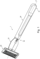
- Fig. 1 shows a schematic view of a razor system 1 and a connector 10 for connecting a blade assembly 20 to a razor handle 30 according to the present disclosure.
- the razor system 1 comprises a razor handle 30, a blade assembly 20 and a connector 10.
- the connector 10 can be coupled to the razor handle 30 and/or to the blade assembly 20.
- the blade assembly 20 can be releasably attached to the connector 10 via a pivotable or non-pivotable coupling.
- the blade assembly 20 is fixedly attached to the connector 10 via a pivotable or non-pivotable coupling.
- the connector 10 can be releasably coupled to the razor handle 30 and/or to the blade assembly 20.
- the connector 10 comprises a connector body 100, a blade assembly engaging portion 200 extending from the connector body 100 and a handle engaging portion 300 extending from the connector body 100 on the opposite direction with respect to the handle engaging portion 300.
- the blade assembly engaging portion 200 is configured to be coupled to the blade assembly 20.
- the handle engaging portion 300 is configured to be coupled to the razor handle 30.
- the handle engaging portion 200 comprises a retracting shaft 310.
- the handle engaging portion 200 further comprises an actuator 320 configured to move the retracting shaft 310 so that the retracting shaft 310 expands at least one locking element 330, adapted to expand towards an angled direction (b) with respect to the longitudinal axis A.
- the locking element 330 is arranged on the retracting shaft 310.
- the locking element 330 is arranged between the actuator 320 and the stop element 316. In examples the locking element 330 may be arranged between the shaft carrier 340 and the stop element 316.
- the retracting shaft 310 may comprise a stop element 316 which prevents the locking element 330 to be decoupled by the retracting shaft 310.
- the stop element 316 may be in the form of a protrusion extending perpendicularly from the longitudinal Axis A.
- the actuator 320 may be rotatably connected to the retracting shaft 310. In examples, the actuator 320 may further comprise at least one arm 322 (shown in Fig. 4A ) which comprises a connection surface 323.
- connection surface 323 may have a cylindrical shape configured to mate with a cylindrical rotation pin 315 of the retracting shaft, allowing the actuator 320 to rotate over the rotation pin 315 along the rotation axis x.
- the axis x may be substantially perpendicular to the longitudinal axis A.
- the connector 10 may further comprise a shaft carrier 340 arranged between the actuator 320 and the locking element 330 (as shown for example in fig. 2 ).
- the shaft carrier 340 may comprise an engagement surface 342.
- the actuator 320 may comprise an actuator engagement surface 327.
- the actuator engagement surface 327 may be substantially curved. A curved surface provides an easier and smoother actuation of the actuator compared for example to a plurality of angled surfaces.
- a locked position is considered to be the position of the actuator 320 where the locking element 330 is expanded thus the connector 10 is secured inside the handle's cavity 33.
- a rest position is considered to be the position of the actuator 320 where the locking element 330 is not expanded, thus the connector can be inserted or removed from the cavity 33 of the handle 30.
- the engagement surface 342 of the shaft carrier 340 may be substantially flat. This provides more safety and prevents any accidental disengagement between the handle 30 and the connector 10 during use. Additionally, the shaft carrier 340 transfers to the locking element 330 the force to expand provided by the actuator 320.
- the actuator moves the retracting shaft 310 along the longitudinal direction A, more specifically towards the proximal end 32 of the handle.
- the shaft carrier 340 compresses the locking element 330 so that the locking element 330 expands in an angled direction b with respect to the longitudinal axis A.
- the angled direction (b) may have an angle (f) of 0 to 90 degrees measured with respect to the longitudinal direction A.
- the angle (f) may be 90 degrees.
- the expansion may comprise a deformation of the locking element 330.
- the locking element 330 may comprise an elastomeric portion or may be made of any material that provides elasticity such that it can be deformed when the actuator is in the locked position and be able to return back to its original state when the actuator returns to the rest position.
- a sleeve 350 may be arranged in between the locking element 330 and the actuator 320.
- a sleeve 350 is arranged between the locking element 330 and the shaft carrier 340.
- the sleeve 350 may be a rigid, meaning a non-deformable element (made of a non-deformable material that resists deformation under forces that are created during coupling and de-coupling of the components) which extends along the longitudinal direction A.
- the sleeve may have the shape of a tube.
- the sleeve 350 may be free to move along the longitudinal direction A within the bounders of the retracting shaft.
- a blade assembly 20 can be assembled to razor handles 30 of any suitable shape, features, aesthetics, color and/or material in a secure and robust way.
- Connector 10 leads to less engineering complexity.
- tight tolerances and dimensional limitations of different razor handle materials play no part since the locking element 330 can be utilized for a safe connection of the handle engaging portion 300.
- the locking element 330 that is configured to expand, can compensate for tolerances between razor handle 30 and connector 10, more specifically between razor handle 30 and handle engaging portion 300.
- the following factors can have an influence on the tolerance requirements: material (including individual material characteristics of the assembled razor handle), precision, quality and environmental conditions of manufacturing, age and/or transportation of parts before assembly.
- the connector body 100 can be cylindrical or can have an oval, spherical, rectangular or polygonal shape (or cross-section). In embodiments, the connector body 100 can have an asymmetric shape (or cross-section).
- the handle engaging portion 300 can be integrally formed with the connector body 100 or can be connected to the connector body 100 by positively locking, non-positively locking and/or adhesive bond. The handle engaging portion 300 can be connected to a first connector body end face 102.
- a longitudinal axis A extends in the longitudinal direction of the connector 10 and through the geometric center of the connector 10.
- the connector 10 comprises a radial direction r, which is perpendicular to the longitudinal direction A.
- the connector 10 comprises a retracting shaft 310 connected to an actuator 320 configured to move the retracting shaft 310 so that the retracting shaft 310 expands at least one locking element 330, adapted to expand towards an angled direction b with respect to the longitudinal axis A, which is configured to couple the razor handle 30.
- the blade assembly engaging portion 200 can be integrally connected to the body portion 100.
- the blade assembly engaging portion 200 can be formed as a separate component and can be connected to the connector body 100 by a positively locking and/or non-positively locking connection.
- Figs. 1 to 4B are schematic views of the connector 10 according to a first embodiment.
- the handle engaging portion 300 comprises a length 1, a diameter d and an outer circumferential surface 390. More specifically, the handle engaging portion 300 is cylindrical. However, in embodiments, the handle engaging portion 300 may have a square-like or rectangular shape (or cross-section). In this case, the handle engaging portion 300 may have a cross-section having a width and a thickness instead of diameter d.
- the length 1 may be between 10 mm to 70 mm, more specifically between 15 mm to 60 mm, in particular between 20 mm to 50 mm.
- the diameter d may be between 0.5 mm to 20 mm, more specifically between 3 mm to 15 mm, in particular between 5 mm to 12 mm.
- the actuator 320 is a lever configured to rotate over a rotation axis x.
- the actuator 320 is rotatably connected to the retracting shaft 310. This means that the actuator 320 can move the retracting shaft between a rest and a locked position or vice versa. While moving to the locked position, the retracting shaft causes a locking element 330 to expand towards an angled direction b with respect to the longitudinal axis A. When the locking element 330 is expanded the connector 10 is safely secured to the razor handle 30.
- the actuator 320 may comprise a user engaging portion 320a configured to receive the user's hand so as trigger the actuator.
- the actuator 320 may further comprise at least one arm 322 (shown in Fig. 4A ) which comprises a connection surface 323. In examples, the actuator comprises two arms 322.
- the connection surface 323 may have a cylindrical shape configured to mate with a cylindrical rotation pin 315 of the retracting shaft, allowing the lever to rotate over the rotation pin 315 along the axis x.
- the retracting shaft 310 may comprise a recess 311 that extends from the outer circumferential surface 390 of the retracting shaft in the radial direction r.
- the recess 311 comprises a longitudinal shape extending substantially in the direction of the longitudinal axis x.
- the locking element 330 may be made of elastic material. When in contact with another component or surface, the locking element may provide increased friction force between the respective components.
- the locking element 330 may comprise a polymeric material having a shore hardness of 10 A to 60 A, in particular of 20 A to 50 A.
- the polymeric material may be an elastomer, a thermoplastic elastomer (TPE), rubber (synthetic or natural) or silicone. In embodiments, the polymeric material may be combined with additives.
- the additives may include one or more of plasticizers, oily compounds that improve rheological properties, fillers that improve mechanical properties and reduce costs, stabilizers that prevent certain chemical reactions, antistatic agents and/or colorants.
- the locking element 330 may be a material that can be expanded and/or contracted and is capable of regaining its original shape when the expanding and/or contraction force is no longer applied.
- the connector 10 can be manufactured by die-casting and/or moulding, and/or the locking element 330 can be manufactured by casting and/or injection moulding.
- the locking element 330 can be manufactured by extrusion, blow moulding, injection moulding, compacting / compaction, punching, plate pressing, rolling, calendering and/or die casting.
- the locking element 330 may be arranged in the recess 311 of the retracting shaft 310.
- the recess has a width, a length and a depth.
- the recess 311 is adapted to receive the locking element 330.
- the recess 311 may have a complementary shape with respect to the shape of the locking element 330.
- the recess 311 can be in the form of a circumferential groove on the outer circumferential surface 390 of the retracting shaft 310.
- the locking element 330 may have a tubular shape and the recess 311 may have a complementary shape to receive the locking element 330.
- the locking element can be provided as a sleeve that is disposed about the retracting shaft 310.
- the locking element 330 is configured to expand and/or contract in the radial direction r as will be described in more detail below.
- the recess 311 may comprise a complementary shape with respect to the shape of the locking element 330.
- a sleeve 350 may be provided, as shown in figs. 3A and 3B , located between the locking element 330 and the actuator 320. More specifically the sleeve 350 may be located between the shaft carrier 340 and the locking element 330. The sleeve may partially cover the retracting shaft 310.
- the sleeve 350 may be made from a rigid, meaning a non-deformable material that resists deformation under forces that are created during coupling and de-coupling of the components (i.e. ABS material) and can be used to transfer the longitudinal movement from the actuator 320 to the locking element 330.
- the locking element 330 when inserted into the recess 311, extends in the radial direction r up to the outer circumferential surface 390.
- the locking element 330 may extend below the circumferential surface 390 by a distance (not shown in figures) of at least 0.05 mm, more specifically by at least 0.10 mm, in particular by up to 0.30 mm, when the actuator 320 is in rest position.
- the locking element 330 may extend over the circumferential surface 390 by a distance (not shown in figures) of at least 0.05 mm, more specifically by at least 0.10 mm, in particular by up to 0.30 mm, when the actuator 320 is in locked position.
- the locking element comprises a length 11, which can be between 1 mm to 20 mm, more specifically between 2 mm to 15 mm, in particular 2 to 5mm. Furthermore, the locking element comprises a width w1, which can be between 0.2 mm to 15 mm, more specifically between 0.5 mm to 2 mm. An increased length 11 and/or width w1 of the locking element 330 may lead to a larger contact surface when coupled to the razor handle 30, thus increasing friction-force between the respective components/surfaces.
- the locking element 330 comprises an upper face 330a and a lower face 330b, wherein the upper face 330a and/or the lower face 330b have the length 11 and the width w1.
- the lower face 330b faces the retracting shaft 310 and the upper face 330a is the opposite face.
- the upper face 330a may further comprise texture or other surface features that increase friction in order to provide an even more secure connection.
- the locking element 330 may be elastic arranged in respective recess of the retracting shaft 310.
- the locking element 330 may be arranged partially or all around the retracting shaft 310 with respect to the circumferential direction or may be arranged on the outer circumferential surface 310 at different angles in the circumferential direction.
- the recess 311 extends in the radial direction r through the whole diameter d of the retracting shaft 310.
- the retracting shaft 310 comprises two locking elements 330, wherein a sleeve 350 is arranged between the two locking elements 330.
- the presence of two locking elements 330 provides an even more secure connection between the handle 30 and the connector 10.
- the at least one locking element comprises a diameter d1 that is larger than the diameter d of the retracting shaft 310.
- the diameter d1 can be at least 1.1 times larger than the diameter d.
- the diameter d1 can be at least 1.2 times larger than the diameter d.
- the locking element 330 is pressed against an inner surface 34 of the recess of the razor handle 30, as will be described in more detail below.
- the locking element 330 extends through the whole diameter d of the retracting shaft 310, the locking element can be pressed against the inner surface 34 on a circular distribution. This allows the pressure to be equally distributed on the material of the razor handle 30.
- the locking element 310 can have a cylindrical shape wherein increased friction force can be provided.
- the actuator 320 provides more pressure to the locking element 310, thus securing the retracting shaft 310 inside the cavity 33 of the razor handle 30.
- the locking element 330 may have a cross-section that tapers from the upper face 330a and/or lower face 330b towards a geometric center of the locking element 330.
- the recess may have a complementary shape.
- the locking element 330 can be retained in place when inserted into the recess 311 extending through the whole diameter d.
- the locking element 330 may comprise a plane which is parallel to the upper and/or lower faces 330a,330b and extends through the geometric center of locking element 330.
- the razor handle 30 comprises a cavity 33 with an inner surface 34, an inner diameter d2 and a length l2.
- the handle engaging portion 300 of the connector 10 can be inserted into the cavity 33.
- the inner diameter d2 may be larger than the diameter d of the retracting shaft 310 such that the handle engaging portion 300 can be inserted into the cavity 33 of the razor handle 30.
- the locking element 330 is configured to couple the connector 10 to the razor handle 30 by a non-positively locking connection, more specifically by a press-fit connection, in particular by a friction locking connection.
- the locking element 330 is adapted to expand and/or contract in the radial direction r perpendicular to the longitudinal axis x.
- the locking element 330 applies a force in the radial direction r against the inner surface 34 of the cavity 33.
- the locking element 330 may apply a force of at least 0.5 N, more specifically of at least 3 N, in particular of at least 5 N, in the radial direction r.
- the handle engaging portion 300 may be coupled to the razor handle 30 by a press-fit connection.
- a non-positively locking connection means that a normal force is applied on the surfaces to be coupled. Their mutual displacement is prevented as long as the counterforce caused by static friction is not exceeded. In other words, the surfaces of a non-positively locking connection only slip with respect to each other when a tangential force is greater than the static friction force occurring between the surfaces.
- the tangential force can be regarded as a force extending in the direction of the longitudinal axis x.
- the length l2 may be larger than the length l1 such that the first body portion end face 102 mates against a razor handle end face 35 when the connector is coupled to the razor handle.
- the first body portion end face 102 and the razor handle end face 35 may function as end collars forming a stop.
- the locking element 330 When inserted into the cavity 33 as shown in Figs. 3A to 3B , the locking element 330 can expand in the radial direction r in order to increase an effective diameter and/or to compensate for tolerances between the respective components, when the actuator 320 moves from the rest position to a lock position.
- the retracting shaft 310 moves along the longitudinal axis A and compresses the locking element 330 forcing it to expand towards the radial direction r, thus increasing its effective diameter d1.
- the locking element 330 extends beyond the outer circumferential surface 390 when the actuator is in the locked position.
- an outer diameter of the locking element 330 (see, e.g., d1) or a diameter measured between the handle engaging portion 300 and an outer face of the locking element 330 in the radial direction r may be larger than the inner diameter d2 of the cavity of the handle.
- the actuator 320 In order to insert the handle engaging portion 300 into the cavity 33 of the razor handle 30, the actuator 320 needs to be in the rest position and the locking element 330 shall not be expanded.
- the locking element 330 can be a polymeric material which is capable of regaining its original shape when contracted.
- the locking element 330 expands in the radial direction r and applies force against the inner surface 34, resulting in a coupling of handle engaging portion 300 and razor handle 30.
- Increasing the contact surfaces of the locking element 330 and the inner surface 34 e.g., by providing a plurality of locking elements 330 and/or increasing the length and/or the width of the locking elements 330, may lead to increased friction force and thus to a more stable coupling.
- Figs. 5 to 7 are schematic views of the connector 10' according to a second embodiment of the current disclosure, which can be combined with any of the features as described above.
- the handle engaging portion 300' comprises an actuator 320' configured to rotate along a rotation axis x' which is substantially parallel to the longitudinal axis A'.
- the actuator 320' is configured to move from a rest position to a locked position by the user.
- a push portion 320d' of the actuator 320' engages with an inclined surface 314' of the retracting shaft 310', and moves towards the longitudinal axis A'.
- This movement, of the retracting shaft 310' provides pressure on the locking element 330', thus expanding the locking element 330' in the radial direction r' and applies force against the inner surface 34', resulting in a coupling of handle engaging portion 300' and razor handle 30'.
- the actuator 320' may be rotatably connected to a shaft carrier 340'. When the actuator 320' is moved to the locked position, a pin 325' is inserted in a groove 341' of the shaft carrier 340'. The pin 325' and the groove 341' may have the same width, thus when they are engaged a friction connection is achieved.
- the inclined surface 314' of the retracting shaft 310' may comprise a lock cavity 315' adjacent to the inclined surface 314'.
- the actuator 320' moves to the locked position the pin 325' slides over the inclined surface 314' and falls into the lock cavity 315', where it is secured in order to avoid any accidental movement back to the rest position.
- This second embodiment comprises one locking element 330'. However, more than one locking elements 330' can be present, separated by a sleeve 350 as described in the first embodiment.
- Figs. 8 to 10 are schematic views of the connector 10" according to a third embodiment of the current disclosure.
- the handle engaging portion 300" comprises an actuator 320" configured to rotate along the longitudinal axis A".
- the actuator 320" comprises an inner groove 326" in which a pin 325" of the retracting shaft 310" extends.
- the actuator 320 is rotated towards the engagement direction.
- the inner groove 326 which has a helical shape like a thread, is mated with the pin 325" of the retracting shaft 310", thus moving the retracting shaft 310"along the longitudinal axis A".
- the retracting shaft 310 moves accordingly from the rest position to the locked position.
- the locking element 330 expands in the radial direction r" and applies force against the inner surface 34", resulting in a coupling of handle engaging portion 300" and the razor handle 30".
- the connector (10") comprises one locking element 330".
- more than one locking elements 330" can be contemplated without deviating from the scope and the teachings of the current disclosure.
- the more than one locking elements 330" may be also separated by a sleeve 350, as described in the first embodiment.
- the blade assembly engaging portion 200 may comprise a release mechanism 220.
- the release mechanism shall comprise a housing 230, a plunger 240, a first spring 250, a U-shaped ejector 260, a release button 210 and a second spring 270.
- the release mechanism is assembled at least partially inside connector body's recess 103. The user may actuate the release mechanism by pushing the release button 210 with his/her finger towards the longitudinal axis A. The release button 210 will compress the second spring 270. When pushed, the release button 210 is engaged with an inclined surface of the U-shaped ejector 260 and moves it along the longitudinal direction.
- the two arms 208 of the ejector push the blade assembly 20 and force it to decouple from the connector 10.
- the second spring 270 will provide a return force to the button to return to its rest position.
- the plunger 240 is connected to the U-shaped ejector 260 through a first spring 250.
- This connection provides a pivot force to the blade assembly 20 when connected to connector 10.
- the first spring 250 provides a return force to the U-shaped ejector 260 when the user no longer pushes the release button 210.
- the pivot mechanism described above may be adapted in any of the embodiments described in the description above.
Landscapes
- Life Sciences & Earth Sciences (AREA)
- Forests & Forestry (AREA)
- Engineering & Computer Science (AREA)
- Mechanical Engineering (AREA)
- Mutual Connection Of Rods And Tubes (AREA)
Abstract
A connector (10,10',10") for engaging a blade assembly (20) to a razor handle (30,30',30") comprising a connector body (100, 100', 100") extending between a handle engaging portion (300, 300', 300") and a blade assembly engaging portion (200) along a longitudinal axis (A, A', A") wherein the handle engaging portion (300, 300', 300") comprises a retracting shaft (310, 310', 310"), an actuator (320, 320',320") and a locking element (330,330',330") coupled to the retracting shaft (310,310',310") wherein the actuator (320,320',320") is configured to move the retracting shaft (310,310',310") such that the locking element (330,330',330"), expands in an angled direction (b) with respect to the longitudinal axis (A, A',A").
Description
- The present disclosure relates to a connector for engaging a blade assembly to a razor handle, and a razor handle comprising the connector.
- Razors (also known as safety razors) have a blade assembly that is permanently or removably attached to a razor handle which, in use, is oriented in shaving direction. Blade assemblies typically comprise one or more cutting members, each supporting a cutting element (blade), mounted perpendicular to the shaving direction. Blade assemblies are also typically provided with a guard (at a leading longitudinal side of the blade assembly in the shaving direction) and a cap (at a trailing longitudinal side of the blade assembly in the shaving direction). In use, a user holds the razor handle in the shaving direction and brings the blade assembly into contact with a portion of skin defining a shaving plane.
- In the field of razors, there are various razor models available on the market wherein the razor handles and/or blade assemblies differ in shape, features, aesthetics, color and/or material. On the one hand, there are razors having a blade assembly permanently attached to the razor handle, which may be disposed of when the razor blades are worn out. On the other hand, there are razors wherein the blade assembly is removably attached to the razor handle such that, when the razor blades are worn out, the blade assembly can be decoupled, disposed of, and replaced by a new blade assembly. The state of the art discloses various connection mechanisms for such razors, including snap-fit, threaded or magnetic connections. When a blade assembly is removably attached to a razor handle of a specific razor model, it may not be connectable to a razor handle of a different razor model. However, it would be desirable to be able to connect a blade assembly with different razor handles.
- Additionally, there is a growing demand for razors that can accommodate various handle designs and materials, providing consumers with greater customization options and improved ergonomics. Thus, every user will be able to gain an improved shaving experience by using a razor that fits well in his/her hand and provides safe handling during the shaving process. However, existing razor designs often lack the flexibility required to accommodate different handle designs.
- The object of the present disclosure is to address these challenges by providing a connector that allows for easy replacement of the blade assembly when the blades become dull, while also providing the flexibility to accommodate various handle designs.
- The present disclosure relates to a connector for connecting a blade assembly to a razor handle as defined in claim 1, a razor handle as defined in claim 13 and a razor system as defined in claim 15. The dependent claims depict exemplary embodiments of the present disclosure.
- According to a first aspect of the present disclosure, a connector for engaging a blade assembly to a razor handle comprises a connector body extending between a handle engaging portion and a blade assembly engaging portion along a longitudinal axis, the handle engaging portion comprising a retracting shaft, and a locking element coupled to the retracting shaft, wherein the actuator is configured to move the retracting shaft such that the locking element expands in an angled direction b with respect to the longitudinal axis A. Since the connector comprises a handle engaging portion with an actuator, a retracting shaft and a locking element (expanding and/or contracting mechanism), a blade assembly can be assembled to razor handles of any suitable shape, features, aesthetics, color and/or material in a secure and robust way. The connector may lead to less engineering complexity. Furthermore, tight tolerances and dimensional limitations of different razor handle materials may play no part since the expanding and/or contracting mechanism is utilized for the expansion and/or contraction of the handle engaging portion.
- The expanding and/or contracting mechanism can be configured to couple the connector to the razor handle by a non-positively locking connection, more specifically by a friction-locking connection.
- The connector is designed to securely connect a handle and a blade assembly together, while also allowing for quick and easy detachment of the blade assembly for replacement purposes.
- Furthermore, the connector is designed to be compatible with a variety of handle designs made of different materials, allowing users to select a handle that meets their individual preferences. This provides users with greater convenience, flexibility, and customization options.
- In embodiments, the connector comprises an actuator configured to move the retracting shaft so that the retracting shaft expands at least one locking element, wherein the actuator is a lever that is configured to move from a rest position to a locked position, such that when the lever is in the locked position, the locking element is expanded.
- In embodiments, the lever is rotatable along a rotation axis which is perpendicular to the longitudinal axis, when the lever moves from a rest position to a locked position or vice versa.
- In embodiments, the actuator is a rotating ring configured to move from a rest position to a locked position, wherein when the rotating ring is in the locked position the locking element is expanded.
- In embodiments, the actuator is a pushing or rotating element configured to engage with an inclined surface of the retracting shaft and move the retracting shaft from the rest position to the locked position.
- In embodiments, the pushing or rotating element is rotatable along a rotation axis which is parallel to the longitudinal axis, when the pushing or rotating element moves from a rest position to a locked position or vice versa.
- In embodiments, the locking element comprises an elastomeric portion.
- In embodiments, the locking element is located on the retracting shaft.
- In embodiments, the retracting shaft comprises a recess and wherein the locking element is a ring that is located on that recess.
- In embodiments, the actuator comprises at least one arm having a connection surface, wherein the connection surface has a cylindrical shape configured to mate with a cylindrical rotation pin of the retracting shaft, allowing the actuator to rotate over the rotation pin along a rotation axis.
- In embodiments, the connector comprises more than one locking element, for example two locking elements, one locking element located adjacent to the end of the retracting shaft and the other locking element located adjacent to the actuator.
- In embodiments, a sleeve may be arranged between the locking element and the actuator.
- In embodiments, the connector comprises a shaft carrier coupled to the retracting shaft, wherein the actuator during use, causes the shaft carrier to move the locking element along the longitudinal axis, thereby expanding the locking element in an angled direction b with respect to the longitudinal axis.
- In embodiments, the actuator comprises an engagement surface, so that when the actuator moves towards the locked position the actuator engagement surface engages with an engagement surface of the shaft carrier and thereby securing the actuator to the locked position.
- In embodiments, the connector further comprises a release button for disengaging a blade assembly from the blade assembly engaging portion.
- According to a second aspect of the present disclosure, a razor handle may extend between a distal end and a proximal end, wherein the proximal end comprises a cavity for receiving the handle engaging portion of the connector.
- In embodiments, the cavity of the razor handle has a cylindrical shape.
- According to a third aspect of the present disclosure, a razor system may comprise the blade assembly, the connector and the razor handle wherein the connector is configured to releasably connect the blade assembly and the razor handle.
- Additional objects, details and features of embodiments are described in reference to the drawings as follows.
- Other characteristics will be apparent from the accompanying drawings, which form a part of this disclosure. The drawings are intended to further explain the present disclosure and to enable a person skilled in the art to practice it. However, the drawings are intended as non-limiting examples. Common reference numerals on different figures indicate like or similar features.
-
Fig. 1 is a perspective view of a razor system. -
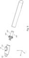
Fig.2 is a partial exploded view of the razor handle and the connector according to the first embodiment. -
Figs. 3A and 3B are side section views according to the first embodiment, in an unlocked and locked position. -
Fig. 4A is another partial exploded view of the razor handle and the connector. -
Fig. 4B is a section view of the connector engaged into the handle. -
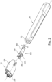
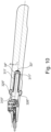
Fig.5 is a perspective view of the handle and the connector according to a second embodiment. -
Fig. 6 is a partial exploded view of the handle and the connector according to a second embodiment. -
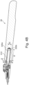
Fig. 7 is a side section view of the handle and the connector according to a second embodiment. -
Fig. 8 is a perspective view of the handle and the connector according to a third embodiment. -
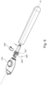
Fig. 9 is a partial exploded view of the handle and the connector according to a third embodiment. -
Fig. 10 is a side section view of the handle and the connector according to a third embodiment. -
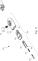
Fig. 11 is an exploded view of the blade assembly engaging portion of the connector. - Embodiments of the connector, the razor handle and the razor system according to the present disclosure will be described in reference to the drawings as follows:
Fig. 1 shows a schematic view of a razor system 1 and aconnector 10 for connecting ablade assembly 20 to arazor handle 30 according to the present disclosure. The razor system 1 comprises arazor handle 30, ablade assembly 20 and aconnector 10. Theconnector 10 can be coupled to the razor handle 30 and/or to theblade assembly 20. In embodiments, theblade assembly 20 can be releasably attached to theconnector 10 via a pivotable or non-pivotable coupling. In other embodiments, theblade assembly 20 is fixedly attached to theconnector 10 via a pivotable or non-pivotable coupling. As shown, e.g. inFig. 1 , theconnector 10 can be releasably coupled to the razor handle 30 and/or to theblade assembly 20. - Referring to
Figs. 2 to 4B , theconnector 10 comprises aconnector body 100, a bladeassembly engaging portion 200 extending from theconnector body 100 and ahandle engaging portion 300 extending from theconnector body 100 on the opposite direction with respect to thehandle engaging portion 300. The bladeassembly engaging portion 200 is configured to be coupled to theblade assembly 20. Thehandle engaging portion 300 is configured to be coupled to the razor handle 30. Thehandle engaging portion 200 comprises a retractingshaft 310. Thehandle engaging portion 200 further comprises anactuator 320 configured to move the retractingshaft 310 so that the retractingshaft 310 expands at least onelocking element 330, adapted to expand towards an angled direction (b) with respect to the longitudinal axis A. The lockingelement 330 is arranged on the retractingshaft 310. In examples, the lockingelement 330 is arranged between the actuator 320 and thestop element 316. In examples the lockingelement 330 may be arranged between theshaft carrier 340 and thestop element 316. The retractingshaft 310 may comprise astop element 316 which prevents the lockingelement 330 to be decoupled by the retractingshaft 310. Thestop element 316 may be in the form of a protrusion extending perpendicularly from the longitudinal Axis A. Theactuator 320 may be rotatably connected to the retractingshaft 310. In examples, theactuator 320 may further comprise at least one arm 322 (shown inFig. 4A ) which comprises aconnection surface 323. Theconnection surface 323 may have a cylindrical shape configured to mate with acylindrical rotation pin 315 of the retracting shaft, allowing theactuator 320 to rotate over therotation pin 315 along the rotation axis x. The axis x may be substantially perpendicular to the longitudinal axis A. - The
connector 10 may further comprise ashaft carrier 340 arranged between the actuator 320 and the locking element 330 (as shown for example infig. 2 ). Theshaft carrier 340 may comprise anengagement surface 342. Respectively, theactuator 320 may comprise anactuator engagement surface 327. Theactuator engagement surface 327 may be substantially curved. A curved surface provides an easier and smoother actuation of the actuator compared for example to a plurality of angled surfaces. When theactuator 320 moves towards the locked position, theactuator engagement surface 327 engages theengagement surface 342 of theshaft carrier 340 and secures theactuator 320 to the locked position. A locked position is considered to be the position of theactuator 320 where thelocking element 330 is expanded thus theconnector 10 is secured inside the handle'scavity 33. A rest position is considered to be the position of theactuator 320 where thelocking element 330 is not expanded, thus the connector can be inserted or removed from thecavity 33 of thehandle 30. Theengagement surface 342 of theshaft carrier 340 may be substantially flat. This provides more safety and prevents any accidental disengagement between thehandle 30 and theconnector 10 during use. Additionally, theshaft carrier 340 transfers to thelocking element 330 the force to expand provided by theactuator 320. When the user triggers theactuator 320, the actuator moves the retractingshaft 310 along the longitudinal direction A, more specifically towards theproximal end 32 of the handle. Theshaft carrier 340, compresses the lockingelement 330 so that the lockingelement 330 expands in an angled direction b with respect to the longitudinal axis A. The angled direction (b) may have an angle (f) of 0 to 90 degrees measured with respect to the longitudinal direction A. For example, the angle (f) may be 90 degrees. The expansion may comprise a deformation of thelocking element 330. Thus, the lockingelement 330 may comprise an elastomeric portion or may be made of any material that provides elasticity such that it can be deformed when the actuator is in the locked position and be able to return back to its original state when the actuator returns to the rest position. In between the lockingelement 330 and theactuator 320, asleeve 350 may be arranged. In examples, asleeve 350 is arranged between the lockingelement 330 and theshaft carrier 340. Thesleeve 350 may be a rigid, meaning a non-deformable element (made of a non-deformable material that resists deformation under forces that are created during coupling and de-coupling of the components) which extends along the longitudinal direction A. The sleeve may have the shape of a tube. Thesleeve 350 may be free to move along the longitudinal direction A within the bounders of the retracting shaft. - Since the
connector 10 comprises the bladeassembly engaging portion 200, ablade assembly 20 can be assembled to razor handles 30 of any suitable shape, features, aesthetics, color and/or material in a secure and robust way.Connector 10 leads to less engineering complexity. Furthermore, tight tolerances and dimensional limitations of different razor handle materials play no part since the lockingelement 330 can be utilized for a safe connection of thehandle engaging portion 300. In other words, the lockingelement 330 that is configured to expand, can compensate for tolerances between razor handle 30 andconnector 10, more specifically between razor handle 30 and handle engagingportion 300. However, apart from the respective geometries, the following factors can have an influence on the tolerance requirements: material (including individual material characteristics of the assembled razor handle), precision, quality and environmental conditions of manufacturing, age and/or transportation of parts before assembly. - In embodiments, the
connector body 100 can be cylindrical or can have an oval, spherical, rectangular or polygonal shape (or cross-section). In embodiments, theconnector body 100 can have an asymmetric shape (or cross-section). Thehandle engaging portion 300 can be integrally formed with theconnector body 100 or can be connected to theconnector body 100 by positively locking, non-positively locking and/or adhesive bond. Thehandle engaging portion 300 can be connected to a first connectorbody end face 102. - As shown in
Fig. 2 , a longitudinal axis A extends in the longitudinal direction of theconnector 10 and through the geometric center of theconnector 10. Furthermore, theconnector 10 comprises a radial direction r, which is perpendicular to the longitudinal direction A. Furthermore, theconnector 10 comprises a retractingshaft 310 connected to anactuator 320 configured to move the retractingshaft 310 so that the retractingshaft 310 expands at least onelocking element 330, adapted to expand towards an angled direction b with respect to the longitudinal axis A, which is configured to couple the razor handle 30. - In embodiments, the blade
assembly engaging portion 200 can be integrally connected to thebody portion 100. Alternatively, the bladeassembly engaging portion 200 can be formed as a separate component and can be connected to theconnector body 100 by a positively locking and/or non-positively locking connection. -
Figs. 1 to 4B are schematic views of theconnector 10 according to a first embodiment. Thehandle engaging portion 300 comprises a length 1, a diameter d and an outercircumferential surface 390. More specifically, thehandle engaging portion 300 is cylindrical. However, in embodiments, thehandle engaging portion 300 may have a square-like or rectangular shape (or cross-section). In this case, thehandle engaging portion 300 may have a cross-section having a width and a thickness instead of diameter d. The length 1 may be between 10 mm to 70 mm, more specifically between 15 mm to 60 mm, in particular between 20 mm to 50 mm. The diameter d may be between 0.5 mm to 20 mm, more specifically between 3 mm to 15 mm, in particular between 5 mm to 12 mm. - According to the first embodiment, the
actuator 320 is a lever configured to rotate over a rotation axis x. Theactuator 320 is rotatably connected to the retractingshaft 310. This means that theactuator 320 can move the retracting shaft between a rest and a locked position or vice versa. While moving to the locked position, the retracting shaft causes alocking element 330 to expand towards an angled direction b with respect to the longitudinal axis A. When thelocking element 330 is expanded theconnector 10 is safely secured to the razor handle 30. Theactuator 320 may comprise auser engaging portion 320a configured to receive the user's hand so as trigger the actuator. Theactuator 320 may further comprise at least one arm 322 (shown inFig. 4A ) which comprises aconnection surface 323. In examples, the actuator comprises twoarms 322. Theconnection surface 323 may have a cylindrical shape configured to mate with acylindrical rotation pin 315 of the retracting shaft, allowing the lever to rotate over therotation pin 315 along the axis x. - The retracting
shaft 310 may comprise arecess 311 that extends from the outercircumferential surface 390 of the retracting shaft in the radial direction r. Therecess 311 comprises a longitudinal shape extending substantially in the direction of the longitudinal axis x. The lockingelement 330 may be made of elastic material. When in contact with another component or surface, the locking element may provide increased friction force between the respective components. The lockingelement 330 may comprise a polymeric material having a shore hardness of 10 A to 60 A, in particular of 20 A to 50 A. The polymeric material may be an elastomer, a thermoplastic elastomer (TPE), rubber (synthetic or natural) or silicone. In embodiments, the polymeric material may be combined with additives. Amongst others, the additives may include one or more of plasticizers, oily compounds that improve rheological properties, fillers that improve mechanical properties and reduce costs, stabilizers that prevent certain chemical reactions, antistatic agents and/or colorants. The lockingelement 330 may be a material that can be expanded and/or contracted and is capable of regaining its original shape when the expanding and/or contraction force is no longer applied. In embodiments, theconnector 10 can be manufactured by die-casting and/or moulding, and/or thelocking element 330 can be manufactured by casting and/or injection moulding. In embodiments, the lockingelement 330 can be manufactured by extrusion, blow moulding, injection moulding, compacting / compaction, punching, plate pressing, rolling, calendering and/or die casting. - Referring to
Figs. 3A and 3B , the lockingelement 330 may be arranged in therecess 311 of the retractingshaft 310. The recess has a width, a length and a depth. Therecess 311 is adapted to receive thelocking element 330. In other words, therecess 311 may have a complementary shape with respect to the shape of thelocking element 330. In embodiments therecess 311 can be in the form of a circumferential groove on the outercircumferential surface 390 of the retractingshaft 310. In this case, the lockingelement 330 may have a tubular shape and therecess 311 may have a complementary shape to receive thelocking element 330. In examples, the locking element can be provided as a sleeve that is disposed about the retractingshaft 310. The lockingelement 330 is configured to expand and/or contract in the radial direction r as will be described in more detail below. Therecess 311 may comprise a complementary shape with respect to the shape of thelocking element 330. In examples, asleeve 350 may be provided, as shown infigs. 3A and 3B , located between the lockingelement 330 and theactuator 320. More specifically thesleeve 350 may be located between theshaft carrier 340 and thelocking element 330. The sleeve may partially cover the retractingshaft 310. Thesleeve 350 may be made from a rigid, meaning a non-deformable material that resists deformation under forces that are created during coupling and de-coupling of the components (i.e. ABS material) and can be used to transfer the longitudinal movement from theactuator 320 to thelocking element 330. - The locking
element 330, when inserted into therecess 311, extends in the radial direction r up to the outercircumferential surface 390. In embodiments, the lockingelement 330 may extend below thecircumferential surface 390 by a distance (not shown in figures) of at least 0.05 mm, more specifically by at least 0.10 mm, in particular by up to 0.30 mm, when theactuator 320 is in rest position. The lockingelement 330 may extend over thecircumferential surface 390 by a distance (not shown in figures) of at least 0.05 mm, more specifically by at least 0.10 mm, in particular by up to 0.30 mm, when theactuator 320 is in locked position. The locking element comprises alength 11, which can be between 1 mm to 20 mm, more specifically between 2 mm to 15 mm, in particular 2 to 5mm. Furthermore, the locking element comprises a width w1, which can be between 0.2 mm to 15 mm, more specifically between 0.5 mm to 2 mm. An increasedlength 11 and/or width w1 of thelocking element 330 may lead to a larger contact surface when coupled to the razor handle 30, thus increasing friction-force between the respective components/surfaces. The lockingelement 330 comprises anupper face 330a and alower face 330b, wherein theupper face 330a and/or thelower face 330b have thelength 11 and the width w1. Thelower face 330b faces the retractingshaft 310 and theupper face 330a is the opposite face. Theupper face 330a may further comprise texture or other surface features that increase friction in order to provide an even more secure connection. - In embodiments, there are two locking elements separated by the
sleeve 350. In embodiments, the lockingelement 330 may be elastic arranged in respective recess of the retractingshaft 310. The lockingelement 330 may be arranged partially or all around the retractingshaft 310 with respect to the circumferential direction or may be arranged on the outercircumferential surface 310 at different angles in the circumferential direction. - In embodiments, the
recess 311 extends in the radial direction r through the whole diameter d of the retractingshaft 310. In this case, the retractingshaft 310 comprises two lockingelements 330, wherein asleeve 350 is arranged between the two lockingelements 330. The presence of two lockingelements 330 provides an even more secure connection between thehandle 30 and theconnector 10. The at least one locking element comprises a diameter d1 that is larger than the diameter d of the retractingshaft 310. In embodiments, the diameter d1 can be at least 1.1 times larger than the diameter d. In particular, the diameter d1 can be at least 1.2 times larger than the diameter d. In case the retractingshaft 310 is coupled to the razor handle 30, the lockingelement 330 is pressed against aninner surface 34 of the recess of the razor handle 30, as will be described in more detail below. When thelocking element 330 extends through the whole diameter d of the retractingshaft 310, the locking element can be pressed against theinner surface 34 on a circular distribution. This allows the pressure to be equally distributed on the material of the razor handle 30. The lockingelement 310 can have a cylindrical shape wherein increased friction force can be provided. Theactuator 320 provides more pressure to thelocking element 310, thus securing the retractingshaft 310 inside thecavity 33 of the razor handle 30. - Referring to
Fig. 4B thelocking element 330 may have a cross-section that tapers from theupper face 330a and/orlower face 330b towards a geometric center of thelocking element 330. The recess may have a complementary shape. Thus, the lockingelement 330 can be retained in place when inserted into therecess 311 extending through the whole diameter d. The lockingelement 330 may comprise a plane which is parallel to the upper and/orlower faces element 330. - As shown in
Fig. 4A ,recess 311 comprises a complementary shape with respect to the shape of thelocking element 330. The cross-section of therecess 311 may taper from the outercircumferential surface 390 in the radial direction r towards the longitudinal axis A on each side. Therecess 311 may taper perpendicularly from the outercircumferential surface 390. Due to the taper that extends between longitudinal axis A and outercircumferential surface 390, the lockingelement 330 can be held in place. The retractingshaft 310 can be manufactured by die cast or injection molding. Therecess 311 can be made directly by the opening directions of the mold, thereby simplifying the molding operations and consequently the manufacturing process. - As shown in
Figs. 2 to 4B , the razor handle 30 comprises acavity 33 with aninner surface 34, an inner diameter d2 and a length l2. Thehandle engaging portion 300 of theconnector 10 can be inserted into thecavity 33. The inner diameter d2 may be larger than the diameter d of the retractingshaft 310 such that thehandle engaging portion 300 can be inserted into thecavity 33 of the razor handle 30. The lockingelement 330 is configured to couple theconnector 10 to the razor handle 30 by a non-positively locking connection, more specifically by a press-fit connection, in particular by a friction locking connection. The lockingelement 330 is adapted to expand and/or contract in the radial direction r perpendicular to the longitudinal axis x. When the actuator is triggered, the lockingelement 330 applies a force in the radial direction r against theinner surface 34 of thecavity 33. In an embodiment, the lockingelement 330 may apply a force of at least 0.5 N, more specifically of at least 3 N, in particular of at least 5 N, in the radial direction r. Thehandle engaging portion 300 may be coupled to the razor handle 30 by a press-fit connection. A non-positively locking connection means that a normal force is applied on the surfaces to be coupled. Their mutual displacement is prevented as long as the counterforce caused by static friction is not exceeded. In other words, the surfaces of a non-positively locking connection only slip with respect to each other when a tangential force is greater than the static friction force occurring between the surfaces. In the present case, the tangential force can be regarded as a force extending in the direction of the longitudinal axis x. In embodiments, the length l2 may be larger than the length l1 such that the first bodyportion end face 102 mates against a razorhandle end face 35 when the connector is coupled to the razor handle. In other words, the first bodyportion end face 102 and the razor handleend face 35 may function as end collars forming a stop. - When inserted into the
cavity 33 as shown inFigs. 3A to 3B , the lockingelement 330 can expand in the radial direction r in order to increase an effective diameter and/or to compensate for tolerances between the respective components, when theactuator 320 moves from the rest position to a lock position. Upon the movement of the actuator to the lock position, the retractingshaft 310 moves along the longitudinal axis A and compresses the lockingelement 330 forcing it to expand towards the radial direction r, thus increasing its effective diameter d1. According to the first embodiment, the lockingelement 330 extends beyond the outercircumferential surface 390 when the actuator is in the locked position. Thereby, an outer diameter of the locking element 330 (see, e.g., d1) or a diameter measured between thehandle engaging portion 300 and an outer face of thelocking element 330 in the radial direction r may be larger than the inner diameter d2 of the cavity of the handle. In order to insert thehandle engaging portion 300 into thecavity 33 of the razor handle 30, theactuator 320 needs to be in the rest position and thelocking element 330 shall not be expanded. As described above, the lockingelement 330 can be a polymeric material which is capable of regaining its original shape when contracted. Thus, when inserted into thecavity 33 and theactuator 320 is moved to the locked position, the lockingelement 330 expands in the radial direction r and applies force against theinner surface 34, resulting in a coupling ofhandle engaging portion 300 and razor handle 30. Increasing the contact surfaces of thelocking element 330 and theinner surface 34, e.g., by providing a plurality of lockingelements 330 and/or increasing the length and/or the width of the lockingelements 330, may lead to increased friction force and thus to a more stable coupling. -
Figs. 5 to 7 are schematic views of the connector 10' according to a second embodiment of the current disclosure, which can be combined with any of the features as described above. The handle engaging portion 300' comprises an actuator 320' configured to rotate along a rotation axis x' which is substantially parallel to the longitudinal axis A'. The actuator 320' is configured to move from a rest position to a locked position by the user. When the actuator 320' is moved to the locked position (not shown in figures), apush portion 320d' of the actuator 320' engages with an inclined surface 314' of the retracting shaft 310', and moves towards the longitudinal axis A'. This movement of the actuator 320' along with its engagement with the inclined surface 314' of the retracting shaft 310', causes the retracting shaft to move longitudinally along the longitudinal axis A' towards a proximal end 32'. This movement, of the retracting shaft 310' provides pressure on the locking element 330', thus expanding the locking element 330' in the radial direction r' and applies force against the inner surface 34', resulting in a coupling of handle engaging portion 300' and razor handle 30'. The actuator 320' may be rotatably connected to ashaft carrier 340'. When the actuator 320' is moved to the locked position, a pin 325' is inserted in a groove 341' of theshaft carrier 340'. The pin 325' and the groove 341' may have the same width, thus when they are engaged a friction connection is achieved. - As shown in
figure 7 the inclined surface 314' of the retracting shaft 310', may comprise a lock cavity 315' adjacent to the inclined surface 314'. When the actuator 320' moves to the locked position the pin 325' slides over the inclined surface 314' and falls into the lock cavity 315', where it is secured in order to avoid any accidental movement back to the rest position. - This second embodiment comprises one locking element 330'. However, more than one locking elements 330' can be present, separated by a
sleeve 350 as described in the first embodiment. -
Figs. 8 to 10 are schematic views of theconnector 10" according to a third embodiment of the current disclosure. Thehandle engaging portion 300" comprises anactuator 320" configured to rotate along the longitudinal axis A". Theactuator 320" comprises aninner groove 326" in which apin 325" of the retractingshaft 310" extends. When a user wants to engage theconnector 10" with the razor handle 30", theactuator 320" is rotated towards the engagement direction. During that operation theinner groove 326", which has a helical shape like a thread, is mated with thepin 325" of the retractingshaft 310", thus moving the retractingshaft 310"along the longitudinal axis A". When theactuator 320" is moved from the rest position towards the locked position (not shown in figures), the retractingshaft 310" moves accordingly from the rest position to the locked position. In the locked position, the lockingelement 330" expands in the radial direction r" and applies force against theinner surface 34", resulting in a coupling ofhandle engaging portion 300" and the razor handle 30". - The connector (10") comprises one
locking element 330". However, more than one lockingelements 330" can be contemplated without deviating from the scope and the teachings of the current disclosure. The more than one lockingelements 330" may be also separated by asleeve 350, as described in the first embodiment. - Referring to
Fig. 11 the bladeassembly engaging portion 200 may comprise arelease mechanism 220. The release mechanism shall comprise ahousing 230, aplunger 240, afirst spring 250, aU-shaped ejector 260, arelease button 210 and asecond spring 270. The release mechanism is assembled at least partially inside connector body'srecess 103. The user may actuate the release mechanism by pushing therelease button 210 with his/her finger towards the longitudinal axis A. Therelease button 210 will compress thesecond spring 270. When pushed, therelease button 210 is engaged with an inclined surface of theU-shaped ejector 260 and moves it along the longitudinal direction. The twoarms 208 of the ejector push theblade assembly 20 and force it to decouple from theconnector 10. When the user removes his/her finger from therelease button 210, thesecond spring 270 will provide a return force to the button to return to its rest position. The release mechanism described above may be adapted in any of the embodiments described in the description above. - The
plunger 240 is connected to theU-shaped ejector 260 through afirst spring 250. This connection provides a pivot force to theblade assembly 20 when connected toconnector 10. In addition to that thefirst spring 250 provides a return force to theU-shaped ejector 260 when the user no longer pushes therelease button 210. The pivot mechanism described above may be adapted in any of the embodiments described in the description above.
Claims (15)
- A connector (10,10',10") for engaging a blade assembly (20) to a razor handle (30,30',30") comprising:- a connector body (100, 100', 100") extending between a handle engaging portion (300, 300', 300") and a blade assembly engaging portion (200) along a longitudinal axis (A, A', A");wherein the handle engaging portion (300, 300', 300") comprises:- a retracting shaft (310, 310', 310")- an actuator (320, 320',320")- a locking element (330,330',330") coupled to the retracting shaft (310,310',310")wherein the actuator (320,320', 320") is configured to move the retracting shaft (310,310', 310") such that the locking element (330,330',330"), expands in an angled direction (b) with respect to the longitudinal axis (A, A', A").
- The connector (10) of claims 1 or 2, wherein the actuator (320) is a lever that is configured to move from a rest position to a locked position, wherein when the lever is in the locked position the locking element (330) is expanded.
- The connector (10) of claim 2, wherein the actuator (320) is rotatable along a rotation axis (x) which is perpendicular to the longitudinal axis (A), when the actuator moves from the rest position to the locked position or vice versa.
- The connector (10") of claim 1, wherein the actuator (320") is a rotating ring configured to move from a rest position to a locked position, wherein when the rotating ring is in the locked position the locking element (330") is expanded.
- The connector (10') of claim 1, wherein the actuator (320') is a pushing or rotating element configured to engage with an inclined surface (314') of the retracting shaft (310') and move the retracting shaft (310') from a rest position to a locked position.
- The connector (10,10',10") of claims 1 to 3, wherein the actuator (320) comprises at least one arm (322) having a connection surface (323), wherein the connection surface (323) has a cylindrical shape configured to mate with a cylindrical rotation pin (315) of the retracting shaft (310), thereby allowing the actuator (320) to rotate over the rotation pin (315) along a rotation axis (x).
- The connector (10,10',10") of claims 1 to 6, wherein the retracting shaft (330,330',330") comprises a recess (311,311',311") and wherein the locking element (330,330',330") is located in the recess (311,311',311").
- The connector (10,10',10") of claims 1 to 7 comprising two locking elements (330,330',330"), wherein a first locking element is arranged adjacent to an end of the retracting shaft (310,310',310") and the other locking element (330,330',330") is arranged adjacent to the actuator (320,320',320").
- The connector (10,10',10") of any of claims 1 to 8, further comprising a sleeve (350) located between the locking element (330) and the actuator (320), wherein the sleeve is made of a rigid material.
- The connector (10) of any of claims 1 to 3, further comprising a shaft carrier (340) coupled to the retracting shaft (310), wherein the actuator (320) during use, causes the shaft carrier (340) to move the locking element (330) along the longitudinal axis (A), thereby expanding the locking element (330) in an angled direction with respect to the longitudinal axis (A).
- The connector (10) of claim 10, wherein the actuator (320) comprises an actuator engagement surface (327), so that when the actuator (320) moves towards the locked position, the actuator engagement surface (327) engages with the engagement surface (342) of the shaft carrier (340) thereby securing the actuator to the locked position.
- The connector (10,10',10") of any of the preceding claims, further comprising a stop element (316) located at the end of the retracting shaft (310,310',310") which is opposite to the end adjacent to the actuator (320,320',320"), wherein the stop element (316) prevents the locking element (330,330',330") from being decoupled by the retracting shaft (310,310',310").
- A razor handle (30,30',30") extending between a distal end (31,31',31") and a proximal end (32,32',32"), wherein the proximal end (32,32',32") comprises a cavity (33,33',33") for receiving the handle engaging portion (300,300',300") of the connector (10,10',10") of any of the preceding claims.
- The razor handle (30,30,30',30") according to the preceding claim, wherein the cavity (33,33',33") has a cylindrical shape.
- A razor system (1) comprising:- a blade assembly (20);- the connector (10,10',10") of any of claims 1 to 12;- the razor handle (30,30',30") of any of claims 13 to 14;wherein the connector (10,10',10") is configured to releasably connect the blade assembly (20) and the razor handle (30,30',30").
Priority Applications (3)
| Application Number | Priority Date | Filing Date | Title |
|---|---|---|---|
| EP23216369.1A EP4570460A1 (en) | 2023-12-13 | 2023-12-13 | Razor connector |
| PCT/EP2024/084303 WO2025124964A1 (en) | 2023-12-13 | 2024-12-02 | Razor connector |
| CN202480076339.1A CN122319063A (en) | 2023-12-13 | 2024-12-02 | Razor connector |
Applications Claiming Priority (1)
| Application Number | Priority Date | Filing Date | Title |
|---|---|---|---|
| EP23216369.1A EP4570460A1 (en) | 2023-12-13 | 2023-12-13 | Razor connector |
Publications (1)
| Publication Number | Publication Date |
|---|---|
| EP4570460A1 true EP4570460A1 (en) | 2025-06-18 |
Family
ID=89222592
Family Applications (1)
| Application Number | Title | Priority Date | Filing Date |
|---|---|---|---|
| EP23216369.1A Pending EP4570460A1 (en) | 2023-12-13 | 2023-12-13 | Razor connector |
Country Status (3)
| Country | Link |
|---|---|
| EP (1) | EP4570460A1 (en) |
| CN (1) | CN122319063A (en) |
| WO (1) | WO2025124964A1 (en) |
Citations (5)
| Publication number | Priority date | Publication date | Assignee | Title |
|---|---|---|---|---|
| GB888738A (en) * | 1958-05-17 | 1962-02-07 | Heinz Osberghaus | Improvements in or relating to razors |
| EP1115537A1 (en) * | 1998-09-24 | 2001-07-18 | Tritec International Corporation | Adapter unit for a shaving razor |
| US20080086899A1 (en) * | 2006-10-12 | 2008-04-17 | Gallagher Richard N | Razor head and method for making the same |
| US20200223082A1 (en) * | 2014-10-07 | 2020-07-16 | Ruairidh Robertson | Shaving Device |
| EP4011573A1 (en) * | 2020-12-14 | 2022-06-15 | BIC Violex Single Member S.A. | Connector for connecting a razor head to a razor handle |
-
2023
- 2023-12-13 EP EP23216369.1A patent/EP4570460A1/en active Pending
-
2024
- 2024-12-02 CN CN202480076339.1A patent/CN122319063A/en active Pending
- 2024-12-02 WO PCT/EP2024/084303 patent/WO2025124964A1/en active Pending
Patent Citations (5)
| Publication number | Priority date | Publication date | Assignee | Title |
|---|---|---|---|---|
| GB888738A (en) * | 1958-05-17 | 1962-02-07 | Heinz Osberghaus | Improvements in or relating to razors |
| EP1115537A1 (en) * | 1998-09-24 | 2001-07-18 | Tritec International Corporation | Adapter unit for a shaving razor |
| US20080086899A1 (en) * | 2006-10-12 | 2008-04-17 | Gallagher Richard N | Razor head and method for making the same |
| US20200223082A1 (en) * | 2014-10-07 | 2020-07-16 | Ruairidh Robertson | Shaving Device |
| EP4011573A1 (en) * | 2020-12-14 | 2022-06-15 | BIC Violex Single Member S.A. | Connector for connecting a razor head to a razor handle |
Also Published As
| Publication number | Publication date |
|---|---|
| WO2025124964A1 (en) | 2025-06-19 |
| CN122319063A (en) | 2026-06-30 |
Similar Documents
| Publication | Publication Date | Title |
|---|---|---|
| EP3842196B1 (en) | Coupling mechanism | |
| EP2621689B1 (en) | Razor handle with a rotatable portion | |
| EP2621690B1 (en) | Flexible and separable portion of a razor handle | |
| US8166661B2 (en) | Shaving system comprising a razor handle | |
| EP1136197A1 (en) | Flexible member for a shaving razor | |
| EP3439838B1 (en) | A shaver's handle with a lock and release mechanism for engaging and disengaging a razor cartridge | |
| EP3544775A1 (en) | Razor docking and pivot | |
| US20260020864A1 (en) | Surgical Saw Blade Cartridge And Coupler Therefor | |
| WO2025124964A1 (en) | Razor connector | |
| CN113453855B (en) | Couplings, their manufacture and handles and razors containing the same | |
| US20240042634A1 (en) | Connector for connecting a razor head to a razor handle | |
| CN111801200A (en) | Shaving razor system including skin interconnecting member | |
| AU2018229387B2 (en) | Quick connector | |
| EP3888861B1 (en) | Coupling mechanism | |
| US20250026037A1 (en) | Razor interconnecting mechanism | |
| EP4197725B1 (en) | Razor connector | |
| RU2842364C1 (en) | Connector for connecting a shaving head to a razor handle, a shaving set, a razor and a method for assembling a razor | |
| CN212887706U (en) | Cutting tool handle and cutting tool |
Legal Events
| Date | Code | Title | Description |
|---|---|---|---|
| PUAI | Public reference made under article 153(3) epc to a published international application that has entered the european phase |
Free format text: ORIGINAL CODE: 0009012 |
|
| STAA | Information on the status of an ep patent application or granted ep patent |
Free format text: STATUS: THE APPLICATION HAS BEEN PUBLISHED |
|
| AK | Designated contracting states |
Kind code of ref document: A1 Designated state(s): AL AT BE BG CH CY CZ DE DK EE ES FI FR GB GR HR HU IE IS IT LI LT LU LV MC ME MK MT NL NO PL PT RO RS SE SI SK SM TR |
|
| STAA | Information on the status of an ep patent application or granted ep patent |
Free format text: STATUS: REQUEST FOR EXAMINATION WAS MADE |
|
| 17P | Request for examination filed |
Effective date: 20251127 |