EP4570459A1 - Razor interconnecting mechanism - Google Patents
Razor interconnecting mechanism Download PDFInfo
- Publication number
- EP4570459A1 EP4570459A1 EP23216371.7A EP23216371A EP4570459A1 EP 4570459 A1 EP4570459 A1 EP 4570459A1 EP 23216371 A EP23216371 A EP 23216371A EP 4570459 A1 EP4570459 A1 EP 4570459A1
- Authority
- EP
- European Patent Office
- Prior art keywords
- sleeve
- adaptor
- razor handle
- razor
- stem
- Prior art date
- Legal status (The legal status is an assumption and is not a legal conclusion. Google has not performed a legal analysis and makes no representation as to the accuracy of the status listed.)
- Pending
Links
Images




Classifications
-
- B—PERFORMING OPERATIONS; TRANSPORTING
- B26—HAND CUTTING TOOLS; CUTTING; SEVERING
- B26B—HAND-HELD CUTTING TOOLS NOT OTHERWISE PROVIDED FOR
- B26B21/00—Razors of the open or knife type; Safety razors or other shaving implements of the planing type; Hair-trimming devices involving a razor-blade; Equipment therefor
- B26B21/40—Details or accessories
- B26B21/52—Handles, e.g. tiltable, flexible
- B26B21/521—Connection details, e.g. connection to razor heads
-
- B—PERFORMING OPERATIONS; TRANSPORTING
- B26—HAND CUTTING TOOLS; CUTTING; SEVERING
- B26B—HAND-HELD CUTTING TOOLS NOT OTHERWISE PROVIDED FOR
- B26B21/00—Razors of the open or knife type; Safety razors or other shaving implements of the planing type; Hair-trimming devices involving a razor-blade; Equipment therefor
- B26B21/08—Razors of the open or knife type; Safety razors or other shaving implements of the planing type; Hair-trimming devices involving a razor-blade; Equipment therefor involving changeable blades
- B26B21/14—Safety razors with one or more blades arranged transversely to the handle
- B26B21/22—Safety razors with one or more blades arranged transversely to the handle involving several blades to be used simultaneously
- B26B21/222—Safety razors with one or more blades arranged transversely to the handle involving several blades to be used simultaneously with the blades moulded into, or attached to, a changeable unit
Definitions
- the present disclosure relates to an interconnecting mechanism for engaging an adaptor for a razor head to a razor handle, and a sleeve comprising the interconnecting mechanism.
- Razors are handheld devices that are widely used for shaving unwanted hair from various parts of the body such as the face, legs and underarm.
- Conventional razors typically include a razor handle and a blade assembly, which contains a plurality of cutting elements (blades). Over time, the blades in the blade assembly become dull and therefore the blade assembly must be replaced. Moreover, the razor handle may also degrade over time and need replacing.
- conventional razor designs often do not allow for easy replacement of the razor handle, resulting in wastefulness, since the user must throw away the whole razor handle and adaptor. These components are usually made from different materials (e.g. the adaptor can be metal and the razor handle can be plastic or wood), resulting in waste that is difficult to recycle or cannot be recycled at all.
- an interconnecting mechanism for engaging an adaptor to a razor handle comprising:
- the interconnecting mechanism is thus designed to securely connect a razor handle and an adaptor together, while also allowing for quick and easy detachment of the razor handle for replacement purposes.
- the interconnecting mechanism is designed to be compatible with a variety of razor handle designs made of different materials and/or shapes, allowing users to select a razor handle that meets their individual preferences. This provides users with greater convenience, flexibility, and customization options.
- the key element and the main body of the stem may have a cylindrical shape.
- the adaptor may be movably attached to the sleeve.
- the flange may be in contact with a proximal end of a razor handle.
- the stem of the adaptor may be configured to be inserted in the sleeve opening.
- the proximal end of the sleeve may comprise at least one locking element.
- the coupling portion of the sleeve may comprise a uniform elastic body.
- the coupling portion of the sleeve may comprise of a plurality of elastic projections.
- a razor comprising the interconnecting mechanism and a razor handle may be provided.
- the razor handle may further comprise a handle engaging portion.
- the handle engaging portion may comprise an opening that is adapted to receive the sleeve of the interconnecting mechanism.
- the main body of the stem may be configured such that when the adaptor or the razor handle is rotated towards an engagement direction, the main body of the stem is tight-fitted with the coupling portion of the sleeve.
- the main body of the stem may be configured such that when the adaptor or the razor handle is rotated towards an engagement direction, the main body of the stem is friction-fitted with the coupling portion of the sleeve.
- the at least one locking element of the sleeve may be configured to be inserted in the razor handle engaging portion.
- the proximal end of the sleeve of the interconnecting mechanism may comprise at least one locking element and the handle engaging portion may further comprise at lease one groove that is designed such that the at least one locking element of the sleeve may be inserted in the at least groove.
- the at least one locking element of the sleeve may be configured to restrict the rotational movement of the sleeve relative to the razor handle.
- the at least one locking element of the sleeve may be a bump or a protrusion.
- the at least one groove may be a recess or an opening, that may be designed or configured to mate with the corresponding at least one locking element of the sleeve.
- the sleeve may be fixedly attached to the razor handle.
- the main body of the stem may be configured such that when the razor handle or the adaptor is rotated towards an engagement direction, the main body of the stem may deform the coupling portion of the sleeve.
- the coupling portion of the sleeve may deform outwardly.
- the main body of the stem may be configured such that when the razor handle or the adaptor is rotated opposite an engagement direction, the coupling portion of the sleeve may return to its initial shape, prior to deformation.
- the plurality of elastic projections of the coupling portion of the sleeve when the razor handle or adaptor is rotated towards an engagement direction, the plurality of elastic projections of the coupling portion of the sleeve may extend outwardly.
- the coupling portion of the sleeve may be configured such that when the razor handle or the adaptor is rotated opposite an engagement direction, the plurality of elastic projections of the coupling portion of the sleeve may return to their initial position, prior to their outward extension.
- the adaptor may be made of metal, ceramic or plastic.
- the sleeve may be made of rubber or plastic.
- the razor handle may be made of rubber, plastic, paper, ceramic, wood, metal or glass.
- a kit of parts comprises the interconnecting mechanism substantially as described herein, the razor handle substantially as described herein and a sleeve.
- engagement direction should be understood as the direction towards which the rotatable element (being either the adaptor or the razor handle) is fastened or coupled to the non-rotatable element (being either the razor handle or the adaptor, respectively).
- rotatable element should be understood as either the adaptor or the razor handle.
- Fig. 1 shows an exploded view of the interconnecting mechanism according to the present disclosure and of a razor handle 30.
- the interconnecting mechanism comprises a sleeve 20 extending between a distal end and a proximal end, wherein the proximal end of the sleeve 20 comprises a flange 230 and an opening 210, wherein the distal end of the sleeve 20 comprises a coupling portion 220, that is off-centered relative to a central horizontal axis 2-2' of the sleeve opening 210, wherein the sleeve 20 is configured to be coupled with a razor handle and an adaptor 10 comprising a stem having a main body 120, the adaptor 10 extending between a distal end and a proximal end, wherein the proximal end comprises a key element 110 configured to align the adaptor 10 with the sleeve opening 210 and wherein the distal end of the adaptor 10 comprises the main body of the stem 120 which is off-
- the main body of the stem 120 it is imperative for the main body of the stem 120 to be off-centered in relation to the key element 110 since this is needed in order for the key element 110 to be aligned with the sleeve opening 210 on a first horizontal axis A-A' and simultaneously for the main body of the stem 120 to be aligned with the coupling portion 220 but on a different second horizontal axis B-B'.
- the fact that the first horizontal axis A-A' is off-centered in relation to second horizontal axis B-B' is what allows the rotatable element (being either the adaptor 10 or handle 30), when rotated towards an engagement direction, to lock the adaptor 10 with the sleeve 20 that is rotationally restricted relative to the razor handle 30, as will be explained in detail below. This ultimately leads adaptor 10 to be locked with the razor handle 30. Moreover, it allows the adaptor 10 to be removed from sleeve 20 and ultimately from razor handle 30, when rotating it opposite to the engagement direction.
- Adaptors such as adaptor 10 of the present disclosure are sometimes referred to as "modular" adaptors because they are constructed with standardized units or dimensions for flexibility and variety in use. As an example, in the present disclosure, such an adaptor can be used with a variety of different handles and/or sleeves.
- the key element 110 and the main body of the stem 120 may have a cylindrical shape.
- the adaptor 10 may be engaged with the sleeve 20 by interference, clearance or transition fitting, more specifically by snap-fitting or push-fitting.
- the adaptor 10 may be movably attached to the sleeve 20.
- the adaptor 10 may be removably attached to the sleeve 20.
- the stem of the adaptor 10 may be inserted into the sleeve 20 using the alignment provided by the key element 110 and the sleeve opening 210, towards the direction of movement, as shown for example in fig. 4 .
- the central horizontal axis 1-1' of the key element 110 and the central horizontal axis 2-2' of the sleeve opening 210 coincide along a first horizontal axis A-A', resulting in an alignment between the two elements.
- the main body of the stem 120 may also be engaged with the coupling portion 220 as a result of the alignment between the central horizontal axis 3-3' of the main body of the stem 120 and the central horizontal axis 4-4' of the coupling portion 220.
- the central horizontal axis 3-3' of the main body of the stem 120 and the central horizontal axis 4-4' of the coupling portion 220 coincide along a second horizontal axis B-B', resulting in an alignment between the two elements.
- the second horizontal axis B-B' is off-centered relative to the first horizontal axis A-A'.
- a razor may be provided comprising the interconnecting mechanism and a razor handle 30.
- the razor handle 30 may further comprise a handle engaging portion 310, wherein the handle engaging portion 310 may comprise an opening that is adapted to receive the sleeve 20 of the interconnecting mechanism.
- the adaptor 10 and sleeve 20 may then be inserted into the razor handle engaging portion 310, located at the proximal end of the razor handle.
- the flange 230 may be used as a stop element by coming in contact with the proximal end of the razor handle 30.
- the flange 230 may be configured to stop the sleeve 20, preventing an undesired movement of the sleeve 20 all the way inside the razor handle engaging portion 310.
- the razor handle engaging portion 310 may be configured for engaging the sleeve 20, more specifically locking the sleeve in place, thereby restricting the rotational movement of the sleeve 20 in relation to the razor handle 30.
- the rotational movement may be restricted due to tight-fitting between the sleeve 20 and the razor handle engaging portion 310.
- the rotation movement may be restricted due to friction-fitting between the sleeve 20 and the razor handle engaging portion 310.
- the sleeve 20 may be made of rubber and the razor handle engaging portion 310 may be made of rubber, plastic, paper, ceramic, wood, metal or glass. In that way, the friction between the material of the rubber sleeve 20 and the material of the razor handle engaging portion 310 may restrict the rotational movement between the two.
- the proximal end of the sleeve 20 may further comprise at least one locking element 240 configured to be inserted in the razor handle engaging portion 310.
- the handle engaging portion 310 may further comprise at least one groove 340 that is designed such that the at least one locking element 240 of the sleeve 20 is inserted in the at least one groove 340.
- the at least one locking element 240 may be a recess or groove and the at least one groove 340 may be a bump or protrusion.
- the at least one locking element 240 may be configured to restrict the rotational movement of the sleeve 20 relative to the razor handle 30.
- the at least one locking element 240 may be configured to mate with the at least one groove 340, located in the inner part of the razor handle engaging portion 310. The mating may restrict the rotational movement between the sleeve 20 and the razor handle 30.
- the sleeve 20 and the razor handle 30 may be integrally formed, meaning they can be constructed as a unitary piece. Being a unitary piece, means that the sleeve 20 cannot rotate in relation to the razor handle 30.
- the main body of the stem 120 may be configured such that when the razor handle 30 or the adaptor 10 is rotated towards an engagement direction, the main body of the stem 120 is tight-fitted with the coupling portion 220, thereby ensuring secure fastening of the adaptor 10 and sleeve 20 to the razor handle 30.
- the main body of the stem 120 is friction-fitted with the coupling portion 220.
- the main body of the stem 120 when the adaptor 10 is rotated towards an engagement direction, the main body of the stem 120 also rotates, being an integral part of the adaptor 10. As described above, sleeve 20 cannot rotate in relation to the razor handle 30. This causes the main body of the stem 120 to rotate within the now-immobile coupling portion 220 and creates a tight-fitting interference, locking the adaptor 10 together with sleeve 20 and razor handle 30.
- the coupling portion 220 is immobile, since it is a unitary part with sleeve 20 that is rotationally restricted in relation to the razor handle 30, due to tight-fitting, friction-fitting or because of the presence of at least one locking element 240 and a corresponding at least one groove 34, as explained in detail above.
- Figs. 7A and 7B show the cross-section along section Z-Z' that is shown in figs. 5B and 6B . More specifically, fig.
- FIG. 7A shows the cross-section along section Z-Z' of fig. 5B , prior to rotation of the rotating element and fig. 7B shows the cross-section Z-Z' of fig. 6B , after the rotation of the rotating element towards an engagement direction.
- the rotation motion / direction is denoted in fig. 7B by means of an arrow.
- the main body of the stem 120 may configured such that when the razor handle 30 or the adaptor 10 is rotated to a direction that is opposite to the engagement direction, the connection between the adaptor 10 and the razor handle 30 becomes loose, thereby allowing to pull out the adaptor 10.
- a full razor system meaning the adaptor 10, the sleeve 20 and the razor handle 30
- the adaptor 10 the sleeve 20 and the razor handle 30
- the various components of the razor system such as e.g., different razor handles, different adaptors etc.
- the coupling portion 220 may be comprise a uniform elastic body.
- the coupling portion 220 may be made of rubber or plastic.
- the main body of the stem 120 may be configured such that when the razor handle 30 or the adaptor 10 is rotated towards an engagement direction, the main body of the stem 120 may deform the coupling portion 220.
- the main body of the stem 120 is snug-fitted with the coupling portion 220, thereby ensuring secure fastening of the adaptor 10 and sleeve 20 to the razor handle 30.
- the coupling portion 220 may deform outwardly.
- the sleeve 20 is securely fastened to the inside of the razor handle receiving portion 310, thereby ensuring secure fastening of the adaptor 10 and sleeve 20 to the razor handle 30.
- the main body of the stem 120 may be configured such that when the razor handle 30 or the adaptor 20 is rotated opposite an engagement direction, the coupling portion 220 may return to its initial shape, prior to deformation. This allows a full disassembling of the razor system as described above. It has to be understood that the initial shape of the coupling portion 220 and consequently of the sleeve 20 corresponds to the shape before any deformation that is caused by the rotation of the adaptor 10 or of the handle 30 as described in the current specification.
- the coupling portion 220 may comprise of a plurality of elastic projections.
- the plurality of elastic projections of the coupling portion 220 may extend outwardly. In that way, due to the outwards extension of the elastic projections, the sleeve 20 is securely fastened to the inside of the razor handle receiving portion 310, thereby ensuring secure fastening of the adaptor 10 and sleeve 20 to the razor handle 30.
- the coupling portion 220 may be configured such that when the razor handle 30 or the adaptor 10 is rotated opposite an engagement direction, the plurality of elastic projections of the coupling portion 220 may return to their initial position, prior to their outward extension. It has to be understood that the initial position of the plurality of elastic projections of the coupling portion 220 and consequently of the sleeve 20 corresponds to the position before any extension that is caused by the rotation of the adaptor 10 or of the handle 30 as described in the current specification. This again allows a full disassembling of the razor system as described above.
Landscapes
- Life Sciences & Earth Sciences (AREA)
- Forests & Forestry (AREA)
- Engineering & Computer Science (AREA)
- Mechanical Engineering (AREA)
- Knives (AREA)
- Scissors And Nippers (AREA)
Abstract
An interconnecting mechanism for engaging an adaptor to a razor handle comprising a sleeve extending between a distal end and a proximal end, wherein the proximal end of the sleeve comprises a flange and an opening and wherein the distal end of the sleeve comprises a coupling portion, that is off-centered relative to the central horizontal axis of the sleeve opening, wherein the sleeve is configured to be coupled with a razor handle engaging portion and an adaptor comprising a stem extending between a distal end and a proximal end.
Description
- The present disclosure relates to an interconnecting mechanism for engaging an adaptor for a razor head to a razor handle, and a sleeve comprising the interconnecting mechanism.
- Razors are handheld devices that are widely used for shaving unwanted hair from various parts of the body such as the face, legs and underarm. Conventional razors typically include a razor handle and a blade assembly, which contains a plurality of cutting elements (blades). Over time, the blades in the blade assembly become dull and therefore the blade assembly must be replaced. Moreover, the razor handle may also degrade over time and need replacing. However, conventional razor designs often do not allow for easy replacement of the razor handle, resulting in wastefulness, since the user must throw away the whole razor handle and adaptor. These components are usually made from different materials (e.g. the adaptor can be metal and the razor handle can be plastic or wood), resulting in waste that is difficult to recycle or cannot be recycled at all.
- Additionally, there is a growing demand for razors that can be personalized according to the user's needs and desires, accommodating various razor handle designs and materials, thus providing consumers with greater customization options and improved ergonomics. However, existing razor designs often lack the flexibility required to accommodate different razor handle designs, while keeping the same adaptor.
- To address these challenges, there is a constant need to develop interconnecting mechanisms that allow for easy replacement of the razor handle, while also providing the flexibility to accommodate various razor handle designs.
- According to an aspect of the disclosure an interconnecting mechanism for engaging an adaptor to a razor handle. The interconnecting mechanism comprises:
- a sleeve extending between a distal end and a proximal end, wherein the proximal end of the sleeve comprises a flange and an opening and wherein the distal end of the sleeve comprises a coupling portion, that is off-centered relative to the central horizontal axis of the sleeve opening, wherein the sleeve is configured to be coupled with a razor handle engaging portion,
- an adaptor comprising a stem having a main body, the adaptor extending between a distal end and a proximal end, wherein the proximal end comprises a key element configured to align the adaptor with the sleeve opening and wherein the distal end of the adaptor comprises the main body of the stem which is off-centered relative to a central horizontal axis of the key element, wherein the central horizontal axis of the sleeve opening and the central horizontal axis of the key element are coincident along a first horizontal axis and wherein the main body of the stem is configured to align with the coupling portion of the sleeve along a second horizontal axis that is coincident with a central horizontal axis of the main body of the stem and with a central horizontal axis of the coupling portion and wherein the second horizontal axis is off-centered relative to the first horizontal axis.
- The interconnecting mechanism is thus designed to securely connect a razor handle and an adaptor together, while also allowing for quick and easy detachment of the razor handle for replacement purposes.
- Furthermore, the interconnecting mechanism is designed to be compatible with a variety of razor handle designs made of different materials and/or shapes, allowing users to select a razor handle that meets their individual preferences. This provides users with greater convenience, flexibility, and customization options.
- In embodiments, the key element and the main body of the stem may have a cylindrical shape. In embodiments, the adaptor may be movably attached to the sleeve.
- In embodiments, the flange may be in contact with a proximal end of a razor handle.
- In embodiments, the stem of the adaptor may be configured to be inserted in the sleeve opening.
- In embodiments, the proximal end of the sleeve may comprise at least one locking element.
- In embodiments, the coupling portion of the sleeve may comprise a uniform elastic body.
- In embodiments, the coupling portion of the sleeve may comprise of a plurality of elastic projections.
- In examples, a razor comprising the interconnecting mechanism and a razor handle may be provided.
- In embodiments, the razor handle may further comprise a handle engaging portion.
- In embodiments, the handle engaging portion may comprise an opening that is adapted to receive the sleeve of the interconnecting mechanism.
- In embodiments, the main body of the stem may be configured such that when the adaptor or the razor handle is rotated towards an engagement direction, the main body of the stem is tight-fitted with the coupling portion of the sleeve.
- In embodiments, the main body of the stem may be configured such that when the adaptor or the razor handle is rotated towards an engagement direction, the main body of the stem is friction-fitted with the coupling portion of the sleeve.
- In embodiments, the at least one locking element of the sleeve may be configured to be inserted in the razor handle engaging portion.
- In embodiments, the proximal end of the sleeve of the interconnecting mechanism may comprise at least one locking element and the handle engaging portion may further comprise at lease one groove that is designed such that the at least one locking element of the sleeve may be inserted in the at least groove.
- In embodiments, the at least one locking element of the sleeve may be configured to restrict the rotational movement of the sleeve relative to the razor handle.
- In embodiments, the at least one locking element of the sleeve may be a bump or a protrusion.
- In embodiments, the at least one groove may be a recess or an opening, that may be designed or configured to mate with the corresponding at least one locking element of the sleeve.
- In embodiments, the sleeve may be fixedly attached to the razor handle.
- In embodiments, the main body of the stem may be configured such that when the razor handle or the adaptor is rotated towards an engagement direction, the main body of the stem may deform the coupling portion of the sleeve.
- In embodiments, when the razor handle or adaptor is rotated towards an engagement direction, the coupling portion of the sleeve may deform outwardly.
- In embodiments, the main body of the stem may be configured such that when the razor handle or the adaptor is rotated opposite an engagement direction, the coupling portion of the sleeve may return to its initial shape, prior to deformation.
- In embodiments, when the razor handle or adaptor is rotated towards an engagement direction, the plurality of elastic projections of the coupling portion of the sleeve may extend outwardly. In embodiments, the coupling portion of the sleeve may be configured such that when the razor handle or the adaptor is rotated opposite an engagement direction, the plurality of elastic projections of the coupling portion of the sleeve may return to their initial position, prior to their outward extension.
- In embodiments, the adaptor may be made of metal, ceramic or plastic.
- In embodiments, the sleeve may be made of rubber or plastic.
- In embodiments, the razor handle may be made of rubber, plastic, paper, ceramic, wood, metal or glass.
- According to a further aspect of the disclosure, a kit of parts is provided. The kit comprises the interconnecting mechanism substantially as described herein, the razor handle substantially as described herein and a sleeve.
- Throughout the following description and claims the term "engaged position" should be understood as the state where the adaptor is removably connected to a razor handle.
- Throughout the following description and claims the term "engagement direction" should be understood as the direction towards which the rotatable element (being either the adaptor or the razor handle) is fastened or coupled to the non-rotatable element (being either the razor handle or the adaptor, respectively). The term "rotatable element" should be understood as either the adaptor or the razor handle. When referring to the stem as a single term (i.e. "the stem"), it should be understood as the key element and the main body of the stem.
- Additional objects, details and features of embodiments are described in reference to the drawings as follows.
- Other characteristics will be apparent from the accompanying drawings, which form a part of this disclosure. The drawings are intended to further explain the present disclosure and to enable a person skilled in the art to practice it. However, the drawings are intended as non-limiting examples. Common reference numerals on different figures indicate like or similar features.
-
Fig. 1 is an exploded view of an interconnecting mechanism according to embodiments including an adaptor, a sleeve and a razor handle. -
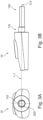
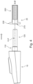
Figs. 2A and 2B are a front view and a detailed cutaway view of the sleeve, displaying the central horizontal axis (2-2') of the sleeve opening and the central horizontal axis (4-4') of the coupling portion. -
Figs. 3A and 3B are a front view and a detailed cutaway view of the adaptor, displaying the central horizontal axis (1-1') of the key element and the central horizontal axis (3-3') of the main body of the stem. -
Fig. 4 is a schematic side view of the adaptor and the sleeve before they are coupled, displaying the coincidence of the central horizontal axis of the sleeve opening and the central horizontal axis of the key element along a first horizontal axis A-A' and the coincidence between the central horizontal axis of the coupling portion and the central horizontal axis of the main body of the stem along a second horizontal axis B-B'. Moreover,fig. 4 displays that the second horizontal axis B-B' is off-centered relative to the first horizontal axis A-A'. -
Figs. 5A and 5B are schematic side views of the interconnecting mechanism before the rotating element is rotated in the engaged position. -
Figs. 6A and 6B are schematic side views of the interconnecting mechanism, after the rotating element has been rotated in the engaged position, displaying the principle of operation of the mechanism by tight-fitting / friction-fitting. -
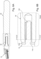
Fig. 7A is a front cutaway view of the interconnecting mechanism, along section Z-Z' offigs. 5A and 5B , of the interconnecting mechanism before the rotating element is rotated in the engaged position. -
Fig. 7B is a front cutaway view of the interconnecting mechanism, along section Z-Z' offigs. 6A and 6B , after the rotating element has been rotated in the engaged position, displaying the principle of operation of the mechanism by tight-fitting / friction-fitting. - Embodiments of the interconnecting mechanism will be described in reference to the drawings as follows.
-
Fig. 1 shows an exploded view of the interconnecting mechanism according to the present disclosure and of arazor handle 30. The interconnecting mechanism comprises a sleeve 20 extending between a distal end and a proximal end, wherein the proximal end of the sleeve 20 comprises a flange 230 and an opening 210, wherein the distal end of the sleeve 20 comprises a coupling portion 220, that is off-centered relative to a central horizontal axis 2-2' of the sleeve opening 210, wherein the sleeve 20 is configured to be coupled with a razor handle and an adaptor 10 comprising a stem having a main body 120, the adaptor 10 extending between a distal end and a proximal end, wherein the proximal end comprises a key element 110 configured to align the adaptor 10 with the sleeve opening 210 and wherein the distal end of the adaptor 10 comprises the main body of the stem 120 which is off-centered relative to a central horizontal axis 1-1' of the key element 110, wherein the central horizontal axis 2-2' of the sleeve opening 210 and the central horizontal axis 1-1' of the key element 110 are coincident along a first horizontal axis A-A' and wherein the main body of the stem 120 is configured to align with the coupling portion 220 of the sleeve along a second horizontal axis B-B' that is coincident with a central horizontal axis 3-3' of the main body of the stem 120 and with a central horizontal axis 4-4' of the coupling portion 220 and wherein the second horizontal axis B-B' is off-centered relative to the first horizontal axis A-A'. - It is imperative for the main body of the
stem 120 to be off-centered in relation to thekey element 110 since this is needed in order for thekey element 110 to be aligned with thesleeve opening 210 on a first horizontal axis A-A' and simultaneously for the main body of thestem 120 to be aligned with thecoupling portion 220 but on a different second horizontal axis B-B'. The fact that the first horizontal axis A-A' is off-centered in relation to second horizontal axis B-B' is what allows the rotatable element (being either theadaptor 10 or handle 30), when rotated towards an engagement direction, to lock theadaptor 10 with thesleeve 20 that is rotationally restricted relative to the razor handle 30, as will be explained in detail below. This ultimately leadsadaptor 10 to be locked with the razor handle 30. Moreover, it allows theadaptor 10 to be removed fromsleeve 20 and ultimately from razor handle 30, when rotating it opposite to the engagement direction. - Adaptors such as
adaptor 10 of the present disclosure are sometimes referred to as "modular" adaptors because they are constructed with standardized units or dimensions for flexibility and variety in use. As an example, in the present disclosure, such an adaptor can be used with a variety of different handles and/or sleeves. - In examples, the
key element 110 and the main body of thestem 120 may have a cylindrical shape. - In examples, the
adaptor 10 may be engaged with thesleeve 20 by interference, clearance or transition fitting, more specifically by snap-fitting or push-fitting. - In examples, the
adaptor 10 may be movably attached to thesleeve 20. - In examples, the
adaptor 10 may be removably attached to thesleeve 20. - In detail, the stem of the
adaptor 10 may be inserted into thesleeve 20 using the alignment provided by thekey element 110 and thesleeve opening 210, towards the direction of movement, as shown for example infig. 4 . As shown infig.4 , the central horizontal axis 1-1' of thekey element 110 and the central horizontal axis 2-2' of thesleeve opening 210, coincide along a first horizontal axis A-A', resulting in an alignment between the two elements. - In examples, the main body of the
stem 120 may also be engaged with thecoupling portion 220 as a result of the alignment between the central horizontal axis 3-3' of the main body of thestem 120 and the central horizontal axis 4-4' of thecoupling portion 220. As shown for example infig. 4 , the central horizontal axis 3-3' of the main body of thestem 120 and the central horizontal axis 4-4' of thecoupling portion 220, coincide along a second horizontal axis B-B', resulting in an alignment between the two elements. Moreover, as shown infig. 4 , the second horizontal axis B-B' is off-centered relative to the first horizontal axis A-A'. - In examples, a razor may be provided comprising the interconnecting mechanism and a
razor handle 30. - In examples, as shown in
fig.1 , the razor handle 30 may further comprise ahandle engaging portion 310, wherein thehandle engaging portion 310 may comprise an opening that is adapted to receive thesleeve 20 of the interconnecting mechanism. - In examples, as indicatively shown in
figs. 5A, 5B and7A , theadaptor 10 andsleeve 20 may then be inserted into the razorhandle engaging portion 310, located at the proximal end of the razor handle. Theflange 230 may be used as a stop element by coming in contact with the proximal end of the razor handle 30. Theflange 230 may be configured to stop thesleeve 20, preventing an undesired movement of thesleeve 20 all the way inside the razorhandle engaging portion 310. - In examples, the razor
handle engaging portion 310 may be configured for engaging thesleeve 20, more specifically locking the sleeve in place, thereby restricting the rotational movement of thesleeve 20 in relation to the razor handle 30. - In examples, the rotational movement may be restricted due to tight-fitting between the
sleeve 20 and the razorhandle engaging portion 310. - In examples, the rotation movement may be restricted due to friction-fitting between the
sleeve 20 and the razorhandle engaging portion 310. For example, thesleeve 20 may be made of rubber and the razorhandle engaging portion 310 may be made of rubber, plastic, paper, ceramic, wood, metal or glass. In that way, the friction between the material of therubber sleeve 20 and the material of the razorhandle engaging portion 310 may restrict the rotational movement between the two. - In examples, the proximal end of the
sleeve 20 may further comprise at least onelocking element 240 configured to be inserted in the razorhandle engaging portion 310. - In examples, the
handle engaging portion 310 may further comprise at least onegroove 340 that is designed such that the at least onelocking element 240 of thesleeve 20 is inserted in the at least onegroove 340. In another example, the at least onelocking element 240 may be a recess or groove and the at least onegroove 340 may be a bump or protrusion. - The at least one
locking element 240 may be configured to restrict the rotational movement of thesleeve 20 relative to the razor handle 30. For example, the at least onelocking element 240 may be configured to mate with the at least onegroove 340, located in the inner part of the razorhandle engaging portion 310. The mating may restrict the rotational movement between thesleeve 20 and the razor handle 30. - In examples, the
sleeve 20 and the razor handle 30 may be integrally formed, meaning they can be constructed as a unitary piece. Being a unitary piece, means that thesleeve 20 cannot rotate in relation to the razor handle 30. - In examples, as indicatively shown for example in
figs. 6A, 6B and7B , the main body of thestem 120 may be configured such that when the razor handle 30 or theadaptor 10 is rotated towards an engagement direction, the main body of thestem 120 is tight-fitted with thecoupling portion 220, thereby ensuring secure fastening of theadaptor 10 andsleeve 20 to the razor handle 30. In other examples, the main body of thestem 120 is friction-fitted with thecoupling portion 220. - In detail, when the
adaptor 10 is rotated towards an engagement direction, the main body of thestem 120 also rotates, being an integral part of theadaptor 10. As described above,sleeve 20 cannot rotate in relation to the razor handle 30. This causes the main body of thestem 120 to rotate within the now-immobile coupling portion 220 and creates a tight-fitting interference, locking theadaptor 10 together withsleeve 20 and razor handle 30. Thecoupling portion 220 is immobile, since it is a unitary part withsleeve 20 that is rotationally restricted in relation to the razor handle 30, due to tight-fitting, friction-fitting or because of the presence of at least onelocking element 240 and a corresponding at least one groove 34, as explained in detail above. The same principle applies when razor handle 30 is rotated towards an engagement direction, as shown for example infigs. 7A and 7B . The rotation of razor handle 30 also causessleeve 20 to rotate together with the razor handle 30, sincesleeve 20 cannot rotate in relation to razor handle 30, as described above. This causes thecoupling portion 220 to rotate in relation to the main body of the stem 120 (now being the immobile part) and creates a tight-fitting interference, locking theadaptor 10 together withsleeve 20 and razor handle 30. In other examples, the interference could be friction-fitting, also as described above.Figs. 7A and 7B show the cross-section along section Z-Z' that is shown infigs. 5B and6B . More specifically,fig. 7A shows the cross-section along section Z-Z' offig. 5B , prior to rotation of the rotating element andfig. 7B shows the cross-section Z-Z' offig. 6B , after the rotation of the rotating element towards an engagement direction. The rotation motion / direction is denoted infig. 7B by means of an arrow. - In examples, as indicatively shown for example in
figs. 5A, 5B and7A the main body of thestem 120 may configured such that when the razor handle 30 or theadaptor 10 is rotated to a direction that is opposite to the engagement direction, the connection between theadaptor 10 and the razor handle 30 becomes loose, thereby allowing to pull out theadaptor 10. - In that way, a full razor system (meaning the
adaptor 10, thesleeve 20 and the razor handle 30) may be disassembled and consequently facilitates the user to easily engage, disengage and exchange the various components of the razor system such as e.g., different razor handles, different adaptors etc. - In examples, the
coupling portion 220 may be comprise a uniform elastic body. - In examples, the
coupling portion 220 may be made of rubber or plastic. - In examples, the main body of the
stem 120 may be configured such that when the razor handle 30 or theadaptor 10 is rotated towards an engagement direction, the main body of thestem 120 may deform thecoupling portion 220. - In that way, due to the deformation of the
coupling portion 220, the main body of thestem 120 is snug-fitted with thecoupling portion 220, thereby ensuring secure fastening of theadaptor 10 andsleeve 20 to the razor handle 30. - In examples, when the razor handle 30 or
adaptor 10 is rotated towards an engagement direction, thecoupling portion 220 may deform outwardly. - In that way, due to the outwards extension of the
coupling portion 220, thesleeve 20 is securely fastened to the inside of the razorhandle receiving portion 310, thereby ensuring secure fastening of theadaptor 10 andsleeve 20 to the razor handle 30. - In examples, the main body of the
stem 120 may be configured such that when the razor handle 30 or theadaptor 20 is rotated opposite an engagement direction, thecoupling portion 220 may return to its initial shape, prior to deformation. This allows a full disassembling of the razor system as described above. It has to be understood that the initial shape of thecoupling portion 220 and consequently of thesleeve 20 corresponds to the shape before any deformation that is caused by the rotation of theadaptor 10 or of thehandle 30 as described in the current specification. - In examples, the
coupling portion 220 may comprise of a plurality of elastic projections. - In examples, when the razor handle 30 or
adaptor 10 is rotated towards an engagement direction, the plurality of elastic projections of thecoupling portion 220 may extend outwardly. In that way, due to the outwards extension of the elastic projections, thesleeve 20 is securely fastened to the inside of the razorhandle receiving portion 310, thereby ensuring secure fastening of theadaptor 10 andsleeve 20 to the razor handle 30. - In examples, the
coupling portion 220 may be configured such that when the razor handle 30 or theadaptor 10 is rotated opposite an engagement direction, the plurality of elastic projections of thecoupling portion 220 may return to their initial position, prior to their outward extension. It has to be understood that the initial position of the plurality of elastic projections of thecoupling portion 220 and consequently of thesleeve 20 corresponds to the position before any extension that is caused by the rotation of theadaptor 10 or of thehandle 30 as described in the current specification. This again allows a full disassembling of the razor system as described above. - Although only a number of particular embodiments and examples have been disclosed herein, it will be understood by those skilled in the art that other alternatives, obvious modifications and/or equivalents thereof are possible. Furthermore, the present disclosure aims to cover all possible combinations of the particular embodiments described. Reference signs related to drawings and placed in parentheses in a claim, are solely for attempting to increase the intelligibility of the claim and shall not be construed as limiting the scope of the claim. The scope of the present disclosure should not be limited by particular embodiments but should be determined only by a fair reading of the claims that follow.
Claims (15)
- An interconnecting mechanism for engaging an adaptor (10) to a razor handle (30) comprising:- a sleeve (20) extending between a distal end and a proximal end, wherein the proximal end of the sleeve (20) comprises a flange (230) and an opening (210), wherein the distal end of the sleeve (20) comprises a coupling portion (220), that is off-centered relative to a central horizontal axis (2-2') of the sleeve opening (210), wherein the sleeve (20) is configured to be coupled with a razor handle (30)- an adaptor (10) comprising a stem (120) having a main body, the adaptor (10) extending between a distal end and a proximal end, wherein the proximal end comprises a key element (110) configured to align the adaptor (10) with the sleeve opening (210) and wherein the distal end of the adaptor (10) comprises the main body of the stem (120) which is off-centered relative to a central horizontal axis (1-1') of the key element (110), wherein the central horizontal axis (2-2') of the sleeve opening (210) and the central horizontal axis (1-1') of the key element (110) are coincident along a first horizontal axis (A-A') and wherein the main body of the stem (120) is configured to align with the coupling portion (220) of the sleeve (20) along a second horizontal axis (B-B') that is coincident with a central horizontal axis (3-3') of the main body of the stem (120) and with a central horizontal axis (4-4') of the coupling portion (220) and wherein the second horizontal axis (B-B') is off-centered relative to the first horizontal axis (A-A').
- The mechanism of claim 1, wherein the key element (110) and the main body of the stem (120) have a cylindrical shape.
- The mechanism of claims 1-2, wherein the adaptor (10) is movably attached to the sleeve (20).
- The mechanism of any of the preceding claims, wherein the flange (230) is in contact with a proximal end of a razor handle (30).
- The mechanism of any of the preceding claims, wherein the stem (120) of the adaptor (10) is configured to be inserted into the sleeve opening (210).
- The mechanism of any of the preceding claims, wherein the proximal end of the sleeve (20) comprises at least one locking element (240).
- The mechanism of any of the preceding claims, wherein the coupling portion (220) of the sleeve (20) comprises a uniform elastic body.
- The mechanism of claims 1-6, wherein the coupling portion (220) of the sleeve (20) comprises of a plurality of elastic projections.
- A razor comprising the mechanism of claims 1-8 and a razor handle (30), the razor handle (30) comprising a handle engaging portion (310), wherein the handle engaging portion (310) comprises an opening that is adapted to receive the sleeve (20) of the interconnecting mechanism and wherein the main body of the stem (120) is configured such that when the adaptor (20) or the razor handle (30) is rotated towards an engagement direction, the main body of the stem (120) is tight-fitted with the coupling portion (220) of the sleeve (20).
- The razor of claim 9, wherein the proximal end of the sleeve (20) of the interconnecting mechanism comprises at least one locking element (240) and wherein the handle engaging portion (310) further comprises at least one groove (340) that is designed such that the at least one locking element (240) of the sleeve (20) is inserted in the at least one groove (340).
- The razor of claim 10, wherein the locking element (240) of the sleeve (20) is configured to restrict the rotational movement of the sleeve (20) relative to the razor handle (30).
- The razor of claims 9-11, wherein the sleeve (20) is fixedly attached to the razor handle (30).
- The razor of claims 9-12, wherein the main body of the stem (120) is configured such that when the razor handle (30) or the adaptor (10) is rotated towards an engagement direction, the main body of the stem (120) deforms the coupling portion (220) of the sleeve (20).
- The razor of claim 13, wherein when the razor handle (30) or the adaptor (10) is rotated towards an engagement direction, the coupling portion (220) of the sleeve (20) deforms outwardly.
- The razor of claim 9 comprising the interconnecting mechanism of claim 8, wherein the main body of the stem (120) is configured such that when the razor handle (30) or the adaptor (10) is rotated towards an engagement direction, the plurality of elastic projections of the coupling portion (220) of the sleeve (20) extend outwardly.
Priority Applications (3)
| Application Number | Priority Date | Filing Date | Title |
|---|---|---|---|
| EP23216371.7A EP4570459A1 (en) | 2023-12-13 | 2023-12-13 | Razor interconnecting mechanism |
| CN202480076529.3A CN122319062A (en) | 2023-12-13 | 2024-11-29 | Razor Interconnector |
| PCT/EP2024/084187 WO2025124938A1 (en) | 2023-12-13 | 2024-11-29 | Razor interconnecting mechanism |
Applications Claiming Priority (1)
| Application Number | Priority Date | Filing Date | Title |
|---|---|---|---|
| EP23216371.7A EP4570459A1 (en) | 2023-12-13 | 2023-12-13 | Razor interconnecting mechanism |
Publications (1)
| Publication Number | Publication Date |
|---|---|
| EP4570459A1 true EP4570459A1 (en) | 2025-06-18 |
Family
ID=89222630
Family Applications (1)
| Application Number | Title | Priority Date | Filing Date |
|---|---|---|---|
| EP23216371.7A Pending EP4570459A1 (en) | 2023-12-13 | 2023-12-13 | Razor interconnecting mechanism |
Country Status (3)
| Country | Link |
|---|---|
| EP (1) | EP4570459A1 (en) |
| CN (1) | CN122319062A (en) |
| WO (1) | WO2025124938A1 (en) |
Citations (3)
| Publication number | Priority date | Publication date | Assignee | Title |
|---|---|---|---|---|
| US10112313B2 (en) * | 2014-10-07 | 2018-10-30 | Ruairidh Robertson | Shaving device |
| EP3715071A1 (en) * | 2019-03-29 | 2020-09-30 | Bic Violex S.A. | Coupling, fabrication thereof, and handle and razor comprising same |
| EP3842196A1 (en) * | 2019-12-23 | 2021-06-30 | Bic Violex S.A. | Coupling mechanism |
-
2023
- 2023-12-13 EP EP23216371.7A patent/EP4570459A1/en active Pending
-
2024
- 2024-11-29 CN CN202480076529.3A patent/CN122319062A/en active Pending
- 2024-11-29 WO PCT/EP2024/084187 patent/WO2025124938A1/en active Pending
Patent Citations (3)
| Publication number | Priority date | Publication date | Assignee | Title |
|---|---|---|---|---|
| US10112313B2 (en) * | 2014-10-07 | 2018-10-30 | Ruairidh Robertson | Shaving device |
| EP3715071A1 (en) * | 2019-03-29 | 2020-09-30 | Bic Violex S.A. | Coupling, fabrication thereof, and handle and razor comprising same |
| EP3842196A1 (en) * | 2019-12-23 | 2021-06-30 | Bic Violex S.A. | Coupling mechanism |
Also Published As
| Publication number | Publication date |
|---|---|
| WO2025124938A1 (en) | 2025-06-19 |
| CN122319062A (en) | 2026-06-30 |
Similar Documents
| Publication | Publication Date | Title |
|---|---|---|
| US4148140A (en) | Folding hunting knife having ball latch | |
| EP0858383B1 (en) | Utility knife with blade magazine | |
| JP2633823B2 (en) | Universal knife | |
| US6591505B2 (en) | Folding knife with a locking catch | |
| CN111844140B (en) | Folding knife easy to detach | |
| US10828792B2 (en) | Lock-blade knife for cooking purposes | |
| US6282794B1 (en) | Rotary cutter with a blade cartridge | |
| TW202039188A (en) | Easily disassembled folding knife with replaceable blade | |
| US6745478B2 (en) | Multi-purpose work knife | |
| WO2017210043A1 (en) | Adapter for a handle and a cartridge of different razor systems | |
| EP3870413B1 (en) | Hand-held appliance with improved coupling structure for a functional attachment of the appliance | |
| EP3944935B1 (en) | Adapter for a razor system | |
| US2803877A (en) | Swivel knife | |
| US20210308889A1 (en) | Razor And Razor Handle With Rotational Portion | |
| EP2583800A1 (en) | Shaving razors | |
| US20220176576A1 (en) | Razor tool and method | |
| WO2025124938A1 (en) | Razor interconnecting mechanism | |
| CN113453855B (en) | Couplings, their manufacture and handles and razors containing the same | |
| CN106584526B (en) | a razor | |
| US5749115A (en) | Rotatable head hairbrush | |
| WO1999000224A2 (en) | Utility knife | |
| US5430940A (en) | Scissors combined with a cutter knife | |
| GB2209301A (en) | Hand tools | |
| CN115209772B (en) | Knife holder, jug combination and blender | |
| US6247234B1 (en) | Razor and blade |
Legal Events
| Date | Code | Title | Description |
|---|---|---|---|
| PUAI | Public reference made under article 153(3) epc to a published international application that has entered the european phase |
Free format text: ORIGINAL CODE: 0009012 |
|
| STAA | Information on the status of an ep patent application or granted ep patent |
Free format text: STATUS: THE APPLICATION HAS BEEN PUBLISHED |
|
| AK | Designated contracting states |
Kind code of ref document: A1 Designated state(s): AL AT BE BG CH CY CZ DE DK EE ES FI FR GB GR HR HU IE IS IT LI LT LU LV MC ME MK MT NL NO PL PT RO RS SE SI SK SM TR |
|
| STAA | Information on the status of an ep patent application or granted ep patent |
Free format text: STATUS: REQUEST FOR EXAMINATION WAS MADE |
|
| 17P | Request for examination filed |
Effective date: 20251127 |