EP4570408A1 - Gas-shielded arc welding method and method for welded-joint production - Google Patents
Gas-shielded arc welding method and method for welded-joint production Download PDFInfo
- Publication number
- EP4570408A1 EP4570408A1 EP23885378.2A EP23885378A EP4570408A1 EP 4570408 A1 EP4570408 A1 EP 4570408A1 EP 23885378 A EP23885378 A EP 23885378A EP 4570408 A1 EP4570408 A1 EP 4570408A1
- Authority
- EP
- European Patent Office
- Prior art keywords
- welding
- pulse
- less
- gas
- peak current
- Prior art date
- Legal status (The legal status is an assumption and is not a legal conclusion. Google has not performed a legal analysis and makes no representation as to the accuracy of the status listed.)
- Pending
Links
Images



Classifications
-
- B—PERFORMING OPERATIONS; TRANSPORTING
- B23—MACHINE TOOLS; METAL-WORKING NOT OTHERWISE PROVIDED FOR
- B23K—SOLDERING OR UNSOLDERING; WELDING; CLADDING OR PLATING BY SOLDERING OR WELDING; CUTTING BY APPLYING HEAT LOCALLY, e.g. FLAME CUTTING; WORKING BY LASER BEAM
- B23K9/00—Arc welding or cutting
- B23K9/095—Monitoring or automatic control of welding parameters
-
- B—PERFORMING OPERATIONS; TRANSPORTING
- B23—MACHINE TOOLS; METAL-WORKING NOT OTHERWISE PROVIDED FOR
- B23K—SOLDERING OR UNSOLDERING; WELDING; CLADDING OR PLATING BY SOLDERING OR WELDING; CUTTING BY APPLYING HEAT LOCALLY, e.g. FLAME CUTTING; WORKING BY LASER BEAM
- B23K9/00—Arc welding or cutting
- B23K9/06—Arrangements or circuits for starting the arc, e.g. by generating ignition voltage, or for stabilising the arc
- B23K9/073—Stabilising the arc
-
- B—PERFORMING OPERATIONS; TRANSPORTING
- B23—MACHINE TOOLS; METAL-WORKING NOT OTHERWISE PROVIDED FOR
- B23K—SOLDERING OR UNSOLDERING; WELDING; CLADDING OR PLATING BY SOLDERING OR WELDING; CUTTING BY APPLYING HEAT LOCALLY, e.g. FLAME CUTTING; WORKING BY LASER BEAM
- B23K9/00—Arc welding or cutting
- B23K9/09—Arrangements or circuits for arc welding with pulsed current or voltage
-
- B—PERFORMING OPERATIONS; TRANSPORTING
- B23—MACHINE TOOLS; METAL-WORKING NOT OTHERWISE PROVIDED FOR
- B23K—SOLDERING OR UNSOLDERING; WELDING; CLADDING OR PLATING BY SOLDERING OR WELDING; CUTTING BY APPLYING HEAT LOCALLY, e.g. FLAME CUTTING; WORKING BY LASER BEAM
- B23K9/00—Arc welding or cutting
- B23K9/16—Arc welding or cutting making use of shielding gas
-
- B—PERFORMING OPERATIONS; TRANSPORTING
- B23—MACHINE TOOLS; METAL-WORKING NOT OTHERWISE PROVIDED FOR
- B23K—SOLDERING OR UNSOLDERING; WELDING; CLADDING OR PLATING BY SOLDERING OR WELDING; CUTTING BY APPLYING HEAT LOCALLY, e.g. FLAME CUTTING; WORKING BY LASER BEAM
- B23K9/00—Arc welding or cutting
- B23K9/16—Arc welding or cutting making use of shielding gas
- B23K9/173—Arc welding or cutting making use of shielding gas and of a consumable electrode
-
- B—PERFORMING OPERATIONS; TRANSPORTING
- B23—MACHINE TOOLS; METAL-WORKING NOT OTHERWISE PROVIDED FOR
- B23K—SOLDERING OR UNSOLDERING; WELDING; CLADDING OR PLATING BY SOLDERING OR WELDING; CUTTING BY APPLYING HEAT LOCALLY, e.g. FLAME CUTTING; WORKING BY LASER BEAM
- B23K2103/00—Materials to be soldered, welded or cut
- B23K2103/02—Iron or ferrous alloys
- B23K2103/04—Steel or steel alloys
Definitions
- the present invention relates to a gas-shielded arc welding method for producing a stable welded joint form while suppressing slag formation, and to a method for manufacturing a welded joint.
- Electrodeposition coating is preceded by a pretreatment for improving the adhesion between a base steel sheet including a weld metal, and an electrodeposition coating film.
- electrodeposition coating is performed after a chemical conversion treatment (such as, for example, zinc phosphate treatment) is applied to the base steel sheet and the weld metal.
- the zinc phosphate treatment which is a common example of the chemical conversion treatments, is a technique in which zinc phosphate crystals are grown on the surface of a base steel sheet and a weld metal to increase the adhesion of a coating film formed by electrodeposition coating.
- a chemical conversion treatment such as, for example, zinc phosphate treatment
- Patent Literature 1 discloses a technique in which an arc weld and the vicinity thereof, before being electrodeposition coated, are sprayed with or immersed in a non-oxidizing acidic solution with a pH of 2 or less at a liquid temperature of 30 to 90°C. This technique removes slag (a), welding fumes (b), and oxides (c) by dissolving the weld bead and the steel sheet with the non-oxidizing solution.
- Patent Literature 1 requires rinsing of the acidic solution before electrodeposition coating, and this fact makes the member manufacturing process complicated.
- a member fabricated into a desired shape is a result of overlapping and joining of steel sheets having various shapes and can trap a residue of the acidic solution in gaps between the overlapped steel sheets, thus undergoing severe corrosion.
- the technique involves a large amount of the acidic solution and thus the manufacturing equipment is exposed to a corrosive environment and is easily corroded or broken down.
- the scattering of fumes needs to be prevented in order to ensure the safety of workers.
- Patent Literature 2 discloses a technique that increases the post-coating corrosion resistance of a weld and the vicinity thereof by reducing the total amount of Si in a welding wire used in arc welding and a base material, and also by increasing the total amount of Mn in the welding wire and the base material.
- Patent Literature 2 needs to use thick steel sheets in order to ensure the strength of members and will not succeed in achieving weight reduction of car body and structures.
- Patent Literature 3 discloses a technique that allows a chemical conversion layer to be formed sufficiently even on a weld bead that bears slag, welding fumes, and oxides, by controlling the composition of a treatment liquid used in the chemical conversion treatment. Specifically, the formation of a chemical conversion layer is facilitated by surface-treating the steel with a surface-conditioning liquid containing colloidal zinc phosphate. Furthermore, the steel is chemically converted with a zinc phosphate treatment liquid having a F content of 100 mass ppm or more. This treatment dissolves and removes slag, welding fumes, and oxides and thereby increases the adhesion of a coating film that will be formed by electrodeposition coating.
- the zinc phosphate treatment liquid used in the technique disclosed in Patent Literature 3 contains fluorine that is designated as a toxic substance, and the fluorine content must be lowered to a level meeting environmental standards when the liquid waste is discharged outside the factory.
- a large-scale liquid waste disposal facility is necessary in addition to the member manufacturing facility.
- the present invention has been made in view of the problems discussed above. It is therefore an object of the present invention to provide a gas-shielded arc welding method and a method for manufacturing a welded joint that can prevent the intrusion of oxygen into a weld metal without using a special device and can suppress the formation of slag, and that can stably produce welded joints with a good bead shape.
- the present inventors have found that the most effective way to enhance the corrosion resistance of welds and to stably obtain welded joints with a good bead shape is to reduce the amount of slag that is attached to the welds and to realize periodic short-circuit transfer using pulse welding.
- the present inventors have found that the quotient of the difference between the pulse peak current (Ip) and the pulse base current (Ib) in a pulse current waveform divided by the base material to contact tip distance (L) is a factor that is highly related to facilitating the occurrence of short-circuiting, and the factor should satisfy a specific relational expression with the welding speed (V) and thereby enables stable production of welded joints having a good bead shape.
- the technique of the present invention is based on the finding that the quotient of the difference between the pulse peak current (Ip) and the pulse base current (Ib) divided by the base material to contact tip distance (L) is a factor that serves as an index of the ease of short-circuiting, and welded joints having a good bead shape can be obtained stably when this factor satisfies a specific relational expression with the welding speed (V) that varies depending on the welding speed.
- a gist of the present invention is as follows.
- welded joints with a good bead shape can be obtained stably under a wide range of welding speed conditions. Moreover, the intrusion of oxygen into the weld metal and the formation of slag can be suppressed without making special changes to the conventional welding device used in carbon dioxide gas welding, MAG welding with an inert gas-active gas mixture, or MIG welding with an inert gas-based gas.
- Fig. 1 is a schematic view illustrating an exemplary welded joint produced by arc welding according to an embodiment of the present invention. While the figure illustrates fillet welding of a lap joint as a typical example, the welded joint form and the welding attitude in the present invention are not limited.
- a welding wire 1 is continuously fed from a welding torch 2 to a base material 3 (specifically, a weld seam defined by the corner of a step formed by lapping of, for example, two sheets of the base material 3) through a central portion of the welding torch 2.
- the welding wire 1 is used as the anode, and the base material 3 is used as the cathode.
- a welding voltage is applied from a welding power supply (not shown).
- a contact tip 11 is attached inside the welding torch 2. The contact tip 11 serves to supply power to the welding wire 1 and guide the wire feed.
- Part of an Ar shielding gas (not shown) supplied from the inside of the welding torch 2 is ionized into plasma, thereby forming an arc 5 between the welding wire 1 and the base material 3.
- Part of the Ar shielding gas that is not ionized and flows from the welding torch 2 to the base material 3 plays a role of shielding the arc 5 and a molten pool (not shown in Fig. 1 ) formed by melting of the base material 3 from the outside air.
- the heat input from the arc 5 melts the tip of the welding wire 1 to form a droplet, and the droplet is transported to the molten pool by, for example, electromagnetic force or gravity. This phenomenon occurs continuously while the welding torch 2 or the base material 3 is moved.
- the molten pool behind the process along the weld seam solidifies to form a weld bead 6. In this manner, at least two steel sheets are joined together.
- MAG welding or MIG welding is a reversed polarity welding in which an electrode (a wire) is the anode.
- cathode spots are formed from regions, such as oxides, that have a low work function and easily emit electrons.
- an aluminum alloy having a strong oxide film on the surface of the base material can be favorably welded because cathode spots are formed stably from the oxide film on the weld seam.
- steel rarely has an oxide film and therefore cathode spots are not fixed in MIG welding that does not generate oxides derived from O 2 or CO 2 .
- the cathode spots move around on the surface of the base material vigorously in search of places where the work function is low.
- the welding is destabilized and the welded joint that is obtained has a meandering or wavy weld bead 6.
- Fig. 2(a) and Fig. 2(b) are schematic views illustrating droplet transfer in conventional MIG welding.
- Such unstable droplet transfer will be effectively avoided by causing droplets 7 to be detached regularly from the tip of the welding wire 1.
- the present invention is based on the finding that droplet transfer is effectively stabilized by completing the joining by so-called periodic short-circuit transfer in which the non-short-circuited state of Fig. 3(a) and the short-circuited state of Fig. 3(b) are regularly repeated between the tip of the welding wire 1 and the base material 3, and a droplet 7 is allowed to be transferred to the base material 3 during the short-circuited state.
- the present inventors carried out further welding experiments and have found that the quotient of the difference between the pulse peak current (Ip) and the pulse base current (Ib) divided by the distance (L) between the contact tip and the base material 3 ((Ip - Ib)/L) is a factor that determines the ease of short-circuit transfer.
- the present inventors have found that (Ip - Ib)/L is preferably controlled to the range of 20 to 43, and the meandering of the weld bead 6 can be suppressed when this factor satisfies a specific relationship that varies depending on the welding speed.
- the amount of slag attached to the weld needs to be reduced in order to enhance the corrosion resistance of the weld.
- the shielding gas that is used needs to be a gas containing 98 vol% or more Ar.
- Argon is preferably contained 99 vol% or more.
- the upper limit is not limited, and argon may represent 100 vol%.
- the pulse peak current (Ip) is 300 A or more and 600 A or less.
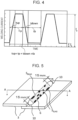
- Fig. 4 illustrates a schematic diagram of a pulse current waveform in the arc welding of the present invention.
- Pulse welding is a method of welding in which a pulse peak current (Ip) and a pulse base current (Ib) are periodically repeated. If the pulse peak current (Ip) is excessively low, an action that pushes down the droplet 7 formed at the tip of the welding wire 1 to the molten pool 8 cannot be obtained and short-circuiting may become unstable. Furthermore, sufficient heat input cannot be ensured and the bead shape may be deteriorated. Thus, the pulse peak current (Ip) is limited to 300 A or more.
- the pulse peak current (Ip) is preferably 350 A or more, more preferably 380 A or more, and still more preferably 400 A or more.
- the pulse peak current (Ip) is limited to 600 A or less.
- the pulse peak current (Ip) is preferably 590 A or less, more preferably 580 A or less, and still more preferably 570 A or less.
- the pulse peak current time (tp) per cycle is preferably 0.5 ms or more.
- the pulse peak current time (tp) per cycle is more preferably 0.7 ms or more, and still more preferably 0.8 ms or more.
- the pulse peak current time (tp) per cycle is desirably 3.5 ms or less.
- the pulse peak current time (tp) per cycle is more preferably 3.3 ms or less, and still more preferably 3.2 ms or less.
- the pulse base current (Ib) is 30 A or more and 120 A or less (preferred condition).
- the pulse base current (Ib) is preferably 30 A or more.
- the pulse base current (Ib) is more preferably 35 A or more, still more preferably 40 A or more, and most preferably 45 A or more.
- the pulse base current (Ib) is preferably 120 A or less.
- the pulse base current (Ib) is more preferably 110 A or less, still more preferably 100 A or less, and most preferably 90 A or less.
- the pulse base current time (tb) per cycle (per pulse cycle) is preferably 1.0 ms or more.
- the pulse base current time (tb) per cycle (per pulse cycle) is more preferably 1.5 ms or more, and still more preferably 2.0 ms or more. If the pulse base current time (tb) is too long, short-circuiting may not be controlled as intended in the pulse peak period, or the arc 5 and the molten pool 8 may be significantly disturbed during short-circuiting.
- the pulse base current time (tb) per cycle is preferably 10.0 ms or less.
- the pulse base current time (tb) per cycle is more preferably 9.0 ms or less, and still more preferably 8.0 ms or less.
- the rise-up time (tup) is preferably 0.1 ms or more, more preferably 0.3 ms or more, and still more preferably 0.5 ms or more.
- the rise-up time (tup) is preferably 3.0 ms or less, more preferably 2.8 ms or less, and still more preferably 2.5 ms or less.
- the fall-down time (tdown) is preferably 0.1 ms or more, more preferably 0.3 ms or more, and still more preferably 0.5 ms or more.
- the fall-down time (tdown) is preferably 3.0 ms or less, more preferably 2.8 ms or less, and still more preferably 2.5 ms or less.
- the welding speed (V) is 80 cm/min or more and 200 cm/min or less.
- An increase in welding speed (V) lowers the stability of the arc 5 and makes it difficult to control periodic short-circuit transfer.
- the above phenomenon is particularly noticeable under welding conditions where the welding speed is 80 cm/min or more, and thus the welding speed needs to be limited to the range described below.
- welding under conditions where the welding speed (V) is more than 200 cm/min encounters difficulties in achieving a desired weld bead shape and a desired penetration shape, or such welding is accompanied by disturbance of the arc 5 that causes air entrainment and may result in slag formation.
- the welding speed (V) of interest in the present invention is 80 cm/min or more and 200 cm/min or less.
- the factor (Ip - Ib)/L which is the quotient of the difference between the pulse peak current (Ip) and the pulse base current (Ib) divided by the distance (L) between the base material 3 and the contact tip 11, is not particularly limited.
- This factor found in the present invention is an index of the ease of short-circuit transfer and is an important feature of the present invention. If (Ip - Ib)/L is excessively small, short-circuit transfer is unlikely to occur or, even if short-circuit transfer occurs, will be unstable and give a faulty bead shape.
- (Ip - Ib)/L is preferably controlled to 20 A/mm or more, and is more preferably 22 A/ms or more, and still more preferably 25 A/ms or more.
- (Ip - Ib)/L is preferably controlled to 43 A/mm or less, and is more preferably 41 A/ms or less, and still more preferably 40 A/ms or less.
- the pulse peak current (Ip), the pulse base current (Ib), the base material to contact tip distance (L), and the welding speed (V) satisfy expressions (1) and (2) below: 0.15V - 3 ⁇ (Ip - Ib)/L ⁇ 0.1V + 38 (when the welding speed V is 80 cm/min or more and less than 120 cm/min) 0.18V - 5 ⁇ (Ip - Ib)/L ⁇ 0.12V + 35 (when the welding speed V is 120 cm/min or more and 200 cm/min or less)
- Ip (A) is the pulse peak current
- Ib (A) is the pulse base current
- L (mm) is the base material to contact tip distance
- V (cm/min) is the welding speed.
- the difference between the pulse peak current (Ip) and the pulse base current (Ib), and the distance (L) between the base material 3 and the contact tip 11 need to be in the ranges satisfying expressions (1) and (2).
- the welding speed V is 80 cm/min or more and less than 120 cm/min, a failure for (Ip - Ib)/L to be equal to or greater than 0.15V - 3 makes it difficult to realize short-circuit transfer that is free from the influence of the fluctuation of the arc 5.
- this ratio needs to be equal to or greater than 0.15V - 3, and is preferably equal to or greater than 0.15V - 2, and more preferably equal to or greater than 0.15V - 1. If, on the other hand, the ratio is more than 0.1V + 38, the arc 5 and the molten pool 8 are much disturbed during short-circuiting and the weld bead shape may be defective. Thus, the ratio needs to be equal to or less than 0.1V + 38, and is preferably equal to or less than 0.1V + 36, and more preferably equal to or less than 0.1V + 34.
- this ratio needs to be equal to or greater than 0.18V - 5, and is preferably equal to or greater than 0.18V - 4, and more preferably equal to or greater than 0.18V - 3. If, on the other hand, the ratio is more than 0.12V + 35, the arc 5 and the molten pool 8 are much disturbed during short-circuiting and the weld bead shape may be defective. Thus, the ratio needs to be equal to or less than 0.12V + 35, and is preferably equal to or less than 0.12V + 33, and more preferably equal to or less than 0.12V + 31.
- the arc 5 is more prone to destabilization when the welding speed V is 120 cm/min or more and 200 cm/min or less. Under such high-speed conditions, it is effective to increase the slope of (Ip - Ib)/L relative to V compared to when the welding speed is 80 cm/min or more and less than 120 cm/min.
- the average frequency of short-circuit transfers (the short-circuit frequency) F (Hz) that affects the volume of the droplet 7 at the tip of the wire is not particularly limited but is preferably 20 Hz or more, more preferably 30 Hz or more, and still more preferably 40 Hz or more.
- the upper limit is preferably 200 Hz or less, more preferably 180 Hz or less, and still more preferably 150 Hz or less.
- the average frequency of short-circuit transfers (the short-circuit frequency) F (Hz) can be measured by monitoring the arc voltage during welding with an oscilloscope to count the number of times the arc voltage becomes zero, and dividing the count by the monitoring time to calculate the number of counts per second. If the monitoring time is too short, the difference in count will be large.
- the monitoring time is preferably 0.5 s or more, more preferably 0.8 s or more, and still more preferably 1.0 s or more.
- the upper limit is not particularly limited but is preferably 3.0 s or less because the count processing time is extended with increasing volume of measurement data and thus workability is lowered.
- the reasons for the above is that when the short-circuit frequency is measured in-process and the welding conditions are feedback controlled, an excessively long monitoring time makes it difficult to perform instantaneous feedback control depending on the welding situation.
- the welding current is 150 A to 300 A
- the arc voltage is 20 V to 35 V
- the distance between the base material 3 and the contact tip 11 is 5 mm to 30 mm
- the Ar shielding gas flow rate is 10 L/min to 25 L/min.
- the welding current is preferably 150 A or more, more preferably 170 A or more, and still more preferably 180 A or more.
- the welding current is preferably 300 A or less, more preferably 280 A or less, and still more preferably 270 A or less.
- the arc voltage is preferably 20 V or more, more preferably 21 V or more, and still more preferably 22 V or more.
- the arc voltage is preferably 35 V or less, more preferably 32 V or less, and still more preferably 30 V or less.
- the distance between the base material 3 and the contact tip 11 is preferably 5 mm or more, more preferably 8 mm or more, and still more preferably 10 mm or more.
- the distance between the base material 3 and the contact tip 11 is preferably 30 mm or less, more preferably 25 mm or less, and still more preferably 20 mm or less.
- the Ar shielding gas flow rate is preferably 10 L/min or more, more preferably 12 L/min or more, and still more preferably 15 L/min or more.
- the Ar shielding gas flow rate is preferably 25 L/min or less, more preferably 24 L/min or less, and still more preferably 22 L/min or less.
- the welding current and the arc voltage are the averages in each welding pass. More specifically, the welding current is the average of the pulse peak current and the pulse base current. Control of this makes it possible to grasp the total heat input during welding.
- the welding wire 1 used in the present invention is not particularly limited.
- solid wires such as YGW12 and YGW16 described in JIS Z 3312, may be used.
- the base materials 3 of interest in the present invention are steel sheets and coated steel sheets.
- the chemical composition of the steel sheets is not limited.
- the steel sheets preferably contain C: 0.02 mass% to 0.3 mass%, Si: 0.01 mass% or more, Mn: 0.5% mass% or more, P: 0.05 mass% or less, and S: 0.05 mass% or less, and may further contain alloying elements, such as Cu, Ni, Cr, and Ti.
- the Si content is preferably 3.0 mass% or less
- the Mn content is preferably 5.0 mass% or less.
- the lower limit of P is not particularly limited, but is preferably 0.0005 mass% or more.
- the lower limit of S is not particularly limited, but is preferably 0.0005 mass% or more.
- the coating composition in the coated steel sheets is not particularly limited.
- the coating may be Zn.
- the above limitations enable the manufacturing of a welded joint with a good bead shape while suppressing the formation of slag in the weld, making it possible to obtain such a welded joint.
- the amount of slag formation was evaluated by the method described in Examples.
- a new technical idea of the present invention resides in the finding that the quotient of the difference between the pulse peak current (Ip) and the pulse base current (Ib) divided by the distance (L) between the base material 3 and the contact tip 11 is a factor that determines the ease of short-circuiting in the control of bead shape, and combining this index with the welding speed is a very effective tool for controlling the bead shape.
- the present invention is also advantageously characterized by its high robustness.
- High robustness means that the inventive technique is less susceptible to disturbances, such as environment and sheet shape, and has a wide range of appropriate welding conditions.
- Two steel sheets (both 2.6 mm thick) having a chemical composition described in Table 1 were lapped and were fillet welded by an exemplary method illustrated in Fig. 1 .
- the steel sheets contained Fe and alloying elements, such as Cu, Ni, Cr, and Ti.
- the welding was performed under the welding conditions described in Table 2.
- YGW16 specified in JIS Z 3312 was used as the welding wire 1.
- the welded steel sheets obtained as described above were tested by the following methods to evaluate the slab-covered area ratio and the bead width ratio.
- Fig. 5 is a schematic view illustrating the bead area and the slag-covered area of a weld bead.
- the surface of the weld bead 6 excluding the bead-start and bead-finish end portions 10 (each 15 mm long) is photographed from directly above, and the projected areas from above of the weld bead 6 and the slag are measured to calculate the bead surface area S BEAD and the slag-covered surface area S SLAG illustrated in Fig. 5 .
- the length of the weld bead 6 is less than 130 mm, the surface over the entire length excluding the bead-start and bead-finish end portions 10 is photographed.
- the surface of a randomly selected region (100 mm in length) excluding the bead-start and bead-finish end portions 10 is photographed.
- the value of the slag surface area S SLAG was divided by the value of the bead surface area S BEAD to give the slag-covered area ratio S RATIO .
- S RATIO of 30% or less was acceptable.
- Fig. 6 is a schematic view illustrating the minimum value and the maximum value of bead width.
- the maximum value W MAX and the minimum value W MIN of the width of a bead similar to that illustrated in Fig. 6 were determined as follows.
- the surface of the weld bead 6 excluding the bead-start and bead-finish end portions 10 (each 15 mm long) was photographed, and the photograph was analyzed.
- the length of the weld bead 6 was less than 130 mm, the surface over the entire length excluding the bead-start and bead-finish end portions 10 was photographed.
- the welding conditions Nos. 1 to 5 achieved 80% or more W RATIO , and afforded a more stable welded joint form.
Landscapes
- Engineering & Computer Science (AREA)
- Physics & Mathematics (AREA)
- Plasma & Fusion (AREA)
- Mechanical Engineering (AREA)
- Arc Welding In General (AREA)
- Arc Welding Control (AREA)
Abstract
Description
- The present invention relates to a gas-shielded arc welding method for producing a stable welded joint form while suppressing slag formation, and to a method for manufacturing a welded joint.
- In recent years, there has been a growing need for automobiles to use stronger and more rigid members in car body and structures in order to enhance the safety and reliability of the car body and structures and at the same time to use lightweight members in order to improve fuel efficiency. As a result, efforts are being made to reduce the thickness of steel sheets for such members by the use of high-strength steel sheets. Among the various members used in automobiles, in particular, suspension members (such as, for example, lower arms) are made of thick steel sheets compared to bodies from the points of view of the strength and rigidity of the members. Thus, further reduction in the weight of car body and structures will be achieved if the thickness of steel sheets used in suspension members can be further reduced by increasing the strength of the steel sheets. This will realize improved fuel efficiency while ensuring the strength and rigidity of members.
- In general, members that will be used in corrosive environments are subjected to antirust treatments, such as chemical conversion treatment and electrodeposition coating, after being welded in order to ensure corrosion resistance. Unfortunately, it is often the case that the welds and the vicinities thereof are rusted or corroded over time. The corrosion that occurs in the electrodeposition-coated member tends to start at the weld. Over time, the corrosion spreads widely on the weld and its surroundings while causing blisters on the coating film, and also progresses in the thickness direction. The progress of corrosion reduces the thickness at the weld and the vicinity thereof, and consequently lowers the strength of the weld and ultimately weakens the strength of the member. That is, the occurrence and progress of corrosion in a member where a load acts on a weld (such as, for example, automobile suspension members) can lead to the destruction of the member.
- Electrodeposition coating is preceded by a pretreatment for improving the adhesion between a base steel sheet including a weld metal, and an electrodeposition coating film. Specifically, electrodeposition coating is performed after a chemical conversion treatment (such as, for example, zinc phosphate treatment) is applied to the base steel sheet and the weld metal. The zinc phosphate treatment, which is a common example of the chemical conversion treatments, is a technique in which zinc phosphate crystals are grown on the surface of a base steel sheet and a weld metal to increase the adhesion of a coating film formed by electrodeposition coating. Unfortunately, even members that have been chemically converted by the conventional technique prior to electrodeposition coating frequently develop blisters on the coating film with time over a wide area on the weld and its surroundings. That is, it is difficult for the conventional chemical conversion pretreatment followed by electrodeposition coating to completely suppress the occurrence of corrosion from the weld.
- When members made of steel sheets with coating layer are arc welded, the welds are subjected to high temperature by the arc plasma (hereinafter, "arc") that is the heat source, and the coating layers are vaporized to expose uncoated portions locally. As a result, a significant enhancement in corrosion resistance that will justify the use of expensive precoated steel sheets cannot be expected.
- As described above, various manufacturing techniques have been developed so as to improve the corrosion resistance of members, but each has its own advantages and disadvantages. To enhance corrosion resistance while avoiding the increase in manufacturing costs, techniques have been studied that can prevent more effectively the occurrence and progress of corrosion from a weld.
- It is conventionally known that corrosion of a weld starts from:
- (a) slag attached to the weld (mainly the surface of the weld bead),
- (b) welding fumes attached to the weld, and
- (c) oxides formed on the surface of the steel sheets exposed to high temperatures by welding. In the presence of the deposits (a) and/or (b) or of the oxides (c) on the weld, chemical conversion treatment locally fails to coat the member with a chemical conversion layer of zinc phosphate crystals, and the deposits and/or the products remain on exposed regions. Such regions do not allow an electrodeposition coating film to be formed sufficiently, and the adhesion of the coating film is insufficient to cause a significant decrease in corrosion resistance. As a result, corrosion occurs and progresses and the sheet loses thickness. The techniques described below address the prevention of the occurrence of deposits (a) and (b) and of oxides (c) mentioned above.
- For example,
Patent Literature 1 discloses a technique in which an arc weld and the vicinity thereof, before being electrodeposition coated, are sprayed with or immersed in a non-oxidizing acidic solution with a pH of 2 or less at a liquid temperature of 30 to 90°C. This technique removes slag (a), welding fumes (b), and oxides (c) by dissolving the weld bead and the steel sheet with the non-oxidizing solution. - However, the technique disclosed in
Patent Literature 1 requires rinsing of the acidic solution before electrodeposition coating, and this fact makes the member manufacturing process complicated. In addition, a member fabricated into a desired shape is a result of overlapping and joining of steel sheets having various shapes and can trap a residue of the acidic solution in gaps between the overlapped steel sheets, thus undergoing severe corrosion. Furthermore, the technique involves a large amount of the acidic solution and thus the manufacturing equipment is exposed to a corrosive environment and is easily corroded or broken down. In addition, the scattering of fumes needs to be prevented in order to ensure the safety of workers. -
Patent Literature 2 discloses a technique that increases the post-coating corrosion resistance of a weld and the vicinity thereof by reducing the total amount of Si in a welding wire used in arc welding and a base material, and also by increasing the total amount of Mn in the welding wire and the base material. - However, reducing the Si content in order to suppress slag formation inevitably lowers the strength of the steel sheet. That is, the technique disclosed in
Patent Literature 2 needs to use thick steel sheets in order to ensure the strength of members and will not succeed in achieving weight reduction of car body and structures. -
Patent Literature 3 discloses a technique that allows a chemical conversion layer to be formed sufficiently even on a weld bead that bears slag, welding fumes, and oxides, by controlling the composition of a treatment liquid used in the chemical conversion treatment. Specifically, the formation of a chemical conversion layer is facilitated by surface-treating the steel with a surface-conditioning liquid containing colloidal zinc phosphate. Furthermore, the steel is chemically converted with a zinc phosphate treatment liquid having a F content of 100 mass ppm or more. This treatment dissolves and removes slag, welding fumes, and oxides and thereby increases the adhesion of a coating film that will be formed by electrodeposition coating. - However, the zinc phosphate treatment liquid used in the technique disclosed in
Patent Literature 3 contains fluorine that is designated as a toxic substance, and the fluorine content must be lowered to a level meeting environmental standards when the liquid waste is discharged outside the factory. Thus, a large-scale liquid waste disposal facility is necessary in addition to the member manufacturing facility. -
- PTL 1:
Japanese Unexamined Patent Application Publication No. 9-20994 - PTL 2:
Japanese Unexamined Patent Application Publication No. 8-33997 - PTL 3:
Japanese Patent No. 5549615 - The present invention has been made in view of the problems discussed above. It is therefore an object of the present invention to provide a gas-shielded arc welding method and a method for manufacturing a welded joint that can prevent the intrusion of oxygen into a weld metal without using a special device and can suppress the formation of slag, and that can stably produce welded joints with a good bead shape.
- The present inventors have found that the most effective way to enhance the corrosion resistance of welds and to stably obtain welded joints with a good bead shape is to reduce the amount of slag that is attached to the welds and to realize periodic short-circuit transfer using pulse welding.
- In order to reduce the amount of slag formed in a weld, it is important to suppress the oxidation of Si, Mn, Ti, etc. contained in the steel sheets and the welding wire. The oxidation of these elements is suppressed and the amount of slag formation can be reduced by the use of a shielding gas containing a reduced amount of an oxidizing gas. When, however, gas-shielded arc welding is performed at a welding speed of 80 to 200 cm/min in a shielding gas containing a high proportion of Ar gas, the cathode spot crawls around on the steel sheet surface after the oxide film on the steel sheet surface has been removed by the cleaning action, thus making the arc unstable. As a result, another problem occurs in which oxygen stemming from air entrainment is mixed into the molten pool or the weld bead shape is deteriorated. The present inventors have worked on these new problems and have conceived that pulse welding will reduce the crawling of the cathode spot and will realize periodic short-circuit transfer that is less susceptible to arc fluctuations. Furthermore, the present inventors have found that the quotient of the difference between the pulse peak current (Ip) and the pulse base current (Ib) in a pulse current waveform divided by the base material to contact tip distance (L) is a factor that is highly related to facilitating the occurrence of short-circuiting, and the factor should satisfy a specific relational expression with the welding speed (V) and thereby enables stable production of welded joints having a good bead shape. That is, the technique of the present invention is based on the finding that the quotient of the difference between the pulse peak current (Ip) and the pulse base current (Ib) divided by the base material to contact tip distance (L) is a factor that serves as an index of the ease of short-circuiting, and welded joints having a good bead shape can be obtained stably when this factor satisfies a specific relational expression with the welding speed (V) that varies depending on the welding speed.
- The present invention is completed based on the above findings. A gist of the present invention is as follows.
- [1] A gas-shielded arc welding method of forming a joint by short-circuiting a base material and a welding wire supplied with power from a contact tip in a welding torch, wherein the gas-shielded arc welding method performs pulse welding in which a pulse peak current (Ip) and a pulse base current (Ib) are periodically repeated, and the pulse peak current (Ip) in the pulse welding is 300 A or more and 600 A or less,
- a welding speed (V) is 80 cm/min or more and 200 cm/min or less,
- when the welding speed (V) is 80 cm/min or more and less than 120 cm/min, the pulse peak current (Ip), the pulse base current (Ib), a base material to contact tip distance (L), and the welding speed (V) satisfy expression (1) below,
- when the welding speed (V) is 120 cm/min or more and 200 cm/min or less, the pulse peak current (Ip), the pulse base current (Ib), a base material to contact tip distance (L), and the welding speed (V) satisfy expression (2) below, and a gas containing 98 vol% or more Ar is used as a shielding gas,


- wherein in expressions (1) and (2), Ip (A) is the pulse peak current, Ib (A) is the pulse base current, L (mm) is the base material to contact tip distance, and V (cm/min) is the welding speed.
- [2] The gas-shielded arc welding method according to [1], wherein the pulse base current (Ib) in the pulse welding is 30 A or more and 120 A or less.
- [3] A method for manufacturing a welded joint using the gas-shielded arc welding method described in [1] or [2]. Advantageous Effects of Invention
- According to the present invention, welded joints with a good bead shape can be obtained stably under a wide range of welding speed conditions. Moreover, the intrusion of oxygen into the weld metal and the formation of slag can be suppressed without making special changes to the conventional welding device used in carbon dioxide gas welding, MAG welding with an inert gas-active gas mixture, or MIG welding with an inert gas-based gas.
-
- [
Fig. 1] Fig. 1 is a schematic view illustrating an exemplary welded joint produced by arc welding. - [
Fig. 2] Fig. 2(a) and Fig. 2(b) are schematic views illustrating droplet transfer in conventional arc welding. - [
Fig. 3] Fig. 3(a) and Fig. 3(b) are schematic views illustrating short-circuit transfer according to the present invention. - [
Fig. 4] Fig. 4 is a schematic diagram illustrating a pulse current waveform in arc welding according to the present invention. - [
Fig. 5] Fig. 5 is a schematic view illustrating the bead area and the slag-covered area of a weld bead. - [
Fig. 6] Fig. 6 is a schematic view illustrating the minimum value and the maximum value of bead width. - The present invention will be described in detail hereinbelow with reference to the drawings.
Fig. 1 is a schematic view illustrating an exemplary welded joint produced by arc welding according to an embodiment of the present invention. While the figure illustrates fillet welding of a lap joint as a typical example, the welded joint form and the welding attitude in the present invention are not limited. - In the present invention, for example, as illustrated in
Fig. 1 , awelding wire 1 is continuously fed from awelding torch 2 to a base material 3 (specifically, a weld seam defined by the corner of a step formed by lapping of, for example, two sheets of the base material 3) through a central portion of thewelding torch 2. Thewelding wire 1 is used as the anode, and thebase material 3 is used as the cathode. A welding voltage is applied from a welding power supply (not shown). Acontact tip 11 is attached inside thewelding torch 2. Thecontact tip 11 serves to supply power to thewelding wire 1 and guide the wire feed. Part of an Ar shielding gas (not shown) supplied from the inside of thewelding torch 2 is ionized into plasma, thereby forming anarc 5 between thewelding wire 1 and thebase material 3. Part of the Ar shielding gas that is not ionized and flows from thewelding torch 2 to thebase material 3 plays a role of shielding thearc 5 and a molten pool (not shown inFig. 1 ) formed by melting of thebase material 3 from the outside air. The heat input from thearc 5 melts the tip of thewelding wire 1 to form a droplet, and the droplet is transported to the molten pool by, for example, electromagnetic force or gravity. This phenomenon occurs continuously while thewelding torch 2 or thebase material 3 is moved. As a result, the molten pool behind the process along the weld seam solidifies to form aweld bead 6. In this manner, at least two steel sheets are joined together. - Extreme welding instability is encountered when carbon steel of interest in the present invention is welded by conventional MIG welding. MAG welding or MIG welding is a reversed polarity welding in which an electrode (a wire) is the anode. On the surface of a steel sheet as a base material, cathode spots are formed from regions, such as oxides, that have a low work function and easily emit electrons. For example, an aluminum alloy having a strong oxide film on the surface of the base material can be favorably welded because cathode spots are formed stably from the oxide film on the weld seam. However, steel rarely has an oxide film and therefore cathode spots are not fixed in MIG welding that does not generate oxides derived from O2 or CO2. Thus, the cathode spots move around on the surface of the base material vigorously in search of places where the work function is low. The welding is destabilized and the welded joint that is obtained has a meandering or
wavy weld bead 6. - To address this phenomenon, the present inventors have observed the arc behavior in welding experiments and have concluded that the meandering or wavy shape of the
weld bead 6 encountered in MIG welding of carbon steel is mainly attributed to unstable droplet transfer.
Fig. 2(a) and Fig. 2(b) are schematic views illustrating droplet transfer in conventional MIG welding. In conventional MIG welding, droplets transfer in mixed manners in which, as illustrated inFig. 2(a) , thewelding wire 1 is melted and droplets are continuously transported from the long and thin liquid column to themolten pool 8. Such unstable droplet transfer will be effectively avoided by causingdroplets 7 to be detached regularly from the tip of thewelding wire 1. However, the electromagnetic pinching force acting on thewelding wire 1 in Ar shielding gas is small, which makes the detachment of thedroplets 7 difficult.
The present invention is based on the finding that droplet transfer is effectively stabilized by completing the joining by so-called periodic short-circuit transfer in which the non-short-circuited state ofFig. 3(a) and the short-circuited state ofFig. 3(b) are regularly repeated between the tip of thewelding wire 1 and thebase material 3, and adroplet 7 is allowed to be transferred to thebase material 3 during the short-circuited state. Furthermore, the present inventors carried out further welding experiments and have found that the quotient of the difference between the pulse peak current (Ip) and the pulse base current (Ib) divided by the distance (L) between the contact tip and the base material 3 ((Ip - Ib)/L) is a factor that determines the ease of short-circuit transfer. The present inventors have found that (Ip - Ib)/L is preferably controlled to the range of 20 to 43, and the meandering of theweld bead 6 can be suppressed when this factor satisfies a specific relationship that varies depending on the welding speed. - The amount of slag attached to the weld needs to be reduced in order to enhance the corrosion resistance of the weld. For this purpose, it is important to suppress the oxidation of Si, Mn, Ti, etc. contained in the steel sheets and the welding wire. In view of this, the shielding gas that is used needs to be a gas containing 98 vol% or more Ar. Argon is preferably contained 99 vol% or more. The upper limit is not limited, and argon may represent 100 vol%.
- The pulse peak current (Ip) is 300 A or more and 600 A or less.
-
Fig. 4 illustrates a schematic diagram of a pulse current waveform in the arc welding of the present invention. Pulse welding is a method of welding in which a pulse peak current (Ip) and a pulse base current (Ib) are periodically repeated. If the pulse peak current (Ip) is excessively low, an action that pushes down thedroplet 7 formed at the tip of thewelding wire 1 to themolten pool 8 cannot be obtained and short-circuiting may become unstable. Furthermore, sufficient heat input cannot be ensured and the bead shape may be deteriorated. Thus, the pulse peak current (Ip) is limited to 300 A or more. The pulse peak current (Ip) is preferably 350 A or more, more preferably 380 A or more, and still more preferably 400 A or more. On the other hand, an excessively high pulse peak current causes burn-through. Furthermore, an excessively high pulse peak current causes a failure of shielding that leads to an increased amount of slag formation, or increases the amount of spatters. Thus, the pulse peak current (Ip) is limited to 600 A or less. The pulse peak current (Ip) is preferably 590 A or less, more preferably 580 A or less, and still more preferably 570 A or less. To ensure that a short-circuit occurs during the application of the pulse peak current, the pulse peak current time (tp) per cycle is preferably 0.5 ms or more. The pulse peak current time (tp) per cycle is more preferably 0.7 ms or more, and still more preferably 0.8 ms or more. If the pulse peak current time (tp) per cycle is too long, thearc 5 and themolten pool 8 are much disturbed during short-circuiting and the weld bead shape may be defective. Thus, the pulse peak current time (tp) per cycle is desirably 3.5 ms or less. The pulse peak current time (tp) per cycle is more preferably 3.3 ms or less, and still more preferably 3.2 ms or less. - The pulse base current (Ib) is 30 A or more and 120 A or less (preferred condition).
- If the pulse base current (Ib) is too low, the arc discharge during the pulse base period is destabilized to cause deterioration of the bead shape, and also the weld penetration may be incomplete. Thus, the pulse base current (Ib) is preferably 30 A or more. The pulse base current (Ib) is more preferably 35 A or more, still more preferably 40 A or more, and most preferably 45 A or more. If, on the other hand, the pulse base current is excessively high, burn-through occurs and a sufficient difference between the pulse peak current (Ip) and the pulse base current (Ib) cannot be ensured, with the result that a short-circuiting action that pushes down the
droplet 7 formed at the tip of thewelding wire 1 to themolten pool 8 cannot be obtained sufficiently and welding may become unstable. Thus, the pulse base current (Ib) is preferably 120 A or less. The pulse base current (Ib) is more preferably 110 A or less, still more preferably 100 A or less, and most preferably 90 A or less. - If the pulse base current time (tb) is too short, the
droplet 7 cannot grow to an ideal size and periodic short-circuiting may not be realized. Thus, the pulse base current time (tb) per cycle (per pulse cycle) is preferably 1.0 ms or more. The pulse base current time (tb) per cycle (per pulse cycle) is more preferably 1.5 ms or more, and still more preferably 2.0 ms or more. If the pulse base current time (tb) is too long, short-circuiting may not be controlled as intended in the pulse peak period, or thearc 5 and themolten pool 8 may be significantly disturbed during short-circuiting. Thus, the pulse base current time (tb) per cycle is preferably 10.0 ms or less. The pulse base current time (tb) per cycle is more preferably 9.0 ms or less, and still more preferably 8.0 ms or less. - Shortness of the rise-up time (tup) and the fall-down time (tdown) induces fluctuations of the
arc 5, and extensiveness thereof leads to deterioration of bead shape. Thus, the rise-up time (tup) is preferably 0.1 ms or more, more preferably 0.3 ms or more, and still more preferably 0.5 ms or more. The rise-up time (tup) is preferably 3.0 ms or less, more preferably 2.8 ms or less, and still more preferably 2.5 ms or less. The fall-down time (tdown) is preferably 0.1 ms or more, more preferably 0.3 ms or more, and still more preferably 0.5 ms or more. The fall-down time (tdown) is preferably 3.0 ms or less, more preferably 2.8 ms or less, and still more preferably 2.5 ms or less. - The welding speed (V) is 80 cm/min or more and 200 cm/min or less.
- An increase in welding speed (V) lowers the stability of the
arc 5 and makes it difficult to control periodic short-circuit transfer. The above phenomenon is particularly noticeable under welding conditions where the welding speed is 80 cm/min or more, and thus the welding speed needs to be limited to the range described below. On the other hand, welding under conditions where the welding speed (V) is more than 200 cm/min encounters difficulties in achieving a desired weld bead shape and a desired penetration shape, or such welding is accompanied by disturbance of thearc 5 that causes air entrainment and may result in slag formation. Thus, the welding speed (V) of interest in the present invention is 80 cm/min or more and 200 cm/min or less. - The factor (Ip - Ib)/L, which is the quotient of the difference between the pulse peak current (Ip) and the pulse base current (Ib) divided by the distance (L) between the
base material 3 and thecontact tip 11, is not particularly limited. This factor found in the present invention is an index of the ease of short-circuit transfer and is an important feature of the present invention. If (Ip - Ib)/L is excessively small, short-circuit transfer is unlikely to occur or, even if short-circuit transfer occurs, will be unstable and give a faulty bead shape. Thus, (Ip - Ib)/L is preferably controlled to 20 A/mm or more, and is more preferably 22 A/ms or more, and still more preferably 25 A/ms or more. If, on the other hand, (Ip - Ib)/L is excessively large, pulsing producessmall droplets 7 but excessively increases the number of re-ignition of thearc 5 after short-circuiting, thus destabilizing thearc 5. Thus, (Ip - Ib)/L is preferably controlled to 43 A/mm or less, and is more preferably 41 A/ms or less, and still more preferably 40 A/ms or less. - The pulse peak current (Ip), the pulse base current (Ib), the base material to contact tip distance (L), and the welding speed (V) satisfy expressions (1) and (2) below:
0.15V - 3 ≤ (Ip - Ib)/L ≤ 0.1V + 38 (when the welding speed V is 80 cm/min or more and less than 120 cm/min) 0.18V - 5 ≤ (Ip - Ib)/L ≤ 0.12V + 35 (when the welding speed V is 120 cm/min or more and 200 cm/min or less)
In order to realize periodic short-circuit transfer in a gas-shielded arc welding method in which the proportion of Ar is high, the difference between the pulse peak current (Ip) and the pulse base current (Ib), and the distance (L) between thebase material 3 and thecontact tip 11 need to be in the ranges satisfying expressions (1) and (2). When the welding speed V is 80 cm/min or more and less than 120 cm/min, a failure for (Ip - Ib)/L to be equal to or greater than 0.15V - 3 makes it difficult to realize short-circuit transfer that is free from the influence of the fluctuation of thearc 5. Thus, this ratio needs to be equal to or greater than 0.15V - 3, and is preferably equal to or greater than 0.15V - 2, and more preferably equal to or greater than 0.15V - 1. If, on the other hand, the ratio is more than 0.1V + 38, thearc 5 and themolten pool 8 are much disturbed during short-circuiting and the weld bead shape may be defective. Thus, the ratio needs to be equal to or less than 0.1V + 38, and is preferably equal to or less than 0.1V + 36, and more preferably equal to or less than 0.1V + 34. When the welding speed V is 120 cm/min or more and 200 cm/min or less, a failure for (Ip - Ib)/L to be equal to or greater than 0.18V - 5 makes it difficult to realize short-circuit transfer that is free from the influence of the fluctuation of thearc 5. Thus, this ratio needs to be equal to or greater than 0.18V - 5, and is preferably equal to or greater than 0.18V - 4, and more preferably equal to or greater than 0.18V - 3. If, on the other hand, the ratio is more than 0.12V + 35, thearc 5 and themolten pool 8 are much disturbed during short-circuiting and the weld bead shape may be defective. Thus, the ratio needs to be equal to or less than 0.12V + 35, and is preferably equal to or less than 0.12V + 33, and more preferably equal to or less than 0.12V + 31. - The
arc 5 is more prone to destabilization when the welding speed V is 120 cm/min or more and 200 cm/min or less. Under such high-speed conditions, it is effective to increase the slope of (Ip - Ib)/L relative to V compared to when the welding speed is 80 cm/min or more and less than 120 cm/min. - The average frequency of short-circuit transfers (the short-circuit frequency) F (Hz) that affects the volume of the
droplet 7 at the tip of the wire is not particularly limited but is preferably 20 Hz or more, more preferably 30 Hz or more, and still more preferably 40 Hz or more. The upper limit is preferably 200 Hz or less, more preferably 180 Hz or less, and still more preferably 150 Hz or less. For example, the average frequency of short-circuit transfers (the short-circuit frequency) F (Hz) can be measured by monitoring the arc voltage during welding with an oscilloscope to count the number of times the arc voltage becomes zero, and dividing the count by the monitoring time to calculate the number of counts per second. If the monitoring time is too short, the difference in count will be large. Thus, the monitoring time is preferably 0.5 s or more, more preferably 0.8 s or more, and still more preferably 1.0 s or more. On the other hand, the upper limit is not particularly limited but is preferably 3.0 s or less because the count processing time is extended with increasing volume of measurement data and thus workability is lowered. For example, one of the reasons for the above is that when the short-circuit frequency is measured in-process and the welding conditions are feedback controlled, an excessively long monitoring time makes it difficult to perform instantaneous feedback control depending on the welding situation. - For example, preferred welding conditions are such that the welding current is 150 A to 300 A, the arc voltage is 20 V to 35 V, the distance between the
base material 3 and thecontact tip 11 is 5 mm to 30 mm, and the Ar shielding gas flow rate is 10 L/min to 25 L/min. Specifically, the welding current is preferably 150 A or more, more preferably 170 A or more, and still more preferably 180 A or more. Regarding the upper limit, the welding current is preferably 300 A or less, more preferably 280 A or less, and still more preferably 270 A or less. The arc voltage is preferably 20 V or more, more preferably 21 V or more, and still more preferably 22 V or more. Regarding the upper limit, the arc voltage is preferably 35 V or less, more preferably 32 V or less, and still more preferably 30 V or less. The distance between thebase material 3 and thecontact tip 11 is preferably 5 mm or more, more preferably 8 mm or more, and still more preferably 10 mm or more. The distance between thebase material 3 and thecontact tip 11 is preferably 30 mm or less, more preferably 25 mm or less, and still more preferably 20 mm or less. The Ar shielding gas flow rate is preferably 10 L/min or more, more preferably 12 L/min or more, and still more preferably 15 L/min or more. The Ar shielding gas flow rate is preferably 25 L/min or less, more preferably 24 L/min or less, and still more preferably 22 L/min or less. The welding current and the arc voltage are the averages in each welding pass. More specifically, the welding current is the average of the pulse peak current and the pulse base current. Control of this makes it possible to grasp the total heat input during welding. - The
welding wire 1 used in the present invention is not particularly limited. For example, solid wires, such as YGW12 and YGW16 described in JIS Z 3312, may be used. - The
base materials 3 of interest in the present invention are steel sheets and coated steel sheets. The chemical composition of the steel sheets is not limited.
For example, the steel sheets preferably contain C: 0.02 mass% to 0.3 mass%, Si: 0.01 mass% or more, Mn: 0.5% mass% or more, P: 0.05 mass% or less, and S: 0.05 mass% or less, and may further contain alloying elements, such as Cu, Ni, Cr, and Ti. In the above steel sheets, the Si content is preferably 3.0 mass% or less, and the Mn content is preferably 5.0 mass% or less. The lower limit of P is not particularly limited, but is preferably 0.0005 mass% or more. The lower limit of S is not particularly limited, but is preferably 0.0005 mass% or more. The coating composition in the coated steel sheets is not particularly limited. For example, the coating may be Zn. - The above limitations enable the manufacturing of a welded joint with a good bead shape while suppressing the formation of slag in the weld, making it possible to obtain such a welded joint. The amount of slag formation was evaluated by the method described in Examples. Furthermore, a new technical idea of the present invention resides in the finding that the quotient of the difference between the pulse peak current (Ip) and the pulse base current (Ib) divided by the distance (L) between the
base material 3 and thecontact tip 11 is a factor that determines the ease of short-circuiting in the control of bead shape, and combining this index with the welding speed is a very effective tool for controlling the bead shape. - In addition to the above, the present invention is also advantageously characterized by its high robustness. High robustness means that the inventive technique is less susceptible to disturbances, such as environment and sheet shape, and has a wide range of appropriate welding conditions.
- Hereinbelow, Examples of the present invention will be described. Two steel sheets (both 2.6 mm thick) having a chemical composition described in Table 1 were lapped and were fillet welded by an exemplary method illustrated in
Fig. 1 . In addition to the components described in Table 1, the steel sheets contained Fe and alloying elements, such as Cu, Ni, Cr, and Ti. The welding was performed under the welding conditions described in Table 2. YGW16 specified in JIS Z 3312 was used as thewelding wire 1. - The welded steel sheets obtained as described above were tested by the following methods to evaluate the slab-covered area ratio and the bead width ratio.
-
Fig. 5 is a schematic view illustrating the bead area and the slag-covered area of a weld bead. The surface of theweld bead 6 excluding the bead-start and bead-finish end portions 10 (each 15 mm long) is photographed from directly above, and the projected areas from above of theweld bead 6 and the slag are measured to calculate the bead surface area SBEAD and the slag-covered surface area SSLAG illustrated inFig. 5 . When the length of theweld bead 6 is less than 130 mm, the surface over the entire length excluding the bead-start and bead-finish end portions 10 is photographed. When the length of theweld bead 6 is 130 mm or more, the surface of a randomly selected region (100 mm in length) excluding the bead-start and bead-finish end portions 10 is photographed. The value of the slag surface area SSLAG was divided by the value of the bead surface area SBEAD to give the slag-covered area ratio SRATIO. SRATIO of 30% or less was acceptable. -
Fig. 6 is a schematic view illustrating the minimum value and the maximum value of bead width. The maximum value WMAX and the minimum value WMIN of the width of a bead similar to that illustrated inFig. 6 were determined as follows. The surface of theweld bead 6 excluding the bead-start and bead-finish end portions 10 (each 15 mm long) was photographed, and the photograph was analyzed. When the length of theweld bead 6 was less than 130 mm, the surface over the entire length excluding the bead-start and bead-finish end portions 10 was photographed. When the length of theweld bead 6 was 130 mm or more, the surface of a randomly selected region (100 mm in length) excluding the bead-start and bead-finish end portions 10 was photographed. The bead widths were calculated, and the minimum value Wmin was divided by the maximum value Wmax to determine the bead width ratio WRATIO. WRATIO of 60% or more was acceptable. - From Table 2, the welding conditions Nos. 1 to 7, 15, and 16 representing Inventive Examples satisfied 30% or less SRATIO and 60% or more WRATIO, and afforded a stable welded joint form while suppressing slag.
- Of Inventive Examples, the welding conditions Nos. 1 to 5 achieved 80% or more WRATIO, and afforded a more stable welded joint form.
- In contrast, the welding conditions Nos. 8 to 14 representing Comparative Examples did not satisfy any one of 30% or less SRATIO and 60% or more WRATIO, and failed to suppress slag formation and did not afford satisfactory weld beads.
- In Table 2, the steel sheets were rated as A (superior) when "SRATIO was 30% or less and WRATIO was 80% or more", as B (excellent) when "SRATIO was 30% or less and WRATIO was 60% or more and less than 80%", and as F (fail) when "SRATIO was more than 30% or WRATIO was less than 60%".
[Table 1] Chemical composition of steel sheets (mass%) C Si Mn P S 0.060 0.71 1.80 0.006 0.001 [Table 2] Welding conditions Nos. Parameters Evaluation criteria Rating Remarks Shielding gas Tip-base material distance Welding current Arc voltage Pulse peak current Pulse base current Pulse peak current time Pulse base current time Rise-up time Fall-down time Welding speed Short-circuit frequency (Ip-Ib)/L Exp. (1) Exp. (2) SRATIO WRATIO (mm) (A) (V) (A) (A) (ms) (ms) (ms) (ms) (cm/min) (Hz) (A/mm) (%) (%) 1 100%Ar 12 214 24.3 500 50 2.5 5.1 1.0 1.0 80 119 37.5 ○ - 2 83 A Inv. Ex. 2 100 %Ar 15 210 20.1 450 50 1.5 2.8 1.0 1.0 90 91 26.7 ○ - 4 84 A Inv. Ex. 3 98 %Ar+ 2%CO 215 199 23.4 450 50 2.5 4.9 1.0 1.0 90 32 26.7 ○ - 21 96 A Inv. Ex. 4 100%Ar 12 223 241 600 120 1.0 6.3 1.0 1.0 100 155 40.0 ○ - 3 81 A Inv. Ex. 5 100 %Ar 8 191 23.8 300 40 1.5 2.0 0.5 0.5 180 100 32.5 - ○ 2 82 A Inv. Ex. 6 100%Ar 20 209 258 350 20 3.0 2.1 0.5 0.5 100 30 16.5 ○ - 8 61 B Inv. Ex. 7 100 %Ar 15 228 228 400 130 1.5 4.1 2.0 2.0 120 33 18.0 - ○ 6 66 B Inv. Ex. 8 95 %Ar+ 5%CO 210 192 227 450 50 1.5 3.5 1.0 1.0 180 - 40.0 - ○ 31 91 F Comp. Ex. 9 100 %Ar 15 241 219 650 50 1.5 4.4 1.0 1.0 100 109 40.0 ○ - 4 54 F Comp. Ex. 10 100 %Ar 15 182 18.6 250 80 1.5 0.8 0.5 0.5 100 19 11.3 × - 12 52 F Comp. Ex. 11 100 %Ar 10 224 241 550 80 1.5 47 1.0 1.0 80 133 47.0 × - 2 55 F Comp. Ex. 12 100 %Ar 15 211 217 350 50 1.5 1.2 1.0 1.0 180 94 20.0 - × 3 52 F Comp. Ex. 13 100 %Ar 15 205 251 300 130 1.5 2.2 1.0 1.0 100 28 11.3 × - 19 51 F Comp. Ex. 14 100 %Ar 8 214 271 550 80 1.5 5.3 1.0 1.0 180 162 58.8 - × 11 57 F Comp. Ex. 15 100 %Ar 10 220 24.3 500 50 1.5 3.1 1.0 1.0 90 124 45.0 ○ - 9 74 B Inv. Ex. 16 100 %Ar 10 218 229 600 80 1.5 5.9 1.0 1.0 150 139 52.0 - ○ 16 69 B Inv. Ex. ○: Satisfied. ×: Failed. -
- 1 WELDING WIRE
- 2 WELDING TORCH
- 3 BASE MATERIAL
- 5 ARC
- 6 WELD BEAD
- 7 DROPLET
- 8 MOLTEN POOL
- 10 BEAD-START AND BEAD-FINISH END PORTIONS
- 11 CONTACT TIP
- tup RISE-UP TIME
- tp PULSE PEAK CURRENT TIME
- tdown FALL-DOWN TIME
- tb PULSE BASE CURRENT TIME
- tup + tp + tdown + tb ONE PULSE PERIOD
- SBEAD BEAD SURFACE AREA
- SSLAG SLAG-COVERED SURFACE AREA
- WMAX MAXIMUM VALUE OF BEAD WIDTH
- Wmin MINIMUM VALUE OF BEAD WIDTH
Claims (3)
- A gas-shielded arc welding method of forming a joint by short-circuiting a base material and a welding wire supplied with power from a contact tip in a welding torch, wherein the gas-shielded arc welding method performs pulse welding in which a pulse peak current (Ip) and a pulse base current (Ib) are periodically repeated, and the pulse peak current (Ip) in the pulse welding is 300 A or more and 600 A or less,a welding speed (V) is 80 cm/min or more and 200 cm/min or less,when the welding speed (V) is 80 cm/min or more and less than 120 cm/min, the pulse peak current (Ip), the pulse base current (Ib), a base material to contact tip distance (L), and the welding speed (V) satisfy expression (1) below,when the welding speed (V) is 120 cm/min or more and 200 cm/min or less, the pulse peak current (Ip), the pulse base current (Ib), a base material to contact tip distance (L), and the welding speed (V) satisfy expression (2) below, and a gas containing 98 vol% or more Ar is used as a shielding gas,

 wherein in expressions (1) and (2), Ip (A) is the pulse peak current, Ib (A) is the pulse base current, L (mm) is the base material to contact tip distance, and V (cm/min) is the welding speed.
 - The gas-shielded arc welding method according to claim 1, wherein the pulse base current (Ib) in the pulse welding is 30 A or more and 120 A or less.
- A method for manufacturing a welded joint using the gas-shielded arc welding method described in claim 1 or 2.
Applications Claiming Priority (2)
| Application Number | Priority Date | Filing Date | Title |
|---|---|---|---|
| JP2022174337 | 2022-10-31 | ||
| PCT/JP2023/033083 WO2024095612A1 (en) | 2022-10-31 | 2023-09-11 | Gas-shielded arc welding method and method for welded-joint production |
Publications (2)
| Publication Number | Publication Date |
|---|---|
| EP4570408A1 true EP4570408A1 (en) | 2025-06-18 |
| EP4570408A4 EP4570408A4 (en) | 2025-11-26 |
Family
ID=89904402
Family Applications (1)
| Application Number | Title | Priority Date | Filing Date |
|---|---|---|---|
| EP23885378.2A Pending EP4570408A4 (en) | 2022-10-31 | 2023-09-11 | Shielded gas arc welding process and method for producing a weld joint |
Country Status (5)
| Country | Link |
|---|---|
| EP (1) | EP4570408A4 (en) |
| JP (1) | JP7435931B1 (en) |
| KR (1) | KR20250069667A (en) |
| CN (1) | CN120129583A (en) |
| MX (1) | MX2025004721A (en) |
Family Cites Families (12)
| Publication number | Priority date | Publication date | Assignee | Title |
|---|---|---|---|---|
| FR1534163A (en) * | 1967-08-10 | 1968-07-26 | Air Reduction | Arc welding method and device |
| JPH0833997A (en) | 1994-07-21 | 1996-02-06 | Sumitomo Metal Ind Ltd | Gas shield metal arc welding method for improving post-painting corrosion resistance of welds and its vicinity |
| JP3188821B2 (en) * | 1995-05-15 | 2001-07-16 | 株式会社神戸製鋼所 | Mag pulse arc welding method for galvanized steel sheet |
| JPH0920994A (en) | 1995-07-03 | 1997-01-21 | Sumitomo Metal Ind Ltd | Method for improving post-painting corrosion resistance of arc welds and its vicinity |
| JP3220894B2 (en) * | 1995-09-22 | 2001-10-22 | 株式会社豊田自動織機 | Arc welding apparatus and welding condition setting method |
| CN102149502A (en) * | 2008-09-30 | 2011-08-10 | 大阳日酸株式会社 | Gas shielded arc brazing method for steel plate |
| JP5549615B2 (en) | 2011-02-04 | 2014-07-16 | Jfeスチール株式会社 | Chemical conversion treatment method for steel member, method for producing steel coating member subjected to electrodeposition coating, and steel coating member |
| US11161191B2 (en) * | 2016-07-19 | 2021-11-02 | Siemens Energy, Inc. | Process and apparatus for welding workpiece having heat sensitive material |
| CN109715336B (en) * | 2016-09-15 | 2021-04-20 | 松下知识产权经营株式会社 | Arc welding device and arc welding control method |
| CN114616068B (en) * | 2019-10-31 | 2024-06-14 | 杰富意钢铁株式会社 | MIG welding method |
| MX2022012761A (en) * | 2020-04-15 | 2022-10-31 | Jfe Steel Corp | Arc welded joint and arc welding method. |
| CN113399864B (en) * | 2021-08-05 | 2022-07-22 | 河北省特种设备监督检验研究院 | Welding method and welding wire for T91 and TP347H dissimilar steels |
-
2023
- 2023-09-11 KR KR1020257013044A patent/KR20250069667A/en active Pending
- 2023-09-11 CN CN202380074005.6A patent/CN120129583A/en active Pending
- 2023-09-11 EP EP23885378.2A patent/EP4570408A4/en active Pending
- 2023-09-11 JP JP2023570390A patent/JP7435931B1/en active Active
-
2025
- 2025-04-23 MX MX2025004721A patent/MX2025004721A/en unknown
Also Published As
| Publication number | Publication date |
|---|---|
| EP4570408A4 (en) | 2025-11-26 |
| JP7435931B1 (en) | 2024-02-21 |
| JPWO2024095612A1 (en) | 2024-05-10 |
| MX2025004721A (en) | 2025-05-02 |
| KR20250069667A (en) | 2025-05-19 |
| CN120129583A (en) | 2025-06-10 |
Similar Documents
| Publication | Publication Date | Title |
|---|---|---|
| JP7238990B2 (en) | Arc welded joint and arc welding method | |
| AU2006278029B2 (en) | Method for arc or beam brazing/welding of workspieces of identical or different metals or metal alloys with additional materials of Sn base alloys; Sn base alloy wire | |
| EP4570410A1 (en) | Lap fillet arc welding method, and method for producing welding joint | |
| KR20060044403A (en) | Metal core gas arc welding of ferrous steel using rare gas shielding | |
| EP4306253A1 (en) | Arc welded joint and arc welding method | |
| EP4052834A1 (en) | Mig welding method | |
| US20010030181A1 (en) | Pit and blow hole resistant flux-cored wire for gas-shielded arc welding of galvanized steel sheet | |
| EP4306255A1 (en) | Arc-welded joint and arc-welding method | |
| WO2024095613A1 (en) | Gas-shielded arc welding method and method for welded-joint production | |
| EP4570409A1 (en) | Gas-shielded arc welding method and method for welded-joint production | |
| WO2024095612A1 (en) | Gas-shielded arc welding method and method for welded-joint production | |
| JPS5813269B2 (en) | DC gas shield arc welding method | |
| JP7435931B1 (en) | Gas shielded arc welding method and welded joint manufacturing method | |
| EP4681852A1 (en) | Arc welded joint and method for manufacturing same | |
| EP4681853A1 (en) | Arc welded joint and manufacturing method therefor | |
| JP3210609U (en) | Consumable electrode for special coated metal | |
| EP4306254A1 (en) | Arc-welded joint and arc-welding method | |
| EP4541497A1 (en) | Method for manufacturing arc welded joint, arc welded joint, and automotive component | |
| WO2024224713A1 (en) | Arc welded joint and manufacturing method therefor | |
| WO2026083719A1 (en) | Method for manufacturing gas-shielded arc welded joint | |
| JP2001096392A (en) | Solid wire for arc welding thin steel sheet and welding method using the same |
Legal Events
| Date | Code | Title | Description |
|---|---|---|---|
| STAA | Information on the status of an ep patent application or granted ep patent |
Free format text: STATUS: THE INTERNATIONAL PUBLICATION HAS BEEN MADE |
|
| PUAI | Public reference made under article 153(3) epc to a published international application that has entered the european phase |
Free format text: ORIGINAL CODE: 0009012 |
|
| STAA | Information on the status of an ep patent application or granted ep patent |
Free format text: STATUS: REQUEST FOR EXAMINATION WAS MADE |
|
| 17P | Request for examination filed |
Effective date: 20250311 |
|
| AK | Designated contracting states |
Kind code of ref document: A1 Designated state(s): AL AT BE BG CH CY CZ DE DK EE ES FI FR GB GR HR HU IE IS IT LI LT LU LV MC ME MK MT NL NO PL PT RO RS SE SI SK SM TR |
|
| A4 | Supplementary search report drawn up and despatched |
Effective date: 20251023 |
|
| RIC1 | Information provided on ipc code assigned before grant |
Ipc: B23K 9/073 20060101AFI20251017BHEP Ipc: B23K 9/09 20060101ALI20251017BHEP Ipc: B23K 9/095 20060101ALI20251017BHEP Ipc: B23K 9/16 20060101ALI20251017BHEP Ipc: B23K 9/173 20060101ALI20251017BHEP Ipc: B23K 103/04 20060101ALI20251017BHEP |
|
| DAV | Request for validation of the european patent (deleted) | ||
| DAX | Request for extension of the european patent (deleted) |