EP4570404A1 - Pressing member, tool body and cutting tool - Google Patents
Pressing member, tool body and cutting tool Download PDFInfo
- Publication number
- EP4570404A1 EP4570404A1 EP24215842.6A EP24215842A EP4570404A1 EP 4570404 A1 EP4570404 A1 EP 4570404A1 EP 24215842 A EP24215842 A EP 24215842A EP 4570404 A1 EP4570404 A1 EP 4570404A1
- Authority
- EP
- European Patent Office
- Prior art keywords
- pressing member
- fastening component
- cutting element
- wedge
- Prior art date
- Legal status (The legal status is an assumption and is not a legal conclusion. Google has not performed a legal analysis and makes no representation as to the accuracy of the status listed.)
- Pending
Links
Images


Classifications
-
- B—PERFORMING OPERATIONS; TRANSPORTING
- B23—MACHINE TOOLS; METAL-WORKING NOT OTHERWISE PROVIDED FOR
- B23C—MILLING
- B23C5/00—Milling-cutters
- B23C5/16—Milling-cutters characterised by physical features other than shape
- B23C5/20—Milling-cutters characterised by physical features other than shape with removable cutter bits or teeth or cutting inserts
- B23C5/22—Securing arrangements for bits or teeth or cutting inserts
- B23C5/2265—Securing arrangements for bits or teeth or cutting inserts by means of a wedge
- B23C5/2269—Securing arrangements for bits or teeth or cutting inserts by means of a wedge for plate-like cutting inserts
-
- B—PERFORMING OPERATIONS; TRANSPORTING
- B23—MACHINE TOOLS; METAL-WORKING NOT OTHERWISE PROVIDED FOR
- B23B—TURNING; BORING
- B23B27/00—Tools for turning or boring machines; Tools of a similar kind in general; Accessories therefor
- B23B27/14—Cutting tools of which the bits or tips or cutting inserts are of special material
- B23B27/16—Cutting tools of which the bits or tips or cutting inserts are of special material with exchangeable cutting bits or cutting inserts, e.g. able to be clamped
- B23B27/1666—Cutting tools of which the bits or tips or cutting inserts are of special material with exchangeable cutting bits or cutting inserts, e.g. able to be clamped with plate-like cutting inserts clamped by a clamping member acting almost perpendicularly on chip-forming plane
-
- B—PERFORMING OPERATIONS; TRANSPORTING
- B23—MACHINE TOOLS; METAL-WORKING NOT OTHERWISE PROVIDED FOR
- B23B—TURNING; BORING
- B23B2260/00—Details of constructional elements
- B23B2260/124—Screws
-
- B—PERFORMING OPERATIONS; TRANSPORTING
- B23—MACHINE TOOLS; METAL-WORKING NOT OTHERWISE PROVIDED FOR
- B23B—TURNING; BORING
- B23B2260/00—Details of constructional elements
- B23B2260/146—Wedges
-
- B—PERFORMING OPERATIONS; TRANSPORTING
- B23—MACHINE TOOLS; METAL-WORKING NOT OTHERWISE PROVIDED FOR
- B23C—MILLING
- B23C2210/00—Details of milling cutters
- B23C2210/16—Fixation of inserts or cutting bits in the tool
Definitions
- the present invention relates to a pressing member, a tool body and a cutting tool.
- Cutting tools such as indexable cutters, have a plurality of cutting inserts radially mounted to the leading end of a tool body. Each of such cutting inserts is fixed in a pocket formed at the leading end of the tool body by means of a pressing member (see, for example, JP6860866 B , WO2023/058593 and JP2008-526535 A ).
- pressing members used for the fixation of the cutting inserts occupy space at the leading end of the tool body, and accordingly, even when the cutting inserts are made thinner, restriction is still imposed on the attempts to increase the number of cutting inserts mounted and to reduce the size of the tool body. Further improvements are therefore desired for increasing the number of cutting inserts mounted and reducing the size of the tool body.
- the present invention has been made in view of the above-described circumstances, and an object of the present invention is to provide a pressing member, a tool body and a cutting tool, capable of increasing the number of cutting elements mounted and reducing the size of the tool body.
- a pressing member is inserted into a pocket of a tool body for pressing and fixing a cutting element placed in a mounting part of the pocket onto a mounting surface of the mounting part, the pressing member including: a wedge part having a contacting surface that comes in contact with an inner surface of the pocket, and a pressing surface that is in contact with the cutting element, wherein the pressing surface is formed so as to gradually come close to the contacting surface in an insertion direction into the pocket; and a pressure-receiving part that is pushed into the pocket in the insertion direction by a fastening component that is screwed into the pocket.
- the wedge part is pushed into the pocket upon the pressure-receiving part being pushed by the fastening component.
- Such pressing member does not need to have a female thread portion for screw-engagement with a screw used for pushing the pressing member into the pocket, thereby leading to a reduction in the size of the pressing member. Further, such size reduction of the pressing member allows for an increase in the number of cutting elements mounted to the tool body and a reduction in the size of the tool body itself.
- a contact position of the pressure-receiving part with the fastening component may be located at a position that is opposed to the cutting element relative to a position of an end surface of the cutting element in an insertion direction into the mounting part.
- At least a portion of the pressure-receiving part may be enclosed, over the entire circumference, by an inner circumference of a retention hole which is formed as a further recess that continues to the pocket.
- the thickest portion of the wedge part may have a thickness that is smaller than a diameter of the fastening component.
- the wedge part may have a receiving recess for receiving at least a portion of the fastening component, and a rear-side wall surface of the receiving recess in the insertion direction may be configured as a withdrawal surface that is pressed by the fastening component when the fastening component is loosened from the pocket.
- a front-side wall surface of the receiving recess in the insertion direction may be configured as a pushing surface that is pressed, along with the pressure-receiving part, by the fastening component.
- the wedge part may have outwardly protruding projections formed on both sides of the wedge part.
- the projections may be configured so that the projections do not interfere with the pocket in a state where the cutting element is fixed, and so that the projections may come into contact with the pocket during removal of the cutting element.
- a tool body has: the above-described pressing member; a base having a plurality of pockets into which the pressing member is inserted, the plurality of pockets being formed so as to be spaced apart in a circumferential direction; and a fastening component that is screwed into each of the pockets, wherein each of the pockets has a mounting part in which a cutting element is placed, and wherein the cutting element placed in the mounting part is pressed and fixed to a mounting surface of the mounting part, when the pressing member inserted into the pocket is pressed in an insertion direction into the pocket by the fastening component screwed into the pocket.
- a cutting tool includes: the above-described tool body; and a cutting element that is placed in the mounting part of the pocket formed in the base of the tool body.
- a cutting tool 100 has a tool body 10 and cutting inserts 40.
- the tool body 10 includes pressing members 50 and fastening components 70.
- a plurality of cutting inserts 40 is mounted to the leading end of the tool body 10, and the cutting inserts 40 are radially arranged with a space in the circumferential direction.
- the cutting tool 100 is a milling tool, such as an indexable cutter, and it cuts, while rotating, a workpiece with the cutting inserts 40 at the leading end of the tool body 10.
- This embodiment describes an example in which the cutting inserts 40 serve as cutting elements mounted to the tool body 10, but the present invention also includes embodiments in which a cartridge having cutting inserts 40 incorporated therein is used as a cutting element.
- the tool body 10 has a base 11 which is generally cylindrical in shape.
- the base 11 is attached to a rotation shaft of a machine tool, such as a machining center.
- the base 11 of the tool body 10 has a plurality of pockets 12 formed at its leading end.
- a pressing member 50 and a fastening component 70 are placed in each pocket 12.
- the pocket 12 has a mounting part 13.
- the mounting part 13 may be formed in, for example, a groove shape or a recessed shape, and a cutting insert 40 is placed in the mounting part 13. Upon being placed in the mounting part 13, the cutting insert 40 is fixed by the pressing member 50 and the fastening component 70.
- the mounting part 13 has a mounting surface 13a and a contact surface 13b. When a cutting insert 40 is received in the mounting part 13, the cutting insert 40 comes into contact with the mounting surface 13a and the contact surface 13b.
- the mounting part 13 is open at the leading end side of the base 11 and has a positioning surface 13c that is formed at the rear end side of the base 11.
- the pockets 12 each have a wedge-receiving part 21 and a fastening hole 22.
- the wedge-receiving part 21 is formed on the mounting part 13 side in the pocket 12, while the fastening hole 22 is formed on a side opposite to the mounting part 13 with respect to the wedge-receiving part 21.
- the wedge-receiving part 21 and the fastening hole 22 are formed so as to be gradually inclined toward the mounting part 13 side in a direction heading to the radial center of the base 11 (i.e., a direction heading deep into the base 11) (see Fig. 3 ).
- the depth of the wedge-receiving part 21 is greater than that of the mounting part 13, and a retention hole 22a (described below) of the fastening hole 22 is formed so as to be deeper than the wedge-receiving part 21.
- the wedge-receiving part 21 has a sliding surface 21a on a side opposite to the mounting part 13.
- the wedge-receiving part 21 also has a guide ridge 21b which is formed on each of the inner side surfaces on the mounting part 13 side and extends in the depth direction.
- the fastening hole 22 is comprised of a retention hole 22a, a threaded hole 22b and an entrance hole 22c which are arranged in this order from the bottom, and the diameters of these holes gradually increase from the bottom (i.e., from the retention hole 22a to the entrance hole 22c).
- a female thread is formed on the inner surface of the threaded hole 22b.
- the threaded hole 22b and the entrance hole 22c are each formed so that a portion of their circumference communicates with the wedge-receiving part 21.
- the retention hole 22a is formed so that a portion of its circumference communicates with the wedge-receiving part 21 on a side that continues to the threaded hole 22b.
- the cutting insert 40 has a metal base 41 and a cutting tip 42.
- the metal base 41 is formed in the shape of a rectangular plate and the cutting tip 42 is provided at a corner on the upper surface of the metal base 41.
- Such cutting tip 42 provided on the metal base 41 may be, for example, a cutting tip made of single-crystal diamond or a sintered body of diamond (PCD: polycrystalline diamond).
- the cutting insert 40 is mounted to the mounting part 13 of the pocket 12 and such mounting starts from an end of the cutting insert 40 that is opposite to the cutting tip 42.
- the cutting insert 40 is gradually thickened toward the direction in which the cutting insert 40 is mounted to the mounting part 13.
- the pressing member 50 serves as a member that is inserted into the pocket 12 of the base 11 of the tool body 10 so as to press and fix the cutting insert 40 that is placed in the mounting part 13 of the pocket 12 towards the mounting surface 13a of the mounting part 13.
- the pressing member 50 has a wedge part 51 and a pressure-receiving part 52. Upon the pressing member 50 being inserted into the pocket 12, the wedge part 51 is inserted into the wedge-receiving part 21 and the pressure-receiving part 52 is inserted into the fastening hole 22.
- the wedge part 51 has a contacting surface 55 and a pressing surface 56.
- the contacting surface 55 comes into contact with the sliding surface 21a of the wedge-receiving part 21, which is an inner surface of the pocket 12, and the pressing surface 56 is in contact with the cutting insert 40 placed in the mounting part 13.
- the wedge part 51 is formed in a wedge shape in which its thickness gradually decreases in the insertion direction D into the pocket 12 (see Fig. 3 ). Accordingly, in the wedge part 51, the pressing surface 56 is inclined relative to the contacting surface 55 in a manner so as to gradually come close to the contacting surface 55 in the insertion direction D into the pocket 12.
- the wedge part 51 has a thickest portion at its rear end in the insertion direction D, and the thickness of the thickest portion is set so as to be smaller than the diameter of the fastening component 70.
- the pressure-receiving part 52 has a cylindrical shape and it is formed integrally with the contacting surface 55 side of the wedge part 51.
- the pressure-receiving part 52 is disposed on the front side of the wedge part 51 in the insertion direction D, and part of the pressure-receiving part 52 protrudes forward relative to the wedge part 51 in the insertion direction D.
- the center axis of the pressure-receiving part 52 is parallel to the contacting surface 55 of the wedge part 51.
- the fastening component 70 is received in the receiving recess 60 of the pressing member 50 and it may be, for example, a socket set screw having a male thread on its outer circumference.
- Such fastening component 70 has a tool hole 71 formed on its rear end surface so that a tool engages with the tool hole 71.
- the tool hole 71 is not limited to being a hexagonal hole engageable with a hexagonal wrench and it may have various shapes for engagement with various types of tools, such as a hole in the Torx shape.
- the fastening component 70 can be screw-engaged in the threaded hole 22b formed in the fastening hole 22 of the pocket 12.
- the fastening component 70 has a larger diameter than that of the pressure-receiving part 52 of the pressing member 50 and, when the fastening component 70 is received in the receiving recess 60, the respective center axes of the fastening component 70 and the pressure-receiving part 52 coincide with each other. It should be noted, however, that the center axes of the fastening component 70 and the pressure-receiving part 52 may not necessarily coincide with each other.
- the circumscribed circle of the tool hole 71 of the fastening component 70 does not overlap with the rear-side wall in the insertion direction D of the receiving recess 60, which has the clearance recess 63 formed at its upper edge.
- the wedge part 51 of the pressing member 50 can be made even thinner, although such wedge part is otherwise difficult to make thinner due to interference with a tool.
- a pressing member 50 is inserted into a pocket 12 of the base 11 of the tool body 10, with a fastening component 70 being received in the receiving recess 60 of the pressing member 50. More specifically, while the end of the pressure-receiving part 52 of the pressing member 50 is inserted into the retention hole 22a in the fastening hole 22 of the pocket 12, the wedge part 51 of the pressing member 50 is inserted into the wedge-receiving part 21 of the pocket 12, and the fastening component 70 is loosely screw-engaged in the threaded hole 22b. In this state, the projections 57 on both sides of the wedge part 51 are stopped by the guide ridges 21b of the wedge-receiving part 21, so that the pressing member 50 is maintained in a state of being placed in the pocket 12.
- a cutting insert 40 is inserted and placed in the mounting part 13 of the pocket 12. With this insertion, the cutting insert 40 is placed in contact with the mounting surface 13a, contact surface 13b and positioning surface 13c. The cutting insert 40 may be inserted and placed in the mounting part 13 of the pocket 12 before the pressing member 50 is inserted into the pocket 12.
- the fastening component 70 moves toward the back of the fastening hole 22.
- the pushing surface 61 of the pressing member 50 is pressed by the fastening component 70, and the pressing member 50 is pushed into the back of the pocket 12.
- the wedge part 51 of the pressing member 50 also moves to the back of the wedge-receiving part 21, while allowing the contacting surface 55 of the wedge part 51 to slide on the sliding surface 21a of the wedge-receiving part 21, so that the pressing surface 56 moves in a direction approaching the cutting insert 40, resulting in the pressing surface 56 coming into contact with the metal base 41 of the cutting insert 40.
- the metal base 41 of the cutting insert 40 is pressed by the pressing surface 56 of the wedge part 51 of the pressing member 50.
- the cutting insert 40 is tightly sandwiched and fixed between the mounting surface 13a of the mounting part 13 and the pressing surface 56 of the wedge part 51 of the pressing member 50.
- the cutting insert 40 is fixed in the pocket 12 of the base 11 of the tool body 10.
- the pressing member 50 Since the pressing member 50 has the structure of being pushed into the pocket 12 via the fastening component 70 as described above, the pressing member 50 does not need to have a female thread portion with which a screw for pushing the pressing member 50 into the pocket 12 is screw-engaged, and this means that the size of the pressing member 50 can be reduced.
- the contact position Cs between the pressure-receiving part 52 of the pressing member 50 and the fastening component 70 is located at a position that is opposed to the cutting insert 40 on a rear side relative to an end surface 40a (indicated by the dash-dot-dot line in Fig. 3 ) of the cutting insert 40 in the insertion direction D into the mounting part 13 (see Fig. 3 ).
- This configuration allows for suppression of the bending moment which may be generated when the pressure-receiving part 52 is pressed by the fastening component 70.
- the pressing member 50 employs the design for suppression of the bending moment occurring upon fixation of the cutting insert 40, based on a consideration of stress relaxation. Accordingly, the pressing member 50 can be reduced in size while still ensuring sufficient strength.
- the projections 57 on both sides of the wedge part 51 are spaced away from the guide ridges 21b of the wedge-receiving part 21, i.e., the projections 57 do not come into contact with the pocket 12. Accordingly, there is no degradation in the pressing force applied to the cutting insert 40, caused by interference of the projections 57 with the pocket 12.
- the fastening component 70 is rotated in a reverse manner to the rotation that was made for fastening, by using the tool inserted in the tool hole 71. Upon this reverse rotation, the fastening component 70 that has been screwed into the threaded hole 22b formed in the fastening hole 22 of the pocket 12 is loosened and moves in the withdrawal direction, which is opposite to the insertion direction D.
- the loosened fastening component 70 presses the withdrawal surface 62 of the pressing member 50, and the pressing member 50 is pulled out from the pocket 12.
- the pressing surface 56 of the wedge part 51 of the pressing member 50 moves away from the cutting insert 40, which releases the pressing applied by the pressing member 50 to the cutting insert 40.
- the cutting insert 40 placed in the mounting part 13 of the pocket 12 is grasped and then removed out of the mounting part 13.
- the pressing member 50 when the pressing member 50 is pulled out from the pocket 12 together with the fastening component 70, the projections 57 on both sides of the wedge part 51 are stopped via contact with the guide ridges 21b of the wedge-receiving part 21.
- the projections 57 formed on the wedge part 51 of the pressing member 50 come into contact with the guide ridges 21b of the pocket 12, so that the projections 57 are guided by the guide ridges 21b, which prevents the fastening component 70 from falling off the receiving recess 60 due to inclination of the pressing member 50. Accordingly, the pressing member 50 is smoothly extracted from the pocket 12 together with the fastening component 70.
- the projections 57 formed on the wedge part 51 do not come into contact with the guide ridges 21b of the pocket 12, and this depends on the position of the pressing member 50 when it is loosened with a tool.
- the cutting insert 40 may also be removed and replaced, while having the pressing member 50 and the fastening component 70 in a loosened state, without completely removing them out of the pocket 12.
- the pressing member 50 has a structure wherein the wedge part 51 of the pressing member 50 is pushed into the pocket 12 upon the pressure-receiving part 52 of the pressing member 50 being pushed by the fastening component 70.
- the structure can eliminate the need to provide the pressing member 50 with a female thread portion for screw-engagement with a screw for pushing the pressing member 50 into the pocket 12, leading to a reduction in size of the pressing member 50. Since the pressing member 50 can be reduced in size as stated above, the number of the cutting inserts 40 mounted to the tool body 11 can be increased and the size of the tool body 11 itself can be reduced.
- the pressing member 50 is configured so that the thickness of the thickest portion of the wedge part 51 is smaller than the diameter of the fastening component 70. In other words, the pressing member 50 can be further reduced in size owing to a reduced thickness of the wedge part 51.
- the present invention provides a pressing member, a tool body, and a cutting tool, achieving an increase in the number of cutting elements mounted and a reduction in size of the tool body.
Landscapes
- Engineering & Computer Science (AREA)
- Mechanical Engineering (AREA)
- Milling Processes (AREA)
Abstract
A pressing member is configured to be inserted into a pocket of a tool body for pressing and fixing a cutting insert placed in a mounting part of the pocket onto a mounting surface of the mounting part. The pressing member includes a wedge part having a contacting surface that comes into contact with an inner surface of the pocket, and a pressing surface that is in contact with the cutting insert. The pressing surface is formed so as to gradually come close to the contacting surface in an insertion direction into the pocket. The pressing member also includes a pressure-receiving part that is pushed into the pocket in the insertion direction by a fastening component that is screwed into the pocket.
Description
- The present invention relates to a pressing member, a tool body and a cutting tool.
- Cutting tools, such as indexable cutters, have a plurality of cutting inserts radially mounted to the leading end of a tool body. Each of such cutting inserts is fixed in a pocket formed at the leading end of the tool body by means of a pressing member (see, for example,
JP6860866 B WO2023/058593 andJP2008-526535 A - The more cutting inserts mounted to the cutting tool, the higher machining efficiency achieved by the cutting tool. Attempts have accordingly been made to make cutting inserts thinner and to thereby increase the number of cutting inserts mounted to the cutting tool. Making cutting inserts thinner also leads to a reduced size of the cutting tool itself.
- However, pressing members used for the fixation of the cutting inserts occupy space at the leading end of the tool body, and accordingly, even when the cutting inserts are made thinner, restriction is still imposed on the attempts to increase the number of cutting inserts mounted and to reduce the size of the tool body. Further improvements are therefore desired for increasing the number of cutting inserts mounted and reducing the size of the tool body.
- The present invention has been made in view of the above-described circumstances, and an object of the present invention is to provide a pressing member, a tool body and a cutting tool, capable of increasing the number of cutting elements mounted and reducing the size of the tool body.
- A pressing member according to an aspect of the present invention is inserted into a pocket of a tool body for pressing and fixing a cutting element placed in a mounting part of the pocket onto a mounting surface of the mounting part, the pressing member including: a wedge part having a contacting surface that comes in contact with an inner surface of the pocket, and a pressing surface that is in contact with the cutting element, wherein the pressing surface is formed so as to gradually come close to the contacting surface in an insertion direction into the pocket; and a pressure-receiving part that is pushed into the pocket in the insertion direction by a fastening component that is screwed into the pocket.
- According to the pressing member having the above-described structure, the wedge part is pushed into the pocket upon the pressure-receiving part being pushed by the fastening component. Such pressing member does not need to have a female thread portion for screw-engagement with a screw used for pushing the pressing member into the pocket, thereby leading to a reduction in the size of the pressing member. Further, such size reduction of the pressing member allows for an increase in the number of cutting elements mounted to the tool body and a reduction in the size of the tool body itself.
- In a state where the cutting element is fixed, a contact position of the pressure-receiving part with the fastening component may be located at a position that is opposed to the cutting element relative to a position of an end surface of the cutting element in an insertion direction into the mounting part.
- In a state where the cutting element is fixed, at least a portion of the pressure-receiving part may be enclosed, over the entire circumference, by an inner circumference of a retention hole which is formed as a further recess that continues to the pocket.
- The thickest portion of the wedge part may have a thickness that is smaller than a diameter of the fastening component.
- The wedge part may have a receiving recess for receiving at least a portion of the fastening component, and a rear-side wall surface of the receiving recess in the insertion direction may be configured as a withdrawal surface that is pressed by the fastening component when the fastening component is loosened from the pocket.
- A front-side wall surface of the receiving recess in the insertion direction may be configured as a pushing surface that is pressed, along with the pressure-receiving part, by the fastening component.
- The wedge part may have outwardly protruding projections formed on both sides of the wedge part.
- The projections may be configured so that the projections do not interfere with the pocket in a state where the cutting element is fixed, and so that the projections may come into contact with the pocket during removal of the cutting element.
- A tool body according to an aspect of the present invention has: the above-described pressing member; a base having a plurality of pockets into which the pressing member is inserted, the plurality of pockets being formed so as to be spaced apart in a circumferential direction; and a fastening component that is screwed into each of the pockets, wherein each of the pockets has a mounting part in which a cutting element is placed, and wherein the cutting element placed in the mounting part is pressed and fixed to a mounting surface of the mounting part, when the pressing member inserted into the pocket is pressed in an insertion direction into the pocket by the fastening component screwed into the pocket.
- A cutting tool according to an aspect of the present invention includes:
the above-described tool body; and a cutting element that is placed in the mounting part of the pocket formed in the base of the tool body. -
-
Fig. 1 is a perspective view of a cutting tool according to an embodiment of the present invention. -
Fig. 2 is a perspective view of a pocket portion of a cutting tool in which a cutting insert is mounted. -
Fig. 3 is a cross-sectional view of a pocket portion of a cutting tool in which a cutting insert is mounted. -
Fig. 4 is a perspective view of a pocket portion formed in a base of a tool body. -
Fig. 5 is a perspective view of a pressing member and a cutting insert, with a fastening component received in a receiving recess. -
Fig. 6 is a perspective view of a pressing member and a fastening component. -
Fig. 7 is a perspective view of a wedge part of a pressing member when viewed from a pressing surface side. -
Fig. 8 is a perspective view of a pressing member when viewed from a pressure-receiving part side. -
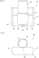
Fig. 9 is a side view of a pressing member. -
Fig. 10 is a top view of a pressing member. -
Fig. 11 is a rear view of a pressing member. - Embodiments of the present invention will now be described in detail below, with reference to the attached drawings.
- As shown in
Fig. 1 , acutting tool 100 according to this embodiment has atool body 10 and cuttinginserts 40. Thetool body 10 includes pressingmembers 50 andfastening components 70. - In the
cutting tool 100, a plurality ofcutting inserts 40 is mounted to the leading end of thetool body 10, and thecutting inserts 40 are radially arranged with a space in the circumferential direction. Thecutting tool 100 is a milling tool, such as an indexable cutter, and it cuts, while rotating, a workpiece with thecutting inserts 40 at the leading end of thetool body 10. This embodiment describes an example in which thecutting inserts 40 serve as cutting elements mounted to thetool body 10, but the present invention also includes embodiments in which a cartridge havingcutting inserts 40 incorporated therein is used as a cutting element. - The
tool body 10 has abase 11 which is generally cylindrical in shape. Thebase 11 is attached to a rotation shaft of a machine tool, such as a machining center. - As shown in
Figs. 2-4 , thebase 11 of thetool body 10 has a plurality ofpockets 12 formed at its leading end. A pressingmember 50 and afastening component 70 are placed in eachpocket 12. Thepocket 12 has a mountingpart 13. Themounting part 13 may be formed in, for example, a groove shape or a recessed shape, and acutting insert 40 is placed in themounting part 13. Upon being placed in themounting part 13, thecutting insert 40 is fixed by thepressing member 50 and thefastening component 70. - The mounting
part 13 has amounting surface 13a and acontact surface 13b. When acutting insert 40 is received in themounting part 13, thecutting insert 40 comes into contact with themounting surface 13a and thecontact surface 13b. Themounting part 13 is open at the leading end side of thebase 11 and has apositioning surface 13c that is formed at the rear end side of thebase 11. - The
pockets 12 each have a wedge-receivingpart 21 and afastening hole 22. The wedge-receivingpart 21 is formed on the mountingpart 13 side in thepocket 12, while thefastening hole 22 is formed on a side opposite to the mountingpart 13 with respect to the wedge-receivingpart 21. The wedge-receivingpart 21 and thefastening hole 22 are formed so as to be gradually inclined toward the mountingpart 13 side in a direction heading to the radial center of the base 11 (i.e., a direction heading deep into the base 11) (seeFig. 3 ). The depth of the wedge-receivingpart 21 is greater than that of themounting part 13, and aretention hole 22a (described below) of thefastening hole 22 is formed so as to be deeper than the wedge-receivingpart 21. - The wedge-receiving
part 21 has a slidingsurface 21a on a side opposite to the mountingpart 13. The wedge-receivingpart 21 also has aguide ridge 21b which is formed on each of the inner side surfaces on themounting part 13 side and extends in the depth direction. - The
fastening hole 22 is comprised of aretention hole 22a, a threadedhole 22b and anentrance hole 22c which are arranged in this order from the bottom, and the diameters of these holes gradually increase from the bottom (i.e., from theretention hole 22a to theentrance hole 22c). A female thread is formed on the inner surface of the threadedhole 22b. - The threaded
hole 22b and theentrance hole 22c are each formed so that a portion of their circumference communicates with the wedge-receivingpart 21. Theretention hole 22a is formed so that a portion of its circumference communicates with the wedge-receivingpart 21 on a side that continues to the threadedhole 22b. - The cutting
insert 40 has ametal base 41 and a cuttingtip 42. Themetal base 41 is formed in the shape of a rectangular plate and the cuttingtip 42 is provided at a corner on the upper surface of themetal base 41.Such cutting tip 42 provided on themetal base 41 may be, for example, a cutting tip made of single-crystal diamond or a sintered body of diamond (PCD: polycrystalline diamond). - The cutting
insert 40 is mounted to the mountingpart 13 of thepocket 12 and such mounting starts from an end of the cuttinginsert 40 that is opposite to the cuttingtip 42. The cuttinginsert 40 is gradually thickened toward the direction in which the cuttinginsert 40 is mounted to the mountingpart 13. - As illustrated in
Figs. 5-11 , the pressingmember 50 serves as a member that is inserted into thepocket 12 of thebase 11 of thetool body 10 so as to press and fix the cuttinginsert 40 that is placed in the mountingpart 13 of thepocket 12 towards the mountingsurface 13a of the mountingpart 13. - The pressing
member 50 has awedge part 51 and a pressure-receivingpart 52. Upon the pressingmember 50 being inserted into thepocket 12, thewedge part 51 is inserted into the wedge-receivingpart 21 and the pressure-receivingpart 52 is inserted into thefastening hole 22. - The
wedge part 51 has a contactingsurface 55 and apressing surface 56. The contactingsurface 55 comes into contact with the slidingsurface 21a of the wedge-receivingpart 21, which is an inner surface of thepocket 12, and thepressing surface 56 is in contact with the cuttinginsert 40 placed in the mountingpart 13. Thewedge part 51 is formed in a wedge shape in which its thickness gradually decreases in the insertion direction D into the pocket 12 (seeFig. 3 ). Accordingly, in thewedge part 51, thepressing surface 56 is inclined relative to the contactingsurface 55 in a manner so as to gradually come close to the contactingsurface 55 in the insertion direction D into thepocket 12. Thewedge part 51 has a thickest portion at its rear end in the insertion direction D, and the thickness of the thickest portion is set so as to be smaller than the diameter of thefastening component 70. - The
wedge part 51 hasprojections 57 that protrude outward on both sides of thewedge part 51. Theprojections 57 are formed so as to be parallel to the contactingsurface 55 along the insertion direction D of thewedge part 51 into thepocket 12. The upper and lower corners of eachprojection 57 are formed so as to be recessed in a circular-arc shape (seeFig. 11 ). The upper and lower corners of theprojections 57 may be formed in a tapered shape. - The pressure-receiving
part 52 has a cylindrical shape and it is formed integrally with the contactingsurface 55 side of thewedge part 51. The pressure-receivingpart 52 is disposed on the front side of thewedge part 51 in the insertion direction D, and part of the pressure-receivingpart 52 protrudes forward relative to thewedge part 51 in the insertion direction D. The center axis of the pressure-receivingpart 52 is parallel to the contactingsurface 55 of thewedge part 51. - The pressing
member 50 also has a receivingrecess 60 formed in thewedge part 51. A portion of thefastening component 70 is received in the receivingrecess 60. The receivingrecess 60 is formed on the contactingsurface 55 side of thewedge part 51 and recessed in a circular-arc shape in its cross-section. A front-side wall surface in the insertion direction D of the receivingrecess 60 is configured so as to be flush with an end surface of the pressure-receivingpart 52 and serves, together with such end surface of the pressure-receivingpart 52, as a pushingsurface 61. A rear-side wall surface in the insertion direction D of the receivingrecess 60 serves as a withdrawal surface 62 (seeFig. 8 ). Additionally, aclearance recess 63 is formed at an upper edge of the rear-side wall in the insertion direction D of the receivingrecess 60. - The
fastening component 70 is received in the receivingrecess 60 of the pressingmember 50 and it may be, for example, a socket set screw having a male thread on its outer circumference.Such fastening component 70 has atool hole 71 formed on its rear end surface so that a tool engages with thetool hole 71. Thetool hole 71 is not limited to being a hexagonal hole engageable with a hexagonal wrench and it may have various shapes for engagement with various types of tools, such as a hole in the Torx shape. Thefastening component 70 can be screw-engaged in the threadedhole 22b formed in thefastening hole 22 of thepocket 12. - The
fastening component 70 has a larger diameter than that of the pressure-receivingpart 52 of the pressingmember 50 and, when thefastening component 70 is received in the receivingrecess 60, the respective center axes of thefastening component 70 and the pressure-receivingpart 52 coincide with each other. It should be noted, however, that the center axes of thefastening component 70 and the pressure-receivingpart 52 may not necessarily coincide with each other. Further, in a state where thefastening component 70 is received in the receivingrecess 60, the circumscribed circle of thetool hole 71 of thefastening component 70, being a trajectory of rotation of thetool hole 71, does not overlap with the rear-side wall in the insertion direction D of the receivingrecess 60, which has theclearance recess 63 formed at its upper edge. With this configuration, when a tool is inserted into thetool hole 71, such tool does not interfere with the rear-side wall in the insertion direction D of the receivingrecess 60. By forming theclearance recess 63 at the rear-side wall in the insertion direction D of the receivingrecess 60 in this manner, thewedge part 51 of the pressingmember 50 can be made even thinner, although such wedge part is otherwise difficult to make thinner due to interference with a tool. - An example of the process for mounting a cutting
insert 40 into apocket 12 provided at thebase 11 of thetool body 10 will be described next. - First, a pressing
member 50 is inserted into apocket 12 of thebase 11 of thetool body 10, with afastening component 70 being received in the receivingrecess 60 of the pressingmember 50. More specifically, while the end of the pressure-receivingpart 52 of the pressingmember 50 is inserted into theretention hole 22a in thefastening hole 22 of thepocket 12, thewedge part 51 of the pressingmember 50 is inserted into the wedge-receivingpart 21 of thepocket 12, and thefastening component 70 is loosely screw-engaged in the threadedhole 22b. In this state, theprojections 57 on both sides of thewedge part 51 are stopped by theguide ridges 21b of the wedge-receivingpart 21, so that the pressingmember 50 is maintained in a state of being placed in thepocket 12. - Next, a cutting
insert 40 is inserted and placed in the mountingpart 13 of thepocket 12. With this insertion, the cuttinginsert 40 is placed in contact with the mountingsurface 13a,contact surface 13b andpositioning surface 13c. The cuttinginsert 40 may be inserted and placed in the mountingpart 13 of thepocket 12 before the pressingmember 50 is inserted into thepocket 12. - After that, a tool is inserted into the
tool hole 71 of thefastening component 70 that is received in the receivingrecess 60 of the pressingmember 50, and thefastening component 70 is screwed into the threadedhole 22b formed in thefastening hole 22 of thepocket 12. - As the
fastening component 70 is screwed into the threadedhole 22b in this way, thefastening component 70 moves toward the back of thefastening hole 22. As a result, the pushingsurface 61 of the pressingmember 50 is pressed by thefastening component 70, and the pressingmember 50 is pushed into the back of thepocket 12. Upon this movement of the pressingmember 50, thewedge part 51 of the pressingmember 50 also moves to the back of the wedge-receivingpart 21, while allowing the contactingsurface 55 of thewedge part 51 to slide on the slidingsurface 21a of the wedge-receivingpart 21, so that thepressing surface 56 moves in a direction approaching the cuttinginsert 40, resulting in thepressing surface 56 coming into contact with themetal base 41 of the cuttinginsert 40. - When the
fastening component 70 is further screwed into the threadedhole 22b, themetal base 41 of the cuttinginsert 40 is pressed by thepressing surface 56 of thewedge part 51 of the pressingmember 50. With this pressing, the cuttinginsert 40 is tightly sandwiched and fixed between the mountingsurface 13a of the mountingpart 13 and thepressing surface 56 of thewedge part 51 of the pressingmember 50. As a result, the cuttinginsert 40 is fixed in thepocket 12 of thebase 11 of thetool body 10. - Since the pressing
member 50 has the structure of being pushed into thepocket 12 via thefastening component 70 as described above, the pressingmember 50 does not need to have a female thread portion with which a screw for pushing the pressingmember 50 into thepocket 12 is screw-engaged, and this means that the size of the pressingmember 50 can be reduced. - Furthermore, in a state where the cutting
insert 40 is fixed by the pressingmember 50, the contact position Cs between the pressure-receivingpart 52 of the pressingmember 50 and thefastening component 70 is located at a position that is opposed to the cuttinginsert 40 on a rear side relative to anend surface 40a (indicated by the dash-dot-dot line inFig. 3 ) of the cuttinginsert 40 in the insertion direction D into the mounting part 13 (seeFig. 3 ). This configuration allows for suppression of the bending moment which may be generated when the pressure-receivingpart 52 is pressed by thefastening component 70. In other words, the pressingmember 50 employs the design for suppression of the bending moment occurring upon fixation of the cuttinginsert 40, based on a consideration of stress relaxation. Accordingly, the pressingmember 50 can be reduced in size while still ensuring sufficient strength. - In a state where the cutting
insert 40 is fixed by the pressingmember 50, a portion of the end of the pressure-receivingpart 52 is inserted into theretention hole 22a of thefastening hole 22 of thepocket 12. In other words, a portion of the end of the pressure-receivingpart 52 is enclosed, over the entire circumference thereof, by the inner circumference of theretention hole 22a of the pocket 12 (seeFig. 3 ). This configuration allows for suppression of an inclination of the pressure-receivingpart 52 that is pressed by thefastening component 70, and as a result, the pressingmember 50 can be reduced in size while ensuring a sufficient pressing force being applied to the cuttinginsert 40 by thepressing surface 56 of thewedge part 51. - In a state where the cutting
insert 40 is fixed by the pressingmember 50, theprojections 57 on both sides of thewedge part 51 are spaced away from theguide ridges 21b of the wedge-receivingpart 21, i.e., theprojections 57 do not come into contact with thepocket 12. Accordingly, there is no degradation in the pressing force applied to the cuttinginsert 40, caused by interference of theprojections 57 with thepocket 12. - An example of the process for removing the cutting
insert 40 that has been fixed in thepocket 12 by means of the pressingmember 50 will be described next. - For removing the cutting
insert 40, thefastening component 70 is rotated in a reverse manner to the rotation that was made for fastening, by using the tool inserted in thetool hole 71. Upon this reverse rotation, thefastening component 70 that has been screwed into the threadedhole 22b formed in thefastening hole 22 of thepocket 12 is loosened and moves in the withdrawal direction, which is opposite to the insertion direction D. - Then, the loosened
fastening component 70 presses thewithdrawal surface 62 of the pressingmember 50, and the pressingmember 50 is pulled out from thepocket 12. With this movement, thepressing surface 56 of thewedge part 51 of the pressingmember 50 moves away from the cuttinginsert 40, which releases the pressing applied by the pressingmember 50 to the cuttinginsert 40. In this state, the cuttinginsert 40 placed in the mountingpart 13 of thepocket 12 is grasped and then removed out of the mountingpart 13. - Here, when the pressing
member 50 is pulled out from thepocket 12 together with thefastening component 70, theprojections 57 on both sides of thewedge part 51 are stopped via contact with theguide ridges 21b of the wedge-receivingpart 21. In other words, in the removal of the cuttinginsert 40, theprojections 57 formed on thewedge part 51 of the pressingmember 50 come into contact with theguide ridges 21b of thepocket 12, so that theprojections 57 are guided by theguide ridges 21b, which prevents thefastening component 70 from falling off the receivingrecess 60 due to inclination of the pressingmember 50. Accordingly, the pressingmember 50 is smoothly extracted from thepocket 12 together with thefastening component 70. It should be noted here that, in some cases, theprojections 57 formed on thewedge part 51 do not come into contact with theguide ridges 21b of thepocket 12, and this depends on the position of the pressingmember 50 when it is loosened with a tool. The cuttinginsert 40 may also be removed and replaced, while having the pressingmember 50 and thefastening component 70 in a loosened state, without completely removing them out of thepocket 12. - As described above, the pressing
member 50 according to this embodiment has a structure wherein thewedge part 51 of the pressingmember 50 is pushed into thepocket 12 upon the pressure-receivingpart 52 of the pressingmember 50 being pushed by thefastening component 70. Thus, the structure can eliminate the need to provide the pressingmember 50 with a female thread portion for screw-engagement with a screw for pushing the pressingmember 50 into thepocket 12, leading to a reduction in size of the pressingmember 50. Since the pressingmember 50 can be reduced in size as stated above, the number of the cutting inserts 40 mounted to thetool body 11 can be increased and the size of thetool body 11 itself can be reduced. - Moreover, the pressing
member 50 is configured so that the thickness of the thickest portion of thewedge part 51 is smaller than the diameter of thefastening component 70. In other words, the pressingmember 50 can be further reduced in size owing to a reduced thickness of thewedge part 51. - The present invention provides a pressing member, a tool body, and a cutting tool, achieving an increase in the number of cutting elements mounted and a reduction in size of the tool body.
Claims (10)
- A pressing member that is inserted into a pocket of a tool body for pressing and fixing a cutting element placed in a mounting part of the pocket onto a mounting surface of the mounting part, the pressing member comprising:a wedge part having a contacting surface that comes into contact with an inner surface of the pocket, and a pressing surface that is in contact with the cutting element, wherein the pressing surface is formed so as to gradually come close to the contacting surface in an insertion direction into the pocket; anda pressure-receiving part that is pushed into the pocket in the insertion direction by a fastening component that is screwed into the pocket.
- The pressing member according to claim 1, wherein, in a state where the cutting element is fixed, a contact position of the pressure-receiving part with the fastening component is located at a position that is opposed to the cutting element relative to a position of an end surface of the cutting element in an insertion direction into the mounting part.
- The pressing member according to claim 1 or 2, wherein, in a state where the cutting element is fixed, at least a portion of the pressure-receiving part is enclosed, over an entire circumference, by an inner circumference of a retention hole which is formed as a further recess that continues to the pocket.
- The pressing member according to claim 1, 2, or 3, wherein a thickest portion of the wedge part has a thickness smaller than a diameter of the fastening component.
- The pressing member according to any one of claims 1 to 4, wherein the wedge part has a receiving recess for receiving at least a portion of the fastening component, and
wherein a wall surface of the receiving recess at a rear side in the insertion direction is configured as a withdrawal surface that is pressed by the fastening component when the fastening component is loosened from the pocket. - The pressing member according to claim 5, wherein a wall surface of the receiving recess at a front side in the insertion direction is configured as a pushing surface that is pressed, along with the pressure-receiving part, by the fastening component.
- The pressing member according to any one of claims 1 to 6, wherein the wedge part has outwardly protruding projections formed on both sides of the wedge part.
- The pressing member according to claim 7, wherein the projections do not interfere with the pocket in a state where the cutting element is fixed, and
wherein the projections may come into contact with the pocket during removal of the cutting element. - A tool body comprising:a pressing member according to any one of claims 1 to 8;a base having a plurality of pockets into which the pressing member is inserted, the plurality of pockets being formed so as to be spaced apart in a circumferential direction; anda fastening component that is screwed into each of the pockets,wherein each of the pockets has a mounting part in which a cutting element is placed, andwherein the cutting element placed in the mounting part is pressed and fixed to a mounting surface of the mounting part when the pressing member inserted into the pocket is pressed in an insertion direction into the pocket by the fastening component screwed into the pocket.
- A cutting tool comprising:a tool body according to claim 9; anda cutting element placed in the mounting part of the pocket formed in the base of the tool body.
Applications Claiming Priority (1)
| Application Number | Priority Date | Filing Date | Title |
|---|---|---|---|
| JP2023202827A JP7529123B1 (en) | 2023-11-30 | 2023-11-30 | Pressing member, tool body and cutting tool |
Publications (1)
| Publication Number | Publication Date |
|---|---|
| EP4570404A1 true EP4570404A1 (en) | 2025-06-18 |
Family
ID=92144712
Family Applications (1)
| Application Number | Title | Priority Date | Filing Date |
|---|---|---|---|
| EP24215842.6A Pending EP4570404A1 (en) | 2023-11-30 | 2024-11-27 | Pressing member, tool body and cutting tool |
Country Status (3)
| Country | Link |
|---|---|
| US (1) | US20250178099A1 (en) |
| EP (1) | EP4570404A1 (en) |
| JP (1) | JP7529123B1 (en) |
Citations (7)
| Publication number | Priority date | Publication date | Assignee | Title |
|---|---|---|---|---|
| DE1921532A1 (en) * | 1968-06-04 | 1970-01-29 | Skoda Np | Device for clamping interchangeable multiple cutting inserts in milling cutters |
| US4575287A (en) * | 1982-06-11 | 1986-03-11 | Kennametal Inc. | Milling cutter and method of assembling therefor |
| US5904193A (en) * | 1995-04-15 | 1999-05-18 | Gebr. Leitz Gmbh & Co. | Cutter head, in particular a planing cutter head |
| JP2008526535A (en) | 2005-01-06 | 2008-07-24 | セイフティ プロダクション | Attaching the cutting plate to the tool holder |
| EP2377635A2 (en) * | 2002-04-29 | 2011-10-19 | Kennametal Inc. | Cutting tool |
| JP6860866B1 (en) | 2020-08-12 | 2021-04-21 | 株式会社タンガロイ | Cutting insert |
| WO2023058593A1 (en) | 2021-10-05 | 2023-04-13 | 日本特殊陶業株式会社 | Cutting holder and cutting tool |
Family Cites Families (10)
| Publication number | Priority date | Publication date | Assignee | Title |
|---|---|---|---|---|
| US4318647A (en) * | 1980-04-07 | 1982-03-09 | General Electric Company | Adjustable insert seat and wedge assembly for an indexable boring cutter |
| JPS62147419U (en) * | 1986-03-12 | 1987-09-17 | ||
| DE29508112U1 (en) * | 1995-05-17 | 1995-08-10 | Gebr. Leitz GmbH & Co, 73447 Oberkochen | Profile cutter head |
| JP3197476B2 (en) * | 1995-12-28 | 2001-08-13 | 兼房株式会社 | Milling cutter |
| JPH11277306A (en) * | 1998-03-26 | 1999-10-12 | Mitsubishi Materials Corp | Milling tool |
| JP2003275916A (en) | 2002-03-20 | 2003-09-30 | Mitsubishi Materials Corp | Replaceable cutting tool |
| US9211590B2 (en) | 2013-09-20 | 2015-12-15 | Kennametal Inc. | Screw head wedge clamp assembly for cutting tool |
| US10010953B2 (en) | 2014-03-19 | 2018-07-03 | Kennametal Inc. | Wedge clamp and insert cartridge for cutting tool |
| EP3069809B1 (en) | 2014-05-15 | 2021-10-20 | Tungaloy Corporation | Insert attachment mechanism and cutting tool |
| JP6327594B1 (en) | 2017-08-10 | 2018-05-23 | 株式会社タンガロイ | Cutting tools |
-
2023
- 2023-11-30 JP JP2023202827A patent/JP7529123B1/en active Active
-
2024
- 2024-10-31 US US18/933,715 patent/US20250178099A1/en active Pending
- 2024-11-27 EP EP24215842.6A patent/EP4570404A1/en active Pending
Patent Citations (7)
| Publication number | Priority date | Publication date | Assignee | Title |
|---|---|---|---|---|
| DE1921532A1 (en) * | 1968-06-04 | 1970-01-29 | Skoda Np | Device for clamping interchangeable multiple cutting inserts in milling cutters |
| US4575287A (en) * | 1982-06-11 | 1986-03-11 | Kennametal Inc. | Milling cutter and method of assembling therefor |
| US5904193A (en) * | 1995-04-15 | 1999-05-18 | Gebr. Leitz Gmbh & Co. | Cutter head, in particular a planing cutter head |
| EP2377635A2 (en) * | 2002-04-29 | 2011-10-19 | Kennametal Inc. | Cutting tool |
| JP2008526535A (en) | 2005-01-06 | 2008-07-24 | セイフティ プロダクション | Attaching the cutting plate to the tool holder |
| JP6860866B1 (en) | 2020-08-12 | 2021-04-21 | 株式会社タンガロイ | Cutting insert |
| WO2023058593A1 (en) | 2021-10-05 | 2023-04-13 | 日本特殊陶業株式会社 | Cutting holder and cutting tool |
Also Published As
| Publication number | Publication date |
|---|---|
| US20250178099A1 (en) | 2025-06-05 |
| JP2025088251A (en) | 2025-06-11 |
| JP7529123B1 (en) | 2024-08-06 |
Similar Documents
| Publication | Publication Date | Title |
|---|---|---|
| RU2465987C2 (en) | Mechanism for clamping cutting plate and perishable cutting tool furnished with said mechanism | |
| KR100316162B1 (en) | Indexed Insert Router | |
| RU2501633C2 (en) | Cutting tool clamp | |
| EP2066471B1 (en) | Cutting tool having cutting insert secured by non-penetrating abutment of a threaded fastener | |
| EP2617505B1 (en) | A hole-making tool | |
| KR20090055625A (en) | Cutting insert with elliptical cutting edge | |
| EP1375037A1 (en) | Insert, holder and cutting tool | |
| EP0051775B1 (en) | Toolholder for use in holding a cutting insert, method of clamping a cutting insert and locking pin for securing a cutting insert | |
| EP0798065A2 (en) | Drill and throwaway tip | |
| EP2420340B1 (en) | Thread-milling insert and thread-milling cutter | |
| CN1174529A (en) | Plunge and face milling cutters with universal insert pockets | |
| JP2007532332A (en) | Cutting tools and cutting inserts for cutting tools | |
| CZ2005581A3 (en) | Milling cutter and indexable cutting insert | |
| JP2016193461A (en) | Tip exchangeable drill | |
| CN107000076A (en) | Tools and cutting inserts for chip removal | |
| CZ2005580A3 (en) | Positionable cutting tip | |
| EP2105229A2 (en) | Throwaway insert and throwaway-type rotary cutting tool | |
| EP4570404A1 (en) | Pressing member, tool body and cutting tool | |
| EP4074442A1 (en) | Cutting insert and cutting tool | |
| US6695549B2 (en) | Cutting tool assembly | |
| KR20120043736A (en) | Miling tool, in particular a thread milling tool | |
| US10385904B2 (en) | Press nut designs to minimize stack thickness | |
| JPH04228912A (en) | Clamping tool | |
| JP2020163524A (en) | Replaceable cutting tools, cutting inserts, and tool bodies | |
| JP2006247790A (en) | Throw-away cutting tool |
Legal Events
| Date | Code | Title | Description |
|---|---|---|---|
| PUAI | Public reference made under article 153(3) epc to a published international application that has entered the european phase |
Free format text: ORIGINAL CODE: 0009012 |
|
| STAA | Information on the status of an ep patent application or granted ep patent |
Free format text: STATUS: REQUEST FOR EXAMINATION WAS MADE |
|
| 17P | Request for examination filed |
Effective date: 20241214 |
|
| AK | Designated contracting states |
Kind code of ref document: A1 Designated state(s): AL AT BE BG CH CY CZ DE DK EE ES FI FR GB GR HR HU IE IS IT LI LT LU LV MC ME MK MT NL NO PL PT RO RS SE SI SK SM TR |