EP4570376A1 - Liquid feeder - Google Patents
Liquid feeder Download PDFInfo
- Publication number
- EP4570376A1 EP4570376A1 EP24209204.7A EP24209204A EP4570376A1 EP 4570376 A1 EP4570376 A1 EP 4570376A1 EP 24209204 A EP24209204 A EP 24209204A EP 4570376 A1 EP4570376 A1 EP 4570376A1
- Authority
- EP
- European Patent Office
- Prior art keywords
- needle
- liquid
- cap
- sealing member
- container
- Prior art date
- Legal status (The legal status is an assumption and is not a legal conclusion. Google has not performed a legal analysis and makes no representation as to the accuracy of the status listed.)
- Pending
Links
Images









Classifications
-
- B—PERFORMING OPERATIONS; TRANSPORTING
- B01—PHYSICAL OR CHEMICAL PROCESSES OR APPARATUS IN GENERAL
- B01L—CHEMICAL OR PHYSICAL LABORATORY APPARATUS FOR GENERAL USE
- B01L3/00—Containers or dishes for laboratory use, e.g. laboratory glassware; Droppers
- B01L3/52—Containers specially adapted for storing or dispensing a reagent
- B01L3/523—Containers specially adapted for storing or dispensing a reagent with means for closing or opening
-
- B—PERFORMING OPERATIONS; TRANSPORTING
- B65—CONVEYING; PACKING; STORING; HANDLING THIN OR FILAMENTARY MATERIAL
- B65D—CONTAINERS FOR STORAGE OR TRANSPORT OF ARTICLES OR MATERIALS, e.g. BAGS, BARRELS, BOTTLES, BOXES, CANS, CARTONS, CRATES, DRUMS, JARS, TANKS, HOPPERS, FORWARDING CONTAINERS; ACCESSORIES, CLOSURES, OR FITTINGS THEREFOR; PACKAGING ELEMENTS; PACKAGES
- B65D51/00—Closures not otherwise provided for
- B65D51/18—Arrangements of closures with protective outer cap-like covers or of two or more co-operating closures
- B65D51/20—Caps, lids, or covers co-operating with an inner closure arranged to be opened by piercing, cutting, or tearing
- B65D51/22—Caps, lids, or covers co-operating with an inner closure arranged to be opened by piercing, cutting, or tearing having means for piercing, cutting, or tearing the inner closure
-
- B—PERFORMING OPERATIONS; TRANSPORTING
- B01—PHYSICAL OR CHEMICAL PROCESSES OR APPARATUS IN GENERAL
- B01L—CHEMICAL OR PHYSICAL LABORATORY APPARATUS FOR GENERAL USE
- B01L3/00—Containers or dishes for laboratory use, e.g. laboratory glassware; Droppers
- B01L3/56—Labware specially adapted for transferring fluids
- B01L3/563—Joints or fittings; Separable fluid transfer means to transfer fluids between at least two containers, e.g. connectors
-
- G—PHYSICS
- G01—MEASURING; TESTING
- G01N—INVESTIGATING OR ANALYSING MATERIALS BY DETERMINING THEIR CHEMICAL OR PHYSICAL PROPERTIES
- G01N35/00—Automatic analysis not limited to methods or materials provided for in any single one of groups G01N1/00 - G01N33/00; Handling materials therefor
- G01N35/10—Devices for transferring samples or any liquids to, in, or from, the analysis apparatus, e.g. suction devices, injection devices
-
- G—PHYSICS
- G01—MEASURING; TESTING
- G01N—INVESTIGATING OR ANALYSING MATERIALS BY DETERMINING THEIR CHEMICAL OR PHYSICAL PROPERTIES
- G01N35/00—Automatic analysis not limited to methods or materials provided for in any single one of groups G01N1/00 - G01N33/00; Handling materials therefor
- G01N35/10—Devices for transferring samples or any liquids to, in, or from, the analysis apparatus, e.g. suction devices, injection devices
- G01N35/1002—Reagent dispensers
-
- B—PERFORMING OPERATIONS; TRANSPORTING
- B01—PHYSICAL OR CHEMICAL PROCESSES OR APPARATUS IN GENERAL
- B01L—CHEMICAL OR PHYSICAL LABORATORY APPARATUS FOR GENERAL USE
- B01L2200/00—Solutions for specific problems relating to chemical or physical laboratory apparatus
- B01L2200/02—Adapting objects or devices to another
- B01L2200/025—Align devices or objects to ensure defined positions relative to each other
-
- B—PERFORMING OPERATIONS; TRANSPORTING
- B01—PHYSICAL OR CHEMICAL PROCESSES OR APPARATUS IN GENERAL
- B01L—CHEMICAL OR PHYSICAL LABORATORY APPARATUS FOR GENERAL USE
- B01L2200/00—Solutions for specific problems relating to chemical or physical laboratory apparatus
- B01L2200/06—Fluid handling related problems
- B01L2200/0684—Venting, avoiding backpressure, avoid gas bubbles
-
- B—PERFORMING OPERATIONS; TRANSPORTING
- B01—PHYSICAL OR CHEMICAL PROCESSES OR APPARATUS IN GENERAL
- B01L—CHEMICAL OR PHYSICAL LABORATORY APPARATUS FOR GENERAL USE
- B01L2300/00—Additional constructional details
- B01L2300/04—Closures and closing means
- B01L2300/041—Connecting closures to device or container
- B01L2300/044—Connecting closures to device or container pierceable, e.g. films, membranes
-
- B—PERFORMING OPERATIONS; TRANSPORTING
- B01—PHYSICAL OR CHEMICAL PROCESSES OR APPARATUS IN GENERAL
- B01L—CHEMICAL OR PHYSICAL LABORATORY APPARATUS FOR GENERAL USE
- B01L2300/00—Additional constructional details
- B01L2300/04—Closures and closing means
- B01L2300/046—Function or devices integrated in the closure
- B01L2300/048—Function or devices integrated in the closure enabling gas exchange, e.g. vents
-
- B—PERFORMING OPERATIONS; TRANSPORTING
- B01—PHYSICAL OR CHEMICAL PROCESSES OR APPARATUS IN GENERAL
- B01L—CHEMICAL OR PHYSICAL LABORATORY APPARATUS FOR GENERAL USE
- B01L2300/00—Additional constructional details
- B01L2300/06—Auxiliary integrated devices, integrated components
- B01L2300/0672—Integrated piercing tool
-
- B—PERFORMING OPERATIONS; TRANSPORTING
- B01—PHYSICAL OR CHEMICAL PROCESSES OR APPARATUS IN GENERAL
- B01L—CHEMICAL OR PHYSICAL LABORATORY APPARATUS FOR GENERAL USE
- B01L2400/00—Moving or stopping fluids
- B01L2400/04—Moving fluids with specific forces or mechanical means
- B01L2400/0403—Moving fluids with specific forces or mechanical means specific forces
- B01L2400/0457—Moving fluids with specific forces or mechanical means specific forces passive flow or gravitation
-
- B—PERFORMING OPERATIONS; TRANSPORTING
- B01—PHYSICAL OR CHEMICAL PROCESSES OR APPARATUS IN GENERAL
- B01L—CHEMICAL OR PHYSICAL LABORATORY APPARATUS FOR GENERAL USE
- B01L2400/00—Moving or stopping fluids
- B01L2400/06—Valves, specific forms thereof
- B01L2400/0677—Valves, specific forms thereof phase change valves; Meltable, freezing, dissolvable plugs; Destructible barriers
- B01L2400/0683—Valves, specific forms thereof phase change valves; Meltable, freezing, dissolvable plugs; Destructible barriers mechanically breaking a wall or membrane within a channel or chamber
Definitions
- the present invention relates to a liquid feeder for use in an automated analyzer.
- An automated analyzer is an instrument for quickly and accurately analyzing multiple components contained in an analyte, and is used in various fields including biochemical examinations and blood transfusion examinations. Furthermore, an automated analyzer is equipped with a measuring section for measuring analytes. In the measuring section, liquids such as diluents and cleaning liquids are used. These liquids are stored in reservoirs equipped in the automated analyzer. The liquids stored in the reservoirs are fed into given sections using pumps and tubes, for example.
- the automated analyzer has a liquid feeder for feeding the liquid into the reservoir.
- patent document 1 discloses a configuration having ports formed in an upper portion and a lower portion, respectively, of a liquid container. A threaded cap is attached to the upper port. A septum and the cap are attached to the lower port. Patent document 1 also discloses a configuration using a mounting bracket in which a liquid container is set. A needle is mounted at the bottom of the bracket and operative to pierce the septum.
- Patent document 1 Japanese Patent No. 4,945,572
- the two ports are formed in the liquid container. Therefore, if the liquid container is fabricated by blow molding, for example, the fabrication is made more difficult. Also, the cost of fabrication of the liquid container increases. Furthermore, with the technique set forth in patent document 1, when the needle pierces the septum, the user needs to loosen the threaded cap plugging up the upper port in order to cause air to flow into the liquid container so that the liquid inside the liquid container flows down through the needle. Therefore, in view of the user's operability, there is a problem to be remedied.
- the present invention has been made to solve the above-described problem. It is an object of the present invention to provide a liquid feeder which can reduce the number of ports formed in a liquid container and which can alleviate the burden imposed on the user's operability.
- a liquid feeder associated with the present invention comprises: a liquid container having (i) a container body provided with a port and operative to receive a liquid, (ii) a sealing member for sealing the port of the container body, and (iii) a cap for securing the sealing member to the port; and a container holding portion for holding the liquid container while the cap is placed downward.
- the container holding portion has: a cap receiving portion that forms a space capable of accepting the cap; and a needle disposed in the space formed by the cap receiving portion.
- the sealing member is made of a resilient material and has slitted portions.
- the cap is made of a hard material and has a cover portion disposed opposite to the sealing member.
- the cover portion has groove portions formed by partially reducing the cover portion in thickness.
- the cover portion of the cap is so configured as to be split along the groove portions when the needle pushes against the cover portion.
- the sealing member is so configured that the slitted portions are spread apart when the needle pushes against the sealing member.
- the number of ports formed in the liquid container can be reduced. Also, the burden on the user's manipulation can be alleviated.
- FIG. 1 is a cross-sectional view showing the configuration of a liquid feeder, 10, associated with a first embodiment of the present invention.
- FIG. 2 is an enlarged view of a portion of the liquid feeder 10 of FIG. 1 .
- the up/down direction is parallel to a vertical direction
- the left/right direction is parallel to a horizontal direction.
- the liquid feeder 10 includes a liquid container 11, a container holding portion 12 for holding the liquid container 11, and a liquid reservoir 13 for storing the liquid flowing downward from the liquid container 11.
- the liquid feeder 10 is equipped, for example, in an automated analyzer that uses liquids such as various diluents and cleaning liquids.
- the liquid feeder 10 may also be an instrument other than an automated analyzer, and may be equipped in various instruments handling different kinds of liquid. In the present embodiment, it is assumed that the liquid feeder 10 is equipped in an automated analyzer.
- an automated analyzer is an instrument for quickly and accurately analyzing multiple components contained in an analyte, and is used in various fields including biochemical examinations and blood transfusion examinations.
- a single automated analyzer is equipped with a plurality of liquid feeders 10. Also, of the components of each liquid feeder 10, the liquid container 11 is replaceable, and the container holding portion 12 and reservoir 13 are always in position within the liquid feeder 10.
- the liquid container 11 is detachably mounted to the container holding portion 12.
- the container 11 When the liquid container 11 is set in the container holding portion 12, the container 11 is inserted from above to below into the container holding portion 12.
- the container 11 When the liquid container 11 is taken out of the container holding portion 12, the container 11 is pulled up from the container holding portion 12.
- FIGS. 1 and 2 show a state in which the liquid container 11 is being inserted into the container holding portion 12 to set the container 11 in the holding portion 12.
- the liquid container 11 has a container body 15, a sealing member 16, and a cap 17.
- the container body 15 is made of a bottle that accommodates a liquid.
- the bottle acting as the container body 15 is treated, for example, as a disposable or replaceable bottle.
- the sealing member 16 and the cap 17 are treated as disposable members in the same manner as the above-described replaceable bottle.
- the container body 15 may not be disposable but rather made reusable by cleaning or otherwise processing it.
- the bottle serving as the container body 15 is fabricated by blow molding, for example.
- the container body 15 is a hollow body having a capacity to receive a given amount of liquid.
- the container body 15 has a port 21 and a grip portion 22 (see FIG. 1 ) which are integral with each other.
- the body port 21 is disposed downward.
- the port 21 is shaped cylindrically.
- An external thread 23 (see FIG. 2 ) is formed on the outer surface of the body port 21.
- the grip portion 22 is disposed on the opposite side of the body port 21 as viewed in the up/down direction in FIG. 1 .
- a tab 24 (see FIG. 1 ) is formed integrally with the liquid container 11 to make it possible to detect whether the liquid container 11 has been set in the container holding portion 12, i.e., a sensor (not shown) detects the presence or absence of the liquid container 11.
- the tab 24 is mounted to the liquid container 11 but the present invention is not restricted to this example.
- it may be detected as to whether the liquid container 11 has been set in the container holding portion 12 via a separate member.
- a rotatable member comes into contact with the liquid container 11 and rotates.
- a sensor detects the rotation of this rotatable member, whereby detecting whether the liquid container 11 has been set in the container holding portion 12.
- the sensor may be an optical sensor consisting of a light emitter emitting light and a light receiver detecting the light from the light emitter.
- the rotatable member When the liquid container 11 is set and the rotatable member rotates, this rotating member blocks the light from the light emitter. Consequently, it is possible to detect that the liquid container 11 has been set in the container holding portion 12.
- the rotatable member is preferably an opaque member that does not transmit light.
- the sealing member 16 serves to seal off the port 21 of the liquid container 11 and is made of a resilient material such as a synthetic resin. That is, the sealing member 16 is a rubberlike resilient body. The sealing member 16 is placed in intimate contact with an end surface 21a (see FIG. 2 ) of the body port 21.
- FIG. 3 is a perspective view showing the configuration of the sealing member 16 of the liquid feeder associated with the first embodiment of the present invention.
- the sealing member 16 is shaped in the form of a circular disk having a given thickness.
- the sealing member 16 is provided with slitted portions 26 which extend thicknesswise through the sealing member 16. The surfaces forming the slitted portions 26a-26d are kept in intimate contact with each other by the resilience of the sealing member 16.
- the slitted portions 26a-26d in the sealing member 16 extend radially outwardly from a central portion of the sealing member 16.
- four slitted portions 26a-26d are formed as an example in the sealing member 16 and arranged rotationally symmetrically and in a crisscross manner.
- the sealing member 16 is so configured that a needle 70 (see FIGS. 1 and 2 ) pushes against the sealing member 16 to thereby spread the slitted portions 26a-26d apart as shown in FIG. 4 .
- the sealing member 16 is also configured so that, when the needle 70 is pulled out of the sealing member 16, the resilience of the sealing member 16 closes the slitted portions 26a-26d.
- the structure of the needle 70 is described in further detail later.
- the thickness t of the sealing member 16 is preferably between 3 mm and 7 mm as shown in FIG. 3 .
- the needle 70 has a radius of r in mm
- the length L in mm of each of the slitted portions 26a-26d preferably satisfies Eq. (1) below.
- the radius r of the needle 70 is the radius of the stem 71 of the needle 70 shown in FIGS. 12 and 13 . r + t ⁇ L ⁇ 5 t
- each of the slitted portions 26a-26d satisfies Eq. (1) above, the following advantages arise.
- the gaps are formed around the needle 70 because each of the slitted portions 26a-26d is spread apart into a V-shaped form as viewed along the central axis of the needle 70.
- the given gaps between the successive ones of the slitted portions 26a-26d can be used as air and fluid passages.
- the resilience of the sealing member 16 restores the slitted portions 26a-26d into their original state, i.e., before spread apart by the needle 70, and closes the given gaps. Therefore, when the needle 70 is pulled out of the sealing member 16, leakage of liquid from the slitted portions 26a-26d can be suppressed.
- the four slitted portions 26a-26d are formed in the sealing member 16 and arranged in a crisscross fashion.
- the present invention is not restricted to this example.
- three slitted portions may be formed in the sealing member 16 so as to be circumferentially equally spaced from each other about a central portion of the sealing member 16.
- the sealing member 16 may be provided with five or more slitted portions.
- the four slitted portions 26a-26d extend thicknesswise through the sealing member 16.
- the present invention is not restricted to this example.
- the slitted portions 26a-26d may depthwise extend not fully through the sealing member 16 such that thin-walled portions are left in the deepest portions of the slitted portions 26a-26d.
- the performance of the sealing member 16 in terms of sealing the port 21 during transportation or storage of the liquid container 11 can be enhanced.
- the needle 70 see FIGS. 1 and 2
- the slitted portions 26a-26d can be pushed and spread out by the needle 70.
- the cap 17 is a member mounted to the port 21 of the container body 15 in order to attach the sealing member 16 to the port 21.
- the cap 17 is made of a hard material such as a hard resin (e.g., polypropylene).
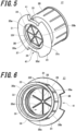
- FIG. 5 is a perspective view of the cap 17 equipped in the liquid feeder associated with the first embodiment of the present invention, as viewed from the outside of the container body 15 (i.e., from the underside of FIG. 1 ).
- FIG. 6 is a perspective view of the cap 17 of FIG. 1 , as viewed from the inside of the container body 15 (i.e., from the top side of FIG. 1 ).
- FIG. 7 is a plan view of the cap 17 of the liquid feeder of FIG. 1 .
- FIG. 8 is a cross-sectional view of the cap 17 of FIG. 7 , taken on line A-A.
- FIG. 9 is an enlarged view of portion B of FIG. 8 .
- the cap 17 has a cylindrical sidewall 28, a cover portion 29 closing off one opening of the sidewall 28, a toroidal portion 30 radially inwardly protruding from the inner side surface of the sidewall 28, and a flange portion 31 protruding radially outwardly of the outer surface of the sidewall 28.
- the cap 17 is unitarily molded from a resin.
- an internal thread 32 is formed together with the toroidal portion 30.
- the cap 17 When the cap 17 is mounted to the port 21 of the container body 15, the internal thread 32 engages the external thread 23 on the port 21. By bringing the internal thread 32 into engagement with the external thread 23 on the port 21 as shown in FIG. 2 and tightening the cap 17, the cap 17 is clampingly secured against the port 21 of the liquid container 11. As described previously, the toroidal portion 30 pushes the sealing member 16 against the end surface 21a of the port 21 by tightening the cap 17.
- the cap 17 When the cap 17 is mounted to the port 21 of the container body 15, the port 21 is placed upward. In this case, the sealing member 16 is disposed between the end surface 21a of the port 21 and the toroidal portion 30 of the cap 17. Under this condition, the cap 17 is tightened, whereby the sealing member 16 is secured to the end surface 21a of the port 21 while in intimate contact with it.
- the cover portion 29 is disposed opposite to the sealing member 16 as shown in FIG. 2 .
- the cover portion 29 appears to be circular in shape.
- the cover portion 29 is shaped in a disklike form.
- the cover portion 29 is placed a given distance (described later) from the sealing member 16.
- Groove portions 35 are formed in the cover portion 29 by partially reducing the thicknesswise dimension of the cover portion 29. Therefore, the parts of the cover portion 29 which have the groove portions 35 provide lower mechanical strength than the other parts. However, the cover portion 29, including the parts where the groove portions 35 are formed, has no through-holes extending thicknesswise. Therefore, when the port 21 of the container body 15 is sealed by the sealing member 16 and tightened by the cap 17, it follows that the port 21 is sealed doubly by the sealing member 16 and the cap 17. This can enhance the sealability of the liquid container 11 during transportation or storage.
- the cover portion 29 has the plural groove portions 35 (35a-35f) extending radially outwardly from a central portion of the cover portion 29.
- the groove portions 35 (35a-35f) are so formed that when the needle 70 pushes against the cover portion 29, the cover portion 29 is split along the groove portions 35a-35f.
- 6 groove portions 35a-35f are formed in the cover portion 29 as an example.
- the 6 groove portions 35a-35f are formed rotationally symmetrically and arranged radially.
- each of the groove portions 35a-35f has a V-shaped cross-sectional shape. They may also have other cross-sectional shape, such as a U-shaped cross-sectional shape.
- the cover portion 29 has a first surface 36 (see FIGS. 6 and 8 ) and a second surface 37 (see FIGS. 5and 8 ) which are disposed on opposite sides of each other, the first surface 36 being opposite to the sealing member 16.
- first surface 36 of the cover portion 29 acts as the inner surface of the cover portion 29 that faces into the container body 15 while the second surface 37 of the cover portion 29 serves as the outer surface of the cover portion 29 that faces outside of the container body 15.
- the six groove portions 35a-35f are formed in both first surface 36 and second surface 37.
- the groove portions 35a-35f in the first surface 36 have the same depth as the groove portions 35a-35f in the second surface 37. Note that the depth of the groove portions 35a-37f in the first surface 36 may be different from the depth of the groove portions 35a-35f in the second surface 37.
- the 6 groove portions 35a-35f are formed at their respective corresponding positions in the first surface 36 and the second surface 37. That is, if the cap 17 is seen through from the front side, they would be in registry with each other.
- Thin-walled portions 38 are formed in the central portion of the cover portion 29 to suppress positional deviations of the needle 70.
- the thin-walled portions 38 are formed in both first surface 36 and second surface 37 in the same way as the above-described 6 groove portions 35a-35f.
- the thin-walled portions 38 are shaped substantially circularly.
- the depth of the thin-walled portions 38 in the first surface 36 is the same as that of the groove portions 35a-35f in the first surface 36.
- the depth of the thin-walled portions 38 in the second surface 37 is the same as that of the groove portions 35a-35f in the second surface 37.
- Second groove portions 39 are formed in the second surface 37 of the cover portion 29 as shown in FIG. 5 .
- the second groove portions 39 are not formed in the first surface 36 of the cover portion 29 as shown in FIG. 6 .
- the second groove portions 39 facilitate splitting of the cover portion 29 along the groove portions 35a-35f and prevent fragments of the split cover portion 29 from separating from the cap 17.
- the second groove portions 39 in the second surface 37 have the same depth as that of the groove portions 35a-35f in the second surface 37.
- the second surface 37 is so formed as to interconnect the radially outer ends of the groove portions 35a-35f formed in the second surface 37.
- the six groove portions 35a-35f are formed in the second surface 37.
- the overall arrangement of the second groove portions 39 is hexagonal in shape as viewed from the front of the cap 17.
- the shape of the overall arrangement of the second groove portions 39 is not restricted to a hexagon but rather may be a polygon corresponding to the number of groove portions formed in the second surface 37.
- the overall arrangement of the second groove portions 39 is shaped tetragonally in a manner not illustrated.
- the second groove portions 39 may be circular in shape regardless of the number of groove portions formed in the second surface 37.
- Plural cutout portions 41 are formed in the flange portion 31.
- two cutout portions 41 are formed on the circumference of the flange portion 31 as an example.
- the two cutout portions 41 are spaced 180° from each other circumferentially of the cap 17.
- the cutout portions 41 have a given circumferential width.
- the positions of the cutout portions 41, i.e., slit positions, as taken circumferentially of the cap 17 are determined according to the type of liquid received in the container body 15.
- the number of the cutout portions 41 may be either one or three or more.
- the positions of the cutout portions 41 as taken circumferentially of the cap 17 can be brought to preliminarily assumed positions by either causing a portion of the cap 17 to strike the end surface 21a (see FIG. 2 ) of the port 21 or controlling the tightening torque on the cap 17.
- the cutout portions 41 in the flange portion 31 are formed to prevent incorrect insertion of any liquid container 11 that is different from the liquid container 11 to be inserted and set in the container holding portion 12.
- the liquid container 11 receiving the first diluting fluid should be inserted in the container holding portion 12 but the user might incorrectly insert the liquid container 11 receiving the second diluting fluid.
- Such incorrect insertion of the liquid container 11 is prevented by mechanical interference between the flange portion 31 and keys 56 (described later) (see FIG. 10 ).
- the container holding portion 12 holds the liquid container 11 while the cap 17 is placed downward.
- the container holding portion 12 has a housing 45 and a manifold 46.
- the manifold 46 is tightened and secured to the bottom or a lower portion of the housing 45 with a plurality of bolts 47.
- a ring-shaped sealing member 48 is mounted inside the tightening positions of the bolts 47 and suppresses leakage of gas and liquid at the contact interface between the housing 45 and the manifold 46.
- the housing 45 has sufficient rigidity to hold the container body 15 in which a given amount of liquid is received.
- the housing 45 has the above-described case portion 51 forming a space capable of receiving the container body 15, a container receiving portion 52 formed at the bottom of the case portion 51, and a connector portion 53 connected to the manifold 46. All of these portions 51-53 are formed integrally.
- the liquid container 11 which is inserted and set in the container holding portion 12 is received and supported from below by the container receiving portion 52.
- the bottom surface of the container body 15 is received and supported from below outside of the body port 21 by the container receiving portion 52.
- the whole mass of the liquid container 11 including the mass of the liquid received in the container body 15 acts on the container receiving portion 52.
- FIG. 10 is a cross-sectional view of the liquid feeder 10 of FIG. 1 , taken on line C-C.
- a plurality of key mounting portions 55 are formed on the same circumferential surface as the container receiving portion 52.
- One key 56 is detachably attached to each key mounting portion 55.
- the keys 56 prevent incorrect insertion of the liquid container 11.
- the keys 56 are mounted at positions where mechanical interference with the flange portion 31 is prevented according to the type of liquid received in the container body 15.
- the key mounting portions 55, the keys 56, and the container receiving portion 52 together constitute the housing 45 of the container holding portion 12.
- the key mounting portions 55 are formed by partly recessing the above-described circumferential surface. In the present embodiment, six key mounting portions 55 are formed as an example. The 6 key mounting portions 55 are circumferentially equally spaced from each other at intervals of 60°. Also in the present embodiment, one key 56 is attached to two ones of the 6 key mounting portions 55. The number of keys 56 is equal to the number of the cutout portions 41 formed in the flange portion 31 of the cap 17. Each key 56 is mounted to the key mounting portions 55 with bolts 57. Therefore, each key mounting portion 55 has a threaded hole 58 engaging with an external thread on each bolt 57.
- each key mounting portion 55 The dimension of the recess of each key mounting portion 55 is so set that, when the key 56 is attached to the key mounting portion 55 with the bolt 57, the head of the bolt 57 is lower than the top surface of the container receiving portion 52.
- the key 56 protrudes radially inwardly of the container receiving portion 52.
- the dimension of the protrusion of the key 56 is so set that, if any liquid container 11 is incorrectly inserted, the key 56 will contact the flange portion 31 of the cap 17, thus mechanically interfering with it.
- the connector portion 53 is formed radially outwardly of the container receiving portion 52 as shown in FIG. 2 .
- the connector portion 53 is formed in a toroidal shape and has an internal thread which mates with the external thread on the bolt 47.
- the housing 45 and the manifold 46 are fastened together by tightening the bolts 47 mating with the threaded holes in the connector portion 53.
- FIG. 11 shows the manifold 46 as viewed obliquely from above.
- the manifold 46 is an integral, hollow member having a cap receiving portion 60, a first mounting portion 61, a second mounting portion 62, and a needle mounting portion 63.
- the cap receiving portion 60 is shaped cylindrically and forms a space capable of receiving the cap 17.
- the needle 70 (see FIG. 2 ) is disposed in the inside space of the cap receiving portion 60.
- the needle 70 cooperates with the housing 45 and the manifold 46 to constitute the container holding portion 12.
- the cap receiving portion 60 has an upper end portion fitted inside the connector portion 53.
- the first mounting portion 61 is used to mount the manifold 46 to the housing 45.
- the first mounting portion 61 is provided with through-holes 61a into which the external threads of the bolts 47 are inserted.
- four through-holes 61a are formed in the first mounting portion 61 as an example. In this case, the manifold 46 is tightened and secured to the connector portion 53 of the housing 45 with the four bolts 47.
- the second mounting portion 62 is used to mount the manifold 46 to the reservoir 13.
- the reservoir 13 has an upper end portion to which the second mounting portion 62 is fastened with a fixture 65 that uses a tightening force, for example, produced by mating between threads.
- the needle mounting portion 63 is used to mount the needle 70 to the manifold 46 having an internal space that is partitioned into an upper space higher than the needle mounting portion 63 and a lower space lower than the needle mounting portion 63.
- a plurality of communication holes 64 are formed around the needle mounting portion 63 to place the upper and lower spaces inside the manifold 46 into communication with each other. In the present embodiment, four communication holes 64 are formed around the needle mounting portion 63 as an example.
- a securing hole 63a is formed in the needle mounting portion 63 to secure the needle 70.
- the securing hole 63 is an internally threaded hole.
- an external thread mating with the securing hole 63 is formed on the needle 70.
- the means for securing the needle 70 to the needle mounting portion 63 is not restricted to tightening using threads. Other means such adhesive bonding or press fitting is also available.
- the manifold 46 is provided with a sensor mounting hole 66 in which a residual amount sensor (described later) (not shown) is mounted.
- FIG. 12 is a plan view of the needle equipped in the liquid feeder of FIG. 1 as viewed from the front side.
- FIG. 13 is a perspective view of this needle.
- the needle 70 has a needle stem 71, a needle jaw 72, and a needle base 73 which are formed integrally.
- the needle 70 is made of a chemical-resistant metal.
- the front end of the stem 71 of the needle 70 is placed upward.
- the needle 70 has a conical front end.
- the needle 70 has a hollow portion 74 which extends in the direction of the central axis of the needle 70 from the needle stem 71 to the needle base 73 through the needle jaw 72 except for the conical front end of the needle 70. That is, the needle 70 is hollow in structure.
- One or more cutout holes 75 are formed at the front end of the needle 70 and in communication with the hollow portion 74.
- plural cutout holes 75 are formed at the front end of the needle 70 as a preferred example.
- four cutout holes 75 are formed at the front end of the needle 70 as one example.
- the four cutout holes 75 are arranged at regular circumferential intervals of 90°. As shown in FIG. 12 , each cutout hole 75 is shaped in the form of a semi-slot and cuts out a portion of the conical surface at the front end of the needle 70.
- the needle jaw 72 is so formed as to protrude radially outwardly of the needle 70 with respect to both the needle stem 71 and the needle base 73.
- the needle jaw 72 is made to strike the upper surface of the needle mounting portion 63.
- the needle base 73 is formed on the opposite side of the needle jaw 72 from the needle stem 71.
- the needle base 73 is formed in a rear end portion of the needle 70.
- the needle 70 of the construction described above is mounted to the needle mounting portion 63 of the manifold 46 as shown in FIG. 2 .
- the needle stem 71 of the needle 70 is so disposed as to be raised vertically from the needle mounting portion 63 while the front end of the needle 70 is made to face upward.
- the needle stem 71 of the needle 70 is positioned in a central portion of the space formed by the cap receiving portion 60 of the manifold 46.
- the liquid container 11 is set in the container holding portion 12 according to a procedure described below.
- a user inserts an unused liquid container 11 into the container holding portion 12.
- the user manually holds the grip portion 22 of the liquid container 11 and inserts the container 11 into the case portion 51 of the container holding portion 12 from above the housing 45.
- the port 21 of the liquid container 11 and the cap 17 attached to the port 21 are placed downward.
- the port 21 of the liquid container 11 is sealed by the sealing member 16 and the cap 17.
- the cover portion 29 of the cap 17 is located lower than the sealing member 16.
- the two cutout portions 41 formed in the flange portion 31 of the cap 17 and the two keys 56 attached to the key mounting portion 55 of the housing 45 may not agree in position.
- the type of liquid contained in the liquid container 11 to be set in the container holding portion 12 and the type of liquid received in the liquid container 11 about to be set in the container holding portion 12 by the user may be different due to a user's mistake.
- the flange portion 31 of the cap 17 makes contact with the keys 56 of the housing 45 to thereby cause mechanical interference before the front end of the needle 70 touches the cover portion 29 of the cap 17. Therefore, an incorrect liquid container 11 can be prevented from being set in the container holding portion 12 because of a user's mistake, i.e., incorrect insertion of liquid container 11 can be prevented.
- the needle 70 makes contact with the cover portion 29 of the cap 17.
- the front end of the needle 70 makes contact with a central portion of the cover portion 29.
- the thin-walled portion 38 is formed in a central portion of the cover portion 29.
- a thick-walled portion other than the groove portions 35 is present around the thin-walled portion 38. Therefore, when the front end of the needle 70 is brought into contact with the cover portion 29, the thick-walled portion around the thin-walled portion 38 suppresses positional deviations of the needle 70.
- the central portion of the cover portion 29 is thrust upward by the front end of the needle 70 in response to the push-in force.
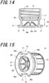
- a hole is formed in the thin-walled portion 38 that is formed around the center of the cover portion 29, and this hole is forcibly widened by the front end of the needle 70. Consequently, the cover portion 29 of the cap 17 is split along the groove portions 35a-35f as shown in FIGS. 14 and 15 . In other words, the cover portion 29 is broken into six parts along the groove portions 35a-35f.
- those portions which are formed with the groove portions 35a-35f are folded such that they can be wound upwardly. This leaves gaps 77 (see FIG. 15 ) around the needle stem 71 of the needle 70. One gap 77 is formed for each one of the groove portions 35a-35f. Because the cover portion 29 is split along the groove portions 35 and the cover portion 29 is folded partially so as to be wound upwardly, the gaps 77 are formed.
- the second surface 37 has the second groove portions 39 but the first surface 36 does not have the second groove portions 39. Therefore, if the user pushes the liquid container 11 in downwards, the hexagonal portion of the cover portion 29 which is surrounded by the second groove portions 39 is easily split along the groove portions 35. However, the hexagonal portion is held to the cap 17 as one part of the cover portion 29 and does not separate off as a fragment. Accordingly, when the cover portion 29 of the cap 17 is split along the groove portions 35 by a push of the needle 70, production of fragments can be suppressed.
- a space corresponding to a given distance 76 is secured inside the cap 17 to prevent fragments of the cover portion 29 created by splitting of it along the groove portions 35 from interfering or contacting with the sealing member 16.
- the distance 76 is not less than the length of the groove portions 35a-35f extending from the central portion of the cover portion 29. Consequently, the fragments of the cover portions 29 resulting from the splitting along the groove portions 35 do not hinder the open/close action of the sealing member 16 in response to insertion and removal of the needle 70.
- the open/close action of the sealing member 16 involves an operation by the needle 70 to force open the slitted portions 26a-26b formed in the sealing member 16 and an operation by the needle 70 to close the slitted portions 26a-26b as the needle is pulled out.
- the front end of the needle 70 breaks the cover portion 29 of the cap 17 along the groove portions 35, then comes into contact with the central portion of the sealing member 16, and pushes against the sealing member 16.
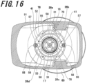
- the slitted portions 26a-26d formed in the sealing member 16 are pushed by the needle 70 and spread apart as shown in FIGS. 4 and 16 .
- the slitted portions 26a-26d spread apart form respective gaps 78 (see FIG. 16 ) around the needle stem 71 of the needle 70.
- Each one of the slitted portions 26a-26d forms one gap 78.
- FIG. 17 is a cross-sectional view showing the manner in which the liquid container 11 is set in the container holding portion 12 within the liquid feeder 10 of FIG. 1 .
- FIG. 18 is an enlarged view of a part of the liquid feeder 10 of FIG. 17 .
- the front end (top end) of the needle 70 juts up through both the cover portion 29 of the cap 17 and the sealing member 16. In this way, when the liquid container 11 is set in the container holding portion 12, the front end of the needle 70 enters into the port 21 of the container body 15. Therefore, the front end of the needle 70 touches the liquid (not shown) received in the liquid container 11.
- the cover portion 29 of the cap 17 is split along the groove portions 35, whereby the gaps 77 (see FIG. 15 ) are formed around the stem 71 of the needle 70.
- the slitted portions 26 in the sealing member 16 are spread apart, so that the gaps 78 (see FIG. 16 ) are formed.
- air passages 79 through the gaps 77 and 78 are formed inside the cap receiving portion 60 of the manifold 46. Air flows into the container body 15 through the passages 79. The liquid received in the container body 15 flows out of the container body 15 by its own weight. In particular, the liquid inside the container body 15 mainly passes through the two paths and flows out toward the reservoir 13 from the container body 15.
- the first exit path goes from the cutout holes 75 at the front end of the needle 70 through the hollow portion 74 of the needle 70.
- the second exit path goes through the gaps 77, 78 and through the communication holes 64.
- the liquid flowing out of the container body 15 through the first and second paths enters the reservoir 13 through the lower internal space of the manifold 46. As a result, the liquid flowing out of the container body 15 is accumulated in the reservoir 13.
- the liquid in the reservoir 13 is sent to the outside with a tube and a pump or the like. If the height of the surface of the liquid goes below the given height H, air enters into the container body 15 through the passages 79. Therefore, the liquid flows out from the container body 15 toward the reservoir 13. Such outflow of the liquid repeats whenever the liquid in the reservoir 13 is sent to the outside. Therefore, as long as the liquid remains in the container body 15, the height of the surface of the liquid is maintained at the given height H while the interior of the reservoir 13 is filled with the liquid.
- the above-described residual amount sensor (not shown) for detecting the remaining amount of the liquid in the reservoir 13 is mounted in it.
- the residual amount sensor is mounted in the sensor mounting hole 66 which is formed in the manifold 46 as described previously. If the amount of the liquid remaining in the reservoir 13 falls below a predetermined level, the residual amount sensor outputs a detection signal to that effect to the controller (not shown) of the automated analyzer. In response, the controller controls the display section such that a message prompting the user to exchange the container body 15 is displayed on the display screen of the display section of the analyzer.
- the controller displays information for identifying the liquid feeder 10 for which the amount of liquid remaining in the reservoir 13 is below the predetermined level, together with the message, on the display screen of the display section. Consequently, the user checks the information on the display screen of the display section, recognizes for which of the liquid feeders 10 is the amount of liquid remaining in the reservoir 13 below the predetermined level, and performs a work to replace the container body 15 based on the results of the recognition.
- a procedure performed by the user to implement the work to relace the liquid container 11 is described below.
- the user manually holds the grip portion 22 of the liquid container 11 set in the liquid feeder 10 for which the amount of liquid remaining in the reservoir 13 is below the predetermined level, and pulls up the liquid container 11 from the container holding portion 12.
- the needle 70 is pulled out of both the sealing member 16 and the cover portion 29 of the cap 17.
- the sealing member 16 is restored to its original shape (i.e., shape assumed before pushed by the needle 70) by the resilience of the sealing member 16.
- the slitted portions 26a-26d formed in the sealing member 16 return to their closed state as shown in FIG. 3 .
- the user sets an unused liquid container 11 in the container holding portion 12 according to a procedure similar to the foregoing procedure. As a consequence, the replacement of the liquid container 11 is completed.
- the liquid feeder 10 associated with the first embodiment of the present invention has: the sealing member 16 having the slitted portions 26a-26d; and the container body 15 having the cap 17 whose cover portion 29 is provided with the groove portions 35.
- the cover portion 29 of the cap 17 is so configured as to be split along the groove portions 35a-35f as the needle 70 pushes against the cover portion 29.
- the sealing member 16 is so configured that the slitted portions 26a-26d are spread apart as the needle 70 pushes against the sealing member 16. Consequently, inflow of air into the liquid container 11 and outflow of liquid from the liquid container 11 can be accomplished simply by providing the liquid container 11 with only one port 21.
- the number of ports formed in the liquid container can be reduced as compared with the conventional structure in which ports are formed in upper and lower portions, respectively, of a liquid container. Accordingly, where the container body 15 is fabricated by blow molding, for example, the fabrication of the container body 15 is facilitated and the fabrication cost can be lowered. Furthermore, the user does not need to loosen the threaded cap plugging up the top portion of the liquid container. This can alleviate the operational burden on the user.
- the sealing member 16 is provided with the plurality of slitted portions 26a-26d which extend radially outwardly from a central portion of the sealing member 16 and which are arranged rotationally symmetrically.
- the cover portion 29 of the cap 17 has the plurality of groove portions 35a-35f which extend radially outwardly from a central portion of the cover portion 29 and which are arranged rotationally symmetrically. Consequently, when the sealing member 16 is pushed by the needle 70, the slitted portions 26a-26d can be spread apart uniformly circumferentially of the sealing member 16. Furthermore, when the cover portion 29 of the cap 17 is pushed by the needle 70, the cover portion 29 can be split uniformly along the groove portions 35a-35f circumferentially of the cover portion 29.
- the cap 17 has the cylindrical sidewall 28 and the toroidal portion 30 protruding radially inwardly from the inner surface of the sidewall 28.
- the sealing member 16 is pushed against the end surface 21a of the port 21 by the toroidal portion 30. Consequently, simultaneously with the tightening of the cap 17, the sealing member 16 is brought into intimate contact with the end surface 21a of the port 21, whereby the opening of the port 21 can be sealed off by the sealing member 16.
- the flange portion 31 of the cap 17 is provided with the cutout portions 41 which define cutout positions corresponding to their respective types of liquid received in the container body 15.
- the container holding portion 12 has keys 56 and key mounting portions 55 to which the keys 56 are detachably mounted.
- the keys 56 are mounted at positions where mechanical interference with the flange portion 31 is avoided according to the types of liquid received in the container body 15.
- the key mounting portions 55 are so designed that the positions at which the keys 56 are mounted can be varied according to the types of liquid received in the container body 15. This can prevent incorrect insertion of the liquid container 11. Where plural liquid feeders 10 are mounted in the automated analyzer, the positions at which the keys 56 are mounted can be varied freely according to the types of liquid received in the container body 15 of each liquid feeder 10.
- the keys 56 are detachably mounted to the key mounting portions 55.
- the present invention is not restricted to this example.
- the keys 56 may be molded integrally with the container receiving portion 52.
- the front end of the needle 70 is shaped conically. Consequently, when the liquid container 11 is set in the container holding portion 12, the pushing force of the needle 70 can be concentrated on both the central portion of the cover portion 29 of the cap 17 and the central portion of the sealing member 16. Therefore, when the liquid container 11 is set in the container holding portion 12, the user can enter the front end side of the needle 70 into the port 21 through the cover portion 29 of the cap 17 and the sealing member 16 simply by pushing the liquid container 11 in downwards with a relatively small force.
- the needle 70 has a hollow portion 74.
- the cutout holes 75 in communication with the hollow portion 74 are formed around the front end of the needle 70. Consequently, where the front end side of the needle 70 is entered into the port 21 of the container body 15, the hollow portion 74 of the needle 70 can be used as one passage for the liquid flowing out from the container body 15 toward the reservoir 13.
- a liquid feeder associated with a second embodiment of the present invention is next described.
- This liquid feeder is similar to the above-described feeder associated with the first embodiment except for the needle structure.
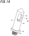
- FIG. 19 is a perspective view of the needle equipped in the liquid feeder associated with the second embodiment.
- FIG. 20 is a fragmentary cross-sectional view illustrating the arrangement of various portions of the liquid container of the liquid feeder of FIG. 19 when the container is set in the container holding portion.
- the needle, 80 has a needle stem 81, a needle jaw 82, and a needle base 83 which are formed integrally.
- the stem 81 of the needle 80 has a conical front end.
- the needle 80 has a hollow portion 84 which extends from the needle stem 81 to the needle base 83 along the central axis of the needle 80 through the needle jaw 82 except for the conical front end of the needle 80. That is, the needle 80 is hollow in structure.
- the structure of the needle 80 described so far is essentially identical to that of the needle 70 according to the first embodiment.
- Slots 85 in communication with the hollow portion 84 are formed in the needle stem 81 excluding the conical front end of the needle 80.
- the slots 85 are formed lengthwise in the peripheral wall of the needle stem 81.
- the slots 85 are two in number and formed in the single needle 80 and arranged at positions opposite to each other with respect to the central axis of the needle 80.
- the needle jaw 82 radially protrudes outwardly of both the needle stem 81 and the needle base 83.
- the needle base 83 is formed on the opposite side of the needle jaw 82 from the needle stem 81.
- the needle base 83 is formed on a rear end portion of the needle 80.
- the needle base 83 is inserted into the securing hole 63a of the needle mounting portion 63.
- the needle base 83 is externally threaded, for example, for a case where the needle 80 is tightened and screwed into the needle mounting portion 63 of the manifold 46.
- the needle 80 of the above-described structure is mounted to the needle mounting portion 63 of the manifold 46 as shown in FIG. 20 .
- the needle stem 81 of the needle 80 is raised vertically from the needle mounting portion 63 while the front end of the needle 80 faces upward.
- the stem 81 of the needle 80 is placed around the center of a space formed by the cap receiving portion 60 of the manifold 46.
- the cover portion 29 of the cap 17 is split along the groove portions 35a-35f as shown in FIG. 20 as the needle 80 pushes against the cover portion 29.
- the sealing member 16 is so configured that the slitted portions 26a-26d are spread apart as the needle 80 pushes against the sealing member 16, as can be seen from FIGS. 4 , 14 , 15 , 17 , 18 , and 20 . Therefore, the number of ports formed in the liquid container can be reduced in the same manner as in the first embodiment. Also, the operational burden on the user can be alleviated.
- the liquid feeder associated with the second embodiment of the present invention differs from the liquid feeder 10 associated with the first embodiment only as to the structure of the needle 80 and, therefore, yields the same advantageous effects as those of the first embodiment as well as the above-described advantageous effects.
- the front end of the needle 80 is shaped conically. This permits the user to bring the front end side of the needle 80 into the port 21 through both the cover portion 29 of the cap 17 and the sealing member 16 simply by pushing the liquid container 11 in downwards with a relatively small force, in the same manner as in the first embodiment described above.
- the needle 80 has the hollow portion 84, and the needle stem 81 excluding the conical front end of the needle 80 is provided with the slots 85 in communication with the hollow portion 84. Consequently, when the front end side of the needle 80 is entered into the port 21 of the container body 15, the hollow portion 84 of the needle 80 can be employed as one passage for the liquid flowing out from the container body 15 toward the reservoir 13.
- the front end of the needle 70 is shaped conically, and the conical surface of the needle 70 is provided with the cutout holes 75. Therefore, when the front end side of the needle 70 is entered into the port 21 of the container body 15, it is unlikely that parts of the sealing member 16 spread apart by the needle 70 will plug up the cutout holes 75. Also, when the needle 70 is pulled out of the cover portion 29 of the cap 17 in order to exchange the liquid container 11, it is unlikely that parts of the cover portion 29 split along the groove portions 35a-35f will become caught in the cutout holes 75. Accordingly, the structure of the needle 70 used in the first embodiment is preferably adopted as the needle structure.
- a liquid feeder associated with a third embodiment of the present invention is next described. This liquid feeder is similar to the liquid feeder associated with the first embodiment except for the structure of the cap.
- FIG. 21 is a perspective view of the cap 87 equipped in the liquid feeder associated with the third embodiment of the present invention, as viewed from the outside of the container body.
- FIG. 22 is a perspective view of the cap 87 of FIG. 21 as viewed from the inside of the container body.
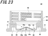
- FIG. 23 is a cross-sectional view of the cap 87 of FIGS. 21 and 22 .
- the cap 87 shown in FIGS. 21-23 is a member for securing the sealing member 16 to the port 21 of the container body 15.
- the cap 87 is made of a hard material such as a hard resin (e.g., polypropylene).
- the cap 87 has a cylindrical sidewall 88, a cover portion 89 closing off one opening of the sidewall 88, a toroidal portion 90 protruding radially inwardly from the inner surface of the sidewall 88, and a flange portion 91 protruding radially outwardly from the outer surface of the sidewall 88.
- the cap 87 is integrally molded from a resin.
- An internal thread 92 is formed on the inner side of the sidewall 88 together with the toroidal portion 90.
- the internal thread 92 meshes with the external thread 23 (see FIG. 2 ) on the port 21.
- the cap 87 is tightened and secured to the port 21 of the liquid container 11 by bringing the internal thread 92 into engagement with the external thread 23 on the port 21 and tightening the cap 87.
- the sealing member 16 is pushed against the end surface 21a of the port 21 by the help of the toroidal portion 90 by tightening the cap 87 as described previously.
- the port 21 is placed upward.
- the sealing member 16 is interposed between the end surface 21a of the port 21 and the toroidal portion 90 of the cap 87. Under this condition, the cap 87 is tightened. As a result, the sealing member 16 is intimately secured to the end surface 21a of the port 21.
- the cover portion 89 is disposed opposite to the sealing member 16 as shown in FIG. 24 .
- the cover portion 89 appears to be circular in shape when the cap 87 is viewed from its front side.
- a plurality of (four in the illustrated example) ribs 93 are formed around the cover portion 89 as shown in FIG. 21 and interconnect the sidewall 88 and the cover portion 89 radially of the cap 87.
- the cover portion 89 has a first surface 95 disposed opposite to the sealing member 16, a second surface 96 arranged on the opposite side of the first surface 95, and a tapering portion 97 in the form of a four-sided pyramid.
- the first surface 95 of the cover portion 89 acts as the inner surface of the cover portion 89 which faces into the interior of the container body 15, while the second surface 96 of the cover portion 89 serves as the outer surface of the cover portion 89 which faces toward the outside of the container body 15.
- the tapering portion 97 is so formed that its side facing the first surface 95 is convex, whereas its side facing the second surface 96 is concave.
- the tapering portion 97 of the cover portion 89 is provided with plural groove portions 98a-98d which are formed by partially reducing the thicknesswise dimension of the tapering portion 97 of the cover portion 89.
- the groove portions 98a-98d are so formed that when the needle 70 pushes against the cover portion 89, the cover portion 89 is split along the groove portions 98a-98d.
- FIGS. 21-23 show the structure of the cap 87 before the cover portion 89 is split along the groove portions 98a-98d.
- four groove portions 98a-98d are formed in the tapering portion 97 of the cover portion 89 as one example.
- the four groove portions 98a-98d are arranged rotationally symmetrically and extend radially outwardly from a central portion of the cover portion 89.
- the four groove portions 98a-98d are formed in both first surface 95 and second surface 96. More specifically, the four groove portions 98a-98d extend along the ridge line of the tapering portion 97 the side of which facing the first surface 95 is convex. The groove portions 98a-98d also extend along the ridge line of the tapering portion 97 the side of which facing the second surface 96 is concave. In other words, the four groove portions 98a-98d are formed at their respective corresponding positions in the first surface 95 and second surface 96.
- the depthwise dimension of the groove portions 98a-98d on the side of the first surface 95 is identical to that of the groove portions 98a-98d on the side of the second surface 96 but may be different from that.
- Thin-walled portions 99 are formed in a central portion of the tapering portion 97 to suppress positional deviations of the needle 70.
- the thin-walled portions 99 are formed in both the first surface 95 and the second surface 96 in the same way as for the four groove portions 98a-98d described above.
- the thin-walled portions 99 are shaped nearly circularly.
- the thicknesswise dimension of the thin-walled portion 99 on the side of the first surface 95 is identical to that of the groove portions 98a-98d on the side of the first surface 95.
- the thicknesswise dimension of the thin-walled portion 99 on the side of the second surface 96 is identical to that of the groove portions 98a-98d on the side of the second surface 96.
- the flange portion 91 is provided with a plurality of cutout portions 100.
- two cutout portions 100 are formed circumferentially of the flange portion 91 as one example.
- the two cutout portions 100 are angularly spaced 180° from each other circumferentially of the cap 87.
- the cutout portions 100 have a given circumferential width. Cutout positions respectively defined by the cutout portions 100 circumferentially of the cap 87 are determined according to types of liquid received in the container body 15.
- the number of the cutout portions 100 may be either one or three or more.
- the cutout portions 100 in the flange portion 91 are formed to prevent incorrect insertion of the liquid container 11.
- the principle of preventing incorrect insertion of the liquid container 11 is the same as the principle adopted in the above-described first embodiment and so a description thereof is omitted herein.
- a positional deviation S may occur between the central axis of the cap 87 and the central axis of the needle 70 as shown in FIG. 24 .
- the positional deviation S can be suppressed by enhancing the positioning accuracy of the container body 15 with respect to the case portion 51 when the container body 15 of the liquid container 11 is inserted into the case portion 51 of the container holding portion 12.
- enhancing the positioning accuracy of the container body 15 with respect to the case portion 51 makes it more difficult to insert the container body 15 into the case portion 51.
- enhancing the positional accuracy increases the costs of manufacturing the liquid container 11, cap 87, and case portion 51. Therefore, in order to permit the container body 15 to be smoothly inserted into the case portion 51 and to suppress increases in the costs of fabricating the liquid container 11, cap 87, and case portion 51, it is necessary to lessen the above-described positional accuracy.
- a tapering portion 97 is formed in the cover portion 89 of the cap 87. Groove portions 98a-98d are formed in the tapering portion 97. Therefore, if the positional deviation S occurs between the central axis of the cap 87 and the central axis of the needle 70, the tilted surface of the tapering portion 97 comes into contact with the front end of the needle 70. At this time, the tilted surface of the tapering portion 97 acts as a guide surface which guides the front end of the needle 70 toward a central portion (thin-walled portions 99) of the tapering portion 97.
- the front end of the needle 70 comes into contact with the tilted surface or recess of the tapering portion 97 while the container body 15 is being inserted into the case portion 51 by the user, a lateral or horizontal force F is applied to the cap 87, thus reducing the positional deviation S.
- the cap 87 is mounted to the port 21 of the container body 15. Therefore, if the lateral force F is applied to the cap 87, the container body 15 is positionally corrected together with the cap 87.
- the positional deviation S is eliminated. Consequently, the front end of the needle 70 can be brought into contact with a central portion of the cover portion 89.
- the cover portion 89 of the cap 87 is pushed by the needle 80, whereby the cover portion 89 is broken along the groove portions 98a-98d.
- the central portion of the cover portion 89 is pushed by the front end of the needle 80, holes are created in the thin-walled portions 99 in the central portion of the cover portion 89 and spread apart by the front end of the needle 80.
- the tapering portion 97 of the cover portion 89 is broken into four parts along the groove portions 98a-98d.
- the positioning accuracy of the container body 15 with respect to the case portion 51 is loosened, it is assured that the front end of the needle 80 is brought into contact with the central portion of the cover portion 89 and that the tapering portion 97 of the cover portion 89 can be broken along the groove portions 98a-98d.
- the tilted surface of the tapering portion 97 functions as a guide surface for guiding the front end of the needle 80 to the central portion of the cover portion 89. This can maintain constant the user's push-in force needed to break the tapering portion 97 of the cover portion 89 along the groove portions 98a-98d. Consequently, it is possible to offer a user-friendly liquid feeder.
- the tapering portion 97 of the cover portion 89 is shaped in the form of a four-sided pyramid.
- the present invention is not restricted to this example.
- the tapering portion of the cover portion 89 may also be a polygonal pyramid other than a four-sided pyramid.
- a conical shape is also available.
- the number of groove portions 98 formed in the tapering portion of the cover portion 89 may be varied according to the shape of the tapering portion.
- the liquid feeder associated with the third embodiment of the present invention may be equipped with the needle 80 instead of the needle 70.
- each needle has a hollow structure as a preferred example.
- the present invention is not restricted to this example.
- the needle may have no hollow portion.
- the front end of the needle is shaped conically as a preferred example.
- the present invention is not restricted to this example.
- the front end of the needle may be in a pyramidal form.
- the cover portion 29 can be split along the groove portions 35 when the cover portion 29 of the cap 17 is pushed by the front end of the needle, the front end of the needle may be shaped in any form.
- the groove portions 35 are formed in both the first surface 36 and the second surface 37 of the cover portion 29 of the cap 17 as a preferred example.
- the present invention is not restricted to this example.
- the groove portions 35 may be formed only in one surface of the cover portion 29 of the cap 17.
- the same principle applies to the above-described third embodiment, i.e., the groove portions 98 formed in the tapering portion 97 of the cover portion 89.
Landscapes
- Chemical & Material Sciences (AREA)
- Health & Medical Sciences (AREA)
- Immunology (AREA)
- Pathology (AREA)
- Analytical Chemistry (AREA)
- Biochemistry (AREA)
- General Health & Medical Sciences (AREA)
- General Physics & Mathematics (AREA)
- Physics & Mathematics (AREA)
- Life Sciences & Earth Sciences (AREA)
- Clinical Laboratory Science (AREA)
- Chemical Kinetics & Catalysis (AREA)
- Engineering & Computer Science (AREA)
- Mechanical Engineering (AREA)
- Medicinal Chemistry (AREA)
- Closures For Containers (AREA)
- Automatic Analysis And Handling Materials Therefor (AREA)
Abstract
There is provided a liquid feeder (10) using a liquid container (11) having a reduced number of ports than conventional. The liquid feeder (10) can reduce the operational burden on the user. The liquid feeder (10) comprises the liquid container (11) and a container holding portion (12) that holds the liquid container (11). The liquid container (10) has a container body (15), a sealing member (16), and a cap (17). The container holding portion (12) has a cap receiving portion (60) and a needle (70). The sealing member (16) is made of a resilient material and has slitted portions (26). The cap (17) is made of a hard material and has a cover portion (29) that is disposed opposite to the sealing member (16). The cover portion (29) is so configured as to be split along groove portions (35) when the needle (70) pushes against the cover portion (29). The slitted portions (26) of the sealing member (16) are spread apart when the needle (70) pushes against the sealing member (16).
Description
- The present invention relates to a liquid feeder for use in an automated analyzer.
- An automated analyzer is an instrument for quickly and accurately analyzing multiple components contained in an analyte, and is used in various fields including biochemical examinations and blood transfusion examinations. Furthermore, an automated analyzer is equipped with a measuring section for measuring analytes. In the measuring section, liquids such as diluents and cleaning liquids are used. These liquids are stored in reservoirs equipped in the automated analyzer. The liquids stored in the reservoirs are fed into given sections using pumps and tubes, for example.
- If a liquid stored in a reservoir is fed into a given section using a pump or the like, the amount of the remaining liquid decreases accordingly. Therefore, the reservoir needs to be refilled with the liquid before the reservoir is emptied. Consequently, the automated analyzer has a liquid feeder for feeding the liquid into the reservoir.
- With respect to such liquid feeders, a technique set forth, for example, in patent document 1 is known. This patent document 1 discloses a configuration having ports formed in an upper portion and a lower portion, respectively, of a liquid container. A threaded cap is attached to the upper port. A septum and the cap are attached to the lower port. Patent document 1 also discloses a configuration using a mounting bracket in which a liquid container is set. A needle is mounted at the bottom of the bracket and operative to pierce the septum.
- Patent document 1:
Japanese Patent No. 4,945,572 - In the technique set forth in patent document 1, however, the two ports are formed in the liquid container. Therefore, if the liquid container is fabricated by blow molding, for example, the fabrication is made more difficult. Also, the cost of fabrication of the liquid container increases. Furthermore, with the technique set forth in patent document 1, when the needle pierces the septum, the user needs to loosen the threaded cap plugging up the upper port in order to cause air to flow into the liquid container so that the liquid inside the liquid container flows down through the needle. Therefore, in view of the user's operability, there is a problem to be remedied.
- The present invention has been made to solve the above-described problem. It is an object of the present invention to provide a liquid feeder which can reduce the number of ports formed in a liquid container and which can alleviate the burden imposed on the user's operability.
- A liquid feeder associated with the present invention comprises: a liquid container having (i) a container body provided with a port and operative to receive a liquid, (ii) a sealing member for sealing the port of the container body, and (iii) a cap for securing the sealing member to the port; and a container holding portion for holding the liquid container while the cap is placed downward. The container holding portion has: a cap receiving portion that forms a space capable of accepting the cap; and a needle disposed in the space formed by the cap receiving portion. The sealing member is made of a resilient material and has slitted portions. The cap is made of a hard material and has a cover portion disposed opposite to the sealing member. The cover portion has groove portions formed by partially reducing the cover portion in thickness. The cover portion of the cap is so configured as to be split along the groove portions when the needle pushes against the cover portion. The sealing member is so configured that the slitted portions are spread apart when the needle pushes against the sealing member.
- According to the present invention, the number of ports formed in the liquid container can be reduced. Also, the burden on the user's manipulation can be alleviated.
-
-
FIG. 1 is a cross-sectional view of a liquid feeder associated with a first embodiment of the present invention, showing the configuration of the feeder. -
FIG. 2 is an enlarged view of a portion of the liquid feeder ofFIG. 1 . -
FIG. 3 is a perspective view of a sealing member equipped in the liquid feeder ofFIG. 1 , showing the configuration of the sealing member. -
FIG. 4 is a perspective view similar toFIG. 3 , but in which slitted portions of the sealing member have been spread out. -
FIG. 5 is a perspective view of a cap equipped in the liquid feeder ofFIG. 1 as viewed from the outside of the container body. -
FIG. 6 is a perspective view similar toFIG. 5 , but as viewed from the inside of the container body. -
FIG. 7 is a plan view of the cap of the liquid feeder ofFIG. 1 . -
FIG. 8 is a cross-sectional view of the cap ofFIG. 7 , as taken along line A-A. -
FIG. 9 is an enlarged view of portion B ofFIG. 8 . -
FIG. 10 is a cross-sectional view of the liquid feeder ofFIG. 1 , as taken along line C-C. -
FIG. 11 is a perspective view of a manifold shown inFIG. 1 . -
FIG. 12 is a plan view of the needle ofFIGS. 1 and2 . -
FIG. 13 is a perspective view of the needle ofFIG. 12 . -
FIGS. 14 and 15 are a cross-sectional view and a perspective view, respectively, showing the manner in which the cover portion of the cap has been split along the groove portions. -
FIG. 16 is a cross-sectional view illustrating the manner in which the slitted portions of the sealing member have been pushed and spread out by the needle. -
FIG. 17 is a cross-sectional view showing the manner in which the liquid container of the liquid feeder ofFIG. 1 has been set in the container holding portion. -
FIG. 18 is an enlarged view of a portion of the liquid feeder shown inFIG. 17 . -
FIG. 19 is a perspective view of a needle equipped in a liquid feeder associated with a second embodiment of the present invention. -
FIG. 20 is a partial cross-section illustrating the arrangement of various portions of the liquid feeder ofFIG. 19 when the liquid container is set in the container holding portion. -
FIG. 21 is a perspective view of a cap equipped in a liquid feeder associated with a third embodiment of the invention, as viewed from the outside of the container body. -
FIG. 22 is a perspective view of the cap similar toFIG. 21 , but as viewed from the inside of the container body. -
FIG. 23 is a cross-sectional view of the cap of the liquid feeder ofFIGS. 21 and 22 . -
FIG. 24 is a partial cross-section showing the manner in which there is a positional deviation between the central axis of the cap and the central axis of the needle when a user sets a liquid container in the container holding portion. - The preferred embodiments of the present invention are hereinafter described in detail with reference to the drawings. In the present specification and drawings, elements having the same function or configuration are indicated by the same reference numerals and repetitive description thereof is omitted. Furthermore, it is to be understood that the following description and drawings are merely exemplary and that they may be simplified or omitted for the sake of illustration. Each component of the invention may be either singular or plural unless specifically stated otherwise. In addition, the position, size, shape, and range of each component in the drawings may not precisely represent the actual position, size, shape, and range for ease of understanding of the present invention. Therefore, the present invention is not always restricted to the positions, sizes, shapes, ranges, and so on disclosed in the drawings.
-
FIG. 1 is a cross-sectional view showing the configuration of a liquid feeder, 10, associated with a first embodiment of the present invention.FIG. 2 is an enlarged view of a portion of theliquid feeder 10 ofFIG. 1 . InFIG. 1 , the up/down direction is parallel to a vertical direction, and the left/right direction is parallel to a horizontal direction. - As shown in
FIGS. 1 and2 , theliquid feeder 10 includes aliquid container 11, acontainer holding portion 12 for holding theliquid container 11, and aliquid reservoir 13 for storing the liquid flowing downward from theliquid container 11. Theliquid feeder 10 is equipped, for example, in an automated analyzer that uses liquids such as various diluents and cleaning liquids. Theliquid feeder 10 may also be an instrument other than an automated analyzer, and may be equipped in various instruments handling different kinds of liquid. In the present embodiment, it is assumed that theliquid feeder 10 is equipped in an automated analyzer. As mentioned previously, an automated analyzer is an instrument for quickly and accurately analyzing multiple components contained in an analyte, and is used in various fields including biochemical examinations and blood transfusion examinations. Generally, a single automated analyzer is equipped with a plurality ofliquid feeders 10. Also, of the components of eachliquid feeder 10, theliquid container 11 is replaceable, and thecontainer holding portion 12 andreservoir 13 are always in position within theliquid feeder 10. - The
liquid container 11 is detachably mounted to thecontainer holding portion 12. When theliquid container 11 is set in thecontainer holding portion 12, thecontainer 11 is inserted from above to below into thecontainer holding portion 12. When theliquid container 11 is taken out of thecontainer holding portion 12, thecontainer 11 is pulled up from thecontainer holding portion 12. The work of mounting or detaching theliquid container 11 to or from thecontainer holding portion 12 is done by a user.FIGS. 1 and2 show a state in which theliquid container 11 is being inserted into thecontainer holding portion 12 to set thecontainer 11 in the holdingportion 12. - The
liquid container 11 has acontainer body 15, a sealingmember 16, and acap 17. Thecontainer body 15 is made of a bottle that accommodates a liquid. The bottle acting as thecontainer body 15 is treated, for example, as a disposable or replaceable bottle. In this case, the sealingmember 16 and thecap 17 are treated as disposable members in the same manner as the above-described replaceable bottle. Note that thecontainer body 15 may not be disposable but rather made reusable by cleaning or otherwise processing it. The bottle serving as thecontainer body 15 is fabricated by blow molding, for example. Thecontainer body 15 is a hollow body having a capacity to receive a given amount of liquid. - The
container body 15 has aport 21 and a grip portion 22 (seeFIG. 1 ) which are integral with each other. When theliquid container 11 is set in thecontainer holding portion 12, thebody port 21 is disposed downward. Theport 21 is shaped cylindrically. An external thread 23 (seeFIG. 2 ) is formed on the outer surface of thebody port 21. Thegrip portion 22 is disposed on the opposite side of thebody port 21 as viewed in the up/down direction inFIG. 1 . When theliquid container 11 is set in thecontainer holding portion 12, the user manually holds thegrip portion 22 to carry thecontainer 11. A tab 24 (seeFIG. 1 ) is formed integrally with theliquid container 11 to make it possible to detect whether theliquid container 11 has been set in thecontainer holding portion 12, i.e., a sensor (not shown) detects the presence or absence of theliquid container 11. - In the present example, the
tab 24 is mounted to theliquid container 11 but the present invention is not restricted to this example. For example, it may be detected as to whether theliquid container 11 has been set in thecontainer holding portion 12 via a separate member. When theliquid container 11 is set in acase portion 51 of thecontainer holding portion 12 which will be described later, a rotatable member comes into contact with theliquid container 11 and rotates. A sensor detects the rotation of this rotatable member, whereby detecting whether theliquid container 11 has been set in thecontainer holding portion 12. The sensor may be an optical sensor consisting of a light emitter emitting light and a light receiver detecting the light from the light emitter. When theliquid container 11 is set and the rotatable member rotates, this rotating member blocks the light from the light emitter. Consequently, it is possible to detect that theliquid container 11 has been set in thecontainer holding portion 12. The rotatable member is preferably an opaque member that does not transmit light. - The sealing
member 16 serves to seal off theport 21 of theliquid container 11 and is made of a resilient material such as a synthetic resin. That is, the sealingmember 16 is a rubberlike resilient body. The sealingmember 16 is placed in intimate contact with anend surface 21a (seeFIG. 2 ) of thebody port 21. -
FIG. 3 is a perspective view showing the configuration of the sealingmember 16 of the liquid feeder associated with the first embodiment of the present invention. As shown, the sealingmember 16 is shaped in the form of a circular disk having a given thickness. The sealingmember 16 is provided withslitted portions 26 which extend thicknesswise through the sealingmember 16. The surfaces forming theslitted portions 26a-26d are kept in intimate contact with each other by the resilience of the sealingmember 16. - The
slitted portions 26a-26d in the sealingmember 16 extend radially outwardly from a central portion of the sealingmember 16. In the present embodiment, fourslitted portions 26a-26d are formed as an example in the sealingmember 16 and arranged rotationally symmetrically and in a crisscross manner. - The sealing
member 16 is so configured that a needle 70 (seeFIGS. 1 and2 ) pushes against the sealingmember 16 to thereby spread theslitted portions 26a-26d apart as shown inFIG. 4 . The sealingmember 16 is also configured so that, when theneedle 70 is pulled out of the sealingmember 16, the resilience of the sealingmember 16 closes theslitted portions 26a-26d. The structure of theneedle 70 is described in further detail later. - Assuming that the sealing
member 16 has a thickness of t in mm, the thickness t of the sealingmember 16 is preferably between 3 mm and 7 mm as shown inFIG. 3 . Assuming that theneedle 70 has a radius of r in mm, the length L in mm of each of theslitted portions 26a-26d preferably satisfies Eq. (1) below. The radius r of theneedle 70 is the radius of thestem 71 of theneedle 70 shown inFIGS. 12 and 13 .
- If the length L of each of the
slitted portions 26a-26d satisfies Eq. (1) above, the following advantages arise. When the fourslitted portions 26a-26d are spread apart by theneedle 70, given gaps can be formed between successive ones of theslitted portions 26a-26d. The gaps are formed around theneedle 70 because each of theslitted portions 26a-26d is spread apart into a V-shaped form as viewed along the central axis of theneedle 70. The given gaps between the successive ones of theslitted portions 26a-26d can be used as air and fluid passages. When theneedle 70 is pulled out of the sealingmember 16, the resilience of the sealingmember 16 restores theslitted portions 26a-26d into their original state, i.e., before spread apart by theneedle 70, and closes the given gaps. Therefore, when theneedle 70 is pulled out of the sealingmember 16, leakage of liquid from theslitted portions 26a-26d can be suppressed. - In the present embodiment, the four
slitted portions 26a-26d are formed in the sealingmember 16 and arranged in a crisscross fashion. The present invention is not restricted to this example. For example, three slitted portions may be formed in the sealingmember 16 so as to be circumferentially equally spaced from each other about a central portion of the sealingmember 16. In addition, the sealingmember 16 may be provided with five or more slitted portions. - Furthermore, in the present embodiment, the four
slitted portions 26a-26d extend thicknesswise through the sealingmember 16. The present invention is not restricted to this example. For example, theslitted portions 26a-26d may depthwise extend not fully through the sealingmember 16 such that thin-walled portions are left in the deepest portions of theslitted portions 26a-26d. In this case, the performance of the sealingmember 16 in terms of sealing theport 21 during transportation or storage of theliquid container 11 can be enhanced. When the needle 70 (seeFIGS. 1 and2 ) pushes against the sealingmember 16, the thin-walled portions are pushed and broken by theneedle 70. Therefore, theslitted portions 26a-26d can be pushed and spread out by theneedle 70. - The
cap 17 is a member mounted to theport 21 of thecontainer body 15 in order to attach the sealingmember 16 to theport 21. Thecap 17 is made of a hard material such as a hard resin (e.g., polypropylene). -
FIG. 5 is a perspective view of thecap 17 equipped in the liquid feeder associated with the first embodiment of the present invention, as viewed from the outside of the container body 15 (i.e., from the underside ofFIG. 1 ).FIG. 6 is a perspective view of thecap 17 ofFIG. 1 , as viewed from the inside of the container body 15 (i.e., from the top side ofFIG. 1 ).FIG. 7 is a plan view of thecap 17 of the liquid feeder ofFIG. 1 .FIG. 8 is a cross-sectional view of thecap 17 ofFIG. 7 , taken on line A-A.FIG. 9 is an enlarged view of portion B ofFIG. 8 . - As shown in
FIGS. 5-9 , thecap 17 has acylindrical sidewall 28, acover portion 29 closing off one opening of thesidewall 28, atoroidal portion 30 radially inwardly protruding from the inner side surface of thesidewall 28, and aflange portion 31 protruding radially outwardly of the outer surface of thesidewall 28. Thecap 17 is unitarily molded from a resin. - On the inner side of the
sidewall 28, aninternal thread 32 is formed together with thetoroidal portion 30. When thecap 17 is mounted to theport 21 of thecontainer body 15, theinternal thread 32 engages theexternal thread 23 on theport 21. By bringing theinternal thread 32 into engagement with theexternal thread 23 on theport 21 as shown inFIG. 2 and tightening thecap 17, thecap 17 is clampingly secured against theport 21 of theliquid container 11. As described previously, thetoroidal portion 30 pushes the sealingmember 16 against theend surface 21a of theport 21 by tightening thecap 17. When thecap 17 is mounted to theport 21 of thecontainer body 15, theport 21 is placed upward. In this case, the sealingmember 16 is disposed between theend surface 21a of theport 21 and thetoroidal portion 30 of thecap 17. Under this condition, thecap 17 is tightened, whereby the sealingmember 16 is secured to theend surface 21a of theport 21 while in intimate contact with it. - The
cover portion 29 is disposed opposite to the sealingmember 16 as shown inFIG. 2 . When thecap 17 is viewed from the front side, thecover portion 29 appears to be circular in shape. Thecover portion 29 is shaped in a disklike form. When thecap 17 has been attached to theport 21, thecover portion 29 is placed a given distance (described later) from the sealingmember 16. -
Groove portions 35 are formed in thecover portion 29 by partially reducing the thicknesswise dimension of thecover portion 29. Therefore, the parts of thecover portion 29 which have thegroove portions 35 provide lower mechanical strength than the other parts. However, thecover portion 29, including the parts where thegroove portions 35 are formed, has no through-holes extending thicknesswise. Therefore, when theport 21 of thecontainer body 15 is sealed by the sealingmember 16 and tightened by thecap 17, it follows that theport 21 is sealed doubly by the sealingmember 16 and thecap 17. This can enhance the sealability of theliquid container 11 during transportation or storage. - The
cover portion 29 has the plural groove portions 35 (35a-35f) extending radially outwardly from a central portion of thecover portion 29. The groove portions 35 (35a-35f) are so formed that when theneedle 70 pushes against thecover portion 29, thecover portion 29 is split along thegroove portions 35a-35f. In the present embodiment, 6groove portions 35a-35f are formed in thecover portion 29 as an example. The 6groove portions 35a-35f are formed rotationally symmetrically and arranged radially. Preferably, each of thegroove portions 35a-35f has a V-shaped cross-sectional shape. They may also have other cross-sectional shape, such as a U-shaped cross-sectional shape. - The
cover portion 29 has a first surface 36 (seeFIGS. 6 and8 ) and a second surface 37 (seeFIGS. 5and 8 ) which are disposed on opposite sides of each other, thefirst surface 36 being opposite to the sealingmember 16. When thecap 17 has been mounted to theport 21 of thecontainer body 15, thefirst surface 36 of thecover portion 29 acts as the inner surface of thecover portion 29 that faces into thecontainer body 15 while thesecond surface 37 of thecover portion 29 serves as the outer surface of thecover portion 29 that faces outside of thecontainer body 15. - On the other hand, the six
groove portions 35a-35f are formed in bothfirst surface 36 andsecond surface 37. Thegroove portions 35a-35f in thefirst surface 36 have the same depth as thegroove portions 35a-35f in thesecond surface 37. Note that the depth of thegroove portions 35a-37f in thefirst surface 36 may be different from the depth of thegroove portions 35a-35f in thesecond surface 37. The 6groove portions 35a-35f are formed at their respective corresponding positions in thefirst surface 36 and thesecond surface 37. That is, if thecap 17 is seen through from the front side, they would be in registry with each other. - Thin-walled portions 38 (see
FIGS. 5 and 6 ) are formed in the central portion of thecover portion 29 to suppress positional deviations of theneedle 70. The thin-walled portions 38 are formed in bothfirst surface 36 andsecond surface 37 in the same way as the above-described 6groove portions 35a-35f. The thin-walled portions 38 are shaped substantially circularly. The depth of the thin-walled portions 38 in thefirst surface 36 is the same as that of thegroove portions 35a-35f in thefirst surface 36. The depth of the thin-walled portions 38 in thesecond surface 37 is the same as that of thegroove portions 35a-35f in thesecond surface 37. -
Second groove portions 39 are formed in thesecond surface 37 of thecover portion 29 as shown inFIG. 5 . In contrast, thesecond groove portions 39 are not formed in thefirst surface 36 of thecover portion 29 as shown inFIG. 6 . When theneedle 70 pushes against thecover portion 29, thesecond groove portions 39 facilitate splitting of thecover portion 29 along thegroove portions 35a-35f and prevent fragments of thesplit cover portion 29 from separating from thecap 17. - The
second groove portions 39 in thesecond surface 37 have the same depth as that of thegroove portions 35a-35f in thesecond surface 37. Thesecond surface 37 is so formed as to interconnect the radially outer ends of thegroove portions 35a-35f formed in thesecond surface 37. In the present embodiment, the sixgroove portions 35a-35f are formed in thesecond surface 37. The overall arrangement of thesecond groove portions 39 is hexagonal in shape as viewed from the front of thecap 17. The shape of the overall arrangement of thesecond groove portions 39 is not restricted to a hexagon but rather may be a polygon corresponding to the number of groove portions formed in thesecond surface 37. If four groove portions, for example, are formed in thesecond surface 37 in a crisscross manner, the overall arrangement of thesecond groove portions 39 is shaped tetragonally in a manner not illustrated. Furthermore, thesecond groove portions 39 may be circular in shape regardless of the number of groove portions formed in thesecond surface 37. -
Plural cutout portions 41 are formed in theflange portion 31. In the present embodiment, twocutout portions 41 are formed on the circumference of theflange portion 31 as an example. The twocutout portions 41 are spaced 180° from each other circumferentially of thecap 17. Thecutout portions 41 have a given circumferential width. The positions of thecutout portions 41, i.e., slit positions, as taken circumferentially of thecap 17 are determined according to the type of liquid received in thecontainer body 15. The number of thecutout portions 41 may be either one or three or more. Where thecap 17 is threadedly tightened and secured to theport 21 of thecontainer body 15, the positions of thecutout portions 41 as taken circumferentially of thecap 17 can be brought to preliminarily assumed positions by either causing a portion of thecap 17 to strike theend surface 21a (seeFIG. 2 ) of theport 21 or controlling the tightening torque on thecap 17. - The
cutout portions 41 in theflange portion 31 are formed to prevent incorrect insertion of anyliquid container 11 that is different from theliquid container 11 to be inserted and set in thecontainer holding portion 12. In particular, there is presented a case where there are oneliquid container 11 for receiving a first diluting fluid and anotherliquid container 11 for receiving a second diluting fluid different in type (such as components) from the first diluting fluid. In this case, it is probable that theliquid container 11 receiving the first diluting fluid should be inserted in thecontainer holding portion 12 but the user might incorrectly insert theliquid container 11 receiving the second diluting fluid. Such incorrect insertion of theliquid container 11 is prevented by mechanical interference between theflange portion 31 and keys 56 (described later) (seeFIG. 10 ). - The
container holding portion 12 holds theliquid container 11 while thecap 17 is placed downward. As shown inFIGS. 1 and2 , thecontainer holding portion 12 has ahousing 45 and a manifold 46. The manifold 46 is tightened and secured to the bottom or a lower portion of thehousing 45 with a plurality ofbolts 47. A ring-shaped sealingmember 48 is mounted inside the tightening positions of thebolts 47 and suppresses leakage of gas and liquid at the contact interface between thehousing 45 and the manifold 46. - The
housing 45 has sufficient rigidity to hold thecontainer body 15 in which a given amount of liquid is received. Thehousing 45 has the above-describedcase portion 51 forming a space capable of receiving thecontainer body 15, acontainer receiving portion 52 formed at the bottom of thecase portion 51, and aconnector portion 53 connected to themanifold 46. All of these portions 51-53 are formed integrally. - The
liquid container 11 which is inserted and set in thecontainer holding portion 12 is received and supported from below by thecontainer receiving portion 52. In particular, the bottom surface of thecontainer body 15 is received and supported from below outside of thebody port 21 by thecontainer receiving portion 52. As a result, the whole mass of theliquid container 11 including the mass of the liquid received in thecontainer body 15 acts on thecontainer receiving portion 52. - As shown in
FIG. 10 , thecontainer receiving portion 52 is formed in a toroidal shape.FIG. 10 is a cross-sectional view of theliquid feeder 10 ofFIG. 1 , taken on line C-C. A plurality of key mountingportions 55 are formed on the same circumferential surface as thecontainer receiving portion 52. Onekey 56 is detachably attached to each key mountingportion 55. Thekeys 56 prevent incorrect insertion of theliquid container 11. Thekeys 56 are mounted at positions where mechanical interference with theflange portion 31 is prevented according to the type of liquid received in thecontainer body 15. Thekey mounting portions 55, thekeys 56, and thecontainer receiving portion 52 together constitute thehousing 45 of thecontainer holding portion 12. - The
key mounting portions 55 are formed by partly recessing the above-described circumferential surface. In the present embodiment, six key mountingportions 55 are formed as an example. The 6key mounting portions 55 are circumferentially equally spaced from each other at intervals of 60°. Also in the present embodiment, onekey 56 is attached to two ones of the 6key mounting portions 55. The number ofkeys 56 is equal to the number of thecutout portions 41 formed in theflange portion 31 of thecap 17. Each key 56 is mounted to the key mountingportions 55 withbolts 57. Therefore, each key mountingportion 55 has a threadedhole 58 engaging with an external thread on eachbolt 57. The dimension of the recess of each key mountingportion 55 is so set that, when the key 56 is attached to thekey mounting portion 55 with thebolt 57, the head of thebolt 57 is lower than the top surface of thecontainer receiving portion 52. The key 56 protrudes radially inwardly of thecontainer receiving portion 52. The dimension of the protrusion of the key 56 is so set that, if anyliquid container 11 is incorrectly inserted, the key 56 will contact theflange portion 31 of thecap 17, thus mechanically interfering with it. - The
connector portion 53 is formed radially outwardly of thecontainer receiving portion 52 as shown inFIG. 2 . Theconnector portion 53 is formed in a toroidal shape and has an internal thread which mates with the external thread on thebolt 47. Thehousing 45 and the manifold 46 are fastened together by tightening thebolts 47 mating with the threaded holes in theconnector portion 53. -
FIG. 11 shows the manifold 46 as viewed obliquely from above. As shown, the manifold 46 is an integral, hollow member having acap receiving portion 60, a first mountingportion 61, a second mountingportion 62, and aneedle mounting portion 63. Thecap receiving portion 60 is shaped cylindrically and forms a space capable of receiving thecap 17. The needle 70 (seeFIG. 2 ) is disposed in the inside space of thecap receiving portion 60. Theneedle 70 cooperates with thehousing 45 and the manifold 46 to constitute thecontainer holding portion 12. Thecap receiving portion 60 has an upper end portion fitted inside theconnector portion 53. - The first mounting
portion 61 is used to mount the manifold 46 to thehousing 45. The first mountingportion 61 is provided with through-holes 61a into which the external threads of thebolts 47 are inserted. In the present embodiment, four through-holes 61a are formed in the first mountingportion 61 as an example. In this case, the manifold 46 is tightened and secured to theconnector portion 53 of thehousing 45 with the fourbolts 47. - The second mounting
portion 62 is used to mount the manifold 46 to thereservoir 13. Thereservoir 13 has an upper end portion to which the second mountingportion 62 is fastened with afixture 65 that uses a tightening force, for example, produced by mating between threads. - The
needle mounting portion 63 is used to mount theneedle 70 to the manifold 46 having an internal space that is partitioned into an upper space higher than theneedle mounting portion 63 and a lower space lower than theneedle mounting portion 63. A plurality of communication holes 64 are formed around theneedle mounting portion 63 to place the upper and lower spaces inside the manifold 46 into communication with each other. In the present embodiment, fourcommunication holes 64 are formed around theneedle mounting portion 63 as an example. - A securing
hole 63a is formed in theneedle mounting portion 63 to secure theneedle 70. Where theneedle 70 is tightened and secured to theneedle mounting portion 63, for example, by mating between threads, the securinghole 63 is an internally threaded hole. In this case, an external thread mating with the securinghole 63 is formed on theneedle 70. The means for securing theneedle 70 to theneedle mounting portion 63 is not restricted to tightening using threads. Other means such adhesive bonding or press fitting is also available. - The manifold 46 is provided with a
sensor mounting hole 66 in which a residual amount sensor (described later) (not shown) is mounted. -
FIG. 12 is a plan view of the needle equipped in the liquid feeder ofFIG. 1 as viewed from the front side.FIG. 13 is a perspective view of this needle. As shown in theseFIGS. 12 and 13 , theneedle 70 has aneedle stem 71, aneedle jaw 72, and aneedle base 73 which are formed integrally. Preferably, theneedle 70 is made of a chemical-resistant metal. The front end of thestem 71 of theneedle 70 is placed upward. Theneedle 70 has a conical front end. - The
needle 70 has ahollow portion 74 which extends in the direction of the central axis of theneedle 70 from theneedle stem 71 to theneedle base 73 through theneedle jaw 72 except for the conical front end of theneedle 70. That is, theneedle 70 is hollow in structure. - One or more cutout holes 75 are formed at the front end of the
needle 70 and in communication with thehollow portion 74. In the present embodiment, plural cutout holes 75 are formed at the front end of theneedle 70 as a preferred example. Also in the present embodiment, fourcutout holes 75 are formed at the front end of theneedle 70 as one example. The fourcutout holes 75 are arranged at regular circumferential intervals of 90°. As shown inFIG. 12 , eachcutout hole 75 is shaped in the form of a semi-slot and cuts out a portion of the conical surface at the front end of theneedle 70. - The
needle jaw 72 is so formed as to protrude radially outwardly of theneedle 70 with respect to both theneedle stem 71 and theneedle base 73. When theneedle 70 is mounted to theneedle mounting portion 63 of the above-describedmanifold 46, theneedle jaw 72 is made to strike the upper surface of theneedle mounting portion 63. - The
needle base 73 is formed on the opposite side of theneedle jaw 72 from theneedle stem 71. Theneedle base 73 is formed in a rear end portion of theneedle 70. When theneedle 70 is mounted into theneedle mounting portion 63 of the above-describedmanifold 46, theneedle base 73 is inserted into the securinghole 63a of theneedle mounting portion 63. An external thread is formed on theneedle base 73 to permit theneedle 70 to be tightened and screwed, for example, to theneedle mounting portion 63 of the manifold 46. - The
needle 70 of the construction described above is mounted to theneedle mounting portion 63 of the manifold 46 as shown inFIG. 2 . The needle stem 71 of theneedle 70 is so disposed as to be raised vertically from theneedle mounting portion 63 while the front end of theneedle 70 is made to face upward. The needle stem 71 of theneedle 70 is positioned in a central portion of the space formed by thecap receiving portion 60 of the manifold 46. - With the
liquid feeder 10 shown inFIG. 1 and associated with the first embodiment of the present invention, theliquid container 11 is set in thecontainer holding portion 12 according to a procedure described below. - First, a user inserts an unused
liquid container 11 into thecontainer holding portion 12. In particular, the user manually holds thegrip portion 22 of theliquid container 11 and inserts thecontainer 11 into thecase portion 51 of thecontainer holding portion 12 from above thehousing 45. At this time, theport 21 of theliquid container 11 and thecap 17 attached to theport 21 are placed downward. Theport 21 of theliquid container 11 is sealed by the sealingmember 16 and thecap 17. Thecover portion 29 of thecap 17 is located lower than the sealingmember 16. - Where the
liquid container 11 is inserted into thecontainer holding portion 12 in a manner as described above, the twocutout portions 41 formed in theflange portion 31 of thecap 17 and the twokeys 56 attached to thekey mounting portion 55 of thehousing 45 may not agree in position. In particular, the type of liquid contained in theliquid container 11 to be set in thecontainer holding portion 12 and the type of liquid received in theliquid container 11 about to be set in thecontainer holding portion 12 by the user may be different due to a user's mistake. In this case, theflange portion 31 of thecap 17 makes contact with thekeys 56 of thehousing 45 to thereby cause mechanical interference before the front end of theneedle 70 touches thecover portion 29 of thecap 17. Therefore, an incorrectliquid container 11 can be prevented from being set in thecontainer holding portion 12 because of a user's mistake, i.e., incorrect insertion ofliquid container 11 can be prevented. - On the other hand, if the two
cutout portions 41 formed in theflange portion 31 of thecap 17 and the twokeys 56 attached to thekey mounting portion 55 of thehousing 45 agree in position as shown inFIG. 10 , theflange portion 31 of thecap 17 does not contact thekeys 56 of thehousing 45 and thus no mechanical interference occurs. In this case, theneedle 70 makes contact with thecover portion 29 of thecap 17. Specifically, the front end of theneedle 70 makes contact with a central portion of thecover portion 29. In the present embodiment, the thin-walled portion 38 is formed in a central portion of thecover portion 29. A thick-walled portion other than thegroove portions 35 is present around the thin-walled portion 38. Therefore, when the front end of theneedle 70 is brought into contact with thecover portion 29, the thick-walled portion around the thin-walled portion 38 suppresses positional deviations of theneedle 70. - If the user pushes the
liquid container 11 in downwards while the front end of theneedle 70 is in contact with the central portion of thecover portion 29 as described above, the central portion of thecover portion 29 is thrust upward by the front end of theneedle 70 in response to the push-in force. As a result, a hole is formed in the thin-walled portion 38 that is formed around the center of thecover portion 29, and this hole is forcibly widened by the front end of theneedle 70. Consequently, thecover portion 29 of thecap 17 is split along thegroove portions 35a-35f as shown inFIGS. 14 and 15 . In other words, thecover portion 29 is broken into six parts along thegroove portions 35a-35f. In thecover portion 29 of thecap 17, those portions which are formed with thegroove portions 35a-35f are folded such that they can be wound upwardly. This leaves gaps 77 (seeFIG. 15 ) around theneedle stem 71 of theneedle 70. Onegap 77 is formed for each one of thegroove portions 35a-35f. Because thecover portion 29 is split along thegroove portions 35 and thecover portion 29 is folded partially so as to be wound upwardly, thegaps 77 are formed. - On the
cover portion 29 of thecap 17, thesecond surface 37 has thesecond groove portions 39 but thefirst surface 36 does not have thesecond groove portions 39. Therefore, if the user pushes theliquid container 11 in downwards, the hexagonal portion of thecover portion 29 which is surrounded by thesecond groove portions 39 is easily split along thegroove portions 35. However, the hexagonal portion is held to thecap 17 as one part of thecover portion 29 and does not separate off as a fragment. Accordingly, when thecover portion 29 of thecap 17 is split along thegroove portions 35 by a push of theneedle 70, production of fragments can be suppressed. - As shown in
FIG. 14 , a space corresponding to a givendistance 76 is secured inside thecap 17 to prevent fragments of thecover portion 29 created by splitting of it along thegroove portions 35 from interfering or contacting with the sealingmember 16. Thedistance 76 is not less than the length of thegroove portions 35a-35f extending from the central portion of thecover portion 29. Consequently, the fragments of thecover portions 29 resulting from the splitting along thegroove portions 35 do not hinder the open/close action of the sealingmember 16 in response to insertion and removal of theneedle 70. The open/close action of the sealingmember 16 involves an operation by theneedle 70 to force open theslitted portions 26a-26b formed in the sealingmember 16 and an operation by theneedle 70 to close theslitted portions 26a-26b as the needle is pulled out. - If the user pushes the
liquid container 11 in downwards as described previously, the front end of theneedle 70 breaks thecover portion 29 of thecap 17 along thegroove portions 35, then comes into contact with the central portion of the sealingmember 16, and pushes against the sealingmember 16. As a result, theslitted portions 26a-26d formed in the sealingmember 16 are pushed by theneedle 70 and spread apart as shown inFIGS. 4 and16 . At this time, theslitted portions 26a-26d spread apart form respective gaps 78 (seeFIG. 16 ) around theneedle stem 71 of theneedle 70. Each one of theslitted portions 26a-26d forms onegap 78. -
FIG. 17 is a cross-sectional view showing the manner in which theliquid container 11 is set in thecontainer holding portion 12 within theliquid feeder 10 ofFIG. 1 .FIG. 18 is an enlarged view of a part of theliquid feeder 10 ofFIG. 17 . As shown inFIGS. 17 and18 , when theliquid container 11 has been set in thecontainer holding portion 12, the front end (top end) of theneedle 70 juts up through both thecover portion 29 of thecap 17 and the sealingmember 16. In this way, when theliquid container 11 is set in thecontainer holding portion 12, the front end of theneedle 70 enters into theport 21 of thecontainer body 15. Therefore, the front end of theneedle 70 touches the liquid (not shown) received in theliquid container 11. Thecover portion 29 of thecap 17 is split along thegroove portions 35, whereby the gaps 77 (seeFIG. 15 ) are formed around thestem 71 of theneedle 70. Theslitted portions 26 in the sealingmember 16 are spread apart, so that the gaps 78 (seeFIG. 16 ) are formed. - Therefore, air passages 79 (see
FIG. 18 ) through thegaps cap receiving portion 60 of the manifold 46. Air flows into thecontainer body 15 through thepassages 79. The liquid received in thecontainer body 15 flows out of thecontainer body 15 by its own weight. In particular, the liquid inside thecontainer body 15 mainly passes through the two paths and flows out toward thereservoir 13 from thecontainer body 15. - The first exit path goes from the cutout holes 75 at the front end of the
needle 70 through thehollow portion 74 of theneedle 70. The second exit path goes through thegaps container body 15 through the first and second paths enters thereservoir 13 through the lower internal space of the manifold 46. As a result, the liquid flowing out of thecontainer body 15 is accumulated in thereservoir 13. - Then, if the height of the surface of the liquid accumulated in the
reservoir 13 reaches a given height H shown inFIG. 18 , the liquid touches the lower surface of theflange portion 31. As a result, thefluid passages 79 are partially blocked off by the liquid and so air no longer enters thecontainer body 15. Accordingly, the outflow of the liquid from thecontainer body 15 into thereservoir 13 comes to a stop. - Then, the liquid in the
reservoir 13 is sent to the outside with a tube and a pump or the like. If the height of the surface of the liquid goes below the given height H, air enters into thecontainer body 15 through thepassages 79. Therefore, the liquid flows out from thecontainer body 15 toward thereservoir 13. Such outflow of the liquid repeats whenever the liquid in thereservoir 13 is sent to the outside. Therefore, as long as the liquid remains in thecontainer body 15, the height of the surface of the liquid is maintained at the given height H while the interior of thereservoir 13 is filled with the liquid. - On the other hand, when the liquid is not left in the
container body 15, i.e., when thecontainer body 15 is empty, if the height of the surface of the liquid is below the given height H, the liquid no longer flows out into thereservoir 13 from thecontainer body 15. Therefore, if the liquid in thereservoir 13 is sent to the outside by a tube and a pump or the like, the amount of remaining liquid in thereservoir 13 decreases. Accordingly, the user needs to replace the emptiedcontainer body 15 withunused container body 15. Furthermore, it is necessary to prompt the user to replace thecontainer body 15. - Accordingly, the above-described residual amount sensor (not shown) for detecting the remaining amount of the liquid in the
reservoir 13 is mounted in it. The residual amount sensor is mounted in thesensor mounting hole 66 which is formed in the manifold 46 as described previously. If the amount of the liquid remaining in thereservoir 13 falls below a predetermined level, the residual amount sensor outputs a detection signal to that effect to the controller (not shown) of the automated analyzer. In response, the controller controls the display section such that a message prompting the user to exchange thecontainer body 15 is displayed on the display screen of the display section of the analyzer. If the analyzer is equipped with pluralliquid feeders 10, the controller displays information for identifying theliquid feeder 10 for which the amount of liquid remaining in thereservoir 13 is below the predetermined level, together with the message, on the display screen of the display section. Consequently, the user checks the information on the display screen of the display section, recognizes for which of theliquid feeders 10 is the amount of liquid remaining in thereservoir 13 below the predetermined level, and performs a work to replace thecontainer body 15 based on the results of the recognition. - A procedure performed by the user to implement the work to relace the
liquid container 11 is described below. First, the user manually holds thegrip portion 22 of theliquid container 11 set in theliquid feeder 10 for which the amount of liquid remaining in thereservoir 13 is below the predetermined level, and pulls up theliquid container 11 from thecontainer holding portion 12. At this time, theneedle 70 is pulled out of both the sealingmember 16 and thecover portion 29 of thecap 17. As a result, the sealingmember 16 is restored to its original shape (i.e., shape assumed before pushed by the needle 70) by the resilience of the sealingmember 16. Theslitted portions 26a-26d formed in the sealingmember 16 return to their closed state as shown inFIG. 3 . Consequently, if a slight amount of liquid remains in thecontainer body 15, if the user pulls upliquid container 11 different from theliquid container 11 to be replaced, or other human error takes place, for example, theport 21 of thecontainer body 15 is sealed off by the sealingmember 16, thus suppressing leakage of the liquid. - Then, the user sets an unused
liquid container 11 in thecontainer holding portion 12 according to a procedure similar to the foregoing procedure. As a consequence, the replacement of theliquid container 11 is completed. - As described thus far, the
liquid feeder 10 associated with the first embodiment of the present invention has: the sealingmember 16 having theslitted portions 26a-26d; and thecontainer body 15 having thecap 17 whosecover portion 29 is provided with thegroove portions 35. Thecover portion 29 of thecap 17 is so configured as to be split along thegroove portions 35a-35f as theneedle 70 pushes against thecover portion 29. The sealingmember 16 is so configured that theslitted portions 26a-26d are spread apart as theneedle 70 pushes against the sealingmember 16. Consequently, inflow of air into theliquid container 11 and outflow of liquid from theliquid container 11 can be accomplished simply by providing theliquid container 11 with only oneport 21. For this reason, the number of ports formed in the liquid container can be reduced as compared with the conventional structure in which ports are formed in upper and lower portions, respectively, of a liquid container. Accordingly, where thecontainer body 15 is fabricated by blow molding, for example, the fabrication of thecontainer body 15 is facilitated and the fabrication cost can be lowered. Furthermore, the user does not need to loosen the threaded cap plugging up the top portion of the liquid container. This can alleviate the operational burden on the user. - The sealing
member 16 is provided with the plurality ofslitted portions 26a-26d which extend radially outwardly from a central portion of the sealingmember 16 and which are arranged rotationally symmetrically. On the other hand, thecover portion 29 of thecap 17 has the plurality ofgroove portions 35a-35f which extend radially outwardly from a central portion of thecover portion 29 and which are arranged rotationally symmetrically. Consequently, when the sealingmember 16 is pushed by theneedle 70, theslitted portions 26a-26d can be spread apart uniformly circumferentially of the sealingmember 16. Furthermore, when thecover portion 29 of thecap 17 is pushed by theneedle 70, thecover portion 29 can be split uniformly along thegroove portions 35a-35f circumferentially of thecover portion 29. - The
cap 17 has thecylindrical sidewall 28 and thetoroidal portion 30 protruding radially inwardly from the inner surface of thesidewall 28. The sealingmember 16 is pushed against theend surface 21a of theport 21 by thetoroidal portion 30. Consequently, simultaneously with the tightening of thecap 17, the sealingmember 16 is brought into intimate contact with theend surface 21a of theport 21, whereby the opening of theport 21 can be sealed off by the sealingmember 16. - The
flange portion 31 of thecap 17 is provided with thecutout portions 41 which define cutout positions corresponding to their respective types of liquid received in thecontainer body 15. On the other hand, thecontainer holding portion 12 haskeys 56 and key mountingportions 55 to which thekeys 56 are detachably mounted. Thekeys 56 are mounted at positions where mechanical interference with theflange portion 31 is avoided according to the types of liquid received in thecontainer body 15. Thekey mounting portions 55 are so designed that the positions at which thekeys 56 are mounted can be varied according to the types of liquid received in thecontainer body 15. This can prevent incorrect insertion of theliquid container 11. Where pluralliquid feeders 10 are mounted in the automated analyzer, the positions at which thekeys 56 are mounted can be varied freely according to the types of liquid received in thecontainer body 15 of eachliquid feeder 10. Therefore, where liquids received in thecontainer bodies 15 of theliquid feeders 10 are different in type, the parts other than thecap 17 can be made common for all the types of liquid. In the present embodiment, thekeys 56 are detachably mounted to the key mountingportions 55. However, the present invention is not restricted to this example. For example, thekeys 56 may be molded integrally with thecontainer receiving portion 52. - The front end of the
needle 70 is shaped conically. Consequently, when theliquid container 11 is set in thecontainer holding portion 12, the pushing force of theneedle 70 can be concentrated on both the central portion of thecover portion 29 of thecap 17 and the central portion of the sealingmember 16. Therefore, when theliquid container 11 is set in thecontainer holding portion 12, the user can enter the front end side of theneedle 70 into theport 21 through thecover portion 29 of thecap 17 and the sealingmember 16 simply by pushing theliquid container 11 in downwards with a relatively small force. - The
needle 70 has ahollow portion 74. The cutout holes 75 in communication with thehollow portion 74 are formed around the front end of theneedle 70. Consequently, where the front end side of theneedle 70 is entered into theport 21 of thecontainer body 15, thehollow portion 74 of theneedle 70 can be used as one passage for the liquid flowing out from thecontainer body 15 toward thereservoir 13. - A liquid feeder associated with a second embodiment of the present invention is next described. This liquid feeder is similar to the above-described feeder associated with the first embodiment except for the needle structure.
-
FIG. 19 is a perspective view of the needle equipped in the liquid feeder associated with the second embodiment.FIG. 20 is a fragmentary cross-sectional view illustrating the arrangement of various portions of the liquid container of the liquid feeder ofFIG. 19 when the container is set in the container holding portion. - As shown in
FIG. 19 , the needle, 80, has aneedle stem 81, aneedle jaw 82, and aneedle base 83 which are formed integrally. Thestem 81 of theneedle 80 has a conical front end. Theneedle 80 has ahollow portion 84 which extends from theneedle stem 81 to theneedle base 83 along the central axis of theneedle 80 through theneedle jaw 82 except for the conical front end of theneedle 80. That is, theneedle 80 is hollow in structure. The structure of theneedle 80 described so far is essentially identical to that of theneedle 70 according to the first embodiment. -
Slots 85 in communication with thehollow portion 84 are formed in theneedle stem 81 excluding the conical front end of theneedle 80. Theslots 85 are formed lengthwise in the peripheral wall of theneedle stem 81. Theslots 85 are two in number and formed in thesingle needle 80 and arranged at positions opposite to each other with respect to the central axis of theneedle 80. - The
needle jaw 82 radially protrudes outwardly of both theneedle stem 81 and theneedle base 83. When theneedle 80 is mounted to theneedle mounting portion 63 of the manifold 46, theneedle jaw 82 is made to strike on the upper surface of theneedle mounting portion 63. - The
needle base 83 is formed on the opposite side of theneedle jaw 82 from theneedle stem 81. Theneedle base 83 is formed on a rear end portion of theneedle 80. When theneedle 80 is mounted to theneedle mounting portion 63 of the manifold 46, theneedle base 83 is inserted into the securinghole 63a of theneedle mounting portion 63. In the present embodiment, theneedle base 83 is externally threaded, for example, for a case where theneedle 80 is tightened and screwed into theneedle mounting portion 63 of the manifold 46. - The
needle 80 of the above-described structure is mounted to theneedle mounting portion 63 of the manifold 46 as shown inFIG. 20 . The needle stem 81 of theneedle 80 is raised vertically from theneedle mounting portion 63 while the front end of theneedle 80 faces upward. Thestem 81 of theneedle 80 is placed around the center of a space formed by thecap receiving portion 60 of the manifold 46. - In the liquid feeder associated with the second embodiment of the present invention, when the
liquid container 11 is set in thecontainer holding portion 12, thecover portion 29 of thecap 17 is split along thegroove portions 35a-35f as shown inFIG. 20 as theneedle 80 pushes against thecover portion 29. The sealingmember 16 is so configured that theslitted portions 26a-26d are spread apart as theneedle 80 pushes against the sealingmember 16, as can be seen fromFIGS. 4 ,14 ,15 ,17 ,18 , and20 . Therefore, the number of ports formed in the liquid container can be reduced in the same manner as in the first embodiment. Also, the operational burden on the user can be alleviated. - The liquid feeder associated with the second embodiment of the present invention differs from the
liquid feeder 10 associated with the first embodiment only as to the structure of theneedle 80 and, therefore, yields the same advantageous effects as those of the first embodiment as well as the above-described advantageous effects. - The front end of the
needle 80 is shaped conically. This permits the user to bring the front end side of theneedle 80 into theport 21 through both thecover portion 29 of thecap 17 and the sealingmember 16 simply by pushing theliquid container 11 in downwards with a relatively small force, in the same manner as in the first embodiment described above. - The
needle 80 has thehollow portion 84, and theneedle stem 81 excluding the conical front end of theneedle 80 is provided with theslots 85 in communication with thehollow portion 84. Consequently, when the front end side of theneedle 80 is entered into theport 21 of thecontainer body 15, thehollow portion 84 of theneedle 80 can be employed as one passage for the liquid flowing out from thecontainer body 15 toward thereservoir 13. - In the second embodiment, however, when the front end side of the
needle 80 is entered into theport 21 of thecontainer body 15 as shown inFIG. 20 , there is a possibility that a part of the sealingmember 16 spread apart by theneedle 80 might clog up a part of theslot 85. This may partially narrow the liquid passage employing thehollow portion 84 of theneedle 80. Furthermore, when theneedle 80 is pulled out of thecover portion 29 of thecap 17 in order to exchange theliquid container 11, thecover portion 29 split along thegroove portions 35a-35f may be partially caught on the upper fringes of theslots 85. Therefore, where theliquid container 11 is pulled up from thecontainer holding portion 12, parts of thecover portion 29 are caught on the upper fringes of theslots 85, thus deteriorating the workability. - In contrast, in the first embodiment, the front end of the
needle 70 is shaped conically, and the conical surface of theneedle 70 is provided with the cutout holes 75. Therefore, when the front end side of theneedle 70 is entered into theport 21 of thecontainer body 15, it is unlikely that parts of the sealingmember 16 spread apart by theneedle 70 will plug up the cutout holes 75. Also, when theneedle 70 is pulled out of thecover portion 29 of thecap 17 in order to exchange theliquid container 11, it is unlikely that parts of thecover portion 29 split along thegroove portions 35a-35f will become caught in the cutout holes 75. Accordingly, the structure of theneedle 70 used in the first embodiment is preferably adopted as the needle structure. - A liquid feeder associated with a third embodiment of the present invention is next described. This liquid feeder is similar to the liquid feeder associated with the first embodiment except for the structure of the cap.
-
FIG. 21 is a perspective view of thecap 87 equipped in the liquid feeder associated with the third embodiment of the present invention, as viewed from the outside of the container body.FIG. 22 is a perspective view of thecap 87 ofFIG. 21 as viewed from the inside of the container body.FIG. 23 is a cross-sectional view of thecap 87 ofFIGS. 21 and 22 . - The
cap 87 shown inFIGS. 21-23 is a member for securing the sealingmember 16 to theport 21 of thecontainer body 15. Thecap 87 is made of a hard material such as a hard resin (e.g., polypropylene). - The
cap 87 has acylindrical sidewall 88, acover portion 89 closing off one opening of thesidewall 88, atoroidal portion 90 protruding radially inwardly from the inner surface of thesidewall 88, and aflange portion 91 protruding radially outwardly from the outer surface of thesidewall 88. Thecap 87 is integrally molded from a resin. - An
internal thread 92 is formed on the inner side of thesidewall 88 together with thetoroidal portion 90. When thecap 87 is mounted to theport 21 of thecontainer body 15, theinternal thread 92 meshes with the external thread 23 (seeFIG. 2 ) on theport 21. Thecap 87 is tightened and secured to theport 21 of theliquid container 11 by bringing theinternal thread 92 into engagement with theexternal thread 23 on theport 21 and tightening thecap 87. As described previously, the sealingmember 16 is pushed against theend surface 21a of theport 21 by the help of thetoroidal portion 90 by tightening thecap 87 as described previously. When thecap 87 is mounted to theport 21 of thecontainer body 15, theport 21 is placed upward. In this case, the sealingmember 16 is interposed between theend surface 21a of theport 21 and thetoroidal portion 90 of thecap 87. Under this condition, thecap 87 is tightened. As a result, the sealingmember 16 is intimately secured to theend surface 21a of theport 21. - The
cover portion 89 is disposed opposite to the sealingmember 16 as shown inFIG. 24 . Thecover portion 89 appears to be circular in shape when thecap 87 is viewed from its front side. A plurality of (four in the illustrated example)ribs 93 are formed around thecover portion 89 as shown inFIG. 21 and interconnect thesidewall 88 and thecover portion 89 radially of thecap 87. - The
cover portion 89 has afirst surface 95 disposed opposite to the sealingmember 16, asecond surface 96 arranged on the opposite side of thefirst surface 95, and a taperingportion 97 in the form of a four-sided pyramid. When thecap 87 is mounted to theport 21 of thecontainer body 15, thefirst surface 95 of thecover portion 89 acts as the inner surface of thecover portion 89 which faces into the interior of thecontainer body 15, while thesecond surface 96 of thecover portion 89 serves as the outer surface of thecover portion 89 which faces toward the outside of thecontainer body 15. The taperingportion 97 is so formed that its side facing thefirst surface 95 is convex, whereas its side facing thesecond surface 96 is concave. - The tapering
portion 97 of thecover portion 89 is provided withplural groove portions 98a-98d which are formed by partially reducing the thicknesswise dimension of the taperingportion 97 of thecover portion 89. Thegroove portions 98a-98d are so formed that when theneedle 70 pushes against thecover portion 89, thecover portion 89 is split along thegroove portions 98a-98d.FIGS. 21-23 show the structure of thecap 87 before thecover portion 89 is split along thegroove portions 98a-98d. - In the present embodiment, four
groove portions 98a-98d are formed in the taperingportion 97 of thecover portion 89 as one example. The fourgroove portions 98a-98d are arranged rotationally symmetrically and extend radially outwardly from a central portion of thecover portion 89. - The four
groove portions 98a-98d are formed in bothfirst surface 95 andsecond surface 96. More specifically, the fourgroove portions 98a-98d extend along the ridge line of the taperingportion 97 the side of which facing thefirst surface 95 is convex. Thegroove portions 98a-98d also extend along the ridge line of the taperingportion 97 the side of which facing thesecond surface 96 is concave. In other words, the fourgroove portions 98a-98d are formed at their respective corresponding positions in thefirst surface 95 andsecond surface 96. - The depthwise dimension of the
groove portions 98a-98d on the side of thefirst surface 95 is identical to that of thegroove portions 98a-98d on the side of thesecond surface 96 but may be different from that. - Thin-
walled portions 99 are formed in a central portion of the taperingportion 97 to suppress positional deviations of theneedle 70. The thin-walled portions 99 are formed in both thefirst surface 95 and thesecond surface 96 in the same way as for the fourgroove portions 98a-98d described above. The thin-walled portions 99 are shaped nearly circularly. The thicknesswise dimension of the thin-walled portion 99 on the side of thefirst surface 95 is identical to that of thegroove portions 98a-98d on the side of thefirst surface 95. The thicknesswise dimension of the thin-walled portion 99 on the side of thesecond surface 96 is identical to that of thegroove portions 98a-98d on the side of thesecond surface 96. - As shown in
FIGS. 21 and 22 , theflange portion 91 is provided with a plurality ofcutout portions 100. In the present embodiment, twocutout portions 100 are formed circumferentially of theflange portion 91 as one example. The twocutout portions 100 are angularly spaced 180° from each other circumferentially of thecap 87. Thecutout portions 100 have a given circumferential width. Cutout positions respectively defined by thecutout portions 100 circumferentially of thecap 87 are determined according to types of liquid received in thecontainer body 15. The number of thecutout portions 100 may be either one or three or more. Thecutout portions 100 in theflange portion 91 are formed to prevent incorrect insertion of theliquid container 11. The principle of preventing incorrect insertion of theliquid container 11 is the same as the principle adopted in the above-described first embodiment and so a description thereof is omitted herein. - In the liquid feeder associated with the third embodiment of the present invention, when the user sets the
liquid container 11 in thecontainer holding portion 12, a positional deviation S may occur between the central axis of thecap 87 and the central axis of theneedle 70 as shown inFIG. 24 . The positional deviation S can be suppressed by enhancing the positioning accuracy of thecontainer body 15 with respect to thecase portion 51 when thecontainer body 15 of theliquid container 11 is inserted into thecase portion 51 of thecontainer holding portion 12. However, enhancing the positioning accuracy of thecontainer body 15 with respect to thecase portion 51 makes it more difficult to insert thecontainer body 15 into thecase portion 51. Furthermore, enhancing the positional accuracy increases the costs of manufacturing theliquid container 11,cap 87, andcase portion 51. Therefore, in order to permit thecontainer body 15 to be smoothly inserted into thecase portion 51 and to suppress increases in the costs of fabricating theliquid container 11,cap 87, andcase portion 51, it is necessary to lessen the above-described positional accuracy. - In view of this requirement, in the liquid feeder associated with the third embodiment of the present invention, a tapering
portion 97 is formed in thecover portion 89 of thecap 87.Groove portions 98a-98d are formed in the taperingportion 97. Therefore, if the positional deviation S occurs between the central axis of thecap 87 and the central axis of theneedle 70, the tilted surface of the taperingportion 97 comes into contact with the front end of theneedle 70. At this time, the tilted surface of the taperingportion 97 acts as a guide surface which guides the front end of theneedle 70 toward a central portion (thin-walled portions 99) of the taperingportion 97. If the front end of theneedle 70 comes into contact with the tilted surface or recess of the taperingportion 97 while thecontainer body 15 is being inserted into thecase portion 51 by the user, a lateral or horizontal force F is applied to thecap 87, thus reducing the positional deviation S. Thecap 87 is mounted to theport 21 of thecontainer body 15. Therefore, if the lateral force F is applied to thecap 87, thecontainer body 15 is positionally corrected together with thecap 87. Thus, during the process in which the user sets theliquid container 11 into thecontainer holding portion 12, the positional deviation S is eliminated. Consequently, the front end of theneedle 70 can be brought into contact with a central portion of thecover portion 89. - If the user pushes the
liquid container 11 in downwards while the front end of theneedle 70 is in contact with the central portion of thecover portion 89 as described above, thecover portion 89 of thecap 87 is pushed by theneedle 80, whereby thecover portion 89 is broken along thegroove portions 98a-98d. In particular, if the central portion of thecover portion 89 is pushed by the front end of theneedle 80, holes are created in the thin-walled portions 99 in the central portion of thecover portion 89 and spread apart by the front end of theneedle 80. As a result, the taperingportion 97 of thecover portion 89 is broken into four parts along thegroove portions 98a-98d. Accordingly, if the positioning accuracy of thecontainer body 15 with respect to thecase portion 51 is loosened, it is assured that the front end of theneedle 80 is brought into contact with the central portion of thecover portion 89 and that the taperingportion 97 of thecover portion 89 can be broken along thegroove portions 98a-98d. The tilted surface of the taperingportion 97 functions as a guide surface for guiding the front end of theneedle 80 to the central portion of thecover portion 89. This can maintain constant the user's push-in force needed to break the taperingportion 97 of thecover portion 89 along thegroove portions 98a-98d. Consequently, it is possible to offer a user-friendly liquid feeder. - In the third embodiment of the present invention, the tapering
portion 97 of thecover portion 89 is shaped in the form of a four-sided pyramid. The present invention is not restricted to this example. The tapering portion of thecover portion 89 may also be a polygonal pyramid other than a four-sided pyramid. A conical shape is also available. The number ofgroove portions 98 formed in the tapering portion of thecover portion 89 may be varied according to the shape of the tapering portion. In addition, the liquid feeder associated with the third embodiment of the present invention may be equipped with theneedle 80 instead of theneedle 70. - It is to be understood that the technical scope of the present invention is not restricted to the foregoing embodiments but rather embraces forms including various modifications and improvements as long as certain advantageous effects can be derived by the constituents of the invention and their combinations.
- For example, in the above embodiments, each needle has a hollow structure as a preferred example. The present invention is not restricted to this example. The needle may have no hollow portion.
- Furthermore, in the above embodiments, the front end of the needle is shaped conically as a preferred example. The present invention is not restricted to this example. For example, the front end of the needle may be in a pyramidal form. In addition, if the
cover portion 29 can be split along thegroove portions 35 when thecover portion 29 of thecap 17 is pushed by the front end of the needle, the front end of the needle may be shaped in any form. - Additionally, in the first embodiment described above, the
groove portions 35 are formed in both thefirst surface 36 and thesecond surface 37 of thecover portion 29 of thecap 17 as a preferred example. The present invention is not restricted to this example. Thegroove portions 35 may be formed only in one surface of thecover portion 29 of thecap 17. The same principle applies to the above-described third embodiment, i.e., thegroove portions 98 formed in the taperingportion 97 of thecover portion 89.
Claims (11)
- A liquid feeder comprising:a liquid container having (i) a container body provided with a port and operative to receive a liquid, (ii) a sealing member for sealing the port of the container body, and (iii) a cap for securing the sealing member to the port; anda container holding portion operative to hold the liquid container while the cap is placed downward and having both a cap receiving portion forming a space capable of accepting the cap and a needle disposed in the space formed by the cap receiving portion;wherein the sealing member is made of a resilient material and has at least one slitted portion;wherein the cap is made of a hard material and has a cover portion disposed opposite to the sealing member, the cover portion having groove portions formed by partially reducing the cover portion in thickness;wherein the cover portion of the cap is so configured as to be split along the groove portions when the needle pushes against the cover portion; andwherein the sealing member is so configured that the slitted portion is spread apart when the needle pushes against the sealing member.
- A liquid feeder as set forth in claim 1, wherein said at least one slitted portion of said sealing member is plural in number, extends radially outwardly from a central portion of the sealing member, and is arranged rotationally symmetrically, and wherein said cover portion has a plurality of groove portions which extend radially outwardly from a central portion of the cover portion and which are arranged rotationally symmetrically.
- A liquid feeder as set forth in claim 2, wherein thin-walled portions are formed in a central portion of said cover portion to suppress positional deviations of said needle.
- A liquid feeder as set forth in claim 1, wherein said cap has a cylindrical sidewall and a toroidal portion radially inwardly protruding from the inner surface of the sidewall, and wherein said sealing member is pressed against an end surface of said port by the toroidal portion.
- A liquid feeder as set forth in claim 4,wherein said cap has a flange portion which protrudes radially outwardly from the outer surface of said sidewall and which is provided with slitted portions defining slit positions respectively for different types of liquid received in said container body, andwherein said container holding portion has keys mounted at positions where mechanical interference with the flange portion is avoided according to the types of liquid received in the container body.
- A liquid feeder as set forth in claim 5, wherein said container holding portion has a plurality of key mounting portions to which said keys are detachably mounted, and wherein positions at which the keys are mounted can be varied according to the types of liquid.
- A liquid feeder as set forth in claim 1, wherein said groove portions extend from the central portion of said cover portion and have a length, and wherein a distance equal to or greater than the length of the groove portions is secured between said sealing member and the cover portion.
- A liquid feeder as set forth in claim 2,wherein said cover portion has a first surface disposed opposite to said sealing member and a second surface disposed on the opposite side of the first surface, andwherein said plurality of groove portions are formed at their respective corresponding positions in the first and second surfaces, second groove portions being formed in the second surface and interconnecting radially outward ends of the first-mentioned groove portions.
- A liquid feeder as set forth in claim 1, wherein said cover portion has a first surface disposed opposite to said sealing member, a second surface disposed on the opposite side of the first surface, and a tapering portion the side of which facing the first surface is convex and the side of which facing the second surface is concave, and wherein said groove portions are formed in the tapering portion.
- A liquid feeder as set forth in claim 1, wherein said needle has a conical front end.
- A liquid feeder as set forth in claim 10, wherein said needle has a hollow portion and a peripheral wall, and wherein holes in communication with the hollow portion are formed in the front end or peripheral wall of the needle.
Applications Claiming Priority (1)
| Application Number | Priority Date | Filing Date | Title |
|---|---|---|---|
| JP2023210647A JP7854422B2 (en) | 2023-12-13 | 2023-12-13 | liquid supply device |
Publications (1)
| Publication Number | Publication Date |
|---|---|
| EP4570376A1 true EP4570376A1 (en) | 2025-06-18 |
Family
ID=93291726
Family Applications (1)
| Application Number | Title | Priority Date | Filing Date |
|---|---|---|---|
| EP24209204.7A Pending EP4570376A1 (en) | 2023-12-13 | 2024-10-28 | Liquid feeder |
Country Status (4)
| Country | Link |
|---|---|
| US (1) | US20250199025A1 (en) |
| EP (1) | EP4570376A1 (en) |
| JP (1) | JP7854422B2 (en) |
| CN (1) | CN120142689A (en) |
Citations (5)
| Publication number | Priority date | Publication date | Assignee | Title |
|---|---|---|---|---|
| US20080274514A1 (en) * | 1999-05-14 | 2008-11-06 | Gen-Probe Incorporated | Penetrable cap having spaced-apart grooves |
| US20090148941A1 (en) * | 2007-07-30 | 2009-06-11 | Peter Florez | Disposable mini-bioreactor device and method |
| JP4945572B2 (en) | 2005-11-23 | 2012-06-06 | シーメンス・ヘルスケア・ダイアグノスティックス・インコーポレイテッド | Storage and supply system for clinical solutions used in automated analyzers |
| WO2017155136A1 (en) * | 2016-03-09 | 2017-09-14 | 주식회사 대웅제약 | Integrated injection kit |
| US20200094256A1 (en) * | 2011-02-14 | 2020-03-26 | Becton, Dickinson And Company | Pierceable cap |
Family Cites Families (5)
| Publication number | Priority date | Publication date | Assignee | Title |
|---|---|---|---|---|
| JPS5497762U (en) * | 1977-12-23 | 1979-07-10 | ||
| AU1812392A (en) * | 1991-07-12 | 1993-01-14 | Minnesota Mining And Manufacturing Company | Bottle keying system |
| ATE427159T1 (en) * | 1999-05-14 | 2009-04-15 | Gen Probe Inc | FLUID TRANSFER DEVICE FOR USE WITH PENETRABLE CAP |
| JP6542387B2 (en) * | 2015-05-01 | 2019-07-10 | アボット・ラボラトリーズAbbott Laboratories | Device for removing the liquid content of a container |
| CN114007951B (en) * | 2019-06-13 | 2025-08-26 | 贝克顿·迪金森公司 | Reclosable septum cap for medical sample transport and processing |
-
2023
- 2023-12-13 JP JP2023210647A patent/JP7854422B2/en active Active
-
2024
- 2024-10-28 EP EP24209204.7A patent/EP4570376A1/en active Pending
- 2024-12-11 CN CN202411816723.9A patent/CN120142689A/en active Pending
- 2024-12-12 US US18/978,108 patent/US20250199025A1/en active Pending
Patent Citations (5)
| Publication number | Priority date | Publication date | Assignee | Title |
|---|---|---|---|---|
| US20080274514A1 (en) * | 1999-05-14 | 2008-11-06 | Gen-Probe Incorporated | Penetrable cap having spaced-apart grooves |
| JP4945572B2 (en) | 2005-11-23 | 2012-06-06 | シーメンス・ヘルスケア・ダイアグノスティックス・インコーポレイテッド | Storage and supply system for clinical solutions used in automated analyzers |
| US20090148941A1 (en) * | 2007-07-30 | 2009-06-11 | Peter Florez | Disposable mini-bioreactor device and method |
| US20200094256A1 (en) * | 2011-02-14 | 2020-03-26 | Becton, Dickinson And Company | Pierceable cap |
| WO2017155136A1 (en) * | 2016-03-09 | 2017-09-14 | 주식회사 대웅제약 | Integrated injection kit |
Also Published As
| Publication number | Publication date |
|---|---|
| JP7854422B2 (en) | 2026-05-01 |
| JP2025094854A (en) | 2025-06-25 |
| CN120142689A (en) | 2025-06-13 |
| US20250199025A1 (en) | 2025-06-19 |
Similar Documents
| Publication | Publication Date | Title |
|---|---|---|
| US8071050B2 (en) | Ergonomic pipette tip and adapters | |
| US5633667A (en) | Ink cartridge for printer | |
| JP7561148B2 (en) | Resealable septum cap for medical sample transfer and processing - Patents.com | |
| CN100581826C (en) | ink cartridge | |
| US9545632B2 (en) | Pierceable cap | |
| US4690670A (en) | Centrifuge tube having reusable seal | |
| JPWO2007123100A1 (en) | Microplate with filter | |
| WO2019107155A1 (en) | Tip set | |
| KR20040077527A (en) | System for automatic opening of reagent vessels | |
| EP2982440B1 (en) | Attachment for liquid injection and liquid injection method | |
| EP3741440B1 (en) | Filtration device | |
| CN107106410B (en) | Connector system with at least two extraction ports | |
| CN109803715B (en) | Connector for medical packages containing liquids | |
| US20250199025A1 (en) | Liquid Feeder | |
| JP2019503194A (en) | Disposable coupling device | |
| EP3741441B1 (en) | Filtration device | |
| CA2511319C (en) | Rack system | |
| JP5048968B2 (en) | Connector structure | |
| US20200094243A1 (en) | Pipette tip mounting adaptor | |
| WO2003084664A1 (en) | Evaporation control for a fluid supply | |
| US20220023777A1 (en) | Filter-attached cartridge | |
| JP6949105B2 (en) | Reagent container adapter | |
| JP2006208373A (en) | Liquid sampling utilizing ribbed pipette tip for barrier penetration | |
| KR20220009515A (en) | Sample Pretreatment Tube | |
| JP2015109836A (en) | Container with screw cap |
Legal Events
| Date | Code | Title | Description |
|---|---|---|---|
| PUAI | Public reference made under article 153(3) epc to a published international application that has entered the european phase |
Free format text: ORIGINAL CODE: 0009012 |
|
| STAA | Information on the status of an ep patent application or granted ep patent |
Free format text: STATUS: THE APPLICATION HAS BEEN PUBLISHED |
|
| AK | Designated contracting states |
Kind code of ref document: A1 Designated state(s): AL AT BE BG CH CY CZ DE DK EE ES FI FR GB GR HR HU IE IS IT LI LT LU LV MC ME MK MT NL NO PL PT RO RS SE SI SK SM TR |
|
| STAA | Information on the status of an ep patent application or granted ep patent |
Free format text: STATUS: REQUEST FOR EXAMINATION WAS MADE |
|
| 17P | Request for examination filed |
Effective date: 20251113 |