EP4570354A1 - Separation method and separation apparatus for carbon-dioxide-containing phase change solution - Google Patents
Separation method and separation apparatus for carbon-dioxide-containing phase change solution Download PDFInfo
- Publication number
- EP4570354A1 EP4570354A1 EP22954839.1A EP22954839A EP4570354A1 EP 4570354 A1 EP4570354 A1 EP 4570354A1 EP 22954839 A EP22954839 A EP 22954839A EP 4570354 A1 EP4570354 A1 EP 4570354A1
- Authority
- EP
- European Patent Office
- Prior art keywords
- phase
- separation
- phase change
- change solution
- solvent
- Prior art date
- Legal status (The legal status is an assumption and is not a legal conclusion. Google has not performed a legal analysis and makes no representation as to the accuracy of the status listed.)
- Pending
Links
Images
Classifications
-
- B—PERFORMING OPERATIONS; TRANSPORTING
- B01—PHYSICAL OR CHEMICAL PROCESSES OR APPARATUS IN GENERAL
- B01D—SEPARATION
- B01D17/00—Separation of liquids, not provided for elsewhere, e.g. by thermal diffusion
- B01D17/02—Separation of non-miscible liquids
- B01D17/0205—Separation of non-miscible liquids by gas bubbles or moving solids
-
- B—PERFORMING OPERATIONS; TRANSPORTING
- B01—PHYSICAL OR CHEMICAL PROCESSES OR APPARATUS IN GENERAL
- B01D—SEPARATION
- B01D53/00—Separation of gases or vapours; Recovering vapours of volatile solvents from gases; Chemical or biological purification of waste gases, e.g. engine exhaust gases, smoke, fumes, flue gases, aerosols
- B01D53/14—Separation of gases or vapours; Recovering vapours of volatile solvents from gases; Chemical or biological purification of waste gases, e.g. engine exhaust gases, smoke, fumes, flue gases, aerosols by absorption
-
- B—PERFORMING OPERATIONS; TRANSPORTING
- B01—PHYSICAL OR CHEMICAL PROCESSES OR APPARATUS IN GENERAL
- B01D—SEPARATION
- B01D53/00—Separation of gases or vapours; Recovering vapours of volatile solvents from gases; Chemical or biological purification of waste gases, e.g. engine exhaust gases, smoke, fumes, flue gases, aerosols
- B01D53/14—Separation of gases or vapours; Recovering vapours of volatile solvents from gases; Chemical or biological purification of waste gases, e.g. engine exhaust gases, smoke, fumes, flue gases, aerosols by absorption
- B01D53/1425—Regeneration of liquid absorbents
-
- B—PERFORMING OPERATIONS; TRANSPORTING
- B01—PHYSICAL OR CHEMICAL PROCESSES OR APPARATUS IN GENERAL
- B01D—SEPARATION
- B01D53/00—Separation of gases or vapours; Recovering vapours of volatile solvents from gases; Chemical or biological purification of waste gases, e.g. engine exhaust gases, smoke, fumes, flue gases, aerosols
- B01D53/14—Separation of gases or vapours; Recovering vapours of volatile solvents from gases; Chemical or biological purification of waste gases, e.g. engine exhaust gases, smoke, fumes, flue gases, aerosols by absorption
- B01D53/1456—Removing acid components
- B01D53/1475—Removing carbon dioxide
-
- B—PERFORMING OPERATIONS; TRANSPORTING
- B01—PHYSICAL OR CHEMICAL PROCESSES OR APPARATUS IN GENERAL
- B01D—SEPARATION
- B01D53/00—Separation of gases or vapours; Recovering vapours of volatile solvents from gases; Chemical or biological purification of waste gases, e.g. engine exhaust gases, smoke, fumes, flue gases, aerosols
- B01D53/14—Separation of gases or vapours; Recovering vapours of volatile solvents from gases; Chemical or biological purification of waste gases, e.g. engine exhaust gases, smoke, fumes, flue gases, aerosols by absorption
- B01D53/18—Absorbing units; Liquid distributors therefor
-
- B—PERFORMING OPERATIONS; TRANSPORTING
- B01—PHYSICAL OR CHEMICAL PROCESSES OR APPARATUS IN GENERAL
- B01D—SEPARATION
- B01D2252/00—Absorbents, i.e. solvents and liquid materials for gas absorption
- B01D2252/20—Organic absorbents
- B01D2252/204—Amines
-
- B—PERFORMING OPERATIONS; TRANSPORTING
- B01—PHYSICAL OR CHEMICAL PROCESSES OR APPARATUS IN GENERAL
- B01D—SEPARATION
- B01D2252/00—Absorbents, i.e. solvents and liquid materials for gas absorption
- B01D2252/50—Combinations of absorbents
- B01D2252/504—Mixtures of two or more absorbents
-
- B—PERFORMING OPERATIONS; TRANSPORTING
- B01—PHYSICAL OR CHEMICAL PROCESSES OR APPARATUS IN GENERAL
- B01D—SEPARATION
- B01D2257/00—Components to be removed
- B01D2257/50—Carbon oxides
- B01D2257/504—Carbon dioxide
-
- B—PERFORMING OPERATIONS; TRANSPORTING
- B01—PHYSICAL OR CHEMICAL PROCESSES OR APPARATUS IN GENERAL
- B01D—SEPARATION
- B01D2258/00—Sources of waste gases
- B01D2258/02—Other waste gases
- B01D2258/0283—Flue gases
-
- Y—GENERAL TAGGING OF NEW TECHNOLOGICAL DEVELOPMENTS; GENERAL TAGGING OF CROSS-SECTIONAL TECHNOLOGIES SPANNING OVER SEVERAL SECTIONS OF THE IPC; TECHNICAL SUBJECTS COVERED BY FORMER USPC CROSS-REFERENCE ART COLLECTIONS [XRACs] AND DIGESTS
- Y02—TECHNOLOGIES OR APPLICATIONS FOR MITIGATION OR ADAPTATION AGAINST CLIMATE CHANGE
- Y02C—CAPTURE, STORAGE, SEQUESTRATION OR DISPOSAL OF GREENHOUSE GASES [GHG]
- Y02C20/00—Capture or disposal of greenhouse gases
- Y02C20/40—Capture or disposal of greenhouse gases of CO2
Definitions
- the invention relates specifically to a separation method and a separation apparatus for CO 2 -containing phase change solution.
- Carbon dioxide (CO 2 ) capture technology is the most effective and the rapidest way to solve the current problem of huge carbon emissions.
- CO 2 capture technologies there are three main types of CO 2 capture technologies being vigorously developed, namely post-combustion decarbonization technology, pre-combustion decarbonization technology and oxy-fuel combustion technology.
- the key technology is separation of CO 2 , that is, to separate CO 2 from other substances for subsequent processing.
- Classified by separation principle, power and carrier, CO 2 separation technology mainly includes: absorption, adsorption, membrane separation, cryogenic separation, etc.
- the absorption is the most mature and the most widely used CO 2 separation technology.
- the process of chemical absorption represented by monoethanolamine (MEA) chemical absorption is already very mature.
- MEA monoethanolamine
- the heat required for the regeneration process accounts for a significant proportion of the energy consumption of the entire process.
- the first is to develop new solvents which can reduce the activation energy required for the regeneration reaction by the steric-hindrance effect or the activation effect of the solvent, or reduce the required amount of solvent during regeneration by the phase change effect of the solvent
- the second is to optimize the heat exchange network of the process through thermal coupling to improve the energy utilization efficiency of the entire process.
- phase change absorbent becomes two liquid phases with a large difference in CO 2 loading after absorbing CO 2 .
- the lower layer in which almost all CO 2 is concentrated is sent to the desorption tower, and the upper layer returns directly to the absorption tower. So compared with the traditional chemical absorption method, this process can reduce the amount of liquid entering the desorption tower with the same CO 2 removal amount, thereby reducing desorption energy consumption.
- CN102500195A announces a two-phase CO 2 capture apparatus in the field of flue gas purification technology. It specifically discloses an apparatus that has one more separator than the traditional capture apparatus. The solution contained in the separator will be divided into two liquid phases with significantly different CO 2 contents. The separated upper and lower liquid phases can be obtained by settling, centrifugal separation or filtration. After separation, the upper liquid is directly recycled, and the lower liquid is sent to the desorption tower for regeneration. This apparatus significantly reduces the energy consumption of CO 2 capture by chemical absorption, thereby reducing the cost of large-scale application of this technology. This technology focuses on two-phase CO 2 capture apparatus.
- CN107519732A discloses a regeneration method for strengthening organic phase of the phase change absorbent after desulfurization and decarburization. It proposes that the organic phase from the separator first passes through the standing wave acoustic processor in the boiler to exert displacement effect, cavitation effect and resonance effect of ultrasonic waves on it, which easily breaks the carbamate bonds in the organic phase generating organic amines and CO 2 . CO 2 is sent to the regeneration gas separator from the bottom of the regeneration tower, and the regenerated organic amines are returned to the absorption tower for absorption through the lean liquid pump.
- the displacement effects of ultrasonic waves can cause the regenerated materials in the organic phase to continuously move, collide, and condense toward antinodes or nodes; the strong impact force and the high-speed microjets generated by the cavitation effect can reduce the frictional resistance of collision, cohesion, and sedimentation of the regenerated materials, and the thermal effect generated at the same time can reduce the viscosity.
- CN109092020A provides a CO 2 capture system suitable for phase change absorbent, which includes absorption tower, phase separator, rich phase pump, at least one interstage separator, at least one interstage cooler, mixer, rich liquid pump and desorption tower.
- the absorption tower includes the tower cavity. The part of the tower cavity between the first entrance of the absorption tower and the second entrance of the absorption tower is divided into multiple stages. Each stage of the tower cavity stores poor liquid containing phase change absorbent, and the phase change absorbent contains nanoparticles. All interstage separators are connected to outlet of the corresponding stage of the absorption tower.
- the reaction of alkali metals with part of heteroatoms and/or one or more heavy metals can improve the quality of raw materials.
- the efficiency of the reaction process of this method is low, especially the utilization rate of alkali metals is not high, and the product contains unreacted alkali metal, which needs to be further processed to meet the requirements of low-sulfur marine fuel oil.
- How to achieve efficient application of alkali metal desulfurization technology in the production of low-sulfur marine fuel oil is an urgent problem that needs to be overcome in the oil refining field.
- phase change absorbent According to the current published literatures and patents, a large amount of research is mainly carried out around the formulation of phase change absorbent.
- the existing technology is mainly focused on the formulation of phase change solvent.
- the stratification of phase change stratification is often achieved by separators that mainly rely on static separation to obtain the two layers.
- the problem of long static separation time is often overlooked.
- continuity of experiments and high adsorption capacity of the solvent it has to be solved by increasing solution circulation.
- the purpose of the present invention is to overcome the problems of long static separation time and insufficient continuity with the same circulation and gas processing capacity in the traditional process of CO 2 capture with phase change absorbent in the existing technology.
- the purpose of the present invention is also to overcome the problem of weak antioxidant performance of phase change absorbent and provide a separation method and a separation apparatus for CO 2 -containing phase change solution. This method improves the separation efficiency of phase change solvent through bubbles disturbing. And increase the capture rate with the same raw gas material and solvent circulation.
- the second aspect of the present invention provides a separation apparatus for CO 2 -containing phase change solution.
- the apparatus includes:
- the present invention uses bubbles to disturb CO 2 -containing phase change solution in order to obtain at least two separated liquid phases.
- the bubbles and the CO 2 -containing phase change solution will form an non-uniform multiphase system.
- the bubbles will combine with the less dense solution system and move upward together to accelerate the separation of different density solution system.
- the thrust effect generated by the bubble generator can promote the form of eddy current in the phase separator, which further accelerates the separation of different density solution system and improves the separation efficiency of the phase change solution.
- the separation method of the present invention can improve the separation efficiency of phase change solvent, increase the capture rate with the same raw gas material and solvent circulation and reduce the footprint of the processing unit.
- the parameters of bubble generator can be flexibly adjusted according to the actual separation effect to ensure stable system operation and avoid energy waste.
- bubbles gas can be recovered and recycled as a gas source for the bubble generator.
- the gas that generates bubbles is inert gas such as CO 2 , which can also remove dissolved oxygen in the lower CO 2 -rich liquid phase and improve the antioxidant performance, so the lower CO 2 -rich liquid phase can be used for a long time and the decline rate of amine concentration is significantly reduced.
- inert gas such as CO 2
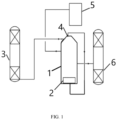
- FIG. 1 is the schematic figure of the separation apparatus for CO 2 -containing phase change solution provided by a preferred embodiment of the present invention.
- any value of the ranges disclosed herein are not limited to the precise ranges or values. Such ranges or values shall be comprehended as comprising the values adjacent to the ranges or the values.
- numerical ranges the endpoint values of each range, the endpoint values of each range and the individual point values, and the individual point values can be combined with one another to obtain one or more new numerical ranges, which should be deemed to have been specifically disclosed herein.
- the phase change solution refers to liquid-liquid phase change absorbent, that is, the phase change solution still exists in the form of a liquid phase after absorbing CO 2 , and because the CO 2 load is different, the CO 2 -lean solution and the CO 2 -rich solution will separate into two distinct phases.
- the first aspect of the present invention provides a separation method for CO 2 -containing phase change solution.
- the method includes: using bubbles to disturb CO 2 -containing phase change solution in order to obtain at least two separated liquid phases.
- the bubbles and the CO 2 -containing phase change solution will form an non-uniform multiphase system.
- the bubbles will combine with the less dense solution system and move upward together to accelerate the separation of different density solution system.
- the thrust effect generated by the bubble generator can promote the form of eddy current in the phase separator, which further accelerates the separation of different density solution system and improves the separation efficiency of the phase change solution, increases the capture rate with the same raw gas material and solvent circulation.
- the size of the bubbles can be selected in a wide range.
- the diameter of the bubbles is not more than 50 ⁇ m, including but not limited to 50 ⁇ m, 45 ⁇ m, 42 ⁇ m, 40 ⁇ m, 38 ⁇ m, 35 ⁇ m, 33 ⁇ m, 32 ⁇ m, 30 ⁇ m, 25 ⁇ m, 20 ⁇ m, 18 ⁇ m, 15 ⁇ m, 10 ⁇ m, 5 ⁇ m, preferably 15-30 ⁇ m.
- the gas-liquid volume ratio between the gas used to generate bubbles and the CO 2 -containing phase change solution is not particularly limited. According to a preferred embodiment of the present invention, the gas-liquid volume ratio between the gas used to generate bubbles and the CO 2 -containing phase change solution is 10-90, including but not limited to 10, 20, 30, 40, 50, 60, 70, 80, 90, preferably 20-50.
- the source of the gas used to generate bubbles is not particularly limited, as long as it does not react with the phase change solution.
- the gas used to generate bubbles is selected from inert gases, preferably one or more of CO 2 , nitrogen and helium, and more preferably CO 2 .
- the gas that generates bubbles is inert gas such as CO 2 , which can also remove dissolved oxygen in the lower CO 2 -rich liquid phase and improve the antioxidant performance, so the lower CO 2 -rich liquid phase can be used for a long time and the decline rate of amine concentration is significantly reduced.
- the separation conditions of the phase change solution are not particularly limited. Conventional separation conditions in the field are applicable to the present invention.
- the phase change conditions include: separation temperature is 35-60 °C, including but not limited to 35 °C, 40 °C, 45 °C, 48 °C, 50 °C, 55 °C, 60 °C.
- the separation method further includes: regenerating the CO 2 -rich liquid phase in the two separated liquid phases.
- the source of the CO 2 gas is not particularly limited.
- CO 2 in the CO 2 -containing phase change solution comes from flue gas produced by coal-fired power generation and/or steelmaking.
- the CO 2 content of the flue gas is 10-20 vol%.
- the CO 2 content includes but is not limited to 10 vol%, 11 vol%, 12 vol%, 13 vol%, 14 vol%, 15 vol%, 16 vol%, 17 vol%, 18 vol%, 19 vol%, 20 vol%.
- the CO 2 -containing phase change solution contains 2.0-4.8 mol CO 2 /kg solvent, including but not limited to 2.0, 2.2, 2.4, 2.6, 2.8, 3.0, 3.1, 3.2, 3.3, 3.4, 3.5, 3.6, 3.7, 3.8, 3.9, 4.0, 4.1, 4.2, 4.3, 4.4, 4.5, 4.6, 4.7, 4.8 mol CO 2 /kg solvent.
- the solvent in the CO 2 -containing phase change solution, includes a first solvent and optionally a second solvent, wherein the first solvent is selected from organic amines, preferably one or more of alkanolamines, amides and fatty amines.
- the first solvent is selected one or more from monoethanolamine, N-methyldiethanolamine, triethylenetetramine, hydroxyethyl ethylenediamine, 2,2-dimethylcyclopropylformamide, N,N-diethylethanolamine and N,N-dimethylcyclohexylamine.
- the optional second solvent refers that the solvent of the phase change solution may or may not contain second solvent.
- the mass content of the first solvent is 15-80wt%, preferably 15-30wt%.
- the solvent includes both the first solvent and the second solvent.
- the second solvent is selected one or more from C2-C10 alcohols, water, sulfoxides and polyether.
- the second solvent is selected one or more from 1-propanol, n-butanol, t-butanol, water, sulfolane, polyether, 2-amino-2-methyl-1-propanol, triethylene glycol and decanol.
- the solvent of the phase change solution includes: 10-90% monoethanolamine and 10-90% sulfolane based on a scale of 100 wt%.
- the solvent of the phase change solution includes: 10-50% triethylenetetramine, 30-80% N,N-diethylethanolamine and 5-50% 1- propanol based on a scale of 100 wt%.
- the solvent of the phase change solution includes: 10-50% N-methyldiethanolamine, 30-80% n-butanol and 5-50% water based on a scale of 100 wt%.
- the separation method of the CO 2 -containing phase change solution is performed in a separation apparatus, and the separation apparatus includes:
- the separation method of CO 2 -containing phase change solutionthe is performed in a separation apparatus, and the apparatus includes:
- the second aspect of the present invention provides a separation apparatus for CO 2 -containing phase change solution.
- the apparatus includes:
- the apparatus includes:
- the bubble generator / the bubble generation unit can be installed inside or outside the phase separator / the phase separation unit, as long as the generated bubbles can disturb the CO 2 -containing phase change solution.
- the phase separator / the phase separation unit is set to have an internal surface roughness Ra > 0.4 ⁇ m, including but not limited to 0.5, 0.6, 0.7, 0.8, 0.9, 1, 2, 3, 4, 5, 6, 7, 8, 9, 10, 11, 12, 13, 14, 15 ⁇ m, preferably 5-15 ⁇ m.
- the height-to-diameter ratio of the phase separator / the phase separation unit is not less than 4, including but not limited to 4, 5, 6, 7, 8, 9, 10, 11, 12, 13, 14, 15, 16, 17, 18, 19, 20, preferably 10-15.
- a vent valve is provided at the top of the phase separator / the phase separation unit.
- the phase separator / the phase separation unit may or may not be filled with fillers. According to a preferred embodiment of the present invention, there is no filler in the phase separator / the phase separation unit.
- the bubble generator / the bubble generation unit is set at the bottom of the phase separator / the phase separation unit.
- the gas discharged from the exhaust port is processed and returned to the bubble generator / the bubble generation unit.
- solvent A is a mixture of monoethanolamine (MEA) and sulfolane, where the mass content of monoethanolamine is 20%.
- solvent B is a mixture of triethylenetetramine, N,N-diethylethanolamine and 1-propanol, where the mass content of triethylenetetramine is 30%, the mass content of N,N-diethylethanolamine is 50%, and the mass content of 1-propanol is 20%.
- solvent C is a mixture of N-methyldiethanolamine, n-butanol and water, where the mass content of n-butanol is 30%, the mass content of water is 50%, and the mass content of N-methyldiethanolamine is 20%.
- the separation apparatus includes:
- flue gas containing 12 vol% CO 2 is passed into the absorption tower 3 to obtain CO 2 -containing phase change solution.
- the CO 2 -containing phase change solution is input from the absorption tower 3 to the phase separator 1, and gas is introduced into the bubble generator 2 installed in the phase separator 1 to generate bubbles to disturb the CO 2 -containing phase change solution in the phase separator 1 to obtain the lower CO 2 -rich liquid phase and the upper CO 2 -lean liquid phase;
- the CO 2 capture rate refers to the ratio of the difference between the content of CO 2 in the raw gas and the content of CO 2 in the purified gas to the content of CO 2 in the raw gas.
- the antioxidant effect is inferred based on the decrease in amine concentration after long-term stable operation.
- concentration of solvent substances such as amine decreases, the better the antioxidant effect.
- the internal surface roughness Ra of the phase separator is 10 ⁇ m.
- the solvent of phase change solution is solvent A, and the flow rate of phase change solution is 25 L/h. the height-to-diameter ratio of phase separator is 5.
- the flow rate of nitrogen is 250 L/h, the diameter of bubbles is 50 ⁇ m, and the volume ratio of nitrogen to phase change solution is 10.
- the separation temperature is 40 °C.
- the CO 2 -containing phase change solution contains 3.4 mol CO 2 /kg solvent.
- the CO 2 capture rate is 90%. After 240 hours of operation, the amine concentration of the lower CO 2 -rich liquid phase dropped by 2%.
- Example 1 Compared with Example 1, the difference is that the flow rate of phase change solution is 20 L/h, and the volume ratio of nitrogen to phase change solution is 12.5. Other conditions in this example are the same as in Example 1.
- the CO 2 -containing phase change solution contains 3.35 mol CO 2 /kg solvent.
- the CO 2 capture rate is 88%. After 240 hours of operation, the amine concentration of the lower CO 2 -rich liquid phase dropped by 2.1%.
- Example 1 Compared with Example 1, the difference is that the flow rate of phase change solution is 20 L/h, the flow rate of nitrogen is 500 L/h, and the volume ratio of nitrogen to phase change solution is 25. Other conditions in this example are the same as in Example 1.
- the CO 2 -containing phase change solution contains 3.41mol CO 2 /kg solvent.
- the CO 2 capture rate is 90.2%. After 240 hours of operation, the amine concentration of the lower CO 2 -rich liquid phase dropped by 2.0%. Compared with Example 1, the flow rate of solvent A is reduced and the flow rate of nitrogen is increased. As a result, the CO 2 capture rate is equivalent to that of Example 1.
- Example 2 Compared with Example 2, the difference is that the diameter of bubbles is 30 ⁇ m. Other conditions in this example are the same as in Example 2.
- the CO 2 -containing phase change solution contains 3.38mol CO 2 /kg solvent.
- the CO 2 capture rate is 89.1%. After 240 hours of operation, the amine concentration of the lower CO 2 -rich liquid phase dropped by 2.1%.
- Example 3 Compared with Example 3, the difference is that the diameter of bubbles is 30 ⁇ m. Other conditions in this example are the same as in Example 3.
- the CO 2 -containing phase change solution contains 3.43mol CO 2 /kg solvent.
- the CO 2 capture rate is 91%. After 240 hours of operation, the amine concentration of the lower CO 2 -rich liquid phase dropped by 1.9%.
- Example 1 Compared with Example 1, the difference is that the height-to-diameter ratio of phase separator is 10. Other conditions in this example are the same as in Example 1.
- the CO 2 -containing phase change solution contains 3.45 mol CO 2 /kg solvent.
- the CO 2 capture rate is 92%. After 240 hours of operation, the amine concentration of the lower CO 2 -rich liquid phase dropped by 1.9%.
- the solvent of phase change solution is solvent B, and the flow rate of phase change solution is 30 L/h. the height-to-diameter ratio of phase separator is 10.
- the flow rate of nitrogen is 500 L/h, the diameter of bubbles is 30 ⁇ m, and the volume ratio of nitrogen to phase change solution is 16.67.
- the separation temperature is 40 °C.
- the CO 2 -containing phase change solution contains 3.5mol CO 2 /kg solvent.
- the CO 2 capture rate is 91%. After 240 hours of operation, the amine concentration of the lower CO 2 -rich liquid phase dropped by 2.0%.
- the solvent of phase change solution is solution C, and the flow rate of phase change solution is 20 L/h.
- the height-to-diameter ratio of phase separator is 10.
- the flow rate of nitrogen is 500 L/h, the diameter of bubbles is 30 ⁇ m, and the volume ratio of nitrogen to phase change solution is 25.
- the separation temperature is 40 °C.
- the CO 2 -containing phase change solution contains 4.0mol CO 2 /kg solvent.
- the CO 2 capture rate is 95%. After 240 hours of operation, the amine concentration of the lower CO 2 -rich liquid phase dropped by 1.8%.
- Example 1 Compared with Example 1, the difference is that CO 2 is passed into the bubble generator installed in phase separator to generate bubbles to disturb the CO 2 -containing phase change solution in phase separator to obtain the lower CO 2 -rich liquid phase and the upper CO 2 -lean liquid phase.
- Other conditions in this example are the same as in Example 1.
- the CO 2 -containing phase change solution contains 4.0mol CO 2 /kg solvent.
- the CO 2 capture rate is 95%. After 240 hours of operation, the amine concentration of the lower CO 2 -rich liquid phase dropped by 1.6%.
- the solvent of phase change solution is solvent A, and the flow rate of phase change solution is 25 L/h. the height-to-diameter ratio of phase separator is 5.
- the bubble generator is turned off.
- the separation temperature is 40 °C.
- the CO 2 -containing phase change solution contains 3.4 mol CO 2 / kg solvent.
- the CO 2 capture rate is 80%. After 240 hours of operation, the amine concentration of the lower CO 2 -rich liquid phase dropped by 2.8%.
Landscapes
- Chemical & Material Sciences (AREA)
- Chemical Kinetics & Catalysis (AREA)
- Engineering & Computer Science (AREA)
- Analytical Chemistry (AREA)
- General Chemical & Material Sciences (AREA)
- Oil, Petroleum & Natural Gas (AREA)
- Physics & Mathematics (AREA)
- Thermal Sciences (AREA)
- Gas Separation By Absorption (AREA)
- Treating Waste Gases (AREA)
- Carbon And Carbon Compounds (AREA)
Abstract
Description
- This application claims the benefit of the
Chinese patent application No. "202210970449.5", filed on August 12, 2022 - The invention relates specifically to a separation method and a separation apparatus for CO2-containing phase change solution.
- Carbon dioxide (CO2) capture technology is the most effective and the rapidest way to solve the current problem of huge carbon emissions. Currently, there are three main types of CO2 capture technologies being vigorously developed, namely post-combustion decarbonization technology, pre-combustion decarbonization technology and oxy-fuel combustion technology. No matter which capture technology is used, the key technology is separation of CO2, that is, to separate CO2 from other substances for subsequent processing. Classified by separation principle, power and carrier, CO2 separation technology mainly includes: absorption, adsorption, membrane separation, cryogenic separation, etc.
- According to the current technological progress, the absorption is the most mature and the most widely used CO2 separation technology. The process of chemical absorption represented by monoethanolamine (MEA) chemical absorption is already very mature. In the alkanolamine-based CO2 capture technology, the heat required for the regeneration process accounts for a significant proportion of the energy consumption of the entire process. At present, there are two main ways to reduce energy consumption: the first is to develop new solvents which can reduce the activation energy required for the regeneration reaction by the steric-hindrance effect or the activation effect of the solvent, or reduce the required amount of solvent during regeneration by the phase change effect of the solvent; the second is to optimize the heat exchange network of the process through thermal coupling to improve the energy utilization efficiency of the entire process.
- The phase change absorbent becomes two liquid phases with a large difference in CO2 loading after absorbing CO2. After separation, the lower layer in which almost all CO2 is concentrated is sent to the desorption tower, and the upper layer returns directly to the absorption tower. So compared with the traditional chemical absorption method, this process can reduce the amount of liquid entering the desorption tower with the same CO2 removal amount, thereby reducing desorption energy consumption.
-
CN102500195A announces a two-phase CO2 capture apparatus in the field of flue gas purification technology. It specifically discloses an apparatus that has one more separator than the traditional capture apparatus. The solution contained in the separator will be divided into two liquid phases with significantly different CO2 contents. The separated upper and lower liquid phases can be obtained by settling, centrifugal separation or filtration. After separation, the upper liquid is directly recycled, and the lower liquid is sent to the desorption tower for regeneration. This apparatus significantly reduces the energy consumption of CO2 capture by chemical absorption, thereby reducing the cost of large-scale application of this technology. This technology focuses on two-phase CO2 capture apparatus. -
CN107519732A discloses a regeneration method for strengthening organic phase of the phase change absorbent after desulfurization and decarburization. It proposes that the organic phase from the separator first passes through the standing wave acoustic processor in the boiler to exert displacement effect, cavitation effect and resonance effect of ultrasonic waves on it, which easily breaks the carbamate bonds in the organic phase generating organic amines and CO2. CO2 is sent to the regeneration gas separator from the bottom of the regeneration tower, and the regenerated organic amines are returned to the absorption tower for absorption through the lean liquid pump. Among them, the displacement effects of ultrasonic waves can cause the regenerated materials in the organic phase to continuously move, collide, and condense toward antinodes or nodes; the strong impact force and the high-speed microjets generated by the cavitation effect can reduce the frictional resistance of collision, cohesion, and sedimentation of the regenerated materials, and the thermal effect generated at the same time can reduce the viscosity. -
CN109092020A provides a CO2 capture system suitable for phase change absorbent, which includes absorption tower, phase separator, rich phase pump, at least one interstage separator, at least one interstage cooler, mixer, rich liquid pump and desorption tower. The absorption tower includes the tower cavity. The part of the tower cavity between the first entrance of the absorption tower and the second entrance of the absorption tower is divided into multiple stages. Each stage of the tower cavity stores poor liquid containing phase change absorbent, and the phase change absorbent contains nanoparticles. All interstage separators are connected to outlet of the corresponding stage of the absorption tower. The reaction of alkali metals with part of heteroatoms and/or one or more heavy metals, that is, the alkali metal desulfurization method, can improve the quality of raw materials. However, the efficiency of the reaction process of this method is low, especially the utilization rate of alkali metals is not high, and the product contains unreacted alkali metal, which needs to be further processed to meet the requirements of low-sulfur marine fuel oil. How to achieve efficient application of alkali metal desulfurization technology in the production of low-sulfur marine fuel oil is an urgent problem that needs to be overcome in the oil refining field. - According to the current published literatures and patents, a large amount of research is mainly carried out around the formulation of phase change absorbent. As mentioned above, the existing technology is mainly focused on the formulation of phase change solvent. However, the stratification of phase change stratification is often achieved by separators that mainly rely on static separation to obtain the two layers. The problem of long static separation time is often overlooked. In order to achieve stable gas processing capacity, continuity of experiments and high adsorption capacity of the solvent, it has to be solved by increasing solution circulation.
- On the one hand, the purpose of the present invention is to overcome the problems of long static separation time and insufficient continuity with the same circulation and gas processing capacity in the traditional process of CO2 capture with phase change absorbent in the existing technology. On the other hand, the purpose of the present invention is also to overcome the problem of weak antioxidant performance of phase change absorbent and provide a separation method and a separation apparatus for CO2-containing phase change solution. This method improves the separation efficiency of phase change solvent through bubbles disturbing. And increase the capture rate with the same raw gas material and solvent circulation.
- In order to achieve the above object, the first aspect of the present invention provides a separation method for CO2-containing phase change solution. The method includes: using bubbles to disturb CO2-containing phase change solution in order to obtain at least two separated liquid phases.
- The second aspect of the present invention provides a separation apparatus for CO2-containing phase change solution. The apparatus includes:
- an absorption unit for phase change solution to absorb CO2 to provide the CO2-containing phase change solution;
- a phase separation unit with an exhaust port for separating the CO2-containing phase change solution to obtain CO2-rich liquid phase and CO2-lean liquid phase;
- a bubble generation unit for generating bubbles to disturb the CO2-containing phase change solution in the phase separation unit;
- optionally a regeneration unit is included in connection with the phase separation unit for collecting the CO2-rich liquid phase from the phase separation unit and processing regeneration;
- optionally a collection unit is included in connection with the phase separation unit for collecting the CO2-lean liquid phase from the phase separation unit.
- Through the above technical solution, the present invention uses bubbles to disturb CO2-containing phase change solution in order to obtain at least two separated liquid phases. The bubbles and the CO2-containing phase change solution will form an non-uniform multiphase system. During the process of bubble uplift, the bubbles will combine with the less dense solution system and move upward together to accelerate the separation of different density solution system. At the same time, the thrust effect generated by the bubble generator can promote the form of eddy current in the phase separator, which further accelerates the separation of different density solution system and improves the separation efficiency of the phase change solution. Compared with traditional cyclone separation and other methods, the separation method of the present invention can improve the separation efficiency of phase change solvent, increase the capture rate with the same raw gas material and solvent circulation and reduce the footprint of the processing unit. Moreover, the parameters of bubble generator can be flexibly adjusted according to the actual separation effect to ensure stable system operation and avoid energy waste. At the same time, bubbles gas can be recovered and recycled as a gas source for the bubble generator.
- In the preferred embodiment of the present invention, the gas that generates bubbles is inert gas such as CO2, which can also remove dissolved oxygen in the lower CO2-rich liquid phase and improve the antioxidant performance, so the lower CO2-rich liquid phase can be used for a long time and the decline rate of amine concentration is significantly reduced.
-
FIG. 1 is the schematic figure of the separation apparatus for CO2-containing phase change solution provided by a preferred embodiment of the present invention. -
- 1- phase separator;
- 2- bubble generator;
- 3- absorption tower;
- 4- exhaust port;
- 5- lean liquid mixing tank;
- 6- regeneration tower.
- The endpoints and any value of the ranges disclosed herein are not limited to the precise ranges or values. Such ranges or values shall be comprehended as comprising the values adjacent to the ranges or the values. As for numerical ranges, the endpoint values of each range, the endpoint values of each range and the individual point values, and the individual point values can be combined with one another to obtain one or more new numerical ranges, which should be deemed to have been specifically disclosed herein.
- In the present invention, the phase change solution refers to liquid-liquid phase change absorbent, that is, the phase change solution still exists in the form of a liquid phase after absorbing CO2, and because the CO2 load is different, the CO2-lean solution and the CO2-rich solution will separate into two distinct phases.
- The first aspect of the present invention provides a separation method for CO2-containing phase change solution. The method includes: using bubbles to disturb CO2-containing phase change solution in order to obtain at least two separated liquid phases. The bubbles and the CO2-containing phase change solution will form an non-uniform multiphase system. During the process of bubble uplift, the bubbles will combine with the less dense solution system and move upward together to accelerate the separation of different density solution system. At the same time, the thrust effect generated by the bubble generator can promote the form of eddy current in the phase separator, which further accelerates the separation of different density solution system and improves the separation efficiency of the phase change solution, increases the capture rate with the same raw gas material and solvent circulation.
- In the present invention, using bubbles to disturb CO2-containing phase change solution can improve the separation efficiency of the phase change solution. The size of the bubbles can be selected in a wide range. According to a preferred embodiment of the present invention, the diameter of the bubbles is not more than 50 µm, including but not limited to 50 µm, 45 µm, 42 µm, 40 µm, 38 µm, 35 µm, 33 µm, 32 µm, 30 µm, 25 µm, 20 µm, 18 µm, 15 µm, 10 µm, 5 µm, preferably 15-30 µm.
- In the present invention, the gas-liquid volume ratio between the gas used to generate bubbles and the CO2-containing phase change solution is not particularly limited. According to a preferred embodiment of the present invention, the gas-liquid volume ratio between the gas used to generate bubbles and the CO2-containing phase change solution is 10-90, including but not limited to 10, 20, 30, 40, 50, 60, 70, 80, 90, preferably 20-50.
- In the present invention, the source of the gas used to generate bubbles is not particularly limited, as long as it does not react with the phase change solution. According to a preferred embodiment of the present invention, the gas used to generate bubbles is selected from inert gases, preferably one or more of CO2, nitrogen and helium, and more preferably CO2. In the present invention, the gas that generates bubbles is inert gas such as CO2, which can also remove dissolved oxygen in the lower CO2-rich liquid phase and improve the antioxidant performance, so the lower CO2-rich liquid phase can be used for a long time and the decline rate of amine concentration is significantly reduced.
- In the present invention, the separation conditions of the phase change solution are not particularly limited. Conventional separation conditions in the field are applicable to the present invention. Preferably, the phase change conditions include: separation temperature is 35-60 °C, including but not limited to 35 °C, 40 °C, 45 °C, 48 °C, 50 °C, 55 °C, 60 °C.
- According to the present invention, preferably, the separation method further includes: regenerating the CO2-rich liquid phase in the two separated liquid phases.
- In the present invention, the source of the CO2 gas is not particularly limited. According to a preferred embodiment of the present invention, CO2 in the CO2-containing phase change solution comes from flue gas produced by coal-fired power generation and/or steelmaking. Preferably, the CO2 content of the flue gas is 10-20 vol%. For example, the CO2 content includes but is not limited to 10 vol%, 11 vol%, 12 vol%, 13 vol%, 14 vol%, 15 vol%, 16 vol%, 17 vol%, 18 vol%, 19 vol%, 20 vol%.
- According to a preferred embodiment of the present invention, the CO2-containing phase change solution contains 2.0-4.8 mol CO2/kg solvent, including but not limited to 2.0, 2.2, 2.4, 2.6, 2.8, 3.0, 3.1, 3.2, 3.3, 3.4, 3.5, 3.6, 3.7, 3.8, 3.9, 4.0, 4.1, 4.2, 4.3, 4.4, 4.5, 4.6, 4.7, 4.8 mol CO2/kg solvent.
- In the present invention, there is no particular limitation on the type of solvent in the phase change solution. All conventional solvents in the field can be used in the present invention. According to a preferred embodiment of the present invention, in the CO2-containing phase change solution, the solvent includes a first solvent and optionally a second solvent, wherein the first solvent is selected from organic amines, preferably one or more of alkanolamines, amides and fatty amines.
- According to a preferred embodiment of the present invention, for example, the first solvent is selected one or more from monoethanolamine, N-methyldiethanolamine, triethylenetetramine, hydroxyethyl ethylenediamine, 2,2-dimethylcyclopropylformamide, N,N-diethylethanolamine and N,N-dimethylcyclohexylamine. In the present invention, the optional second solvent refers that the solvent of the phase change solution may or may not contain second solvent.
- According to a preferred embodiment of the present invention, based on the total mass of the solvent, the mass content of the first solvent is 15-80wt%, preferably 15-30wt%.
- According to a preferred embodiment of the present invention, the solvent includes both the first solvent and the second solvent. Preferably, the second solvent is selected one or more from C2-C10 alcohols, water, sulfoxides and polyether.
- According to a preferred embodiment of the present invention, the second solvent is selected one or more from 1-propanol, n-butanol, t-butanol, water, sulfolane, polyether, 2-amino-2-methyl-1-propanol, triethylene glycol and decanol.
- According to a preferred embodiment of the present invention, the solvent of the phase change solution includes: 10-90% monoethanolamine and 10-90% sulfolane based on a scale of 100 wt%.
- According to a preferred embodiment of the present invention, the solvent of the phase change solution includes: 10-50% triethylenetetramine, 30-80% N,N-diethylethanolamine and 5-50% 1- propanol based on a scale of 100 wt%.
- According to a preferred embodiment of the present invention, the solvent of the phase change solution includes: 10-50% N-methyldiethanolamine, 30-80% n-butanol and 5-50% water based on a scale of 100 wt%.
- The method of the present invention can be implemented in any way. As long as it is operated according to the idea of the present invention, the purpose of the present invention can be achieved. According to a preferred embodiment of the present invention, the separation method of the CO2-containing phase change solution is performed in a separation apparatus, and the separation apparatus includes:
- a phase separation unit for separating the CO2-containing phase change solution to obtain CO2-rich liquid phase and CO2-lean liquid phase, and the phase separation unit is provided with an exhaust port;
- a bubble generation unit for generating bubbles to disturb the CO2-containing phase change solution in the phase separation unit;
- the separation method includes:
the bubbles generated by the bubble generation unit disturb the CO2-containing phase change solution in the phase separation unit, and the gas generated by the bubble generation unit is discharged through the exhaust port. - According to a preferred embodiment of the present invention, the separation method of CO2-containing phase change solutionthe is performed in a separation apparatus, and the apparatus includes:
- a phase separator for separating CO2-containing phase change solution to obtain the upper CO2-rich liquid phase and the lower CO2-lean liquid phase, and the phase separator is provided with an exhaust port;
- a bubble generator for generating bubbles to disturb the CO2-containing phase change solution in the phase separator;
- the separation method includes:
the bubbles generated by the bubble generator disturb the CO2-containing phase change solution in the phase separator, and the gas generated by the bubble generator is discharged through the exhaust port. - According to a preferred embodiment of the present invention, the second aspect of the present invention provides a separation apparatus for CO2-containing phase change solution. The apparatus includes:
- an absorption unit for phase change solution to absorb CO2 to provide the CO2-containing phase change solution;
- a phase separation unit with an exhaust port for separating the CO2-containing phase change solution to obtain CO2-rich liquid phase and CO2-lean liquid phase;
- a bubble generation unit for generating bubbles to disturb the CO2-containing phase change solution in the phase separation unit;
- optionally a regeneration unit is included in connection with the phase separation unit for collecting the CO2-rich liquid phase from the phase separation unit and processing regeneration;
- optionally a collection unit is included in connection with the phase separation unit for collecting the CO2-lean liquid phase from the phase separation unit.
- According to a preferred embodiment of the present invention, the apparatus includes:
- an absorption tower for phase change solution to absorb CO2 to provide the CO2-containing phase change solution;
- a phase separator with an exhaust port at the upper end for separating the CO2-containing phase change solution to obtain the lower CO2-rich liquid phase and the upper CO2-lean liquid phase;
- a bubble generator for generating bubbles to disturb the CO2-containing phase change solution in the phase separator;
- a regeneration tower connected to the lower outlet of the phase separator to collect the lower CO2-rich liquid phase in the phase separator and process regeneration;
- a lean liquid mixing tank connected to the side outlet of the phase separator to collect the upper CO2-lean liquid phase in the phase separator.
- In the present invention, the bubble generator / the bubble generation unit can be installed inside or outside the phase separator / the phase separation unit, as long as the generated bubbles can disturb the CO2-containing phase change solution.
- According to a preferred embodiment of the present invention, the phase separator / the phase separation unit is set to have an internal surface roughness Ra > 0.4 µm, including but not limited to 0.5, 0.6, 0.7, 0.8, 0.9, 1, 2, 3, 4, 5, 6, 7, 8, 9, 10, 11, 12, 13, 14, 15 µm, preferably 5-15 µm.
- According to a preferred embodiment of the present invention, the height-to-diameter ratio of the phase separator / the phase separation unit is not less than 4, including but not limited to 4, 5, 6, 7, 8, 9, 10, 11, 12, 13, 14, 15, 16, 17, 18, 19, 20, preferably 10-15.
- According to a preferred embodiment of the present invention, a vent valve is provided at the top of the phase separator / the phase separation unit.
- In the present invention, the phase separator / the phase separation unit may or may not be filled with fillers. According to a preferred embodiment of the present invention, there is no filler in the phase separator / the phase separation unit.
- In the present invention, there is no special requirement for the location of the bubble generator / the bubble generation unit, as long as it can disturb CO2-containing phase change solution. According to a preferred embodiment of the present invention, the bubble generator / the bubble generation unit is set at the bottom of the phase separator / the phase separation unit.
- According to a preferred embodiment of the present invention, the gas discharged from the exhaust port is processed and returned to the bubble generator / the bubble generation unit.
- The separation method of the CO2-containing phase change solution of the present invention will be further explained through specific examples. The examples are only illustrative of the specific embodiments of the method of the present invention, and do not constitute a limitation on the scope of the present invention.
- In the following examples, solvent A is a mixture of monoethanolamine (MEA) and sulfolane, where the mass content of monoethanolamine is 20%.
- In the following examples, solvent B is a mixture of triethylenetetramine, N,N-diethylethanolamine and 1-propanol, where the mass content of triethylenetetramine is 30%, the mass content of N,N-diethylethanolamine is 50%, and the mass content of 1-propanol is 20%.
- In the following examples, solvent C is a mixture of N-methyldiethanolamine, n-butanol and water, where the mass content of n-butanol is 30%, the mass content of water is 50%, and the mass content of N-methyldiethanolamine is 20%.
- The following examples are performed in the separation apparatus as shown in the schematic diagram of the separation apparatus in
FIG. 1 . The separation apparatus includes: -
absorption tower 3 to provide the CO2-containing phase change solution; - phase separator 1 with exhaust port 4 at the upper end for separating the CO2-containing phase change solution ;
-
bubble generator 2 installed at the bottom of the phase separator 1 for generating bubbles and passing bubbles into the phase separator to disturb the CO2-containing phase change solution. Bubbles are produced by passing gas into thebubble generator 2; -
regeneration tower 6 connected to the lower outlet of the phase separator 1 to collect the lower CO2-rich liquid phase in the phase separator 1 and process regeneration; - lean
liquid mixing tank 5 connected to the side outlet of the phase separator 1 to collect the upper CO2-lean liquid phase in the phase separator 1. - In the following examples, flue gas containing 12 vol% CO2 is passed into the
absorption tower 3 to obtain CO2-containing phase change solution. The CO2-containing phase change solution is input from theabsorption tower 3 to the phase separator 1, and gas is introduced into thebubble generator 2 installed in the phase separator 1 to generate bubbles to disturb the CO2-containing phase change solution in the phase separator 1 to obtain the lower CO2-rich liquid phase and the upper CO2-lean liquid phase; - The lower CO2-rich liquid phase enters the
regeneration tower 6 through the lower outlet of the phase separator 1 and is then regenerated; - The upper CO2-lean liquid phase enters the lean
liquid mixing tank 5 through the side outlet of the phase separator 1. - In the following examples, the CO2 capture rate refers to the ratio of the difference between the content of CO2 in the raw gas and the content of CO2 in the purified gas to the content of CO2 in the raw gas.
- In the following examples, the antioxidant effect is inferred based on the decrease in amine concentration after long-term stable operation. The lower the concentration of solvent substances such as amine decreases, the better the antioxidant effect.
- In the following examples, the internal surface roughness Ra of the phase separator is 10 µm.
- The solvent of phase change solution is solvent A, and the flow rate of phase change solution is 25 L/h. the height-to-diameter ratio of phase separator is 5. The flow rate of nitrogen is 250 L/h, the diameter of bubbles is 50µm, and the volume ratio of nitrogen to phase change solution is 10. The separation temperature is 40 °C.
- The CO2-containing phase change solution contains 3.4 mol CO2 /kg solvent.
- The CO2 capture rate is 90%. After 240 hours of operation, the amine concentration of the lower CO2-rich liquid phase dropped by 2%.
- Compared with Example 1, the difference is that the flow rate of phase change solution is 20 L/h, and the volume ratio of nitrogen to phase change solution is 12.5. Other conditions in this example are the same as in Example 1.
- The CO2-containing phase change solution contains 3.35 mol CO2 /kg solvent.
- The CO2 capture rate is 88%. After 240 hours of operation, the amine concentration of the lower CO2-rich liquid phase dropped by 2.1%.
- Compared with Example 1, the difference is that the flow rate of phase change solution is 20 L/h, the flow rate of nitrogen is 500 L/h, and the volume ratio of nitrogen to phase change solution is 25. Other conditions in this example are the same as in Example 1.
- The CO2-containing phase change solution contains 3.41mol CO2 /kg solvent.
- The CO2 capture rate is 90.2%. After 240 hours of operation, the amine concentration of the lower CO2-rich liquid phase dropped by 2.0%. Compared with Example 1, the flow rate of solvent A is reduced and the flow rate of nitrogen is increased. As a result, the CO2 capture rate is equivalent to that of Example 1.
- Compared with Example 2, the difference is that the diameter of bubbles is 30µm. Other conditions in this example are the same as in Example 2.
- The CO2-containing phase change solution contains 3.38mol CO2 /kg solvent.
- The CO2 capture rate is 89.1%. After 240 hours of operation, the amine concentration of the lower CO2-rich liquid phase dropped by 2.1%.
- Compared with Example 3, the difference is that the diameter of bubbles is 30µm. Other conditions in this example are the same as in Example 3.
- The CO2-containing phase change solution contains 3.43mol CO2 /kg solvent.
- The CO2 capture rate is 91%. After 240 hours of operation, the amine concentration of the lower CO2-rich liquid phase dropped by 1.9%.
- Compared with Example 1, the difference is that the height-to-diameter ratio of phase separator is 10. Other conditions in this example are the same as in Example 1.
- The CO2-containing phase change solution contains 3.45 mol CO2 /kg solvent.
- The CO2 capture rate is 92%. After 240 hours of operation, the amine concentration of the lower CO2-rich liquid phase dropped by 1.9%.
- The solvent of phase change solution is solvent B, and the flow rate of phase change solution is 30 L/h. the height-to-diameter ratio of phase separator is 10. The flow rate of nitrogen is 500 L/h, the diameter of bubbles is 30µm, and the volume ratio of nitrogen to phase change solution is 16.67. The separation temperature is 40 °C.
- The CO2-containing phase change solution contains 3.5mol CO2 /kg solvent.
- The CO2 capture rate is 91%. After 240 hours of operation, the amine concentration of the lower CO2-rich liquid phase dropped by 2.0%.
- The solvent of phase change solution is solution C, and the flow rate of phase change solution is 20 L/h. the height-to-diameter ratio of phase separator is 10. The flow rate of nitrogen is 500 L/h, the diameter of bubbles is 30µm, and the volume ratio of nitrogen to phase change solution is 25. The separation temperature is 40 °C.
- The CO2-containing phase change solution contains 4.0mol CO2 /kg solvent.
- The CO2 capture rate is 95%. After 240 hours of operation, the amine concentration of the lower CO2-rich liquid phase dropped by 1.8%.
- Compared with Example 1, the difference is that CO2 is passed into the bubble generator installed in phase separator to generate bubbles to disturb the CO2-containing phase change solution in phase separator to obtain the lower CO2-rich liquid phase and the upper CO2-lean liquid phase. Other conditions in this example are the same as in Example 1.
- The CO2-containing phase change solution contains 4.0mol CO2 /kg solvent.
- The CO2 capture rate is 95%. After 240 hours of operation, the amine concentration of the lower CO2-rich liquid phase dropped by 1.6%.
- The solvent of phase change solution is solvent A, and the flow rate of phase change solution is 25 L/h. the height-to-diameter ratio of phase separator is 5. The bubble generator is turned off. The separation temperature is 40 °C. The CO2-containing phase change solution contains 3.4 mol CO2 / kg solvent.
- The CO2 capture rate is 80%. After 240 hours of operation, the amine concentration of the lower CO2-rich liquid phase dropped by 2.8%.
- The above content describes in detail the preferred embodiments of the invention, but the invention is not limited thereto. A variety of simple modifications can be made in regard to the technical solution of the invention within the scope of the technical concept of the invention, including a combination of individual technical features in any other suitable manner. Such simple modifications and combinations thereof shall also be regarded as the content disclosed by the invention, and each of them falls into the protection scope of the invention.
Claims (29)
- A separation method for CO2-containing phase change solution, characterized in that the method includes: using bubbles to disturb CO2-containing phase change solution in order to obtain at least two separated liquid phases.
- The separation method according to claim 1, wherein the diameter of the bubbles is no more than 50 µm.
- The separation method according to claim 1, wherein the diameter of the bubbles is 15-30 µm.
- The separation method according to any one of claims 1-3, wherein the gas-liquid volume ratio between the gas used to generate bubbles and the CO2-containing phase change solution is 10-90.
- The separation method according to any one of claims 1-4, wherein the gas-liquid volume ratio between the gas used to generate bubbles and the CO2-containing phase change solution is 20-50.
- The separation method according to any one of claims 1-5, wherein the gas used to generate bubbles is selected from inert gases.
- The separation method according to any one of claims 1-6, wherein the gas used to generate bubbles is selected one or more from CO2, nitrogen and helium.
- The separation method according to any one of claims 1-7, wherein the gas used to generate bubbles is CO2.
- The separation method according to any one of claims 1-8, wherein the separation conditions include: the separation temperature is 35-60 °C.
- The separation method according to any one of claims 1-9, wherein the method further includes: regenerating the CO2-rich liquid phase in the two separated liquid phases.
- The separation method according to any one of claims 1-10, wherein CO2 in the CO2-containing phase change solution comes from flue gas produced by coal-fired power generation and/or steelmaking.
- The separation method according to claim 11, wherein the CO2 content of the flue gas is 10-20 vol%.
- The separation method according to any one of claims 1-12, wherein the CO2-containing phase change solution contains 2.0-4.8 mol CO2/kg solvent.
- The separation method according to any one of claims 1-13, wherein:the solvent in the CO2-containing phase change solution includes a first solvent and optionally a second solvent, wherein the first solvent is selected from organic amines;the second solvent is selected one or more from C2-C10 alcohols, water, sulfoxides and polyether.
- The separation method according to claim 14, wherein the mass content of the first solvent is 15-80 wt% based on the total mass of the solvent.
- The separation method according to claim 14 or 15, wherein the mass content of the first solvent is 15-30 wt% based on the total mass of the solvent.
- The separation method according to any one of claims 14-16, wherein the first solvent is selected one or more from alkanolamines, amides and fatty amines.
- The separation method according to any one of claims 14-17, wherein the first solvent is selected one or more from monoethanolamine, N-methyldiethanolamine, triethylenetetramine, hydroxyethyl ethylenediamine, 2,2-dimethylcyclopropylformamide, N,N-diethylethanolamine and N,N-dimethylcyclohexylamine.
- The separation method according to any one of claims 14-18, wherein the second solvent is selected one or more from 1-propanol, n-butanol, t-butanol, water, sulfolane, polyether, 2-amino-2-methyl-1-propanol, triethylene glycol and decanol.
- The separation method according to any one of claims 14-19, wherein:the solvent of phase change solution includes: 10-90% monoethanolamine and 10-90% sulfolane based on a scale of 100 wt%; orthe solvent of phase change solution includes: 10-50% triethylenetetramine, 30-80% N,N-diethylethanolamine and 5-50% 1-propanol based on a scale of 100 wt%; orthe solvent of phase change solution includes: 10-50%N-methyldiethanolamine, 30-80% n-butanol and 5-50% water based on a scale of 100 wt%.
- The separation method according to any one of claims 1-20, wherein the method is performed in a separation apparatus of the CO2-containing phase change solution, and the separation apparatus includes:a phase separation unit for separating the CO2-containing phase change solution to obtain CO2-rich liquid phase and CO2-lean liquid phase, and the phase separation unit is provided with an exhaust port;a bubble generation unit for generating bubbles to disturb the CO2-containing phase change solution in the phase separation unit;the separation method includes:
the bubbles generated by the bubble generation unit disturb the CO2-containing phase change solution in the phase separation unit, and the gas generated by the bubble generation unit is discharged through the exhaust port. - The separation method according to any one of claims 1-21, wherein the separation apparatus includes:a phase separator for separating CO2-containing phase change solution to obtain the upper CO2-rich liquid phase and the lower CO2-lean liquid phase, and the phase separator is provided with an exhaust port;a bubble generator for generating bubbles to disturb the CO2-containing phase change solution in the phase separator;the separation method includes:
the bubbles generated by the bubble generator disturb the CO2-containing phase change solution in the phase separator, and the gas generated by the bubble generator is discharged through the exhaust port. - A separation apparatus for CO2-containing phase change solution, characterized in that the apparatus includes:an absorption unit for phase change solution to absorb CO2 to provide the CO2-containing phase change solution;a phase separation unit with an exhaust port for separating the CO2-containing phase change solution to obtain CO2-rich liquid phase and CO2-lean liquid phase;a bubble generation unit for generating bubbles to disturb the CO2-containing phase change solution in the phase separation unit;optionally a regeneration unit is included in connection with the phase separation unit for collecting the CO2-rich liquid phase from the phase separation unit and processing regeneration;optionally a collection unit is included in connection with the phase separation unit for collecting the CO2-lean liquid phase from the phase separation unit.
- The separation apparatus according to claim 23, wherein the apparatus includes:an absorption tower for phase change solution to absorb CO2 to provide the CO2-containing phase change solution;a phase separator with an exhaust port at the upper end for separating the CO2-containing phase change solution to obtain the lower CO2-rich liquid phase and the upper CO2-lean liquid phase;a bubble generator for generating bubbles to disturb the CO2-containing phase change solution in the phase separator;a regeneration tower connected to the lower outlet of the phase separator to collect the lower CO2-rich liquid phase in the phase separator and process regeneration;a lean liquid mixing tank connected to the side outlet of the phase separator to collect the upper CO2-lean liquid phase in the phase separator.
- The separation apparatus according to claims 23 or 24, wherein the phase separator or the phase separation unit is set to have an internal surface roughness Ra > 0.4 µm.
- The separation apparatus according to any one of claims 23-25, wherein the phase separator or the phase separation unit is set to have an internal surface roughness Ra of 5-15 µm.
- The separation apparatus according to any one of claims 23-26, wherein the height-to-diameter ratio of the phase separator or the phase separation unit is not less than 4.
- The separation apparatus according to any one of claims 23-27, wherein the height-to-diameter ratio of the phase separator or the phase separation unit is 10-15.
- The separation apparatus according to any one of claims 23-28, wherein the bubble generator or the bubble generation unit is provided at the bottom of the phase separator or the phase separation unit.
Applications Claiming Priority (2)
| Application Number | Priority Date | Filing Date | Title |
|---|---|---|---|
| CN202210970449.5A CN117618988A (en) | 2022-08-12 | 2022-08-12 | Separation method and separation device for phase change solution containing carbon dioxide |
| PCT/CN2022/138787 WO2024031901A1 (en) | 2022-08-12 | 2022-12-13 | Separation method and separation apparatus for carbon-dioxide-containing phase change solution |
Publications (2)
| Publication Number | Publication Date |
|---|---|
| EP4570354A1 true EP4570354A1 (en) | 2025-06-18 |
| EP4570354A4 EP4570354A4 (en) | 2026-02-18 |
Family
ID=89850523
Family Applications (1)
| Application Number | Title | Priority Date | Filing Date |
|---|---|---|---|
| EP22954839.1A Pending EP4570354A4 (en) | 2022-08-12 | 2022-12-13 | SEPARATION METHOD AND SEPARATION DEVICE FOR A CARBON DIOXIDE-CONTAINING PHASE-CHANGE SOLUTION |
Country Status (4)
| Country | Link |
|---|---|
| US (1) | US20260048359A1 (en) |
| EP (1) | EP4570354A4 (en) |
| CN (1) | CN117618988A (en) |
| WO (1) | WO2024031901A1 (en) |
Family Cites Families (17)
| Publication number | Priority date | Publication date | Assignee | Title |
|---|---|---|---|---|
| US7541011B2 (en) * | 2006-04-07 | 2009-06-02 | Liang Hu | Phase transitional absorption method |
| JP5147200B2 (en) * | 2006-06-26 | 2013-02-20 | 株式会社日立産機システム | Oil / water separator |
| JP5812661B2 (en) * | 2011-04-21 | 2015-11-17 | 三菱重工業株式会社 | Carbon dioxide recovery system |
| KR20130028413A (en) * | 2011-09-09 | 2013-03-19 | 재단법인 포항산업과학연구원 | Apparatus and method for capturing carbon dioxide using microbuble generator |
| CN102500195B (en) | 2011-11-07 | 2013-10-16 | 清华大学 | Two-phase carbon dioxide collecting device |
| JP6121894B2 (en) * | 2013-12-25 | 2017-04-26 | 株式会社東芝 | Acid gas removing device and acid gas removing method |
| JP2015205238A (en) * | 2014-04-18 | 2015-11-19 | 株式会社東芝 | Carbon dioxide recovery device and carbon dioxide recovery method |
| CN107519732A (en) | 2016-06-20 | 2017-12-29 | 中国石油化工股份有限公司 | A kind of renovation process for organic phase after reinforced transformation absorbent desulfurization and decarburization |
| CN207552015U (en) * | 2017-10-13 | 2018-06-29 | 上海嘉金泵业制造有限公司 | Fully automatic integral slagging-off oil removing sewage disposal device |
| KR102037878B1 (en) * | 2018-02-22 | 2019-10-29 | 서강대학교산학협력단 | Carbon Dioxide Absorbent And Method for Absorbing Carbon Dioxide Using the Same |
| CN110627153A (en) * | 2018-08-07 | 2019-12-31 | 台州多凯工业设计有限公司 | Oil-water separation equipment for scraped car recovery |
| CN109092020A (en) | 2018-10-24 | 2018-12-28 | 中石化石油工程技术服务有限公司 | Carbon dioxide capture system suitable for phase transformation absorbent |
| CN114159954B (en) * | 2021-12-07 | 2024-03-15 | 兰州理工大学 | Phase-change solvent coupling membrane for separating flue gas CO 2 Systems and methods of (1) |
| CN114191975B (en) * | 2021-12-31 | 2025-10-03 | 河北科技大学 | A CO2 capture absorbent with secondary phase change function and its application method |
| CN114602294A (en) * | 2022-02-25 | 2022-06-10 | 昆明理工大学 | For capturing CO2Two-phase absorbent and its use |
| CN114832593B (en) * | 2022-05-13 | 2025-11-07 | 嘉兴市碳捕手科技有限责任公司 | Liquid-liquid split-phase type carbon dioxide absorbing and desorbing system |
| CN218589741U (en) * | 2022-08-12 | 2023-03-10 | 中国石油化工股份有限公司 | Separating device for carbon dioxide-containing phase-change solution |
-
2022
- 2022-08-12 CN CN202210970449.5A patent/CN117618988A/en active Pending
- 2022-12-13 US US19/103,317 patent/US20260048359A1/en active Pending
- 2022-12-13 EP EP22954839.1A patent/EP4570354A4/en active Pending
- 2022-12-13 WO PCT/CN2022/138787 patent/WO2024031901A1/en not_active Ceased
Also Published As
| Publication number | Publication date |
|---|---|
| EP4570354A4 (en) | 2026-02-18 |
| WO2024031901A1 (en) | 2024-02-15 |
| US20260048359A1 (en) | 2026-02-19 |
| CN117618988A (en) | 2024-03-01 |
Similar Documents
| Publication | Publication Date | Title |
|---|---|---|
| CN101456556B (en) | A device and method for industrial separation and purification of CO2 in mixed gas by hydrate method | |
| US9533247B2 (en) | Method and apparatus for micro-hydrocyclone purification for flue gas carbon dioxide capture system | |
| CN116556909B (en) | A device and method for high-efficiency separation and recycling of carbon dioxide | |
| EP3034153A1 (en) | Methods and systems for deacidizing gaseous mixtures by means of an absorbent with an organic phase and a carrier phase | |
| EP2424645A1 (en) | Self-concentrating absorbent for acid gas separation | |
| CN104673367A (en) | Step-by-step oil-water mixture separation method coupled with oil gas washing | |
| CN100493672C (en) | Hydrate process and apparatus for separating gas mixture continuously | |
| CN201008761Y (en) | Gas-liquid-solid mixed phase flow separating device for stone oil project | |
| CN102806001B (en) | Method and device for selectively removing hydrogen sulfide by use of ultrasonically atomized liquid droplets | |
| CN117942620A (en) | Method and system for efficiently separating carbon dioxide phase change solution | |
| CN106311149A (en) | Absorbent used for natural gas decarburization | |
| CN102423620A (en) | Compound decarbonizing solvent for removing carbon dioxide from biogas | |
| CN218589741U (en) | Separating device for carbon dioxide-containing phase-change solution | |
| CN110152453A (en) | Use the method and apparatus of sour gas in solvent absorption captured gas mixture | |
| CN102125795A (en) | A method and device for removing CO2 from synthetic ammonia shift gas | |
| US20260048359A1 (en) | Separation method and separation apparatus for co2-containing phase change solution | |
| CN102151477A (en) | Method and device for rotationally purifying serotonin solution of flue gas carbon dioxide capturing system | |
| CN103585883A (en) | Technology and device for recovering volatile tail gas in sulfur collection pit of sulfur device of oil refinery | |
| CN102114359A (en) | Micro-cyclone liquid collecting method and device for regeneration gas of flue gas and carbon dioxide capture system | |
| CN204093274U (en) | Flue gas desulphurization system | |
| CN116196726A (en) | Carbon dioxide trapping system for mineralized aerated block production | |
| EP3666366B1 (en) | Composite decarbonization solution added with carbon nano tube for recycling carbon dioxide in a mixed gas | |
| EP4703023A1 (en) | Absorption liquid for capturing carbon dioxide and use thereof, and method for capturing carbon dioxide | |
| CN109569242A (en) | Strengthen solution-air-liquid tri-phase system and absorbs CO2Method | |
| CN111099984B (en) | Recovery method of purge gas in process of preparing oxalate through CO coupling |
Legal Events
| Date | Code | Title | Description |
|---|---|---|---|
| STAA | Information on the status of an ep patent application or granted ep patent |
Free format text: STATUS: THE INTERNATIONAL PUBLICATION HAS BEEN MADE |
|
| PUAI | Public reference made under article 153(3) epc to a published international application that has entered the european phase |
Free format text: ORIGINAL CODE: 0009012 |
|
| STAA | Information on the status of an ep patent application or granted ep patent |
Free format text: STATUS: REQUEST FOR EXAMINATION WAS MADE |
|
| 17P | Request for examination filed |
Effective date: 20250311 |
|
| AK | Designated contracting states |
Kind code of ref document: A1 Designated state(s): AL AT BE BG CH CY CZ DE DK EE ES FI FR GB GR HR HU IE IS IT LI LT LU LV MC ME MK MT NL NO PL PT RO RS SE SI SK SM TR |
|
| DAV | Request for validation of the european patent (deleted) | ||
| DAX | Request for extension of the european patent (deleted) | ||
| A4 | Supplementary search report drawn up and despatched |
Effective date: 20260121 |
|
| RIC1 | Information provided on ipc code assigned before grant |
Ipc: B01D 53/14 20060101AFI20260115BHEP Ipc: B01D 53/18 20060101ALI20260115BHEP |