EP4570351A1 - Ambient air filter device and filter element in ambient air filter device - Google Patents
Ambient air filter device and filter element in ambient air filter device Download PDFInfo
- Publication number
- EP4570351A1 EP4570351A1 EP23215701.6A EP23215701A EP4570351A1 EP 4570351 A1 EP4570351 A1 EP 4570351A1 EP 23215701 A EP23215701 A EP 23215701A EP 4570351 A1 EP4570351 A1 EP 4570351A1
- Authority
- EP
- European Patent Office
- Prior art keywords
- filter element
- filter
- ambient air
- installation frame
- filter device
- Prior art date
- Legal status (The legal status is an assumption and is not a legal conclusion. Google has not performed a legal analysis and makes no representation as to the accuracy of the status listed.)
- Granted
Links
Images




Classifications
-
- B—PERFORMING OPERATIONS; TRANSPORTING
- B01—PHYSICAL OR CHEMICAL PROCESSES OR APPARATUS IN GENERAL
- B01D—SEPARATION
- B01D46/00—Filters or filtering processes specially modified for separating dispersed particles from gases or vapours
- B01D46/52—Particle separators, e.g. dust precipitators, using filters embodying folded corrugated or wound sheet material
- B01D46/521—Particle separators, e.g. dust precipitators, using filters embodying folded corrugated or wound sheet material using folded, pleated material
- B01D46/525—Particle separators, e.g. dust precipitators, using filters embodying folded corrugated or wound sheet material using folded, pleated material which comprises flutes
-
- B—PERFORMING OPERATIONS; TRANSPORTING
- B01—PHYSICAL OR CHEMICAL PROCESSES OR APPARATUS IN GENERAL
- B01D—SEPARATION
- B01D46/00—Filters or filtering processes specially modified for separating dispersed particles from gases or vapours
- B01D46/10—Particle separators, e.g. dust precipitators, using filter plates, sheets or pads having plane surfaces
-
- B—PERFORMING OPERATIONS; TRANSPORTING
- B01—PHYSICAL OR CHEMICAL PROCESSES OR APPARATUS IN GENERAL
- B01D—SEPARATION
- B01D46/00—Filters or filtering processes specially modified for separating dispersed particles from gases or vapours
- B01D46/0002—Casings; Housings; Frame constructions
- B01D46/0005—Mounting of filtering elements within casings, housings or frames
-
- B—PERFORMING OPERATIONS; TRANSPORTING
- B01—PHYSICAL OR CHEMICAL PROCESSES OR APPARATUS IN GENERAL
- B01D—SEPARATION
- B01D46/00—Filters or filtering processes specially modified for separating dispersed particles from gases or vapours
- B01D46/0002—Casings; Housings; Frame constructions
- B01D46/001—Means for connecting filter housings to supports
-
- B—PERFORMING OPERATIONS; TRANSPORTING
- B01—PHYSICAL OR CHEMICAL PROCESSES OR APPARATUS IN GENERAL
- B01D—SEPARATION
- B01D46/00—Filters or filtering processes specially modified for separating dispersed particles from gases or vapours
- B01D46/52—Particle separators, e.g. dust precipitators, using filters embodying folded corrugated or wound sheet material
- B01D46/521—Particle separators, e.g. dust precipitators, using filters embodying folded corrugated or wound sheet material using folded, pleated material
-
- B—PERFORMING OPERATIONS; TRANSPORTING
- B60—VEHICLES IN GENERAL
- B60K—ARRANGEMENT OR MOUNTING OF PROPULSION UNITS OR OF TRANSMISSIONS IN VEHICLES; ARRANGEMENT OR MOUNTING OF PLURAL DIVERSE PRIME-MOVERS IN VEHICLES; AUXILIARY DRIVES FOR VEHICLES; INSTRUMENTATION OR DASHBOARDS FOR VEHICLES; ARRANGEMENTS IN CONNECTION WITH COOLING, AIR INTAKE, GAS EXHAUST OR FUEL SUPPLY OF PROPULSION UNITS IN VEHICLES
- B60K11/00—Arrangement in connection with cooling of propulsion units
- B60K11/02—Arrangement in connection with cooling of propulsion units with liquid cooling
-
- B—PERFORMING OPERATIONS; TRANSPORTING
- B60—VEHICLES IN GENERAL
- B60K—ARRANGEMENT OR MOUNTING OF PROPULSION UNITS OR OF TRANSMISSIONS IN VEHICLES; ARRANGEMENT OR MOUNTING OF PLURAL DIVERSE PRIME-MOVERS IN VEHICLES; AUXILIARY DRIVES FOR VEHICLES; INSTRUMENTATION OR DASHBOARDS FOR VEHICLES; ARRANGEMENTS IN CONNECTION WITH COOLING, AIR INTAKE, GAS EXHAUST OR FUEL SUPPLY OF PROPULSION UNITS IN VEHICLES
- B60K11/00—Arrangement in connection with cooling of propulsion units
- B60K11/06—Arrangement in connection with cooling of propulsion units with air cooling
-
- B—PERFORMING OPERATIONS; TRANSPORTING
- B60—VEHICLES IN GENERAL
- B60K—ARRANGEMENT OR MOUNTING OF PROPULSION UNITS OR OF TRANSMISSIONS IN VEHICLES; ARRANGEMENT OR MOUNTING OF PLURAL DIVERSE PRIME-MOVERS IN VEHICLES; AUXILIARY DRIVES FOR VEHICLES; INSTRUMENTATION OR DASHBOARDS FOR VEHICLES; ARRANGEMENTS IN CONNECTION WITH COOLING, AIR INTAKE, GAS EXHAUST OR FUEL SUPPLY OF PROPULSION UNITS IN VEHICLES
- B60K11/00—Arrangement in connection with cooling of propulsion units
- B60K11/08—Air inlets for cooling; Shutters or blinds therefor
-
- B—PERFORMING OPERATIONS; TRANSPORTING
- B60—VEHICLES IN GENERAL
- B60R—VEHICLES, VEHICLE FITTINGS, OR VEHICLE PARTS, NOT OTHERWISE PROVIDED FOR
- B60R19/00—Wheel guards; Radiator guards, e.g. grilles; Obstruction removers; Fittings damping bouncing force in collisions
- B60R19/52—Radiator or grille guards ; Radiator grilles
-
- B—PERFORMING OPERATIONS; TRANSPORTING
- B01—PHYSICAL OR CHEMICAL PROCESSES OR APPARATUS IN GENERAL
- B01D—SEPARATION
- B01D2265/00—Casings, housings or mounting for filters specially adapted for separating dispersed particles from gases or vapours
- B01D2265/02—Non-permanent measures for connecting different parts of the filter
- B01D2265/028—Snap, latch or clip connecting means
-
- B—PERFORMING OPERATIONS; TRANSPORTING
- B01—PHYSICAL OR CHEMICAL PROCESSES OR APPARATUS IN GENERAL
- B01D—SEPARATION
- B01D2273/00—Operation of filters specially adapted for separating dispersed particles from gases or vapours
- B01D2273/10—Allowing a continuous bypass of at least part of the flow, e.g. of secondary air, vents
-
- B—PERFORMING OPERATIONS; TRANSPORTING
- B01—PHYSICAL OR CHEMICAL PROCESSES OR APPARATUS IN GENERAL
- B01D—SEPARATION
- B01D2273/00—Operation of filters specially adapted for separating dispersed particles from gases or vapours
- B01D2273/14—Filters which are moved between two or more positions, e.g. by turning, pushing
-
- B—PERFORMING OPERATIONS; TRANSPORTING
- B01—PHYSICAL OR CHEMICAL PROCESSES OR APPARATUS IN GENERAL
- B01D—SEPARATION
- B01D2279/00—Filters adapted for separating dispersed particles from gases or vapours specially modified for specific uses
- B01D2279/40—Filters adapted for separating dispersed particles from gases or vapours specially modified for specific uses for cleaning of environmental air, e.g. by filters installed on vehicles or on streets
Definitions
- the invention relates to an ambient air filter device for arrangement in a front area of a vehicle as well as a use of a filter element in an ambient air filter device.
- Air filters which are integrated in the front area of vehicles, are usually arranged in a separate filter frame as part of the air duct in front of the radiator.
- DE 102008013501 A1 discloses a filter element for insertion into a filter housing, including a bellows made of a filter medium, which is at least partially surrounded by a frame, and at least one end element, the frame being attached to the bellows and is molded onto the end element. At least on the bellows facing side of the end element undercuts are formed.
- KR 20140147553 A discloses an apparatus for collecting fine dust floating in the air by driving a vehicle without an external power, including an inlet part including an air inlet hole formed on the front end based on the direction of the driving vehicle, a filter part extended from the inlet part and including at least one filter inside, and an outlet part including an air inlet hole extended from the filter part and formed on the back end based on the direction of driving vehicle.
- the air passes through the inlet part, the filter part, and the outlet hole by air when driving the vehicle.
- Another object is to provide a use of a filter element in such an ambient air filter device.
- an ambient air filter device for arrangement in a front area of a vehicle, the ambient air filter device including an installation frame, and a filter element arranged on the installation frame.
- the installation frame includes a flow-through area through which a fluid flow passing through the filter element can pass, and at least one guiding member arranged on opposing sides of the flow-through area and for mounting the filter element along an insertion direction.
- the filter element includes at least one filter medium body having at least one part tiltable about a tilt axis against a through-flow direction of the filter element to provide a bypass channel for the fluid flow to bypass the filter element.
- the further object is achieved by a filter element in the ambient air filter device, the filter element including an air inlet side and an air outlet side through which the fluid flow can pass to the installation frame, has and the at least one filter medium body having the at least one part tiltable about the tilt axis against the through-flow direction of the filter element to provide the bypass channel for the fluid flow to bypass the filter element.
- the proposed ambient air filter device with the filter element serves for filtering air destined to flow through a radiator of a cooler of a vehicle. Therefore the ambient air filter device is arranged in front of the cooler with a design as flat as possible for packaging and assurance classification reasons.
- the embodiments may use a flat flow-through plastic plate, with a mesh-like grid structure, on which the filter element is fixed. Implications on a crash zone of the vehicle may advantageously be prevented.
- the air streams shall be enhanced by opening a bypass and part of the air may flow directly to the cooler and the A/C heat pump.
- the bypass is achieved by tilting at least part of the filter element away from the flow-through area of the installation frame.
- the tilt axis advantageously lies parallel to the installation frame.
- Thermal management in vehicles is a crucial aspect especially for battery electric vehicles which needs to be considered.
- the charging time of the battery is a critical value.
- the most critical case is fast charging of the battery under high outside temperatures together with high load just before starting the battery charging.
- the A/C heat pump needs fresh air to work properly, and blocking of the filter element may prevent the A/C heat pump from receiving fresh air.
- the concept of a flat frame filter device is slightly adapted so it is possible to mount one, two or more parts of a filter element in the frame.
- an actuator or magnets one or more of the lower and/or upper parts are movable in a direction away from the cooler of the vehicle so that a bypass for the air flow is opened.
- the side which is open is depending on assembly space of the cooler pack and the flow path of the air.
- the filter element can be connected, e.g., with a side band, so it is possible to perform a tilting movement of the filter element when opening the bypass.
- the packaging of the filter element can be smaller since the filter element potentially can be folded.
- At least part of the filter element is tiltable so that at least a part of the filter medium body is moved away from the installation frame.
- a filter element In the tilted position, such a filter element enables a bypass for the air normally passing the filter element and in that way makes sure that the thermal management and especially the battery charging time is not affected by the presence of the filter element in front of the radiator of the cooler of the vehicle. Further, the bypass makes sure that the A/C heat pump always receives fresh air so that the A/C heat pump can work properly, even if the filter element is blocked.
- the at least one filter medium body may include a pleated medium.
- the tilt axis may lie substantially parallel to one of pleats of the pleated medium, in particular in one of the pleats of the pleated medium.
- a one-part filter element may be tilted advantageously parallel to a pleat of the filter medium body.
- the ambient air filter device may further include side bands covering at least parts of opposing sides of the at least one filter medium body.
- the side bands enable even a filter element including at least two parts of filter medium bodies to be tilted wherein the parts are kept in a fixed distance to each other by the side bands.
- the side bands may be arranged perpendicular to the tilt axis.
- the ambient air filter device may further include a sealing arranged at least on one side of the at least one filter medium body, in particular pointing in the insertion direction.
- the sealing may be a foam sealing.
- the filter element may be positioned in a sealed position when mounted to a frame of the vehicle.
- the installation frame may further include at least one end stop element for limiting a tilt movement of the at least one part of the at least one filter medium body.
- the end stop element limits a tilt movement of the part of the filter element to be tilted, thus providing a defined bypass opening for the air bypassing the filter element.
- the filter element may include at least two filter medium bodies. At least one of the at least two filter medium bodies may be tiltable about the tilt axis against the through-flow direction of the filter element to provide the bypass channel for the fluid flow to bypass the filter element.
- at least one of the filter medium bodies may be tilted, providing a defined bypass opening for the air bypassing the filter element.
- the other one of the filter medium bodies still remains parallel to the installation frame.
- the at least two filter medium bodies may be joined together by a side band and/or a hinge, in particular a plastic hinge.
- a side band and/or a hinge in particular a plastic hinge.
- the insertion direction may be substantially perpendicular to the through-flow direction of the filter element.
- tilting at least part of the filter element enables a bypass opening for part of the air bypassing the filter element.
- the installation frame may include an end stop, in particular a protrusion, arranged at a lower end in the insertion direction, the end stop being for fixing the filter element in an intended mounting position.
- the end stop may include another flow-through area through which the fluid flow bypassing filter element can pass. The end stop fixes the filter element in the mounting position and prevents the filter element to be demounted even when part of the filter element is tilted against the installation frame.
- the installation frame may include a grid, in particular arranged parallel to the filter element, through which the fluid flow passing through the filter element can pass and on which the filter element is arranged.
- the grid may serve as stable mechanical support for the filter element against a flow pressure of the passing air and yet offer a sufficient flow-through area for the air passing the filter element.
- both the air inlet side and the air outlet side may be fluidically connected to the environment.
- the air inlet side may be adapted to be flown through by unfiltered air and the air outlet side may be adapted to be flown through by filtered air.
- the installation frame may be formed as part of the vehicle.
- a stable connection of the installation frame to the vehicle is ensured for reliable mounting of the filter element to the installation frame.
- a filter element in an ambient air filter device the filter element is easily mountable in the installation frame. At least part of the filter element is tiltable.
- Such a filter element enables a bypass for the air normally passing the filter element and in that way makes sure that the thermal management, the A/C heat pump, and especially the battery charging time are not affected by the presence of the filter element in front of the radiator of the cooler of the vehicle.
- Figure 1 depicts an ambient air filter device 100 for arrangement in a front area of a vehicle according to an embodiment of the invention in an isometric view.
- Figure 2 depicts the ambient air filter device in a rear view, whereas in Figure 3 the ambient air filter device is shown in a section view according to section plane B-B in Figure 2 .
- the ambient air filter device 100 has an installation frame 30 which is designed for air to flow through it.
- a filter element 10 is arranged on the installation frame 30.
- the installation frame 30 provides a flow-through area 36 (shown in Figure 2 ) for a fluid flow passing through the filter element 10.
- the filter element 10 may be mounted in the insertion direction 50 from a lower side of the installation frame 30.
- the installation frame 30 has an end stop 80, in particular a protrusion 82, at a lower end in the insertion direction 50, for fixing the filter element 10 in an intended mounting position.
- the installation frame 30 may be formed as part of the vehicle.
- the filter element 10 has an air inlet side 32 and an air outlet side 34 (shown in Figures 2 and 3 ).
- the installation frame 30 has two guiding members 40 on opposing sides of the flow-through area 36 for mounting the filter element 10 along the insertion direction 50.
- the filter element 10 includes at least one filter medium body 12.
- Opposing sides 20, 22 of the filter medium body 12 are covered by side bands 18.
- a sealing 24 is arranged on top side 26 of the filter medium body 12, in particular pointing in the insertion direction 50.
- the filter element 10 may be sealed against the vehicle.
- the installation frame 30 is provided with a grid 70, in particular arranged parallel to the filter element 10, through which an air flow can pass and on which the filter element 10 is arranged.
- both the air inlet side 32 and the air outlet side 34 may both be fluidically connected to the environment.
- the air inlet side 32 may be adapted to be flown through by unfiltered air and the air outlet side 34 may be adapted to be flown through by filtered air.
- At least one part 15 of the at least one filter medium body 12, 13 is tiltable about a tilt axis 16 against a through-flow direction 60 of the filter element 10 providing a bypass channel for the fluid flow.
- the tilt axis 16 is parallel to the installation frame 30.
- the bypass channel opens at the bottom of the filter element 10 when the filter medium body 13 is in a tilted position.
- Figure 4 depicts the ambient air filter device 100 according to Figure 1 with part of the filter element 10 tilted.
- Figure 5 depicts the ambient air filter device 100 with part of the filter element tilted in a rear view, whereas in Figure 6 the ambient air filter device is shown in a section view according to section plane A-A in Figure 5 .
- the tilt axis 16 may lie advantageously parallel one of the pleats of the filter medium body 12, in particular in one of the pleats of the filter medium body 12.
- the filter element 10 may easily be tilted about the tilt axis 16.
- the filter element 10 may include at least two filter medium bodies 12, 13, wherein at least one of the two filter medium bodies 12, 13 is tiltable about the tilt axis 16 against a through-flow direction 60 of the filter element 10.
- the other one of the filter medium bodies 12, 13 may remain parallel to the installation frame 30.
- the at least two filter medium bodies 12, 13 may be joined together by a side band and/or a hinge, in particular a plastics hinge. Thus, the tilt movement of the two filter medium bodies 12, 13 against each other may easily be achieved.
- the installation frame 30 includes two end stop elements 42 on both sides of the installation frame 30, configured to limit a tilt movement of the at least one tiltable part 15 of the at least one filter medium body 12, 13.
- the end stop elements 42 are arranged as a prolongation of the end guiding members 40 and limit the tilt movement of the filter element 10 against the through-flow direction 60.
- the end stop 80 at the lower part of the installation frame 30 is configured as another flow-through area 38 for air bypassing the at least one tiltable part 15 of the at least one filter element 10. If the part 15 of the filter medium body 12 or, in the case of two filter medium bodies 12, 13, one filter medium body 13 is tilted about the tilt axis 16, the other flow-through area 38 is opened. Air may bypass the filter element 10 in a bypass-flow direction 62 and may flow directly through the other flow-through area 38 to the flow-through area 36 of the installation frame 30.
- the bypass may advantageously be opened if, e.g., critical thermal conditions of the battery of the vehicle are detected, in particular during fast charging of the battery.
Landscapes
- Chemical & Material Sciences (AREA)
- Engineering & Computer Science (AREA)
- Chemical Kinetics & Catalysis (AREA)
- Mechanical Engineering (AREA)
- Combustion & Propulsion (AREA)
- Transportation (AREA)
- Filtering Of Dispersed Particles In Gases (AREA)
- Cooling, Air Intake And Gas Exhaust, And Fuel Tank Arrangements In Propulsion Units (AREA)
Abstract
Description
- The invention relates to an ambient air filter device for arrangement in a front area of a vehicle as well as a use of a filter element in an ambient air filter device.
- Air filters, which are integrated in the front area of vehicles, are usually arranged in a separate filter frame as part of the air duct in front of the radiator.
-
DE 102008013501 A1 discloses a filter element for insertion into a filter housing, including a bellows made of a filter medium, which is at least partially surrounded by a frame, and at least one end element, the frame being attached to the bellows and is molded onto the end element. At least on the bellows facing side of the end element undercuts are formed. -
KR 20140147553 A - It is an object of the invention to provide an ambient air filter device for arrangement in a front area of a vehicle with a bypass feature.
- Another object is to provide a use of a filter element in such an ambient air filter device.
- According to an aspect of the invention the object is achieved by an ambient air filter device for arrangement in a front area of a vehicle, the ambient air filter device including an installation frame, and a filter element arranged on the installation frame. The installation frame includes a flow-through area through which a fluid flow passing through the filter element can pass, and at least one guiding member arranged on opposing sides of the flow-through area and for mounting the filter element along an insertion direction. The filter element includes at least one filter medium body having at least one part tiltable about a tilt axis against a through-flow direction of the filter element to provide a bypass channel for the fluid flow to bypass the filter element.
- According to a further aspect of the invention the further object is achieved by a filter element in the ambient air filter device, the filter element including an air inlet side and an air outlet side through which the fluid flow can pass to the installation frame, has and the at least one filter medium body having the at least one part tiltable about the tilt axis against the through-flow direction of the filter element to provide the bypass channel for the fluid flow to bypass the filter element.
- Advantageous embodiments are described in the dependent claims, the description and the drawings.
- The proposed ambient air filter device with the filter element serves for filtering air destined to flow through a radiator of a cooler of a vehicle. Therefore the ambient air filter device is arranged in front of the cooler with a design as flat as possible for packaging and assurance classification reasons. In order to avoid contact of the filter element with the radiator, the embodiments may use a flat flow-through plastic plate, with a mesh-like grid structure, on which the filter element is fixed. Implications on a crash zone of the vehicle may advantageously be prevented.
- In standard operation all air flowing through the cooler is passing before the filter element in order to be filtered. Due to pressure loss in the filter element air flow through the cooler is limited. In a thermally critical situation or when the filter element is blocked (e.g., by snow) and an air conditioning (A/C) heat pump does not receive enough fresh air to work, the air streams shall be enhanced by opening a bypass and part of the air may flow directly to the cooler and the A/C heat pump. The bypass is achieved by tilting at least part of the filter element away from the flow-through area of the installation frame. The tilt axis advantageously lies parallel to the installation frame.
- Thermal management in vehicles is a crucial aspect especially for battery electric vehicles which needs to be considered. In particular, the charging time of the battery is a critical value. The most critical case is fast charging of the battery under high outside temperatures together with high load just before starting the battery charging. Also, the A/C heat pump needs fresh air to work properly, and blocking of the filter element may prevent the A/C heat pump from receiving fresh air.
- For the thermal management and to assure that the A/C heat pump receives the fresh air it needs, the creation of a bypass of the air flowing around the filter element may be advantageous. Hence it is possible that the thermal management of the vehicle in critical situations is not at risk. Therefore, the concept of a flat frame filter device is slightly adapted so it is possible to mount one, two or more parts of a filter element in the frame. By usage of an actuator or magnets one or more of the lower and/or upper parts are movable in a direction away from the cooler of the vehicle so that a bypass for the air flow is opened. The side which is open is depending on assembly space of the cooler pack and the flow path of the air. The filter element can be connected, e.g., with a side band, so it is possible to perform a tilting movement of the filter element when opening the bypass. Additionally, the packaging of the filter element can be smaller since the filter element potentially can be folded.
- Thus, at least part of the filter element is tiltable so that at least a part of the filter medium body is moved away from the installation frame. In the tilted position, such a filter element enables a bypass for the air normally passing the filter element and in that way makes sure that the thermal management and especially the battery charging time is not affected by the presence of the filter element in front of the radiator of the cooler of the vehicle. Further, the bypass makes sure that the A/C heat pump always receives fresh air so that the A/C heat pump can work properly, even if the filter element is blocked.
- According to a favorable embodiment of the ambient air filter device, the at least one filter medium body may include a pleated medium. The tilt axis may lie substantially parallel to one of pleats of the pleated medium, in particular in one of the pleats of the pleated medium. Thus, a one-part filter element may be tilted advantageously parallel to a pleat of the filter medium body.
- According to a favorable embodiment of the ambient air filter device, the ambient air filter device may further include side bands covering at least parts of opposing sides of the at least one filter medium body. The side bands enable even a filter element including at least two parts of filter medium bodies to be tilted wherein the parts are kept in a fixed distance to each other by the side bands. Advantageously, the side bands may be arranged perpendicular to the tilt axis.
- According to a favorable embodiment of the ambient air filter device, the ambient air filter device may further include a sealing arranged at least on one side of the at least one filter medium body, in particular pointing in the insertion direction. The sealing may be a foam sealing. Thus, the filter element may be positioned in a sealed position when mounted to a frame of the vehicle.
- According to a favorable embodiment of the ambient air filter device, the installation frame may further include at least one end stop element for limiting a tilt movement of the at least one part of the at least one filter medium body. The end stop element limits a tilt movement of the part of the filter element to be tilted, thus providing a defined bypass opening for the air bypassing the filter element.
- According to a favorable embodiment of the ambient air filter device, the filter element may include at least two filter medium bodies. At least one of the at least two filter medium bodies may be tiltable about the tilt axis against the through-flow direction of the filter element to provide the bypass channel for the fluid flow to bypass the filter element. Thus, advantageously, at least one of the filter medium bodies may be tilted, providing a defined bypass opening for the air bypassing the filter element. The other one of the filter medium bodies still remains parallel to the installation frame.
- According to a favorable embodiment of the ambient air filter device, the at least two filter medium bodies may be joined together by a side band and/or a hinge, in particular a plastic hinge. By this way, the two filter medium bodies may be tilted against each other along the defined tilt axis.
- According to a favorable embodiment of the ambient air filter device, the insertion direction may be substantially perpendicular to the through-flow direction of the filter element. Thus, tilting at least part of the filter element enables a bypass opening for part of the air bypassing the filter element.
- According to a favorable embodiment of the ambient air filter device, the installation frame may include an end stop, in particular a protrusion, arranged at a lower end in the insertion direction, the end stop being for fixing the filter element in an intended mounting position. The end stop may include another flow-through area through which the fluid flow bypassing filter element can pass. The end stop fixes the filter element in the mounting position and prevents the filter element to be demounted even when part of the filter element is tilted against the installation frame.
- According to a favorable embodiment of the ambient air filter device, the installation frame may include a grid, in particular arranged parallel to the filter element, through which the fluid flow passing through the filter element can pass and on which the filter element is arranged. The grid may serve as stable mechanical support for the filter element against a flow pressure of the passing air and yet offer a sufficient flow-through area for the air passing the filter element.
- Advantageously, in a use arrangement both the air inlet side and the air outlet side may be fluidically connected to the environment. Advantageously, the air inlet side may be adapted to be flown through by unfiltered air and the air outlet side may be adapted to be flown through by filtered air.
- Advantageously, the installation frame may be formed as part of the vehicle. Thus, a stable connection of the installation frame to the vehicle is ensured for reliable mounting of the filter element to the installation frame.
- According to the proposed use of a filter element in an ambient air filter device the filter element is easily mountable in the installation frame. At least part of the filter element is tiltable. Such a filter element enables a bypass for the air normally passing the filter element and in that way makes sure that the thermal management, the A/C heat pump, and especially the battery charging time are not affected by the presence of the filter element in front of the radiator of the cooler of the vehicle.
- The present invention together with the above-mentioned and other objects and advantages may best be understood from the following detailed description of the embodiments, but not restricted to the embodiments, wherein is shown in:
- Figure 1
- an ambient air filter device for arrangement in a front area of a vehicle according to an embodiment of the invention in an isometric view;
- Figure 2
- the ambient air filter device according to
Fig. 1 in a rear view; - Figure 3
- the ambient air filter device in a section view according to section plane B-B in
Fig. 2 ; - Figure 4
- the ambient air filter device according to
Fig. 1 with part of the filter element tilted; - Figure 5
- the ambient air filter device according to
Fig. 4 in a rear view; and - Figure 6
- the ambient air filter device in a section view according to section plane A-A in
Fig. 5 . - In the drawings, like elements are referred to with equal reference numerals. The drawings are merely schematic representations, not intended to portray specific parameters of the invention. Moreover, the drawings are intended to depict only typical embodiments of the invention and therefore should not be considered as limiting the scope of the invention.
-
Figure 1 depicts an ambientair filter device 100 for arrangement in a front area of a vehicle according to an embodiment of the invention in an isometric view.Figure 2 depicts the ambient air filter device in a rear view, whereas inFigure 3 the ambient air filter device is shown in a section view according to section plane B-B inFigure 2 . - The ambient
air filter device 100 has aninstallation frame 30 which is designed for air to flow through it. Afilter element 10 is arranged on theinstallation frame 30. Theinstallation frame 30 provides a flow-through area 36 (shown inFigure 2 ) for a fluid flow passing through thefilter element 10. Thefilter element 10 may be mounted in theinsertion direction 50 from a lower side of theinstallation frame 30. - The
installation frame 30 has an end stop 80, in particular a protrusion 82, at a lower end in theinsertion direction 50, for fixing thefilter element 10 in an intended mounting position. - The
installation frame 30 may be formed as part of the vehicle. - The
filter element 10 has anair inlet side 32 and an air outlet side 34 (shown inFigures 2 and3 ). Theinstallation frame 30 has two guidingmembers 40 on opposing sides of the flow-througharea 36 for mounting thefilter element 10 along theinsertion direction 50. - The
filter element 10 includes at least onefilter medium body 12. - Opposing
sides filter medium body 12 are covered byside bands 18. - Further, a sealing 24 is arranged on
top side 26 of thefilter medium body 12, in particular pointing in theinsertion direction 50. Thus, in the mounting position in the front of the cooler of the vehicle, thefilter element 10 may be sealed against the vehicle. - As may be seen from
Figure 2 , theinstallation frame 30 is provided with agrid 70, in particular arranged parallel to thefilter element 10, through which an air flow can pass and on which thefilter element 10 is arranged. - In a use arrangement both the
air inlet side 32 and theair outlet side 34 may both be fluidically connected to the environment. Theair inlet side 32 may be adapted to be flown through by unfiltered air and theair outlet side 34 may be adapted to be flown through by filtered air. - As is depicted in the
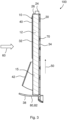
Figures 4 to 6 , at least onepart 15 of the at least onefilter medium body 12, 13 is tiltable about atilt axis 16 against a through-flow direction 60 of thefilter element 10 providing a bypass channel for the fluid flow. Thetilt axis 16 is parallel to theinstallation frame 30. In this embodiment, the bypass channel opens at the bottom of thefilter element 10 when the filter medium body 13 is in a tilted position. -
Figure 4 depicts the ambientair filter device 100 according toFigure 1 with part of thefilter element 10 tilted.Figure 5 depicts the ambientair filter device 100 with part of the filter element tilted in a rear view, whereas inFigure 6 the ambient air filter device is shown in a section view according to section plane A-A inFigure 5 . - If the
filter medium body 12 includes apleated medium 14, thetilt axis 16 may lie advantageously parallel one of the pleats of thefilter medium body 12, in particular in one of the pleats of thefilter medium body 12. Thus, thefilter element 10 may easily be tilted about thetilt axis 16. - According to a further favorable embodiment, the
filter element 10 may include at least two filtermedium bodies 12, 13, wherein at least one of the two filtermedium bodies 12, 13 is tiltable about thetilt axis 16 against a through-flow direction 60 of thefilter element 10. The other one of the filtermedium bodies 12, 13 may remain parallel to theinstallation frame 30. - The at least two filter
medium bodies 12, 13 may be joined together by a side band and/or a hinge, in particular a plastics hinge. Thus, the tilt movement of the two filtermedium bodies 12, 13 against each other may easily be achieved. - The
installation frame 30 includes twoend stop elements 42 on both sides of theinstallation frame 30, configured to limit a tilt movement of the at least onetiltable part 15 of the at least onefilter medium body 12, 13. The end stopelements 42 are arranged as a prolongation of theend guiding members 40 and limit the tilt movement of thefilter element 10 against the through-flow direction 60. - The end stop 80 at the lower part of the
installation frame 30 is configured as another flow-througharea 38 for air bypassing the at least onetiltable part 15 of the at least onefilter element 10. If thepart 15 of thefilter medium body 12 or, in the case of two filtermedium bodies 12, 13, one filter medium body 13 is tilted about thetilt axis 16, the other flow-througharea 38 is opened. Air may bypass thefilter element 10 in a bypass-flow direction 62 and may flow directly through the other flow-througharea 38 to the flow-througharea 36 of theinstallation frame 30. - The bypass may advantageously be opened if, e.g., critical thermal conditions of the battery of the vehicle are detected, in particular during fast charging of the battery.
-
- 10
- filter element
- 12
- filter medium body
- 13
- filter medium body
- 14
- filter medium
- 15
- part
- 16
- tilt axis
- 18
- side band
- 20
- side
- 22
- side
- 24
- sealing
- 26
- side
- 30
- installation frame
- 32
- air inlet side
- 34
- air outlet side
- 36
- flow-through area
- 38
- other flow-through area
- 40
- guiding member
- 42
- end stop element
- 50
- insertion direction
- 52
- fixing direction
- 60
- through-flow direction
- 62
- bypass-flow direction
- 70
- grid
- 80
- end stop
- 82
- protrusion
- 100
- ambient air filter device
Claims (11)
- An ambient air filter device (100) for arrangement in a front area of a vehicle, the ambient air filter device (100) comprising:an installation frame (30); anda filter element (10) arranged on the installation frame (30),wherein the installation frame (30) comprises a flow-through area (36) through which a fluid flow passing through the filter element (10) can pass, and at least one guiding member (40) arranged on opposing sides of the flow-through area (36) and for mounting the filter element (10) along an insertion direction (50), andwherein the filter element (10) comprises at least one filter medium body (12, 13) having at least one part (15) tiltable about a tilt axis (16) against a through-flow direction (60) of the filter element (10) to provide a bypass channel for the fluid flow to bypass the filter element (10).
- The ambient air filter device (100) according to claim 1, wherein the at least one filter medium body (12, 13) comprises a pleated medium (14), and
wherein the tilt axis (16) lies substantially parallel to one of pleats of the pleated medium (14). - The ambient air filter device (100) according to claim 1 or 2, further comprising side bands (18) covering at least parts of opposing sides (20, 22) of the at least one filter medium body (12, 13).
- The ambient air filter device (100) according to any one of claims 1 to 3, further comprising a sealing (24) arranged at least on one side (26) of the at least one filter medium body (12, 13).
- The ambient air filter device (100) according to any one of claims 1 to 4, wherein the installation frame (30) further comprises at least one end stop element (42) for limiting a tilt movement of the at least one part (15) of the at least one filter medium body (12, 13).
- The ambient air filter device (100) according to any one of claims 1 to 5, wherein the filter element (10) comprises at least two filter medium bodies (12, 13), and
wherein at least one of the at least two filter medium bodies (12, 13) is tiltable about the tilt axis (16) against the through-flow direction (60) of the filter element (10) to provide the bypass channel for the fluid flow to bypass the filter element (10). - The ambient air filter device (100) according to claim 6, wherein the at least two filter medium bodies (12, 13) are joined together by a side band and/or a hinge.
- The ambient air filter device (100) according to any one of claims 1 to 7, wherein the insertion direction (50) is substantially perpendicular to the through-flow direction (60) of the filter element (10).
- The ambient air filter device (100) according to any one of claims 1 to 8, wherein the installation frame (30) comprises an end stop (80) arranged at a lower end in the insertion direction (50), the end stop (80) being for fixing the filter element (10) in an intended mounting position, and the end stop (80) comprising another flow-through area (38) through which the fluid flow bypassing the filter element (10) can pass.
- The ambient air filter device (100) according to any one of claims 1 to 9, wherein the installation frame (30) comprises a grid (70) through which the fluid flow passing through the filter element (10) can pass and on which the filter element (10) is arranged.
- A filter element (10) in the ambient air filter device (100) according to any one of claims 1 to 10, the filter element (10) comprising:an air inlet side (32) and an air outlet side (34) through which the fluid flow can pass to the installation frame (30); andthe at least one filter medium body (12, 13) having the at least one part (15) tiltable about the tilt axis (16) against the through-flow direction (60) of the filter element (10) to provide the bypass channel for the fluid flow to bypass the filter element (10).
Priority Applications (2)
| Application Number | Priority Date | Filing Date | Title |
|---|---|---|---|
| EP23215701.6A EP4570351B1 (en) | 2023-12-12 | 2023-12-12 | Ambient air filter device and filter element in ambient air filter device |
| CN202411818514.8A CN120132504A (en) | 2023-12-12 | 2024-12-11 | Ambient air filter device and filter element in an ambient air filter device |
Applications Claiming Priority (1)
| Application Number | Priority Date | Filing Date | Title |
|---|---|---|---|
| EP23215701.6A EP4570351B1 (en) | 2023-12-12 | 2023-12-12 | Ambient air filter device and filter element in ambient air filter device |
Publications (2)
| Publication Number | Publication Date |
|---|---|
| EP4570351A1 true EP4570351A1 (en) | 2025-06-18 |
| EP4570351B1 EP4570351B1 (en) | 2026-07-29 |
Family
ID=89190483
Family Applications (1)
| Application Number | Title | Priority Date | Filing Date |
|---|---|---|---|
| EP23215701.6A Active EP4570351B1 (en) | 2023-12-12 | 2023-12-12 | Ambient air filter device and filter element in ambient air filter device |
Country Status (2)
| Country | Link |
|---|---|
| EP (1) | EP4570351B1 (en) |
| CN (1) | CN120132504A (en) |
Citations (6)
| Publication number | Priority date | Publication date | Assignee | Title |
|---|---|---|---|---|
| US4963170A (en) * | 1989-12-04 | 1990-10-16 | Global Consumer Services, Inc. | Inflow and outflow HEPA vent filter for asbestos work areas |
| JP2005007361A (en) * | 2003-06-20 | 2005-01-13 | Denso Corp | Air filter |
| US20090139200A1 (en) * | 2007-11-30 | 2009-06-04 | Eurocopter | Turboengine air intake provided with a controlled filter system |
| DE102008013501A1 (en) | 2008-03-10 | 2009-11-19 | Carl Freudenberg Kg | Filter element for use as fine dust filter element in e.g. air circulation system, of motor vehicle, has folding bellows containing filtering medium, and undercuts formed on side of closure element, where side is turned towards bellows |
| US20140123621A1 (en) * | 2012-11-08 | 2014-05-08 | Donaldson Company, Inc. | Actuated bypass hood for gas turbine air inlet system and methods |
| KR20140147553A (en) | 2013-06-20 | 2014-12-30 | 손동욱 | Apparatus for collecting particulate in air using vehicle |
-
2023
- 2023-12-12 EP EP23215701.6A patent/EP4570351B1/en active Active
-
2024
- 2024-12-11 CN CN202411818514.8A patent/CN120132504A/en active Pending
Patent Citations (6)
| Publication number | Priority date | Publication date | Assignee | Title |
|---|---|---|---|---|
| US4963170A (en) * | 1989-12-04 | 1990-10-16 | Global Consumer Services, Inc. | Inflow and outflow HEPA vent filter for asbestos work areas |
| JP2005007361A (en) * | 2003-06-20 | 2005-01-13 | Denso Corp | Air filter |
| US20090139200A1 (en) * | 2007-11-30 | 2009-06-04 | Eurocopter | Turboengine air intake provided with a controlled filter system |
| DE102008013501A1 (en) | 2008-03-10 | 2009-11-19 | Carl Freudenberg Kg | Filter element for use as fine dust filter element in e.g. air circulation system, of motor vehicle, has folding bellows containing filtering medium, and undercuts formed on side of closure element, where side is turned towards bellows |
| US20140123621A1 (en) * | 2012-11-08 | 2014-05-08 | Donaldson Company, Inc. | Actuated bypass hood for gas turbine air inlet system and methods |
| KR20140147553A (en) | 2013-06-20 | 2014-12-30 | 손동욱 | Apparatus for collecting particulate in air using vehicle |
Also Published As
| Publication number | Publication date |
|---|---|
| EP4570351B1 (en) | 2026-07-29 |
| CN120132504A (en) | 2025-06-13 |
Similar Documents
| Publication | Publication Date | Title |
|---|---|---|
| US9097466B2 (en) | Heat exchanger | |
| US4440555A (en) | Engine compartment and air cleaner | |
| US5213596A (en) | Air cleaner device | |
| EP1977812B1 (en) | Air cleaner unit for internal combustion engine | |
| EP1995103A1 (en) | Cooling module | |
| US20080017138A1 (en) | Cooling System | |
| CN114843665A (en) | Battery degassing unit and battery case | |
| CN101589220B (en) | Air cleaner unit for internal combustion engine | |
| CN110289751A (en) | power conversion device | |
| US20040083747A1 (en) | Air-conditioning system for vehicles | |
| JP2001132563A (en) | Intake system | |
| CN103770630A (en) | Mounting part for body attachment parts in the automotive field, and a mounting arrangement having a mounting part of said type | |
| JP2007084061A (en) | Heating, ventilation or air-conditioning unit improved with acoustic characteristic | |
| EP2078629B1 (en) | Cover for an air filter, in particular for a motor vehicle. | |
| US20120111197A1 (en) | Filter rack, filter assembly, and method of filtering air | |
| US6217439B1 (en) | Climate control unit | |
| CN120132504A (en) | Ambient air filter device and filter element in an ambient air filter device | |
| JP2006214440A (en) | Bypass valve for controlling flow rate of fluid, fluid filter constructed with including bypass valve, medium pack used for fluid filter, method for filtering fluid and filter system for fluid | |
| US11583795B2 (en) | Fastening module and filter system | |
| WO2017031264A1 (en) | Heat exchanger and manufacturing method | |
| EP4570352A1 (en) | Ambient air filter device and filter element in ambient air filter device | |
| EP1600624B1 (en) | Integrated air inlet module and its manufacturing process | |
| KR20260018037A (en) | Latchable filter insert in housing cover with support element for filter media body | |
| US20190170452A1 (en) | Heating or air conditioning system | |
| JP3846718B2 (en) | Ion exchange resin unit |
Legal Events
| Date | Code | Title | Description |
|---|---|---|---|
| PUAI | Public reference made under article 153(3) epc to a published international application that has entered the european phase |
Free format text: ORIGINAL CODE: 0009012 |
|
| STAA | Information on the status of an ep patent application or granted ep patent |
Free format text: STATUS: THE APPLICATION HAS BEEN PUBLISHED |
|
| AK | Designated contracting states |
Kind code of ref document: A1 Designated state(s): AL AT BE BG CH CY CZ DE DK EE ES FI FR GB GR HR HU IE IS IT LI LT LU LV MC ME MK MT NL NO PL PT RO RS SE SI SK SM TR |
|
| STAA | Information on the status of an ep patent application or granted ep patent |
Free format text: STATUS: REQUEST FOR EXAMINATION WAS MADE |
|
| 17P | Request for examination filed |
Effective date: 20251210 |
|
| GRAP | Despatch of communication of intention to grant a patent |
Free format text: ORIGINAL CODE: EPIDOSNIGR1 |
|
| STAA | Information on the status of an ep patent application or granted ep patent |
Free format text: STATUS: GRANT OF PATENT IS INTENDED |
|
| RIC1 | Information provided on ipc code assigned before grant |
Ipc: B01D 46/00 20220101AFI20260218BHEP Ipc: B01D 46/10 20060101ALI20260218BHEP Ipc: B01D 46/52 20060101ALI20260218BHEP |
|
| INTG | Intention to grant announced |
Effective date: 20260303 |
|
| GRAS | Grant fee paid |
Free format text: ORIGINAL CODE: EPIDOSNIGR3 |
|
| GRAA | (expected) grant |
Free format text: ORIGINAL CODE: 0009210 |
|
| STAA | Information on the status of an ep patent application or granted ep patent |
Free format text: STATUS: THE PATENT HAS BEEN GRANTED |
|
| AK | Designated contracting states |
Kind code of ref document: B1 Designated state(s): AL AT BE BG CH CY CZ DE DK EE ES FI FR GB GR HR HU IE IS IT LI LT LU LV MC ME MK MT NL NO PL PT RO RS SE SI SK SM TR |
|
| REG | Reference to a national code |
Ref country code: CH Ref legal event code: F10 Free format text: ST27 STATUS EVENT CODE: U-0-0-F10-F00 (AS PROVIDED BY THE NATIONAL OFFICE) Effective date: 20260729 |
|
| REG | Reference to a national code |
Ref country code: DE Ref legal event code: R096 Ref document number: 602023020445 Country of ref document: DE |