EP4570331A1 - Ball positioning and design recognition machine - Google Patents
Ball positioning and design recognition machine Download PDFInfo
- Publication number
- EP4570331A1 EP4570331A1 EP23383276.5A EP23383276A EP4570331A1 EP 4570331 A1 EP4570331 A1 EP 4570331A1 EP 23383276 A EP23383276 A EP 23383276A EP 4570331 A1 EP4570331 A1 EP 4570331A1
- Authority
- EP
- European Patent Office
- Prior art keywords
- ball
- valve
- recognition
- design
- balls
- Prior art date
- Legal status (The legal status is an assumption and is not a legal conclusion. Google has not performed a legal analysis and makes no representation as to the accuracy of the status listed.)
- Withdrawn
Links
Images
Classifications
-
- A—HUMAN NECESSITIES
- A63—SPORTS; GAMES; AMUSEMENTS
- A63B—APPARATUS FOR PHYSICAL TRAINING, GYMNASTICS, SWIMMING, CLIMBING, OR FENCING; BALL GAMES; TRAINING EQUIPMENT
- A63B45/00—Apparatus or methods for manufacturing balls
-
- A—HUMAN NECESSITIES
- A63—SPORTS; GAMES; AMUSEMENTS
- A63B—APPARATUS FOR PHYSICAL TRAINING, GYMNASTICS, SWIMMING, CLIMBING, OR FENCING; BALL GAMES; TRAINING EQUIPMENT
- A63B41/00—Hollow inflatable balls
- A63B41/12—Tools or devices for blowing up or closing balls
-
- A—HUMAN NECESSITIES
- A63—SPORTS; GAMES; AMUSEMENTS
- A63B—APPARATUS FOR PHYSICAL TRAINING, GYMNASTICS, SWIMMING, CLIMBING, OR FENCING; BALL GAMES; TRAINING EQUIPMENT
- A63B45/00—Apparatus or methods for manufacturing balls
- A63B45/02—Marking of balls
-
- A—HUMAN NECESSITIES
- A63—SPORTS; GAMES; AMUSEMENTS
- A63B—APPARATUS FOR PHYSICAL TRAINING, GYMNASTICS, SWIMMING, CLIMBING, OR FENCING; BALL GAMES; TRAINING EQUIPMENT
- A63B47/00—Devices for handling or treating balls, e.g. for holding or carrying balls
- A63B47/008—Devices for measuring or verifying ball characteristics
-
- A—HUMAN NECESSITIES
- A63—SPORTS; GAMES; AMUSEMENTS
- A63B—APPARATUS FOR PHYSICAL TRAINING, GYMNASTICS, SWIMMING, CLIMBING, OR FENCING; BALL GAMES; TRAINING EQUIPMENT
- A63B2220/00—Measuring of physical parameters relating to sporting activity
- A63B2220/05—Image processing for measuring physical parameters
-
- A—HUMAN NECESSITIES
- A63—SPORTS; GAMES; AMUSEMENTS
- A63B—APPARATUS FOR PHYSICAL TRAINING, GYMNASTICS, SWIMMING, CLIMBING, OR FENCING; BALL GAMES; TRAINING EQUIPMENT
- A63B2220/00—Measuring of physical parameters relating to sporting activity
- A63B2220/10—Positions
- A63B2220/13—Relative positions
-
- A—HUMAN NECESSITIES
- A63—SPORTS; GAMES; AMUSEMENTS
- A63B—APPARATUS FOR PHYSICAL TRAINING, GYMNASTICS, SWIMMING, CLIMBING, OR FENCING; BALL GAMES; TRAINING EQUIPMENT
- A63B2220/00—Measuring of physical parameters relating to sporting activity
- A63B2220/80—Special sensors, transducers or devices therefor
- A63B2220/801—Contact switches
-
- A—HUMAN NECESSITIES
- A63—SPORTS; GAMES; AMUSEMENTS
- A63B—APPARATUS FOR PHYSICAL TRAINING, GYMNASTICS, SWIMMING, CLIMBING, OR FENCING; BALL GAMES; TRAINING EQUIPMENT
- A63B2220/00—Measuring of physical parameters relating to sporting activity
- A63B2220/80—Special sensors, transducers or devices therefor
- A63B2220/806—Video cameras
-
- A—HUMAN NECESSITIES
- A63—SPORTS; GAMES; AMUSEMENTS
- A63B—APPARATUS FOR PHYSICAL TRAINING, GYMNASTICS, SWIMMING, CLIMBING, OR FENCING; BALL GAMES; TRAINING EQUIPMENT
- A63B2220/00—Measuring of physical parameters relating to sporting activity
- A63B2220/80—Special sensors, transducers or devices therefor
- A63B2220/807—Photo cameras
-
- A—HUMAN NECESSITIES
- A63—SPORTS; GAMES; AMUSEMENTS
- A63B—APPARATUS FOR PHYSICAL TRAINING, GYMNASTICS, SWIMMING, CLIMBING, OR FENCING; BALL GAMES; TRAINING EQUIPMENT
- A63B2225/00—Miscellaneous features of sport apparatus, devices or equipment
- A63B2225/05—Miscellaneous features of sport apparatus, devices or equipment with suction cups
- A63B2225/055—Miscellaneous features of sport apparatus, devices or equipment with suction cups used for fixing
-
- A—HUMAN NECESSITIES
- A63—SPORTS; GAMES; AMUSEMENTS
- A63B—APPARATUS FOR PHYSICAL TRAINING, GYMNASTICS, SWIMMING, CLIMBING, OR FENCING; BALL GAMES; TRAINING EQUIPMENT
- A63B2243/00—Specific ball sports not provided for in A63B2102/00 - A63B2102/38
- A63B2243/0025—Football
Definitions
- the present invention relates to a ball positioning machine, whose obvious purpose is to place balls in the precise place based on the location of the valve, which also performs design pattern recognition through the use of hydraulic cylinders that rotate the ball on the three three-dimensional axes in combination with three recognition chambers of the valve, the antipodal part of the valve and the recognition of the specific design of the ball.
- the object of the invention is to improve both the accuracy in the placement or positioning of balls, and the yield in their fast placement in a correct positioning, reducing the economical cost required in the process.
- the yield is rather low, because a long placement time is used and the specific design of balls is not checked, sometimes allowing the designs to be defective and be considered a defective ball to be sold at a lower cost.
- This machine has no background of the invention, as the only thing it has in common with previous inventions would be the automatic filling of balls, but not their positioning, which it is always carried out.
- the aim is to achieve the correct positioning and revision of design patterns at the same time time as allowing for filling by means of other machines for this purpose.
- the proposed ball positioning machine has been conceived to solve the above-mentioned problems, dramatically improving both precision and yield in the placement of balls to be filled, compared to manual processes or methods, reducing the working time of users with a substantial improvement in the quality of work and with the consequent economic benefit.
- the invention machine is made up of a working surface or frame where the pusher cylinder, located on the lower plane of the frame, vertically lifts the ball, that can be introduced manually or by means of an automated self-loading feeder, through a hole where a sensor detects the ball.
- This movement is given through rollers, improving the sliding movement, taking it to the receiving place where the search and positioning system of the ball starts to to be executed.
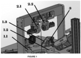
- elements 1 ( Figure 1 ) act at the same time holding the ball by means sliding elements that allow it to move freely without being thrown away.
- servomotors (elements 2 in Figure 1 ) arranged in an upper arc on the frame also to be adjusted to the ball through O-rings, and so that they can carry out very fast vertical, horizontal and lateral turning movements, which help in the search of the valve during such turns by means of a chamber (element 3 in Figure 1 ) that uses specific software (named HALCON), to locate both the valve, recognize the design pattern and locate the antipodal part of the valve through design pattern recognition.
- HALCON specific software
- the rotation of the ball is driven after the actuation of servomotors that exert a precise pressure to rotate the ball quickly until the chamber has detected the valve.
- the chamber (element 3 in Figure 1 ) is the one that detects the valve position, while the hexagonal pattern that matches the ball and also allows locating the opposite pole of the valve is detected.
- the ball is held in place by a suction cup which is vacuum-actuated and the deviation of the movement transfer is corrected using the reference hexagonal pattern.
- the chamber is controlled with Halcon software, through algorithms that act on valve search, pattern recognition and location opposite the valve, which cannot be the object of this invention.
- the described ball positioning machine is designed to place balls in the precise place based on the location of the valve and it recognizes design patterns and is characterized because it is made up of a frame with three sliding elements (1.1, 1.2 and 1.3) and an upper arc structure where servomotors (2.1 and 2.2) are located which rotate the ball in lateral, vertical and horizontal turns in combination with the recognition chamber (3.1) of the valve, the antipodal part of the valve and the recognition of the specific design of the ball.
Landscapes
- Health & Medical Sciences (AREA)
- General Health & Medical Sciences (AREA)
- Physical Education & Sports Medicine (AREA)
- Life Sciences & Earth Sciences (AREA)
- Biophysics (AREA)
- Display Devices Of Pinball Game Machines (AREA)
Abstract
Ball positioning machine intended for placing balls in the precise place based on the location of the valve and which recognizes design patterns, made up of a frame with three sliding elements and a upper arc structure where servomotors are located which rotate the ball in lateral, vertical and horizontal turns in combination with the recognition chamber of the valve, the antipodal part of the valve and the recognition of the specific design of the ball.
Description
- The present invention relates to a ball positioning machine, whose obvious purpose is to place balls in the precise place based on the location of the valve, which also performs design pattern recognition through the use of hydraulic cylinders that rotate the ball on the three three-dimensional axes in combination with three recognition chambers of the valve, the antipodal part of the valve and the recognition of the specific design of the ball.
- The object of the invention is to improve both the accuracy in the placement or positioning of balls, and the yield in their fast placement in a correct positioning, reducing the economical cost required in the process.
- Conventionally, the placement and positioning of balls is carried out manually by operators, requiring a considerable amount of time and balls are levelled using rather rudimentary methods, that even sometimes do not detect errors in the design of balls and which fall outside the tolerance established for this purpose in many regulations on the admissible shapes of balls in many sports competitions.
- In addition to the inaccuracy of the manual method or procedure of placement of balls, the yield is rather low, because a long placement time is used and the specific design of balls is not checked, sometimes allowing the designs to be defective and be considered a defective ball to be sold at a lower cost.
- This machine has no background of the invention, as the only thing it has in common with previous inventions would be the automatic filling of balls, but not their positioning, which it is always carried out. In this invention, the aim is to achieve the correct positioning and revision of design patterns at the same time time as allowing for filling by means of other machines for this purpose.
- The proposed ball positioning machine has been conceived to solve the above-mentioned problems, dramatically improving both precision and yield in the placement of balls to be filled, compared to manual processes or methods, reducing the working time of users with a substantial improvement in the quality of work and with the consequent economic benefit.
- More specifically, the invention machine is made up of a working surface or frame where the pusher cylinder, located on the lower plane of the frame, vertically lifts the ball, that can be introduced manually or by means of an automated self-loading feeder, through a hole where a sensor detects the ball. This movement is given through rollers, improving the sliding movement, taking it to the receiving place where the search and positioning system of the ball starts to to be executed. In this phase, elements 1 (
Figure 1 ) act at the same time holding the ball by means sliding elements that allow it to move freely without being thrown away. This allows servomotors (elements 2 inFigure 1 ) arranged in an upper arc on the frame also to be adjusted to the ball through O-rings, and so that they can carry out very fast vertical, horizontal and lateral turning movements, which help in the search of the valve during such turns by means of a chamber (element 3 inFigure 1 ) that uses specific software (named HALCON), to locate both the valve, recognize the design pattern and locate the antipodal part of the valve through design pattern recognition. - The rotation of the ball is driven after the actuation of servomotors that exert a precise pressure to rotate the ball quickly until the chamber has detected the valve.
- When searching forthe valve, the chamber (
element 3 inFigure 1 ) is the one that detects the valve position, while the hexagonal pattern that matches the ball and also allows locating the opposite pole of the valve is detected. Once the valve position is determined, the ball is held in place by a suction cup which is vacuum-actuated and the deviation of the movement transfer is corrected using the reference hexagonal pattern. - The chamber is controlled with Halcon software, through algorithms that act on valve search, pattern recognition and location opposite the valve, which cannot be the object of this invention.
- In order to complement the above description and assist in a better understanding of the invention features, a figure with illustrative and non-limiting nature is attached hereto as an integral part of said description, showing a general perspective of the machine object of the invention with its elements indicated.
- Therefore, the described ball positioning machine is designed to place balls in the precise place based on the location of the valve and it recognizes design patterns and is characterized because it is made up of a frame with three sliding elements (1.1, 1.2 and 1.3) and an upper arc structure where servomotors (2.1 and 2.2) are located which rotate the ball in lateral, vertical and horizontal turns in combination with the recognition chamber (3.1) of the valve, the antipodal part of the valve and the recognition of the specific design of the ball.
Claims (1)
- Ball positioning machine intended for placing balls in the precise place based on the location of the valve and which recognizes design patterns, characterized because it is made up of a frame with three sliding elements (1.1, 1.2 and 1.3) and a upper arc structure where servomotors (2.1 and 2.2) are located which rotate the ball in lateral, vertical and horizontal turns in combination with the recognition chamber (3.1) of the valve, the antipodal part of the valve and the recognition of the specific design of the ball.
Priority Applications (1)
| Application Number | Priority Date | Filing Date | Title |
|---|---|---|---|
| EP23383276.5A EP4570331A1 (en) | 2023-12-12 | 2023-12-12 | Ball positioning and design recognition machine |
Applications Claiming Priority (1)
| Application Number | Priority Date | Filing Date | Title |
|---|---|---|---|
| EP23383276.5A EP4570331A1 (en) | 2023-12-12 | 2023-12-12 | Ball positioning and design recognition machine |
Publications (1)
| Publication Number | Publication Date |
|---|---|
| EP4570331A1 true EP4570331A1 (en) | 2025-06-18 |
Family
ID=89473329
Family Applications (1)
| Application Number | Title | Priority Date | Filing Date |
|---|---|---|---|
| EP23383276.5A Withdrawn EP4570331A1 (en) | 2023-12-12 | 2023-12-12 | Ball positioning and design recognition machine |
Country Status (1)
| Country | Link |
|---|---|
| EP (1) | EP4570331A1 (en) |
Citations (5)
| Publication number | Priority date | Publication date | Assignee | Title |
|---|---|---|---|---|
| EP0215970B1 (en) * | 1985-09-23 | 1989-07-05 | Sumitomo Rubber Industries Limited | Method for positioning seamed balls |
| US5632205A (en) * | 1995-06-07 | 1997-05-27 | Acushnet Company | Apparatus for the spatial orientation and manipulation of a game ball |
| US7283657B1 (en) * | 2002-08-07 | 2007-10-16 | Carlson Ralph L | Method and system for automatically orienting a spherical object |
| US20150085046A1 (en) * | 2013-09-26 | 2015-03-26 | Heidelberger Druckmaschinen Ag | Machine for inkjet printing three-dimensional objects |
| US9688078B1 (en) * | 2016-03-10 | 2017-06-27 | Xerox Corporation | Method and apparatus for printing on a spherical object |
-
2023
- 2023-12-12 EP EP23383276.5A patent/EP4570331A1/en not_active Withdrawn
Patent Citations (5)
| Publication number | Priority date | Publication date | Assignee | Title |
|---|---|---|---|---|
| EP0215970B1 (en) * | 1985-09-23 | 1989-07-05 | Sumitomo Rubber Industries Limited | Method for positioning seamed balls |
| US5632205A (en) * | 1995-06-07 | 1997-05-27 | Acushnet Company | Apparatus for the spatial orientation and manipulation of a game ball |
| US7283657B1 (en) * | 2002-08-07 | 2007-10-16 | Carlson Ralph L | Method and system for automatically orienting a spherical object |
| US20150085046A1 (en) * | 2013-09-26 | 2015-03-26 | Heidelberger Druckmaschinen Ag | Machine for inkjet printing three-dimensional objects |
| US9688078B1 (en) * | 2016-03-10 | 2017-06-27 | Xerox Corporation | Method and apparatus for printing on a spherical object |
Similar Documents
| Publication | Publication Date | Title |
|---|---|---|
| US10031515B2 (en) | Production system including robot with position correction function that supplies or ejects workpieces to or from a machine tool | |
| CN104440384B (en) | A kind of method setting up workpiece numerical-controlled Cutter coordinate system | |
| CN105345281B (en) | Laser welding machine | |
| EP2503059B1 (en) | Automatic machine for leveling and alignment of ballastless railway, prior to concreting. | |
| EP3546118B1 (en) | Machining system and machining method | |
| US10792776B2 (en) | Machine tool and origin point correction method | |
| EP1251415A2 (en) | Method and apparatus for grinding eccentric cylindrical portions of workpiece with diameter measuring device | |
| CN201583445U (en) | Air-valve bending testing machine | |
| CN204472171U (en) | A kind of certificate feeding device of automatic stamping machine | |
| CN106112141B (en) | A kind of stainless steel fitting automatic tapping device | |
| CN102076459B (en) | Equipment and related operation method for correct centering of processed workpiece on fixture of vertical mandrel of machine tool | |
| EP0042012A1 (en) | Method for aligning an injection mold with a nozzle at the mold injection station | |
| KR102096740B1 (en) | Cam-set assembly Auto assembling apparatus for fuel pump of vehicle | |
| CN103056623B (en) | A kind of shift rod assembly processing method | |
| CN109859273B (en) | A Calibration Method of Online Dynamic Vision Processing System | |
| CN207358176U (en) | A kind of eccentric shaft parts machining eccentricity adjusts positioner | |
| JP2750967B2 (en) | Method and apparatus for centering a workpiece on a processing table of a turning machine | |
| CN105347022B (en) | A kind of workpiece sampler | |
| CN114986145B (en) | Press-fitting processing equipment and press-fitting processing method for output shaft | |
| CN204524735U (en) | An automatic lens locking machine | |
| CN104259511B (en) | The full automatic processing device of hole, a kind of band location bar and method thereof | |
| CN114871508B (en) | Correction and adjustment method for gear hobbing of integral crankshaft | |
| CN102501126A (en) | Tipper | |
| CN205765269U (en) | The detection device of wheel hub | |
| CN117840577A (en) | Riveting processing method, system, storage medium and intelligent terminal |
Legal Events
| Date | Code | Title | Description |
|---|---|---|---|
| PUAI | Public reference made under article 153(3) epc to a published international application that has entered the european phase |
Free format text: ORIGINAL CODE: 0009012 |
|
| STAA | Information on the status of an ep patent application or granted ep patent |
Free format text: STATUS: THE APPLICATION HAS BEEN PUBLISHED |
|
| AK | Designated contracting states |
Kind code of ref document: A1 Designated state(s): AL AT BE BG CH CY CZ DE DK EE ES FI FR GB GR HR HU IE IS IT LI LT LU LV MC ME MK MT NL NO PL PT RO RS SE SI SK SM TR |
|
| STAA | Information on the status of an ep patent application or granted ep patent |
Free format text: STATUS: THE APPLICATION IS DEEMED TO BE WITHDRAWN |
|
| 18D | Application deemed to be withdrawn |
Effective date: 20251219 |