EP4570295A2 - Blood collection devices, systems, and methods facilitating blood flashback - Google Patents
Blood collection devices, systems, and methods facilitating blood flashback Download PDFInfo
- Publication number
- EP4570295A2 EP4570295A2 EP25174238.3A EP25174238A EP4570295A2 EP 4570295 A2 EP4570295 A2 EP 4570295A2 EP 25174238 A EP25174238 A EP 25174238A EP 4570295 A2 EP4570295 A2 EP 4570295A2
- Authority
- EP
- European Patent Office
- Prior art keywords
- needle hub
- needle
- channel
- catheter
- catheter system
- Prior art date
- Legal status (The legal status is an assumption and is not a legal conclusion. Google has not performed a legal analysis and makes no representation as to the accuracy of the status listed.)
- Pending
Links
Images









Classifications
-
- A—HUMAN NECESSITIES
- A61—MEDICAL OR VETERINARY SCIENCE; HYGIENE
- A61B—DIAGNOSIS; SURGERY; IDENTIFICATION
- A61B5/00—Measuring for diagnostic purposes; Identification of persons
- A61B5/15—Devices for taking samples of blood
- A61B5/150992—Blood sampling from a fluid line external to a patient, such as a catheter line, combined with an infusion line; Blood sampling from indwelling needle sets, e.g. sealable ports, luer couplings or valves
-
- A—HUMAN NECESSITIES
- A61—MEDICAL OR VETERINARY SCIENCE; HYGIENE
- A61M—DEVICES FOR INTRODUCING MEDIA INTO, OR ONTO, THE BODY; DEVICES FOR TRANSDUCING BODY MEDIA OR FOR TAKING MEDIA FROM THE BODY; DEVICES FOR PRODUCING OR ENDING SLEEP OR STUPOR
- A61M25/00—Catheters; Hollow probes
- A61M25/0097—Catheters; Hollow probes characterised by the hub
-
- A—HUMAN NECESSITIES
- A61—MEDICAL OR VETERINARY SCIENCE; HYGIENE
- A61M—DEVICES FOR INTRODUCING MEDIA INTO, OR ONTO, THE BODY; DEVICES FOR TRANSDUCING BODY MEDIA OR FOR TAKING MEDIA FROM THE BODY; DEVICES FOR PRODUCING OR ENDING SLEEP OR STUPOR
- A61M25/00—Catheters; Hollow probes
- A61M25/01—Introducing, guiding, advancing, emplacing or holding catheters
- A61M25/06—Body-piercing guide needles or the like
- A61M25/0606—"Over-the-needle" catheter assemblies, e.g. I.V. catheters
-
- A—HUMAN NECESSITIES
- A61—MEDICAL OR VETERINARY SCIENCE; HYGIENE
- A61M—DEVICES FOR INTRODUCING MEDIA INTO, OR ONTO, THE BODY; DEVICES FOR TRANSDUCING BODY MEDIA OR FOR TAKING MEDIA FROM THE BODY; DEVICES FOR PRODUCING OR ENDING SLEEP OR STUPOR
- A61M25/00—Catheters; Hollow probes
- A61M25/01—Introducing, guiding, advancing, emplacing or holding catheters
- A61M25/06—Body-piercing guide needles or the like
- A61M25/0612—Devices for protecting the needle; Devices to help insertion of the needle, e.g. wings or holders
- A61M25/0618—Devices for protecting the needle; Devices to help insertion of the needle, e.g. wings or holders having means for protecting only the distal tip of the needle, e.g. a needle guard
- A61M25/0625—Devices for protecting the needle; Devices to help insertion of the needle, e.g. wings or holders having means for protecting only the distal tip of the needle, e.g. a needle guard with a permanent connection to the needle hub, e.g. a guiding rail, a locking mechanism or a guard advancement mechanism
-
- A—HUMAN NECESSITIES
- A61—MEDICAL OR VETERINARY SCIENCE; HYGIENE
- A61M—DEVICES FOR INTRODUCING MEDIA INTO, OR ONTO, THE BODY; DEVICES FOR TRANSDUCING BODY MEDIA OR FOR TAKING MEDIA FROM THE BODY; DEVICES FOR PRODUCING OR ENDING SLEEP OR STUPOR
- A61M25/00—Catheters; Hollow probes
- A61M25/01—Introducing, guiding, advancing, emplacing or holding catheters
- A61M25/06—Body-piercing guide needles or the like
- A61M25/0693—Flashback chambers
-
- A—HUMAN NECESSITIES
- A61—MEDICAL OR VETERINARY SCIENCE; HYGIENE
- A61M—DEVICES FOR INTRODUCING MEDIA INTO, OR ONTO, THE BODY; DEVICES FOR TRANSDUCING BODY MEDIA OR FOR TAKING MEDIA FROM THE BODY; DEVICES FOR PRODUCING OR ENDING SLEEP OR STUPOR
- A61M39/00—Tubes, tube connectors, tube couplings, valves, access sites or the like, specially adapted for medical use
- A61M39/10—Tube connectors; Tube couplings
-
- A—HUMAN NECESSITIES
- A61—MEDICAL OR VETERINARY SCIENCE; HYGIENE
- A61M—DEVICES FOR INTRODUCING MEDIA INTO, OR ONTO, THE BODY; DEVICES FOR TRANSDUCING BODY MEDIA OR FOR TAKING MEDIA FROM THE BODY; DEVICES FOR PRODUCING OR ENDING SLEEP OR STUPOR
- A61M5/00—Devices for bringing media into the body in a subcutaneous, intra-vascular or intramuscular way; Accessories therefor, e.g. filling or cleaning devices, arm-rests
- A61M5/178—Syringes
- A61M5/31—Details
- A61M2005/3112—Incorporating self-aspirating means, e.g. to provide flashback
-
- A—HUMAN NECESSITIES
- A61—MEDICAL OR VETERINARY SCIENCE; HYGIENE
- A61M—DEVICES FOR INTRODUCING MEDIA INTO, OR ONTO, THE BODY; DEVICES FOR TRANSDUCING BODY MEDIA OR FOR TAKING MEDIA FROM THE BODY; DEVICES FOR PRODUCING OR ENDING SLEEP OR STUPOR
- A61M39/00—Tubes, tube connectors, tube couplings, valves, access sites or the like, specially adapted for medical use
- A61M39/10—Tube connectors; Tube couplings
- A61M2039/1077—Adapters, e.g. couplings adapting a connector to one or several other connectors
Definitions
- Intravenous catheters are commonly used for a variety of infusion therapies.
- intravenous catheters may be used for infusing fluids, such as normal saline solution, various medicaments, and total parenteral nutrition, into a patient.
- Intravenous catheters may also be used for withdrawing blood from the patient.
- Intravenous catheters may include "over-the needle” catheters, which may be mounted over a needle having a sharp distal tip. The sharp distal tip may be used to pierce skin and the vasculature of the patient. Insertion of the intravenous catheter into the vasculature may follow the piercing of the vasculature by the needle.
- the needle and the intravenous catheter are generally inserted at a shallow angle through the skin into the vasculature of the patient with a bevel of the needle facing up and away from the skin of the patient.
- the introducer needle may include a notch disposed towards a distal end of the introducer needle, and in response to the distal tip of the introducer needle being positioned within the vasculature, blood may flow proximally through a needle lumen, exit the needle lumen through the notch, and then travel proximally between an outer surface of the introducer needle and an inner surface of the intravenous catheter.
- the user may visualize a small amount of blood "flashback" and thereby confirm placement of the intravenous catheter within the vasculature. Presence of a vasculature entrance indicator, such as flashback, may facilitate successful placement of intravenous catheters. Once placement of the introducer needle within the vasculature has been confirmed, the user may temporarily occlude flow in the vasculature and withdraw the introducer needle, leaving the intravenous catheter in place for future blood withdrawal and/or fluid infusion.
- a vasculature entrance indicator such as flashback
- a catheter system may include a catheter adapter which may include a distal end, a proximal end, and a lumen extending through the distal end and the proximal end.
- the catheter system may include a catheter extending distally from the distal end of the catheter adapter.
- the catheter system may include a needle hub, which may include a distal end and a proximal end. In some embodiments, the distal end of the needle hub may be coupled to the proximal end of the catheter adapter.
- the catheter system may include a peripheral intravenous catheter system, such as, for example, the BD NEXIVA TM Closed IV Catheter system, the BD CATHENA TM Catheter system, the BD VENFLON TM Pro Safely Shielded IV Catheter system, the BD NEOFLON TM IV Cannula system, the BD INSYTE TM AUTOGUARD TM BC Shielded IV Catheter system, or another suitable peripheral intravenous catheter system.
- the catheter system may include a PICC system or a midline catheter system.
- the catheter system may include a needle, which may include a distal end and a proximal end.
- the needle may include an introducer needle, which may include a sharp distal tip.
- the needle may be secured within the needle hub.
- the catheter system may include a flow control plug, which may be coupled to the proximal end of the needle hub.
- the flow control plug may block a proximal opening of the needle hub such that blood does not exit the proximal opening of the needle hub.
- the flow control plug may include one or more vents, which may include a porous membrane or microgrooves that may vent air while containing blood.
- the catheter system may include a flashback pathway disposed between an outer surface of the flow control plug and an inner surface of the needle hub.
- the needle hub may be constructed of a clear or transparent material, which may facilitate observation blood within the flashback pathway.
- the needle hub may include a lens, which may facilitate observation of blood within the flashback pathway.
- the flow control plug may be constructed of a white material, which may provide a sharp contrast when blood flows into the flashback pathway.
- the outer surface of the flow control plug may include a channel.
- the flashback pathway may extend through the channel between the channel and the inner surface of the needle hub.
- the channel may provide a high area-to-volume ratio and may include a small height compared to its width.
- a velocity of blood travelling within the channel may be between 1 mm/s and 2 mm/s.
- a velocity of blood travelling within the channel may between 0.22 mm/s and 2 mm/s, which may create a continuous motion indicative of vein access in a real-time or near real-time manner.
- it may take greater than 1 s for blood to move from one end of the channel to the other. For example, it may take between 5 s and 20 s for blood to move through the channel.
- the flashback pathway may provide an unobstructed, sharp-contrast visualization of a small volume of blood.
- the catheter system may provide an effective signal for vein confirmation with a small amount of blood, such as approximately 10 mL.
- the channel may be disposed on a top of the flow control plug, as illustrated, for example, in Figure 1A , to ease visibility of the flashback pathway.
- the outer surface of the flow control plug may include a pocket proximate the channel.
- the proximal end of the needle may be disposed within the pocket.
- the pocket may be deeper than the channel. Blood travelling through the flashback pathway may be forced from the pocket to an outside of the flow control plug, which may improve visibility of the blood within the flashback pathway to the clinician.
- the channel may be formed by multiple side walls, which may extend from a bottom of the channel to the inner surface of the needle hub and may contact the inner surface of the needle hub.
- blood may be contained within the channel as it travels proximally through the channel.
- the vent may be disposed proximate the channel, such as at a proximal end of the channel. In some embodiments, the vent may be disposed at an interface between the proximal end of the needle hub and the flow control plug.
- the distal end of the flow control plug may include a male luer.
- the male luer may include a slip male luer or a threaded male luer.
- a tip of the male luer may include a generally planar surface, which may extend across the tip such that a shape of the flashback pathway is generally semi-circular.
- the outer surface of the flow control plug may include multiple channels, and the flashback pathway may extend through the channels between the channels and the inner surface of the needle hub.
- the outer surface of the flow control plug may include one or more grooves extending from the channels inwardly towards a longitudinal axis of the flow control plug.
- a proximal end of each of the channels may be formed by a proximal wall.
- the proximal wall may include one or more microgrooves configured to allow air but not blood to pass.
- the proximal wall may interfere with an inner surface of the needle hub, which may prevent blood from exiting the proximal end of the channel.
- a catheter assembly of the catheter system may include the catheter adapter and the catheter.
- a needle assembly of the catheter system may include one or more of the following: the needle hub, the needle, an inner barrel, and an outer barrel.
- the inner barrel may surround the needle hub.
- the needle hub may be secured within the inner barrel.
- the flashback pathway may be disposed between an outer surface of the needle hub and an inner surface of the inner barrel.
- the flow control plug may be constructed of a white material, which may provide a sharp contrast when blood flows into the flashback pathway.
- the outer barrel may surround the inner barrel.
- the inner barrel and the needle hub may be configured to move proximally within the outer barrel to retract the needle.
- the needle assembly may include a button and/or a spring.
- the inner barrel and the needle hub may move proximally within the outer barrel in response to depression of the button and actuation of the spring.
- the needle hub may include a channel, and the flashback pathway may extend through the channel between the channel and the inner surface of the inner barrel.
- the needle hub may include a pocket proximate the channel.
- the proximal end of the needle may be disposed within the pocket.
- the pocket may be deeper than the channel.
- a proximal end of the channel may be formed by a proximal wall of the needle hub.
- the proximal wall may include one or more microgrooves configured to allow air but not blood to pass.
- the proximal wall may interfere with an inner surface of the inner barrel.
- the inner surface of the inner barrel may include one or more alignment ridges.
- the outer surface of the needle hub may include one or more other alignment ridges, which may contact the alignment ridges.
- the needle assembly may include a middle barrel.
- the inner barrel may include a hole and/or the middle barrel may include a hole aligned with the hole of the inner barrel.
- the flashback pathway may include the first hole and the second hole and may extend between an outer surface of the middle barrel and an inner surface of the outer barrel.
- the pocket may be proximate the first hole.
- the inner barrel and the needle hub may be configured to move proximally within the middle barrel to retract the needle.
- the inner barrel and the needle hub may move proximally in response to depression of the button and actuation of the spring.
- a catheter system 10 may include a catheter adapter 12 which may include a distal end 14, a proximal end 16, and a lumen 18 extending through the distal end 14 and the proximal end 16.
- the catheter system 10 may include a catheter 20 extending distally from the distal end 14 of the catheter adapter 12.
- the catheter system 10 may include a needle hub 22, which may include a distal end 24 and a proximal end 26.
- the distal end 24 of the needle hub 22 may be coupled to the proximal end 26 of the catheter adapter 12.
- the catheter system 10 may include a peripheral intravenous catheter system, such as, for example, the BD NEXIVA TM Closed IV Catheter system, the BD CATHENA TM Catheter system, the BD VENFLON TM Pro Safely Shielded IV Catheter system, the BD NEOFLON TM IV Cannula system, the BD INSYTE TM AUTOGUARD TM BC Shielded IV Catheter system, or another suitable peripheral intravenous catheter system.
- the catheter system 10 may include a PICC system or a midline catheter system.
- the catheter system 10 may include a needle 28 which may include a distal end 30 and a proximal end 32.
- the needle 28 may include an introducer needle, which may include a sharp distal tip.
- the needle 28 may be secured within the needle hub 22.
- the catheter system 10 may include a flow control plug 34, which may be coupled to the proximal end 26 of the needle hub 22.
- the flow control plug 34 may block a proximal opening 36 of the needle hub 22 such that blood does not exit the proximal opening 36 of the needle hub 22.
- the flow control plug 34 may include one or more vents 38, which may include a porous membrane or a microgroove that may vent air while containing blood.
- a cap 35 may be coupled to a proximal end of the flow control plug 34.
- the catheter system 10 may include a flashback pathway 40 disposed between an outer surface of the flow control plug 34 and an inner surface of the needle hub 22.
- the needle hub 22 may be constructed of a clear or transparent material, which may facilitate observation blood within the flashback pathway 40.
- the needle hub may include a lens 42, which may facilitate observation of blood within the flashback pathway 40.
- the flow control plug 34 may be constructed of a white material, which may provide a sharp contrast when blood flows into the flashback pathway 40.
- the lens 42 may be disposed above a proximal end 32 of the needle 28. In some embodiments, the lens 42 may be integrated within the needle hub 22. In some embodiments, the lens 42 may be convex or another suitable shape. In some embodiments, an outer surface of the lens 42 may generally conform to a shape of an outer surface of the needle hub 22.
- the outer surface of the flow control plug 34 may include a channel 44.
- the flashback pathway 40 may extend through the channel 44 between the channel 44 and the inner surface of the needle hub 22.
- the channel 44 may provide a high area-to-volume ratio and may include a small height compared to its width.
- a velocity of blood travelling within the channel 44 may be between 1 mm/s and 2 mm/s.
- a velocity of blood travelling within the channel 44 may between 0.22 mm/s and 2 mm/s, which may create a continuous motion indicative of vein access in a real-time or near real-time manner.
- the channel 44 may be axially aligned with a longitudinal axis of the catheter system 10.
- the flashback pathway 40 may provide an unobstructed, sharp-contrast visualization of a small volume of blood.
- the catheter system 10 may provide an effective signal for vein confirmation with a small amount of blood, such as approximately 10 mL.
- the channel 44 may be disposed on a top of the flow control plug 34, as illustrated, for example, in Figure 1A , to ease visibility of the flashback pathway 40.
- a bevel of the sharp distal tip of the needle 28 may face toward a top of the catheter system 10 when the catheter system 10 is in an insertion position, ready for insertion into a patient, as illustrated, for example, in Figure 1A .
- the outer surface of the flow control plug 34 may include a pocket 46 proximate the channel 44.
- the proximal end 32 of the needle 28 may be disposed within the pocket 46.
- the pocket 46 may be deeper than the channel 44. Blood travelling through the flashback pathway 40 may be forced from the pocket 46 to an outside of the flow control plug 34, which may improve visibility of the blood within the flashback pathway 40 to the clinician.
- the channel 44 may be formed by multiple side walls 48, which may extend from a bottom of the channel 44 to the inner surface of the needle hub 22 and may contact the inner surface of the needle hub 22. Thus, blood may be contained within the channel 44 as it travels proximally through the channel 44.
- the vents 38 may be disposed proximate the channel 44, such as at a proximal end of the channel 44. In some embodiments, the vents 38 may be disposed at an interface between the proximal end 26 of the needle hub 22 and the flow control plug 34.
- the side walls 48 may include elongated ribs. In some embodiments, a height of the side walls 48 from a bottom of the channel 44 and/or a width of the channel 44 from one of the side walls 48 to the an opposite of the side walls 48 may increase with an increased gauge size of the catheter 20.
- the flow control plug 34 illustrated in Figure 1D may be used with a larger gauge catheter than the flow control plug 34 illustrated in Figure 1C .
- the flow control plug 34 illustrated in Figure 3A may be used with a larger gauge catheter than the flow control plug 34 illustrated in Figures 1C and 1D .
- the distal end of the flow control plug 34 may include a male luer.
- the male luer may include a slip male luer or a threaded male luer.
- the outer surface of the flow control plug 34 may include multiple channels 44, and the flashback pathway 40 may extend through the channels 44 between the channels 44 and the inner surface of the needle hub 22. In some embodiments, a number of the channels 44 may vary. In some embodiments, the outer surface of the flow control plug 34 may include one or more grooves 50 extending from the channels 44 inwardly towards a longitudinal axis of the flow control plug 34. In some embodiments, the grooves 50 may be generally perpendicular to the channels 44.
- a proximal end of each of the channels 44 may be formed by a proximal wall 52.
- the proximal wall 52 may include one or more microgrooves configured to allow air but not blood to pass.
- the proximal wall 52 may interfere with an inner surface of the needle hub 22, which may prevent blood from exiting the proximal end of the channel 44.
- the needle hub 22 may be constructed of a clear or transparent material, which may facilitate observation blood within the flashback pathway 40.
- the needle hub 22 may include one or more lenses, which may facilitate observation of blood within the flashback pathway 40.
- the flow control plug 34 may be constructed of a white material, which may provide a sharp contrast when blood flows into the flashback pathway 40.
- a tip 54 of the male luer may include a generally planar surface 56, which may extend across the tip 54 such that a shape of the flashback pathway 40 is generally semi-circular.
- the flow control plug 34 illustrated in Figure 3A may be used with an 18 or 20 gauge catheter or another suitable size catheter.
- a catheter assembly 58 of a catheter system 60 may include the catheter adapter 12 and the catheter 20.
- the catheter system 60 may include or correspond to the catheter system 10 of one of more of Figures 1A-3C .
- a needle assembly 62 of the catheter system 60 may include one or more of the following: the needle hub 22, the needle 28, an inner barrel 64, and an outer barrel 66.
- the inner barrel 6 4 may surround the needle hub 22.
- the needle hub 22 may be secured within the inner barrel 64.
- the flashback pathway 40 may be disposed between an outer surface of the needle hub 22 and an inner surface of the inner barrel 64.
- the flow control plug 34 may be constructed of a white material, which may provide a sharp contrast when blood flows into the flashback pathway 40.
- the outer barrel 66 may surround the inner barrel 64.
- the inner barrel 64 and the needle hub 22 may be configured to move proximally within the outer barrel 66 to retract the needle 28.
- the needle assembly 62 may include a button 68 and/or a spring 70.
- the inner barrel 64 and the needle hub 22 may move proximally within the outer barrel 66 in response to depression of the button 68 and actuation of the spring 70.
- a needle retraction mechanism of the catheter system 60 may operate similar to the BD INSYTE TM AUTOGUARD TM BC Shielded IV Catheter System or another suitable catheter system.
- the inner barrel 64 may include a generally hour-glass shape so that its medial portion has a smaller diameter than either end. This shape facilitates engagement between an opening 71 in the button 68 and the inner barrel 64.
- a projection 73 may be located inside the catheter adapter 12. Thus, when the catheter 20 is still located on the needle 28 with the catheter adapter 12, the projection 73 may prevent the button 68 from being moved “down" into the activated position.
- the button 68 When the catheter 20 is moved off the needle 28 so the catheter adapter 12 is not adjacent to the projection 73, the button 68 may be moved "down," i.e. activated, because the catheter adapter 12 no longer interferes with the movement of the projection 73. In this position, the opening 71 is larger than a maximum diameter of inner barrel 64.
- the spring 70 can thus force the needle hub 22 and the inner barrel 64 to a proximal end of the outer barrel 66 and withdraw the the distal end 30 of the needle 28 into the outer barrel 66.
- the inner barrel 64 and the needle hub 22 may be integrally formed or monolithically formed as a single unit.
- the needle hub 22 may include a channel 44, and the flashback pathway 40 may extend through the channel 44 between the channel 44 and the inner surface of the inner barrel 64.
- the needle hub 22 may include a pocket 46 proximate the channel 44.
- the proximal end of the needle 28 may be disposed within the pocket 46.
- the pocket 46 may be deeper than the channel 44.
- a proximal end of the channel 44 may be formed by a proximal wall 52 of the needle hub 22.
- the proximal wall 52 may include one or more vents, which may include a microgroove configured to allow air but not blood to pass.
- the proximal wall 52 may interfere with an inner surface of the inner barrel 64.
- the inner surface of the inner barrel 64 may include one or more alignment ridges 74.
- the outer surface of the needle hub 22 may include one or more other alignment ridges 76, which may contact the alignment ridges 74 to facilitate orientation of the needle hub 22 with respect to the inner barrel 64.
- the needle assembly 62 may include a middle barrel 78.
- the inner barrel 64 may include a first hole 80 and/or the middle barrel 78 may include a second hole 82 aligned with the first hole 80 of the inner barrel 64.
- the flashback pathway 40 may include the first hole 80 and the second hole 82 and may extend between an outer surface of the middle barrel 78 and an inner surface of the outer barrel 66.
- a pocket 46 may be proximate the first hole 80.
- the inner barrel 64 and the needle hub 22 may be configured to move proximally within the middle barrel 78 to retract the needle 28.
- the inner barrel 64 and the needle hub 22 may move proximally in response to depression of the button 68 and actuation of the spring 70.
- the outer surface of the middle barrel 78 may include a channel 44, and the flashback pathway 40 may extend through the channel 44 between the channel 44 and the inner surface of the inner barrel 64.
- the needle hub 22 may include a pocket 46 proximate the channel 44.
- the proximal end 32 of the needle 28 may be disposed within the pocket 46.
- a proximal end of the channel 44 may be formed by a proximal wall 52 of the middle barrel 78.
- the proximal wall 52 may include one or more vents, which may each include a microgroove configured to allow air but not blood to pass.
- the proximal wall 52 may interfere with an inner surface of the outer barrel 66.
- the channel 44 may be formed by multiple side walls 48, which may extend from a bottom of the channel 44 to the inner surface of the outer barrel 66 and may contact the inner surface of the outer barrel 66. Thus, blood may be contained within the channel 44 as it travels proximally through the channel 44.
- the needle hub 22 is illustrated being inserted into the inner barrel 64 during assembly of a catheter system.
- the catheter system may include or correspond to the catheter system 60 of Figures 4A-4F and/or Figures 5A-5E .
- the proximal end 26 of the needle 28 may contact and be secured within the needle hub 22, but a remaining portion of the needle 28 may not contact the needle hub 22 and/or any portion of the catheter system.
- the proximal end 26 of the needle 28 may be pinched and/or glued within the needle hub 22, as illustrated, for example, in Figure 6B .
- the vents 38 may be disposed on a bottom of the needle hub 22, which may facilitate better fluid containment.
- flashback may flow proximally through the channel 44 and then down one or more sides of the needle hub 22 to a location proximate the vents 38.
- a proximal end of the needle hub 22 may include a seal 84, which may include a rib and/or may extend from one side of the vents 38 to the other.
Landscapes
- Health & Medical Sciences (AREA)
- Life Sciences & Earth Sciences (AREA)
- Heart & Thoracic Surgery (AREA)
- Public Health (AREA)
- Veterinary Medicine (AREA)
- Biomedical Technology (AREA)
- Hematology (AREA)
- Engineering & Computer Science (AREA)
- Animal Behavior & Ethology (AREA)
- General Health & Medical Sciences (AREA)
- Biophysics (AREA)
- Pulmonology (AREA)
- Anesthesiology (AREA)
- Physics & Mathematics (AREA)
- Pathology (AREA)
- Medical Informatics (AREA)
- Molecular Biology (AREA)
- Surgery (AREA)
- Media Introduction/Drainage Providing Device (AREA)
- Measurement Of The Respiration, Hearing Ability, Form, And Blood Characteristics Of Living Organisms (AREA)
- Surgical Instruments (AREA)
Abstract
Description
- Intravenous catheters are commonly used for a variety of infusion therapies. For example, intravenous catheters may be used for infusing fluids, such as normal saline solution, various medicaments, and total parenteral nutrition, into a patient. Intravenous catheters may also be used for withdrawing blood from the patient.
- Common types of intravenous catheter are peripheral IV catheters ("PIVCs"), peripherally inserted central catheters ("PICCs"), and midline catheters. Intravenous catheters may include "over-the needle" catheters, which may be mounted over a needle having a sharp distal tip. The sharp distal tip may be used to pierce skin and the vasculature of the patient. Insertion of the intravenous catheter into the vasculature may follow the piercing of the vasculature by the needle. The needle and the intravenous catheter are generally inserted at a shallow angle through the skin into the vasculature of the patient with a bevel of the needle facing up and away from the skin of the patient.
- In order to verify proper placement of the introducer needle and/or the intravenous catheter in the vasculature, a user generally confirms that there is flashback of blood, which may be visible to the user. In some instances, the introducer needle may include a notch disposed towards a distal end of the introducer needle, and in response to the distal tip of the introducer needle being positioned within the vasculature, blood may flow proximally through a needle lumen, exit the needle lumen through the notch, and then travel proximally between an outer surface of the introducer needle and an inner surface of the intravenous catheter.
- Accordingly, where the intravenous catheter is at least partially transparent, the user may visualize a small amount of blood "flashback" and thereby confirm placement of the intravenous catheter within the vasculature. Presence of a vasculature entrance indicator, such as flashback, may facilitate successful placement of intravenous catheters. Once placement of the introducer needle within the vasculature has been confirmed, the user may temporarily occlude flow in the vasculature and withdraw the introducer needle, leaving the intravenous catheter in place for future blood withdrawal and/or fluid infusion.
- The subject matter claimed herein is not limited to embodiments that solve any disadvantages or that operate only in environments such as those described above. Rather, this background is only provided to illustrate one example technology area where some implementations described herein may be practiced.
- The present disclosure generally relates to blood collection devices, systems, and methods to facilitate blood flashback. In some embodiments, a catheter system may include a catheter adapter which may include a distal end, a proximal end, and a lumen extending through the distal end and the proximal end. In some embodiments, the catheter system may include a catheter extending distally from the distal end of the catheter adapter. In some embodiments, the catheter system may include a needle hub, which may include a distal end and a proximal end. In some embodiments, the distal end of the needle hub may be coupled to the proximal end of the catheter adapter.
- In some embodiments, the catheter system may include a peripheral intravenous catheter system, such as, for example, the BD NEXIVA™ Closed IV Catheter system, the BD CATHENA™ Catheter system, the BD VENFLON™ Pro Safely Shielded IV Catheter system, the BD NEOFLON™ IV Cannula system, the BD INSYTE™ AUTOGUARD™ BC Shielded IV Catheter system, or another suitable peripheral intravenous catheter system. In some embodiments, the catheter system may include a PICC system or a midline catheter system.
- In some embodiments, the catheter system may include a needle, which may include a distal end and a proximal end. In some embodiments, the needle may include an introducer needle, which may include a sharp distal tip. In some embodiments, the needle may be secured within the needle hub. In some embodiments, the catheter system may include a flow control plug, which may be coupled to the proximal end of the needle hub. In some embodiments, the flow control plug may block a proximal opening of the needle hub such that blood does not exit the proximal opening of the needle hub. In some embodiments, the flow control plug may include one or more vents, which may include a porous membrane or microgrooves that may vent air while containing blood.
- In some embodiments, the catheter system may include a flashback pathway disposed between an outer surface of the flow control plug and an inner surface of the needle hub. In some embodiments, the needle hub may be constructed of a clear or transparent material, which may facilitate observation blood within the flashback pathway. In some embodiments, the needle hub may include a lens, which may facilitate observation of blood within the flashback pathway. In some embodiments, the flow control plug may be constructed of a white material, which may provide a sharp contrast when blood flows into the flashback pathway.
- In some embodiments, the outer surface of the flow control plug may include a channel. In some embodiments, the flashback pathway may extend through the channel between the channel and the inner surface of the needle hub. In some embodiments, the channel may provide a high area-to-volume ratio and may include a small height compared to its width. In some embodiments, a velocity of blood travelling within the channel may be between 1 mm/s and 2 mm/s. In some embodiments, a velocity of blood travelling within the channel may between 0.22 mm/s and 2 mm/s, which may create a continuous motion indicative of vein access in a real-time or near real-time manner. In some embodiments, it may take greater than 1 s for blood to move from one end of the channel to the other. For example, it may take between 5 s and 20 s for blood to move through the channel.
- In some embodiments, the flashback pathway may provide an unobstructed, sharp-contrast visualization of a small volume of blood. In some embodiments, the catheter system may provide an effective signal for vein confirmation with a small amount of blood, such as approximately 10 mL. In some embodiments, the channel may be disposed on a top of the flow control plug, as illustrated, for example, in
Figure 1A , to ease visibility of the flashback pathway. - In some embodiments, the outer surface of the flow control plug may include a pocket proximate the channel. In some embodiments, the proximal end of the needle may be disposed within the pocket. In some embodiments, the pocket may be deeper than the channel. Blood travelling through the flashback pathway may be forced from the pocket to an outside of the flow control plug, which may improve visibility of the blood within the flashback pathway to the clinician.
- In some embodiments, the channel may be formed by multiple side walls, which may extend from a bottom of the channel to the inner surface of the needle hub and may contact the inner surface of the needle hub. Thus, blood may be contained within the channel as it travels proximally through the channel. In some embodiments, the vent may be disposed proximate the channel, such as at a proximal end of the channel. In some embodiments, the vent may be disposed at an interface between the proximal end of the needle hub and the flow control plug.
- In some embodiments, the distal end of the flow control plug may include a male luer. In some embodiments, the male luer may include a slip male luer or a threaded male luer. In some embodiments, a tip of the male luer may include a generally planar surface, which may extend across the tip such that a shape of the flashback pathway is generally semi-circular.
- In some embodiments, the outer surface of the flow control plug may include multiple channels, and the flashback pathway may extend through the channels between the channels and the inner surface of the needle hub. In some embodiments, the outer surface of the flow control plug may include one or more grooves extending from the channels inwardly towards a longitudinal axis of the flow control plug. In some embodiments, a proximal end of each of the channels may be formed by a proximal wall. In some embodiments, the proximal wall may include one or more microgrooves configured to allow air but not blood to pass. In some embodiments, the proximal wall may interfere with an inner surface of the needle hub, which may prevent blood from exiting the proximal end of the channel.
- In some embodiments, a catheter assembly of the catheter system may include the catheter adapter and the catheter. In some embodiments, a needle assembly of the catheter system may include one or more of the following: the needle hub, the needle, an inner barrel, and an outer barrel. In some embodiments, the inner barrel may surround the needle hub. In some embodiments, the needle hub may be secured within the inner barrel. In some embodiments, the flashback pathway may be disposed between an outer surface of the needle hub and an inner surface of the inner barrel. In some embodiments, the flow control plug may be constructed of a white material, which may provide a sharp contrast when blood flows into the flashback pathway.
- In some embodiments, the outer barrel may surround the inner barrel. In some embodiments, the inner barrel and the needle hub may be configured to move proximally within the outer barrel to retract the needle. In some embodiments, the needle assembly may include a button and/or a spring. In some embodiments, the inner barrel and the needle hub may move proximally within the outer barrel in response to depression of the button and actuation of the spring.
- In some embodiments, the needle hub may include a channel, and the flashback pathway may extend through the channel between the channel and the inner surface of the inner barrel. In some embodiments, the needle hub may include a pocket proximate the channel. In some embodiments, the proximal end of the needle may be disposed within the pocket. In some embodiments, the pocket may be deeper than the channel. In some embodiments, a proximal end of the channel may be formed by a proximal wall of the needle hub. In some embodiments, the proximal wall may include one or more microgrooves configured to allow air but not blood to pass. In some embodiments, the proximal wall may interfere with an inner surface of the inner barrel. In some embodiments, the inner surface of the inner barrel may include one or more alignment ridges. In some embodiments, the outer surface of the needle hub may include one or more other alignment ridges, which may contact the alignment ridges.
- In some embodiments, the needle assembly may include a middle barrel. In some embodiments, the inner barrel may include a hole and/or the middle barrel may include a hole aligned with the hole of the inner barrel. In some embodiments, the flashback pathway may include the first hole and the second hole and may extend between an outer surface of the middle barrel and an inner surface of the outer barrel. In some embodiments, the pocket may be proximate the first hole. In some embodiments, the inner barrel and the needle hub may be configured to move proximally within the middle barrel to retract the needle. In some embodiments, the inner barrel and the needle hub may move proximally in response to depression of the button and actuation of the spring.
- It is to be understood that both the foregoing general description and the following detailed description are examples and explanatory and are not restrictive of the invention, as claimed. It should be understood that the various embodiments are not limited to the arrangements and instrumentality shown in the drawings. It should also be understood that the embodiments may be combined, or that other embodiments may be utilized and that structural changes, unless so claimed, may be made without departing from the scope of the various embodiments of the present invention. The following detailed description is, therefore, not to be taken in a limiting sense.
- Example embodiments will be described and explained with additional specificity and detail through the use of the accompanying drawings in which:
-
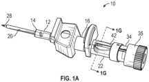
Figure 1A is an upper perspective view of an example catheter system, according to some embodiments; -
Figure 1B is an exploded view of the catheter system ofFigure 1A , according to some embodiments; -
Figure 1C is an upper perspective view of an example flow control plug, according to some embodiments; -
Figure 1D is an upper perspective view of another example flow control plug, according to some embodiments; -
Figure 1E is a cross-sectional view of the catheter system ofFigure 1A , according to some embodiments; -
Figure 1F is an enlarged cross-sectional view of a portion of the catheter system ofFigure 1A , according to some embodiments; -
Figure 1G is a cross-sectional view of the catheter system ofFigure 1A along theline 1G-1G ofFigure 1A , according to some embodiments; -
Figure 2A is an upper perspective view of another example flow control plug, according to some embodiments; -
Figure 2B is a cross-sectional view of the flow control plug ofFigure 2A coupled to the catheter system ofFigure 1A , according to some embodiments; -
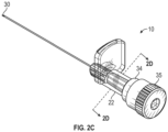
Figure 2C is an upper perspective view if the flow control plug ofFigure 2A coupled to an example needle assembly, according to some embodiments; -
Figure 2D is a transverse cross-sectional view along theline 2D-2D ofFigure 2C , according to some embodiments; -
Figure 3A is an upper perspective view of another example flow control plug, according to some embodiments; -
Figure 3B is a cross-sectional view of the flow control plug ofFigure 3A coupled to the catheter system ofFigure 1A , according to some embodiments; -
Figure 3C is a transverse cross-sectional view of the flow control plug ofFigure 3A coupled to the catheter system ofFigure 1A , according to some embodiments; -
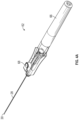
Figure 4A is an upper perspective view of another catheter system, according to some embodiments; -
Figure 4B is a cross-sectional view of the catheter system ofFigure 4A , according to some embodiments; -
Figure 4C is an upper perspective view of an example needle hub of the catheter system ofFigure 4A , according to some embodiments; -
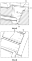
Figure 4D is an enlarged cross-sectional view of an example pocket, according to some embodiments; -
Figure 4E is an enlarged upper perspective view of an example microgroove, according to some embodiments; -
Figure 4F is an upper perspective view of an example inner barrel, according to some embodiments; -
Figure 5A is a cross-sectional view of another example catheter system, according to some embodiments; -
Figure 5B is an upper perspective view of the catheter system ofFigure 5A , illustrating an example outer barrel removed, according to some embodiments; -
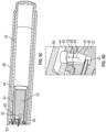
Figure 5C is a cross-sectional view of a proximal end of the catheter system ofFigure 5A , according to some embodiments; -
Figure 5D is an enlarged cross-sectional view of an example pocket of the catheter system ofFigure 5A , according to some embodiments; -
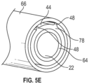
Figure 5E is a transverse cross-sectional view of the catheter system ofFigure 5A , according to some embodiments; -
Figure 6A is a cross-sectional view of an example needle hub being inserted into an example barrel, according to some embodiments; -
Figure 6B is an enlarged cross-sectional view of a portion of the needle hub ofFigure 6A , according to some embodiments; -
Figure 6C is an upper perspective view of the needle hub ofFigure 6A , according to some embodiments; and -
Figure 6D is a lower perspective view of a portion of the needle hub ofFigure 6A , according to some embodiments. - All examples and conditional language recited herein are intended for pedagogical objects to aid the reader in understanding the invention and the concepts contributed by the inventor to furthering the art, and are to be construed as being without limitation to such specifically recited examples and conditions. Although embodiments of the present inventions have been described in detail, it should be understood that the various changes, substitutions, and alterations could be made hereto without departing from the spirit and scope of the invention.
- Referring now to
Figure 1A-1G , in some embodiments, acatheter system 10 may include acatheter adapter 12 which may include adistal end 14, aproximal end 16, and alumen 18 extending through thedistal end 14 and theproximal end 16. In some embodiments, thecatheter system 10 may include acatheter 20 extending distally from thedistal end 14 of thecatheter adapter 12. In some embodiments, thecatheter system 10 may include aneedle hub 22, which may include adistal end 24 and aproximal end 26. In some embodiments, thedistal end 24 of theneedle hub 22 may be coupled to theproximal end 26 of thecatheter adapter 12. - In some embodiments, the
catheter system 10 may include a peripheral intravenous catheter system, such as, for example, the BD NEXIVA™ Closed IV Catheter system, the BD CATHENA™ Catheter system, the BD VENFLON™ Pro Safely Shielded IV Catheter system, the BD NEOFLON™ IV Cannula system, the BD INSYTE™ AUTOGUARD™ BC Shielded IV Catheter system, or another suitable peripheral intravenous catheter system. In some embodiments, thecatheter system 10 may include a PICC system or a midline catheter system. - In some embodiments, the
catheter system 10 may include aneedle 28 which may include adistal end 30 and aproximal end 32. In some embodiments, theneedle 28 may include an introducer needle, which may include a sharp distal tip. In some embodiments, theneedle 28 may be secured within theneedle hub 22. In some embodiments, thecatheter system 10 may include aflow control plug 34, which may be coupled to theproximal end 26 of theneedle hub 22. In some embodiments, the flow control plug 34 may block aproximal opening 36 of theneedle hub 22 such that blood does not exit theproximal opening 36 of theneedle hub 22. In some embodiments, the flow control plug 34 may include one ormore vents 38, which may include a porous membrane or a microgroove that may vent air while containing blood. In some embodiments, acap 35 may be coupled to a proximal end of theflow control plug 34. - In some embodiments, the
catheter system 10 may include aflashback pathway 40 disposed between an outer surface of theflow control plug 34 and an inner surface of theneedle hub 22. In some embodiments, theneedle hub 22 may be constructed of a clear or transparent material, which may facilitate observation blood within theflashback pathway 40. In some embodiments, the needle hub may include alens 42, which may facilitate observation of blood within theflashback pathway 40. In some embodiments, the flow control plug 34 may be constructed of a white material, which may provide a sharp contrast when blood flows into theflashback pathway 40. - In some embodiments, the
lens 42 may be disposed above aproximal end 32 of theneedle 28. In some embodiments, thelens 42 may be integrated within theneedle hub 22. In some embodiments, thelens 42 may be convex or another suitable shape. In some embodiments, an outer surface of thelens 42 may generally conform to a shape of an outer surface of theneedle hub 22. - In some embodiments, the outer surface of the flow control plug 34 may include a
channel 44. In some embodiments, theflashback pathway 40 may extend through thechannel 44 between thechannel 44 and the inner surface of theneedle hub 22. In some embodiments, thechannel 44 may provide a high area-to-volume ratio and may include a small height compared to its width. In some embodiments, a velocity of blood travelling within thechannel 44 may be between 1 mm/s and 2 mm/s. In some embodiments, a velocity of blood travelling within thechannel 44 may between 0.22 mm/s and 2 mm/s, which may create a continuous motion indicative of vein access in a real-time or near real-time manner. In some embodiments, it may take greater than 1 s for blood to move from one end of thechannel 44 to the other. For example, it may take between 5 s and 20 s for blood to move through thechannel 44. In some embodiments, thechannel 44 may be axially aligned with a longitudinal axis of thecatheter system 10. - In some embodiments, the
flashback pathway 40 may provide an unobstructed, sharp-contrast visualization of a small volume of blood. In some embodiments, thecatheter system 10 may provide an effective signal for vein confirmation with a small amount of blood, such as approximately 10 mL. In some embodiments, thechannel 44 may be disposed on a top of theflow control plug 34, as illustrated, for example, inFigure 1A , to ease visibility of theflashback pathway 40. A bevel of the sharp distal tip of theneedle 28 may face toward a top of thecatheter system 10 when thecatheter system 10 is in an insertion position, ready for insertion into a patient, as illustrated, for example, inFigure 1A . - In some embodiments, the outer surface of the flow control plug 34 may include a
pocket 46 proximate thechannel 44. In some embodiments, theproximal end 32 of theneedle 28 may be disposed within thepocket 46. In some embodiments, thepocket 46 may be deeper than thechannel 44. Blood travelling through theflashback pathway 40 may be forced from thepocket 46 to an outside of theflow control plug 34, which may improve visibility of the blood within theflashback pathway 40 to the clinician. - In some embodiments, the
channel 44 may be formed bymultiple side walls 48, which may extend from a bottom of thechannel 44 to the inner surface of theneedle hub 22 and may contact the inner surface of theneedle hub 22. Thus, blood may be contained within thechannel 44 as it travels proximally through thechannel 44. In some embodiments, thevents 38 may be disposed proximate thechannel 44, such as at a proximal end of thechannel 44. In some embodiments, thevents 38 may be disposed at an interface between theproximal end 26 of theneedle hub 22 and theflow control plug 34. - In some embodiments, the
side walls 48 may include elongated ribs. In some embodiments, a height of theside walls 48 from a bottom of thechannel 44 and/or a width of thechannel 44 from one of theside walls 48 to the an opposite of theside walls 48 may increase with an increased gauge size of thecatheter 20. For example, the flow control plug 34 illustrated inFigure 1D may be used with a larger gauge catheter than the flow control plug 34 illustrated inFigure 1C . As another example, the flow control plug 34 illustrated inFigure 3A may be used with a larger gauge catheter than the flow control plug 34 illustrated inFigures 1C and 1D . In some embodiments, the distal end of the flow control plug 34 may include a male luer. In some embodiments, the male luer may include a slip male luer or a threaded male luer. - Referring now to
Figures 2A-2D , in some embodiments, the outer surface of the flow control plug 34 may includemultiple channels 44, and theflashback pathway 40 may extend through thechannels 44 between thechannels 44 and the inner surface of theneedle hub 22. In some embodiments, a number of thechannels 44 may vary. In some embodiments, the outer surface of the flow control plug 34 may include one ormore grooves 50 extending from thechannels 44 inwardly towards a longitudinal axis of theflow control plug 34. In some embodiments, thegrooves 50 may be generally perpendicular to thechannels 44. - In some embodiments, a proximal end of each of the
channels 44 may be formed by aproximal wall 52. In some embodiments, theproximal wall 52 may include one or more microgrooves configured to allow air but not blood to pass. In some embodiments, theproximal wall 52 may interfere with an inner surface of theneedle hub 22, which may prevent blood from exiting the proximal end of thechannel 44. - In some embodiments, the
needle hub 22 may be constructed of a clear or transparent material, which may facilitate observation blood within theflashback pathway 40. In some embodiments, theneedle hub 22 may include one or more lenses, which may facilitate observation of blood within theflashback pathway 40. In some embodiments, the flow control plug 34 may be constructed of a white material, which may provide a sharp contrast when blood flows into theflashback pathway 40. - Referring now to
Figures 3A-3C , in some embodiments, atip 54 of the male luer may include a generallyplanar surface 56, which may extend across thetip 54 such that a shape of theflashback pathway 40 is generally semi-circular. In some embodiments, the flow control plug 34 illustrated inFigure 3A may be used with an 18 or 20 gauge catheter or another suitable size catheter. - Referring now to
Figures 4A-4D , in some embodiments, a catheter assembly 58 of acatheter system 60 may include thecatheter adapter 12 and thecatheter 20. In some embodiments, thecatheter system 60 may include or correspond to thecatheter system 10 of one of more ofFigures 1A-3C . In some embodiments, aneedle assembly 62 of thecatheter system 60 may include one or more of the following: theneedle hub 22, theneedle 28, aninner barrel 64, and anouter barrel 66. In some embodiments, the inner barrel 6 4 may surround theneedle hub 22. In some embodiments, theneedle hub 22 may be secured within theinner barrel 64. In some embodiments, theflashback pathway 40 may be disposed between an outer surface of theneedle hub 22 and an inner surface of theinner barrel 64. In some embodiments, the flow control plug 34 may be constructed of a white material, which may provide a sharp contrast when blood flows into theflashback pathway 40. - In some embodiments, the
outer barrel 66 may surround theinner barrel 64. In some embodiments, theinner barrel 64 and theneedle hub 22 may be configured to move proximally within theouter barrel 66 to retract theneedle 28. In some embodiments, theneedle assembly 62 may include abutton 68 and/or aspring 70. In some embodiments, theinner barrel 64 and theneedle hub 22 may move proximally within theouter barrel 66 in response to depression of thebutton 68 and actuation of thespring 70. In some embodiments, a needle retraction mechanism of thecatheter system 60 may operate similar to the BD INSYTE™ AUTOGUARD™ BC Shielded IV Catheter System or another suitable catheter system. - In some embodiments, the
inner barrel 64 may include a generally hour-glass shape so that its medial portion has a smaller diameter than either end. This shape facilitates engagement between anopening 71 in thebutton 68 and theinner barrel 64. In some embodiments, when thebutton 68 or activation latch is not depressed or is "up" in a non-activated position, aprojection 73 may be located inside thecatheter adapter 12. Thus, when thecatheter 20 is still located on theneedle 28 with thecatheter adapter 12, theprojection 73 may prevent thebutton 68 from being moved "down" into the activated position. - When the
catheter 20 is moved off theneedle 28 so thecatheter adapter 12 is not adjacent to theprojection 73, thebutton 68 may be moved "down," i.e. activated, because thecatheter adapter 12 no longer interferes with the movement of theprojection 73. In this position, theopening 71 is larger than a maximum diameter ofinner barrel 64. Thespring 70 can thus force theneedle hub 22 and theinner barrel 64 to a proximal end of theouter barrel 66 and withdraw the thedistal end 30 of theneedle 28 into theouter barrel 66. In some embodiments, theinner barrel 64 and theneedle hub 22 may be integrally formed or monolithically formed as a single unit. - In some embodiments, the
needle hub 22 may include achannel 44, and theflashback pathway 40 may extend through thechannel 44 between thechannel 44 and the inner surface of theinner barrel 64. In some embodiments, theneedle hub 22 may include apocket 46 proximate thechannel 44. In some embodiments, the proximal end of theneedle 28 may be disposed within thepocket 46. In some embodiments, thepocket 46 may be deeper than thechannel 44. In some embodiments, a proximal end of thechannel 44 may be formed by aproximal wall 52 of theneedle hub 22. In some embodiments, theproximal wall 52 may include one or more vents, which may include a microgroove configured to allow air but not blood to pass. In some embodiments, theproximal wall 52 may interfere with an inner surface of theinner barrel 64. In some embodiments, the inner surface of theinner barrel 64 may include one ormore alignment ridges 74. In some embodiments, the outer surface of theneedle hub 22 may include one or moreother alignment ridges 76, which may contact thealignment ridges 74 to facilitate orientation of theneedle hub 22 with respect to theinner barrel 64. - Referring now to
Figures 5A-5E , in some embodiments, theneedle assembly 62 may include amiddle barrel 78. In some embodiments, theinner barrel 64 may include afirst hole 80 and/or themiddle barrel 78 may include asecond hole 82 aligned with thefirst hole 80 of theinner barrel 64. In some embodiments, theflashback pathway 40 may include thefirst hole 80 and thesecond hole 82 and may extend between an outer surface of themiddle barrel 78 and an inner surface of theouter barrel 66. - In some embodiments, a
pocket 46 may be proximate thefirst hole 80. In some embodiments, theinner barrel 64 and theneedle hub 22 may be configured to move proximally within themiddle barrel 78 to retract theneedle 28. In some embodiments, theinner barrel 64 and theneedle hub 22 may move proximally in response to depression of thebutton 68 and actuation of thespring 70. - In some embodiments, the outer surface of the
middle barrel 78 may include achannel 44, and theflashback pathway 40 may extend through thechannel 44 between thechannel 44 and the inner surface of theinner barrel 64. In some embodiments, theneedle hub 22 may include apocket 46 proximate thechannel 44. In some embodiments, theproximal end 32 of theneedle 28 may be disposed within thepocket 46. In some embodiments, a proximal end of thechannel 44 may be formed by aproximal wall 52 of themiddle barrel 78. In some embodiments, theproximal wall 52 may include one or more vents, which may each include a microgroove configured to allow air but not blood to pass. In some embodiments, theproximal wall 52 may interfere with an inner surface of theouter barrel 66. - In some embodiments, the
channel 44 may be formed bymultiple side walls 48, which may extend from a bottom of thechannel 44 to the inner surface of theouter barrel 66 and may contact the inner surface of theouter barrel 66. Thus, blood may be contained within thechannel 44 as it travels proximally through thechannel 44. - Referring now to
Figures 6A-6B , theneedle hub 22 is illustrated being inserted into theinner barrel 64 during assembly of a catheter system. The catheter system may include or correspond to thecatheter system 60 ofFigures 4A-4F and/orFigures 5A-5E . In some embodiments, theproximal end 26 of theneedle 28 may contact and be secured within theneedle hub 22, but a remaining portion of theneedle 28 may not contact theneedle hub 22 and/or any portion of the catheter system. In some embodiments, theproximal end 26 of theneedle 28 may be pinched and/or glued within theneedle hub 22, as illustrated, for example, inFigure 6B . - Referring now to
Figures 6C-6D , in some embodiments, thevents 38 may be disposed on a bottom of theneedle hub 22, which may facilitate better fluid containment. In some embodiments, flashback may flow proximally through thechannel 44 and then down one or more sides of theneedle hub 22 to a location proximate thevents 38. In some embodiments, a proximal end of theneedle hub 22 may include aseal 84, which may include a rib and/or may extend from one side of thevents 38 to the other. - All examples and conditional language recited herein are intended for pedagogical objects to aid the reader in understanding the invention and the concepts contributed by the inventor to furthering the art, and are to be construed as being without limitation to such specifically recited examples and conditions. Although embodiments of the present inventions have been described in detail, it should be understood that the various changes, substitutions, and alterations could be made hereto without departing from the spirit and scope of the invention.
Further Aspects of the invention are: - 1. A catheter system, comprising:
- a catheter adapter, comprising a distal end, a proximal end, and a lumen extending through the distal end and the proximal end;
- a catheter extending distally from the distal end of the catheter adapter;
- a needle hub, comprising a distal end and a proximal end, wherein the distal end of the needle hub is coupled to the proximal end of the catheter adapter, wherein the needle hub is transparent;
- a needle, comprising a distal end and a proximal end, wherein the needle is secured within the needle hub;
- a flow control plug coupled to the proximal end of the needle hub; and
- a flashback pathway disposed between an outer surface of the flow control plug and an inner surface of the needle hub.
- 2. The catheter system of 1, wherein the outer surface of the flow control plug comprises a channel, wherein the flashback pathway extends through the channel between the channel and the inner surface of the needle hub.
- 3. The catheter system of 2, wherein the outer surface of the flow control plug further comprises a pocket proximate the channel, wherein the proximal end of the needle is disposed within the pocket, wherein the pocket is deeper than the channel.
- 4. The catheter system of 2, wherein the channel is formed by a plurality of side walls that extend from a bottom of the channel to the inner surface of the needle hub and contact the inner surface of the needle hub.
- 5. The catheter system of 2, further comprising a vent disposed proximate the channel and at an interface between the proximal end of the needle hub and the flow control plug.
- 6. The catheter system of 2, wherein the outer surface of the flow control plug comprises a plurality of other channels, further comprising a plurality of other flashback pathways extending through the plurality of other channels between the plurality of other channels and the inner surface of the needle hub.
- 7. The catheter system of 6, wherein the outer surface of the flow control plug further comprises a plurality of grooves extending from the plurality of channels inwardly towards a longitudinal axis of the flow control plug.
- 8. The catheter system of 6, wherein a proximal end of the channel is formed by a proximal wall, wherein the proximal wall comprises a vent configured to allow air but not blood to pass, wherein the proximal wall interferes with an inner surface of the needle hub.
- 9. The catheter system of 1, wherein the distal end of the flow control plug comprises a male luer, wherein the male luer is a slip male luer or a threaded male luer.
- 10. The catheter system of 9, wherein a tip of the male luer comprises a generally planar surface that extends across the tip such that a shape of the flashback pathway is generally semi-circular.
- 11. A catheter system, comprising:
- a catheter assembly, comprising:
- a catheter adapter, comprising a distal end, a proximal end, and a lumen extending through the distal end and the proximal end; and
- a catheter extending distally from the distal end of the catheter adapter; and
- a needle assembly coupled to the catheter assembly, the needle assembly comprising:
- a needle hub;
- a needle, comprising a distal end and a proximal end, wherein the needle is secured within the needle hub;
- an inner barrel surrounding the needle hub, wherein the needle hub is secured within the inner barrel;
- a flashback pathway disposed between an outer surface of the needle hub and an inner surface of the inner barrel; and
- an outer barrel surrounding the inner barrel.
- a catheter assembly, comprising:
- 12. The catheter system of 11, wherein the needle hub comprises a channel, wherein the flashback pathway extends through the channel between the channel and the inner surface of the inner barrel.
- 13. The catheter system of 12, wherein the needle hub further comprises a pocket proximate the channel, wherein the proximal end of the needle is disposed within the pocket, wherein the pocket is deeper than the channel.
- 14. The catheter system of 12, wherein a proximal end of the channel is formed by a proximal wall, wherein the proximal wall comprises a vent configured to allow air but not blood to pass, wherein the proximal wall interferes with an inner surface of the inner barrel.
- 15. The catheter system of 12, wherein an inner surface of the inner barrel includes a plurality of alignment ridges, wherein an outer surface of the needle hub comprises a plurality of other alignment ridges configured to contact the plurality of alignment ridges.
- 16. A catheter system, comprising:
- a catheter assembly, comprising:
- a catheter adapter, comprising a distal end, a proximal end, and a lumen extending through the distal end and the proximal end; and
- a catheter extending distally from the distal end of the catheter adapter; and
- a needle assembly, comprising:
- a needle hub;
- a needle, comprising a distal end and a proximal end, wherein the needle is secured within the needle hub;
- an inner barrel surrounding the needle hub, wherein the needle hub is secured within the inner barrel, wherein the inner barrel comprises a first hole;
- a middle barrel surrounding the inner barrel, wherein the middle barrel comprises a second hole aligned with the first hole;
- an outer barrel surrounding the middle barrel; and
- a flashback pathway comprising the first hole and the second hole and extending between an outer surface of the middle barrel and an inner surface of the outer barrel.
- a catheter assembly, comprising:
- 17. The catheter system of 16, wherein the needle hub further comprises a pocket, wherein the proximal end of the needle is disposed within the pocket, wherein the pocket is proximate the first hole.
- 18. The catheter system of 16, wherein the middle barrel comprises a channel, wherein the channel is formed by a plurality of side walls that extend from a bottom of the channel to the inner surface of the outer barrel and contact the inner surface of the outer barrel.
- 19. The catheter system of 16, wherein the inner barrel and the needle hub are configured to move proximally within the middle barrel to retract the needle.
- 20. The catheter system of 19, wherein the needle assembly comprises a button and a spring, wherein the inner barrel and the needle hub move proximally in response to depression of the button and actuation of the spring.
- 1. A catheter system, comprising:
a catheter assembly, comprising:- a catheter adapter, comprising a distal end, a proximal end, and a lumen extending through the distal end and the proximal end; and
- a catheter extending distally from the distal end of the catheter adapter; and
- a needle assembly, comprising:
- a needle hub;
- a needle, comprising a distal end and a proximal end, wherein the needle is secured within the needle hub;
- an inner barrel surrounding the needle hub, wherein the needle hub is secured within the inner barrel, wherein the inner barrel comprises a first hole;
a middle barrel surrounding the inner barrel, wherein the middle barrel comprises a second hole aligned with the first hole; - an outer barrel surrounding the middle barrel; and
- a flashback pathway comprising the first hole and the second hole and extending between an outer surface of the middle barrel and an inner surface of the outer barrel.
- 2. The catheter system of 1, wherein the needle hub further comprises a pocket, wherein the proximal end of the needle is disposed within the pocket, wherein the pocket is proximate the first hole.
- 3. The catheter system of 1, wherein the middle barrel comprises a channel, wherein the channel is formed by a plurality of side walls that extend from a bottom of the channel to the inner surface of the outer barrel and contact the inner surface of the outer barrel.
- 4. The catheter system of 1, wherein the inner barrel and the needle hub are configured to move proximally within the middle barrel to retract the needle.
- 5. The catheter system of 4, wherein the needle assembly comprises a button and a spring, wherein the inner barrel and the needle hub move proximally in response to depression of the button and actuation of the spring.
Claims (5)
- A catheter system, comprising:a catheter assembly, comprising:a catheter adapter, comprising a distal end, a proximal end, and a lumen extending through the distal end and the proximal end; anda catheter extending distally from the distal end of the catheter adapter; anda needle assembly coupled to the catheter assembly, the needle assembly comprising:a needle hub;a needle, comprising a distal end and a proximal end, wherein the needle is secured within the needle hub;an inner barrel surrounding the needle hub, wherein the needle hub is secured within the inner barrel;a flashback pathway disposed between an outer surface of the needle hub and an inner surface of the inner barrel; andan outer barrel surrounding the inner barrel.
- The catheter system of claim 1, wherein the needle hub comprises a channel, wherein the flashback pathway extends through the channel between the channel and the inner surface of the inner barrel.
- The catheter system of claim 2, wherein the needle hub further comprises a pocket proximate the channel, wherein the proximal end of the needle is disposed within the pocket, wherein the pocket is deeper than the channel.
- The catheter system of claim 2, wherein a proximal end of the channel is formed by a proximal wall, wherein the proximal wall comprises a vent configured to allow air but not blood to pass, wherein the proximal wall interferes with an inner surface of the inner barrel.
- The catheter system of claim 2, wherein an inner surface of the inner barrel includes a plurality of alignment ridges, wherein an outer surface of the needle hub comprises a plurality of other alignment ridges configured to contact the plurality of alignment ridges.
Applications Claiming Priority (5)
| Application Number | Priority Date | Filing Date | Title |
|---|---|---|---|
| US201962901631P | 2019-09-17 | 2019-09-17 | |
| US16/998,592 US11559666B2 (en) | 2019-09-17 | 2020-08-20 | Blood collection devices, systems, and methods facilitating blood flashback |
| PCT/US2020/048003 WO2021055147A1 (en) | 2019-09-17 | 2020-08-26 | Blood collection devices, systems, and methods facilitating blood flashback |
| EP23208249.5A EP4295889B1 (en) | 2019-09-17 | 2020-08-26 | Blood collection devices, systems, and methods facilitating blood flashback |
| EP20768219.6A EP4031226B1 (en) | 2019-09-17 | 2020-08-26 | Blood collection devices, systems, and methods facilitating blood flashback |
Related Parent Applications (3)
| Application Number | Title | Priority Date | Filing Date |
|---|---|---|---|
| EP23208249.5A Division EP4295889B1 (en) | 2019-09-17 | 2020-08-26 | Blood collection devices, systems, and methods facilitating blood flashback |
| EP23208249.5A Division-Into EP4295889B1 (en) | 2019-09-17 | 2020-08-26 | Blood collection devices, systems, and methods facilitating blood flashback |
| EP20768219.6A Division EP4031226B1 (en) | 2019-09-17 | 2020-08-26 | Blood collection devices, systems, and methods facilitating blood flashback |
Publications (2)
| Publication Number | Publication Date |
|---|---|
| EP4570295A2 true EP4570295A2 (en) | 2025-06-18 |
| EP4570295A3 EP4570295A3 (en) | 2025-09-24 |
Family
ID=74868875
Family Applications (3)
| Application Number | Title | Priority Date | Filing Date |
|---|---|---|---|
| EP25174238.3A Pending EP4570295A3 (en) | 2019-09-17 | 2020-08-26 | Blood collection devices, systems, and methods facilitating blood flashback |
| EP20768219.6A Active EP4031226B1 (en) | 2019-09-17 | 2020-08-26 | Blood collection devices, systems, and methods facilitating blood flashback |
| EP23208249.5A Active EP4295889B1 (en) | 2019-09-17 | 2020-08-26 | Blood collection devices, systems, and methods facilitating blood flashback |
Family Applications After (2)
| Application Number | Title | Priority Date | Filing Date |
|---|---|---|---|
| EP20768219.6A Active EP4031226B1 (en) | 2019-09-17 | 2020-08-26 | Blood collection devices, systems, and methods facilitating blood flashback |
| EP23208249.5A Active EP4295889B1 (en) | 2019-09-17 | 2020-08-26 | Blood collection devices, systems, and methods facilitating blood flashback |
Country Status (12)
| Country | Link |
|---|---|
| US (3) | US11559666B2 (en) |
| EP (3) | EP4570295A3 (en) |
| JP (1) | JP2022549161A (en) |
| KR (1) | KR102936173B1 (en) |
| CN (2) | CN114502228A (en) |
| AU (1) | AU2020348201B2 (en) |
| BR (1) | BR112022004287A2 (en) |
| CA (1) | CA3149985A1 (en) |
| ES (1) | ES2969599T3 (en) |
| MX (1) | MX2022002386A (en) |
| MY (1) | MY207518A (en) |
| WO (1) | WO2021055147A1 (en) |
Families Citing this family (2)
| Publication number | Priority date | Publication date | Assignee | Title |
|---|---|---|---|---|
| US12350453B2 (en) * | 2020-06-10 | 2025-07-08 | Becton, Dickinson And Company | Catheter system facilitating blood flashback visualization |
| US20250032758A1 (en) | 2021-12-08 | 2025-01-30 | Smiths Medical Asd, Inc. | Needle assemblies and safety catheter assemblies with blood diverting feature |
Family Cites Families (21)
| Publication number | Priority date | Publication date | Assignee | Title |
|---|---|---|---|---|
| US4193400A (en) | 1978-06-16 | 1980-03-18 | The Deseret Company | Intravenous needle assembly with air bleed plug |
| US5032116A (en) * | 1991-01-09 | 1991-07-16 | Becton, Dickinson And Company | Flashback plug |
| US5246426A (en) * | 1992-06-17 | 1993-09-21 | Arrow International Investment Corp. | Catheterization system |
| DE9405166U1 (en) * | 1994-03-26 | 1994-05-26 | Krebs, Peter, Dr., 78048 Villingen-Schwenningen | Spinal cannula with transparent handle |
| US5800399A (en) * | 1996-08-27 | 1998-09-01 | Johnson & Johnson Medical, Inc. | Low-cost method of assembling an extruded cannula holder for a catheter insertion device |
| US7179244B2 (en) * | 2001-03-15 | 2007-02-20 | Specialized Health Products, Inc. | Resettable safety shield for medical needles |
| KR20040023689A (en) * | 2001-07-27 | 2004-03-18 | 벡톤 디킨슨 앤드 컴퍼니 | Luer connector assembly |
| JP4925716B2 (en) * | 2006-04-28 | 2012-05-09 | メディキット株式会社 | Indwelling needle assembly |
| EP3093038B1 (en) * | 2007-04-18 | 2019-05-22 | Access Scientific, Inc. | Access device |
| US7766879B2 (en) | 2008-03-07 | 2010-08-03 | Becton, Dickinson And Company | Flashback blood collection needle |
| US8603009B2 (en) * | 2008-03-07 | 2013-12-10 | Becton, Dickinson And Company | Flashback blood collection needle |
| US8597252B2 (en) * | 2010-07-15 | 2013-12-03 | Becton, Dickinson And Company | Removable flash chamber |
| JP6059497B2 (en) * | 2012-10-03 | 2017-01-11 | メディキット株式会社 | Needle assembly |
| US20140257359A1 (en) * | 2013-03-11 | 2014-09-11 | St. Jude Medical Puerto Rico Llc | Temporary sealing device with blood flashback for vessel location |
| US9566087B2 (en) * | 2013-03-15 | 2017-02-14 | Access Scientific, Llc | Vascular access device |
| US10744305B2 (en) | 2015-10-28 | 2020-08-18 | Becton, Dickinson And Company | Ergonomic IV systems and methods |
| US10549072B2 (en) * | 2015-10-28 | 2020-02-04 | Becton, Dickinson And Company | Integrated catheter with independent fluid paths |
| US10639455B2 (en) * | 2015-10-28 | 2020-05-05 | Becton, Dickinson And Company | Closed IV access device with paddle grip needle hub and flash chamber |
| US10850046B2 (en) * | 2016-03-28 | 2020-12-01 | Becton, Dickinson And Company | Cannula locator device |
| US11278705B2 (en) * | 2017-05-04 | 2022-03-22 | Becton, Dickinson And Company | Intravenous catheter systems and methods |
| US11077260B2 (en) * | 2018-02-14 | 2021-08-03 | Becton, Dickinson And Company | Flow control plug securement |
-
2020
- 2020-08-20 US US16/998,592 patent/US11559666B2/en active Active
- 2020-08-26 CN CN202080066173.7A patent/CN114502228A/en active Pending
- 2020-08-26 MX MX2022002386A patent/MX2022002386A/en unknown
- 2020-08-26 WO PCT/US2020/048003 patent/WO2021055147A1/en not_active Ceased
- 2020-08-26 JP JP2022517420A patent/JP2022549161A/en active Pending
- 2020-08-26 EP EP25174238.3A patent/EP4570295A3/en active Pending
- 2020-08-26 KR KR1020227010381A patent/KR102936173B1/en active Active
- 2020-08-26 CA CA3149985A patent/CA3149985A1/en active Pending
- 2020-08-26 MY MYPI2022001110A patent/MY207518A/en unknown
- 2020-08-26 ES ES20768219T patent/ES2969599T3/en active Active
- 2020-08-26 EP EP20768219.6A patent/EP4031226B1/en active Active
- 2020-08-26 EP EP23208249.5A patent/EP4295889B1/en active Active
- 2020-08-26 CN CN202410804901.XA patent/CN118743812A/en active Pending
- 2020-08-26 AU AU2020348201A patent/AU2020348201B2/en active Active
- 2020-08-26 BR BR112022004287A patent/BR112022004287A2/en unknown
-
2023
- 2023-01-03 US US18/092,798 patent/US12233225B2/en active Active
-
2025
- 2025-01-31 US US19/042,720 patent/US20250177703A1/en active Pending
Also Published As
| Publication number | Publication date |
|---|---|
| CA3149985A1 (en) | 2021-03-25 |
| MY207518A (en) | 2025-03-01 |
| KR20220064979A (en) | 2022-05-19 |
| EP4295889C0 (en) | 2025-07-02 |
| WO2021055147A1 (en) | 2021-03-25 |
| US20210077786A1 (en) | 2021-03-18 |
| EP4570295A3 (en) | 2025-09-24 |
| NZ786159A (en) | 2025-09-26 |
| US12233225B2 (en) | 2025-02-25 |
| EP4031226A1 (en) | 2022-07-27 |
| CN114502228A (en) | 2022-05-13 |
| US20250177703A1 (en) | 2025-06-05 |
| AU2020348201A1 (en) | 2022-04-07 |
| AU2020348201B2 (en) | 2025-09-11 |
| US20230141587A1 (en) | 2023-05-11 |
| US11559666B2 (en) | 2023-01-24 |
| JP2022549161A (en) | 2022-11-24 |
| EP4295889A3 (en) | 2024-04-10 |
| BR112022004287A2 (en) | 2022-06-21 |
| EP4295889A2 (en) | 2023-12-27 |
| EP4031226B1 (en) | 2024-01-03 |
| EP4031226C0 (en) | 2024-01-03 |
| EP4295889B1 (en) | 2025-07-02 |
| MX2022002386A (en) | 2022-03-17 |
| CN118743812A (en) | 2024-10-08 |
| KR102936173B1 (en) | 2026-03-09 |
| ES2969599T3 (en) | 2024-05-21 |
Similar Documents
| Publication | Publication Date | Title |
|---|---|---|
| US20250177703A1 (en) | Blood collection devices, systems, and methods facilitating blood flashback | |
| US11931148B2 (en) | Catheter system to facilitate blood sampling and related methods | |
| CA3148871A1 (en) | Catheter system to facilitate blood collection and related methods | |
| EP4058122B1 (en) | Catheter systems for flashback visualization at various blood pressures | |
| EP4161624B1 (en) | Needle cover retention | |
| CN215900667U (en) | Catheter system | |
| EP4674463A2 (en) | Catheter vent assembly and related systems and methods | |
| CA3156545C (en) | Catheter systems and methods for flashback visualization at various blood pressures | |
| CA3148875C (en) | Catheter system to facilitate blood sampling and related methods | |
| BR112022008723B1 (en) | CATHETER SYSTEMS | |
| CA3109405A1 (en) | Catheter stabilization platform, systems, and methods |
Legal Events
| Date | Code | Title | Description |
|---|---|---|---|
| PUAI | Public reference made under article 153(3) epc to a published international application that has entered the european phase |
Free format text: ORIGINAL CODE: 0009012 |
|
| STAA | Information on the status of an ep patent application or granted ep patent |
Free format text: STATUS: THE APPLICATION HAS BEEN PUBLISHED |
|
| AC | Divisional application: reference to earlier application |
Ref document number: 4031226 Country of ref document: EP Kind code of ref document: P Ref document number: 4295889 Country of ref document: EP Kind code of ref document: P |
|
| AK | Designated contracting states |
Kind code of ref document: A2 Designated state(s): AL AT BE BG CH CY CZ DE DK EE ES FI FR GB GR HR HU IE IS IT LI LT LU LV MC MK MT NL NO PL PT RO RS SE SI SK SM TR |
|
| PUAL | Search report despatched |
Free format text: ORIGINAL CODE: 0009013 |
|
| AK | Designated contracting states |
Kind code of ref document: A3 Designated state(s): AL AT BE BG CH CY CZ DE DK EE ES FI FR GB GR HR HU IE IS IT LI LT LU LV MC MK MT NL NO PL PT RO RS SE SI SK SM TR |
|
| RIC1 | Information provided on ipc code assigned before grant |
Ipc: A61M 25/06 20060101AFI20250821BHEP |
|
| STAA | Information on the status of an ep patent application or granted ep patent |
Free format text: STATUS: REQUEST FOR EXAMINATION WAS MADE |
|
| 17P | Request for examination filed |
Effective date: 20260318 |