EP4570228A1 - Head-up cardiopulmonary resuscitation device based on cerebral blood flow measurement, and method for operating same - Google Patents
Head-up cardiopulmonary resuscitation device based on cerebral blood flow measurement, and method for operating same Download PDFInfo
- Publication number
- EP4570228A1 EP4570228A1 EP23852945.7A EP23852945A EP4570228A1 EP 4570228 A1 EP4570228 A1 EP 4570228A1 EP 23852945 A EP23852945 A EP 23852945A EP 4570228 A1 EP4570228 A1 EP 4570228A1
- Authority
- EP
- European Patent Office
- Prior art keywords
- angle
- patient
- blood flow
- cerebral blood
- head
- Prior art date
- Legal status (The legal status is an assumption and is not a legal conclusion. Google has not performed a legal analysis and makes no representation as to the accuracy of the status listed.)
- Pending
Links
Images




Classifications
-
- A—HUMAN NECESSITIES
- A61—MEDICAL OR VETERINARY SCIENCE; HYGIENE
- A61H—PHYSICAL THERAPY APPARATUS, e.g. DEVICES FOR LOCATING OR STIMULATING REFLEX POINTS IN THE BODY; ARTIFICIAL RESPIRATION; MASSAGE; BATHING DEVICES FOR SPECIAL THERAPEUTIC OR HYGIENIC PURPOSES OR SPECIFIC PARTS OF THE BODY
- A61H31/00—Artificial respiration by a force applied to the chest; Heart stimulation, e.g. heart massage
-
- A—HUMAN NECESSITIES
- A61—MEDICAL OR VETERINARY SCIENCE; HYGIENE
- A61B—DIAGNOSIS; SURGERY; IDENTIFICATION
- A61B5/00—Measuring for diagnostic purposes; Identification of persons
- A61B5/68—Arrangements of detecting, measuring or recording means, e.g. sensors, in relation to patient
- A61B5/6801—Arrangements of detecting, measuring or recording means, e.g. sensors, in relation to patient specially adapted to be attached to or worn on the body surface
- A61B5/6813—Specially adapted to be attached to a specific body part
- A61B5/6814—Head
-
- A—HUMAN NECESSITIES
- A61—MEDICAL OR VETERINARY SCIENCE; HYGIENE
- A61B—DIAGNOSIS; SURGERY; IDENTIFICATION
- A61B5/00—Measuring for diagnostic purposes; Identification of persons
-
- A—HUMAN NECESSITIES
- A61—MEDICAL OR VETERINARY SCIENCE; HYGIENE
- A61B—DIAGNOSIS; SURGERY; IDENTIFICATION
- A61B5/00—Measuring for diagnostic purposes; Identification of persons
- A61B5/48—Other medical applications
- A61B5/4836—Diagnosis combined with treatment in closed-loop systems or methods
-
- A—HUMAN NECESSITIES
- A61—MEDICAL OR VETERINARY SCIENCE; HYGIENE
- A61H—PHYSICAL THERAPY APPARATUS, e.g. DEVICES FOR LOCATING OR STIMULATING REFLEX POINTS IN THE BODY; ARTIFICIAL RESPIRATION; MASSAGE; BATHING DEVICES FOR SPECIAL THERAPEUTIC OR HYGIENIC PURPOSES OR SPECIFIC PARTS OF THE BODY
- A61H31/00—Artificial respiration by a force applied to the chest; Heart stimulation, e.g. heart massage
- A61H31/008—Supine patient supports or bases, e.g. improving air-way access to the lungs
-
- A—HUMAN NECESSITIES
- A61—MEDICAL OR VETERINARY SCIENCE; HYGIENE
- A61H—PHYSICAL THERAPY APPARATUS, e.g. DEVICES FOR LOCATING OR STIMULATING REFLEX POINTS IN THE BODY; ARTIFICIAL RESPIRATION; MASSAGE; BATHING DEVICES FOR SPECIAL THERAPEUTIC OR HYGIENIC PURPOSES OR SPECIFIC PARTS OF THE BODY
- A61H37/00—Accessories for massage
-
- A—HUMAN NECESSITIES
- A61—MEDICAL OR VETERINARY SCIENCE; HYGIENE
- A61H—PHYSICAL THERAPY APPARATUS, e.g. DEVICES FOR LOCATING OR STIMULATING REFLEX POINTS IN THE BODY; ARTIFICIAL RESPIRATION; MASSAGE; BATHING DEVICES FOR SPECIAL THERAPEUTIC OR HYGIENIC PURPOSES OR SPECIFIC PARTS OF THE BODY
- A61H1/00—Apparatus for passive exercising; Vibrating apparatus; Chiropractic devices, e.g. body impacting devices, external devices for briefly extending or aligning unbroken bones
- A61H1/02—Stretching or bending or torsioning apparatus for exercising
- A61H1/0292—Stretching or bending or torsioning apparatus for exercising for the spinal column
-
- A—HUMAN NECESSITIES
- A61—MEDICAL OR VETERINARY SCIENCE; HYGIENE
- A61H—PHYSICAL THERAPY APPARATUS, e.g. DEVICES FOR LOCATING OR STIMULATING REFLEX POINTS IN THE BODY; ARTIFICIAL RESPIRATION; MASSAGE; BATHING DEVICES FOR SPECIAL THERAPEUTIC OR HYGIENIC PURPOSES OR SPECIFIC PARTS OF THE BODY
- A61H2201/00—Characteristics of apparatus not provided for in the preceding codes
- A61H2201/01—Constructive details
- A61H2201/0119—Support for the device
-
- A—HUMAN NECESSITIES
- A61—MEDICAL OR VETERINARY SCIENCE; HYGIENE
- A61H—PHYSICAL THERAPY APPARATUS, e.g. DEVICES FOR LOCATING OR STIMULATING REFLEX POINTS IN THE BODY; ARTIFICIAL RESPIRATION; MASSAGE; BATHING DEVICES FOR SPECIAL THERAPEUTIC OR HYGIENIC PURPOSES OR SPECIFIC PARTS OF THE BODY
- A61H2201/00—Characteristics of apparatus not provided for in the preceding codes
- A61H2201/01—Constructive details
- A61H2201/0192—Specific means for adjusting dimensions
- A61H2201/0196—Specific means for adjusting dimensions automatically adjusted according to anthropometric data of the user
-
- A—HUMAN NECESSITIES
- A61—MEDICAL OR VETERINARY SCIENCE; HYGIENE
- A61H—PHYSICAL THERAPY APPARATUS, e.g. DEVICES FOR LOCATING OR STIMULATING REFLEX POINTS IN THE BODY; ARTIFICIAL RESPIRATION; MASSAGE; BATHING DEVICES FOR SPECIAL THERAPEUTIC OR HYGIENIC PURPOSES OR SPECIFIC PARTS OF THE BODY
- A61H2201/00—Characteristics of apparatus not provided for in the preceding codes
- A61H2201/16—Physical interface with patient
- A61H2201/1602—Physical interface with patient kind of interface, e.g. head rest, knee support or lumbar support
- A61H2201/1604—Head
-
- A—HUMAN NECESSITIES
- A61—MEDICAL OR VETERINARY SCIENCE; HYGIENE
- A61H—PHYSICAL THERAPY APPARATUS, e.g. DEVICES FOR LOCATING OR STIMULATING REFLEX POINTS IN THE BODY; ARTIFICIAL RESPIRATION; MASSAGE; BATHING DEVICES FOR SPECIAL THERAPEUTIC OR HYGIENIC PURPOSES OR SPECIFIC PARTS OF THE BODY
- A61H2201/00—Characteristics of apparatus not provided for in the preceding codes
- A61H2201/16—Physical interface with patient
- A61H2201/1602—Physical interface with patient kind of interface, e.g. head rest, knee support or lumbar support
- A61H2201/1604—Head
- A61H2201/1607—Holding means therefor
-
- A—HUMAN NECESSITIES
- A61—MEDICAL OR VETERINARY SCIENCE; HYGIENE
- A61H—PHYSICAL THERAPY APPARATUS, e.g. DEVICES FOR LOCATING OR STIMULATING REFLEX POINTS IN THE BODY; ARTIFICIAL RESPIRATION; MASSAGE; BATHING DEVICES FOR SPECIAL THERAPEUTIC OR HYGIENIC PURPOSES OR SPECIFIC PARTS OF THE BODY
- A61H2201/00—Characteristics of apparatus not provided for in the preceding codes
- A61H2201/50—Control means thereof
-
- A—HUMAN NECESSITIES
- A61—MEDICAL OR VETERINARY SCIENCE; HYGIENE
- A61H—PHYSICAL THERAPY APPARATUS, e.g. DEVICES FOR LOCATING OR STIMULATING REFLEX POINTS IN THE BODY; ARTIFICIAL RESPIRATION; MASSAGE; BATHING DEVICES FOR SPECIAL THERAPEUTIC OR HYGIENIC PURPOSES OR SPECIFIC PARTS OF THE BODY
- A61H2201/00—Characteristics of apparatus not provided for in the preceding codes
- A61H2201/50—Control means thereof
- A61H2201/5058—Sensors or detectors
- A61H2201/5092—Optical sensor
-
- A—HUMAN NECESSITIES
- A61—MEDICAL OR VETERINARY SCIENCE; HYGIENE
- A61H—PHYSICAL THERAPY APPARATUS, e.g. DEVICES FOR LOCATING OR STIMULATING REFLEX POINTS IN THE BODY; ARTIFICIAL RESPIRATION; MASSAGE; BATHING DEVICES FOR SPECIAL THERAPEUTIC OR HYGIENIC PURPOSES OR SPECIFIC PARTS OF THE BODY
- A61H2203/00—Additional characteristics concerning the patient
- A61H2203/04—Position of the patient
- A61H2203/0443—Position of the patient substantially horizontal
- A61H2203/0456—Supine
-
- A—HUMAN NECESSITIES
- A61—MEDICAL OR VETERINARY SCIENCE; HYGIENE
- A61H—PHYSICAL THERAPY APPARATUS, e.g. DEVICES FOR LOCATING OR STIMULATING REFLEX POINTS IN THE BODY; ARTIFICIAL RESPIRATION; MASSAGE; BATHING DEVICES FOR SPECIAL THERAPEUTIC OR HYGIENIC PURPOSES OR SPECIFIC PARTS OF THE BODY
- A61H2230/00—Measuring physical parameters of the user
- A61H2230/25—Blood flowrate, e.g. by Doppler effect
- A61H2230/255—Blood flowrate, e.g. by Doppler effect used as a control parameter for the apparatus
Definitions
- the present disclosure relates to a cardiopulmonary resuscitation device and a method for operating the same. Specifically, the present disclosure relates to a cardiopulmonary resuscitation device capable of allowing a patient to take a head-up posture and performing emergency treatment based on cerebral blood flow measurement of the patient in the head-up posture, and a method for operating the cardiopulmonary resuscitation device.
- Acute cardiac arrest is one of the diseases that poses a large burden on public health due to its increasing incidence every year and low survival rate.
- the survival rate of psychogenic acute cardiac arrest in Korea increased from 2.3% in 2007 to 5.5% in 2017, and the brain function recovery rate thereof increased from 0.6% in 2007 to 3.1% in 2017.
- most patients with acute cardiac arrest still die or develop severe neurological disorders.
- Chest compression in the supine position which is a standard cardiopulmonary resuscitation chest compression position, is commonly performed for cardiopulmonary resuscitation position.
- the chest compression in the supine position for cardiopulmonary resuscitation is performed, the blood volume and the pressure in the arterial system and the right heart are increased and transmitted to the brain through the jugular vein and the paravertebral venous plexus, thereby increasing the intracranial pressure and decreasing the brain perfusion.
- the intracranial pressure is typically high in patients in a supine position, and patients with traumatic brain injury are typically subjected to a head-raising posture in a non-invasive manner to reduce the intracranial pressure.
- cardiopulmonary resuscitation in a head-up posture which is the head-raising posture, increases the venous return from the brain to the heart by gravity, reduces the intracranial pressure, and improves the cardiac preload.
- head-up cardiopulmonary resuscitation reduces perfusion of the intracranial pressure, thereby increasing the cerebral perfusion pressure and the cerebral blood flow.
- a cardiopulmonary resuscitation device that enables a patient with cardiac arrest to take a stable head-up posture and performs precise emergency treatment by measuring the cerebral blood flow of the patient in real time.
- the technical problem to be solved by the present disclosure is to provide a cardiopulmonary resuscitation device that enables a patient to take a stable head-up posture and performs precise emergency treatment by measuring the cerebral blood flow of the patient in real time.
- Another technical problem to be solved by the present disclosure is to provide a method for operating the cardiopulmonary resuscitation device that enables a patient to have a stable head-up posture and performs precise emergency treatment by measuring the cerebral blood flow of the patient in real time.
- a cardiopulmonary resuscitation device for achieving the above technical problem may include: a cardiopulmonary resuscitation board including a head support part, which includes a receiving portion formed concavely in order to support at least a portion of a patient's head, a support, which is disposed at the bottom of the head support part and adjusts the angle of the patient's head, a backboard for supporting the patient's back, and a belt for securing the patient; a cerebral blood flow measurement device for measuring the real-time cerebral blood flow of the patient according to the angle of the patient's head; and a control unit for controlling to adjust the angle between the support and the backboard within a preset angle range on the basis of the measured cerebral blood flow of the patient.
- the preset angle range may be 10 degrees to 45 degrees.
- the control unit may operate in either a first mode or a second mode different from each other, and secure the support when the real-time cerebral blood flow of the patient satisfies a predetermined condition according to the mode of the control unit.
- control unit When the control unit operates in the first mode, the control unit may adjust the support so that the angle between the support and the backboard gradually increases, and secure the support at a specific angle when the real-time cerebral blood flow of the patient at the specific angle has a value greater than a predetermined target cerebral blood flow.
- the predetermined target cerebral blood flow may be 1.15 times the real-time cerebral blood flow of the patient when the angle between the support and the backboard is 0 degree.
- the control unit may adjust the support so that the angle between the support and the backboard corresponds to each of first to N th angles within the preset angle range, and secure the support at an angle at which the greatest increase in cerebral blood flow is exhibited among the first to N th angles, wherein an i th angle (i is a natural number between 2 and N) among the first to N th angles may be greater than an i-1 th angle, the first angle may be a minimum value of the preset angle range, and the N th angle may be a maximum value of the preset angle range.
- the difference between the i th angle and the i-1 th angle may have a constant value.
- the cerebral blood flow measurement device may include an inspection patch attached to an occipital region of the patient to obtain a cerebral blood flow signal.
- the cerebral blood flow measurement device may be a near-infrared spectroscopy (NIRS) device.
- NIRS near-infrared spectroscopy
- a method for operating a cardiopulmonary resuscitation device may include: adjusting an angle between a back of a patient and a head of the patient using a support, according to an operation mode of a control unit; measuring a real-time cerebral blood flow of the patient according to an angle of the head of the patient by using an inspection patch attached to the occipital region of the patient to obtain a cerebral blood flow signal; searching for an angle satisfying a predetermined condition according to an operation mode of the control unit; and securing the support at an angle satisfying the predetermined condition, wherein the searching for the angle satisfying the predetermined condition may be based on determining whether the measured real-time cerebral blood flow of the patient at least at any angle has a value greater than the predetermined cerebral blood flow.
- the angle between the patient's back and the patient's head may be adjusted between 10 degrees and 45 degrees.
- the predetermined target cerebral blood flow may be 1.15 times a real-time cerebral blood flow of the patient when the angle between the patient's back and the patient's head is 0 degree.
- the operation mode of the control unit may include: a first mode for adjusting the support so that the angle between the patient's back and the patient's head gradually increases; and a second mode for adjusting the support so that the angle between the patient's back and the patient's head corresponds to each of first to N th angles within the preset angle range, wherein the i th angle (i is a natural number between 2 and N) among the first to N th angles may be greater than the i-1 th angle, the first angle may be a minimum value of the preset angle range, and the N th angle may be a maximum value of the preset angle range.
- the searching for an angle satisfying the predetermined condition may include searching for an angle at which the greatest increase in cerebral blood flow is exhibited among the first to N th angles.
- the real-time cerebral blood flow of the patient may be measured by the NIRS device.
- a cardiopulmonary resuscitation device and a method for operating the same may stably position a head of a patient higher than a heart of the patient to increase a brain perfusion pressure and a cerebral blood flow, thereby improving a neurological prognosis of the patient, and may measure a cerebral blood flow of the patient in real time according to an angle of the head of the patient, thereby determining a posture of the patient for effective cardiopulmonary resuscitation.
- FIG. 1 is an exemplary block diagram of a cardiopulmonary resuscitation device according to some embodiments.
- a cardiopulmonary resuscitation device 1 may include a cardiopulmonary resuscitation board 10, a cerebral blood flow measurement device 20, and a control unit 30.
- the cardiopulmonary resuscitation board 10 may allow a patient to assume a stable head-up posture during cardiopulmonary resuscitation through the various configurations described with reference to FIG. 2 . Details thereof are described with reference to FIG. 2 .
- the cerebral blood flow measurement device 20 may measure the patient's real-time cerebral blood flow. Specifically, the cerebral blood flow measurement device 20 may measure the real-time cerebral blood flow of the patient according to an angle of the head of the patient.
- the angle of the patient's head may refer to an angle between the patient's back and the patient's neck. Specifically, the angle of the patient's head may refer to an angle between the patient's back and the start of the neck toward the patient's shoulder when the patient's back is in close contact with the backboard of the cardiopulmonary resuscitation board 10.
- the cerebral blood flow measurement device 20 may provide information on the measured real-time cerebral blood flow of the patient to the control unit 30.
- the control unit 30 may control the operation of the cardiopulmonary resuscitation board 10 based on the measured cerebral blood flow of the patient. Specifically, the control unit 30 may control the cardiopulmonary resuscitation board 10 to adjust the angle of the patient's head within a preset angle range.
- the preset angle range may be 10 degrees to 45 degrees, but the embodiment is not limited thereto.
- the preset angle range may be variously changed according to the embodiment.
- control unit 30 may receive information on the measured real-time cerebral blood flow of the patient from the cerebral blood flow measurement device 20, and control the cardiopulmonary resuscitation board 10 to fix the angle of the patient's head to a specific angle when the real-time cerebral flow satisfies a predetermined condition according to an operation mode.
- control unit 30 may operate in either a first mode or a second mode.
- the control unit 30 may control the cardiopulmonary resuscitation board 10 so that the angle of the patient's head gradually increases.
- the control unit 30 may control the cardiopulmonary resuscitation board 10 to be fixed at the corresponding specific angle.
- the target cerebral blood flow may be 1.15 times greater than the real-time cerebral blood flow of the patient, for example, when the angle between the patient's back and the patient's head is 0 degree.
- the embodiments are not limited thereto.
- the target cerebral blood flow may be variously changed according to the embodiments.
- the control unit 30 may control the cardiopulmonary resuscitation board 10 so that the angle of the head of the patient corresponds to each of the first to N th angles within the above-described preset angle range. While the control unit 30 operates in the second mode so that the angle of the patient's head corresponds to each of the first through N th angles, the cerebral blood flow of the patient at each angle may be measured by the cerebral blood flow measurement device 20 at each angle. At this time, the control unit 30 may control the cardiopulmonary resuscitation board 10 to be fixed at the angle at which the greatest increase in cerebral blood flow is exhibited among the first to N th angles.
- an i th angle (i is a natural number between 2 and N) among the first to N th angles may be greater than the i-1 th angle
- the first angle may be a minimum value of the preset angle range
- the N th angle may be a maximum value of the preset angular range. That is, when the preset angle range is 10 degrees to 45 degrees as described above, the first angle may refer to 10 degrees, and the N th angle may refer to 45 degrees.
- a difference between the i th angle and the i-1 th angle may have a constant value.
- the control unit 30 may control the cardiopulmonary resuscitation board 10 so that the angle of the head of the patient corresponds to each of 10 degrees, 15 degrees, 20 degrees, 25 degrees, 30 degrees, 35 degrees, 40 degrees, and 45 degrees.
- the first to N th angles may be variously changed according to the present angle range and the difference between the i th angle and the i-1 th angle.
- the control unit 30 may control the cardiopulmonary resuscitation board 10 so that the angle of the head of the patient corresponds to each of 15 degrees, 25 degrees, and 35 degrees.
- FIG. 1 shows that the control unit 30 is separate from the cardiopulmonary resuscitation board 10 and the cerebral blood flow measurement device 20, the embodiment is not limited thereto.
- the control unit 30 may be integrally formed by being mounted inside the cardiopulmonary resuscitation board 10 or may be integrally formed by being mounted inside the cerebral blood flow measurement device 20.
- FIG. 2 is an exemplary diagram of a cardiopulmonary resuscitation board according to some embodiments.
- the cardiopulmonary resuscitation board 10 may include a head support part 11, a support 12, a backboard 13, a shoulder securing belt 14, and a forehead securing belt 15.
- the head support part 11 may be configured to support at least a part of the head of a patient P.
- the head support part 11 may be made of a fluffy material to minimize damage to the scalp even if the patient lies down for a long time of 30 minutes or more.
- the head support part 11 may include a receiving portion that is manufactured to be suitable for the head of a human body so that the occipital region can be suitably received in the head support part 11. Details thereof are described with reference to FIG. 3 .
- the support 12 may be disposed below the head support part 11 to adjust the angle of the head of the patient P.
- the backboard 13 may support the back of the patient P.
- the backboard 13 may be configured to provide a firm repulsive force to the lower back of the patient during cardiopulmonary resuscitation.
- the shoulder securing belt 14 may secure the shoulder of the patient P.
- the forehead securing belt 15 may secure the head of the patient P.
- the support 12 may adjust the angle of the head of the patient P under the control of the control unit 30 of FIG. 1 . Specifically, to increase the angle of the head of the patient P, the support 12 may increase the inclination of its surface in contact with the head support part 11 under the control of the control unit 30. To decrease the angle of the head of the patient P, the support 12 may decrease the inclination of its surface in contact with the head support part 11 under the control of the control unit 30.
- the angle of the head of the patient P may refer to an angle between the backboard 13 and the surface of the support 12 in contact with the head support part 11. That is, the angle between the backboard 13 and the surface of the support 12 in contact with the head support part 11 may correspond to the angle between the back of the patient P and the neck of the patient P described with reference to FIG. 1 .
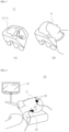
- FIG. 3 is an exemplary diagram of a receiving portion according to some embodiments.
- the head support part 11 may include a receiving portion 11_1.
- the head support part 11 may include the receiving portion 11_1 formed to be concave to support at least a part of the head of the patient P.
- FIG. 3 (B) it is possible to provide an environment in which the patient P may take a stable posture through the receiving portion 11_1.
- the shape of the receiving portion 11_1 is not necessarily limited to the shape shown in FIG. 3 .
- the shape of the receiving portion 11_1 may be changed to various shapes capable of stably and appropriately supporting at least a part of the patient's head.
- FIG. 4 is an exemplary diagram of a cerebral blood flow measurement device according to some embodiments.
- the cerebral blood flow measurement device 20 may include a cerebral blood flow analysis device 21 and an inspection patch 22.
- the cerebral blood flow analysis device 21 may analyze a cerebral blood flow signal received from the inspection patch 22 to analyze the real-time cerebral blood flow of the patient P.
- the cerebral blood flow analysis device 21 may analyze the cerebral blood flow using near-infrared spectroscopy (NIRS).
- NIRS near-infrared spectroscopy
- the cerebral blood flow analysis device 21 may measure the cerebral blood flow of the patient P through any other appropriate methods according to the embodiment.
- the cerebral blood flow analysis device 21 may use a micro light emitted diode (LED) to obtain an improved cerebral blood flow signal of the patient P, but the embodiment is not necessarily limited thereto.
- LED micro light emitted diode
- the inspection patch 22 may be attached to the skin of the patient P to obtain the cerebral blood flow signal.
- the inspection patch 22 may be attached to the forehead of the patient P, or may be attached to the occipital region of the patient P.
- FIG. 5 is an illustrative diagram for describing attachment locations of inspection patches according to some embodiments.
- the inspection patch 22 may be attached not only to the forehead but also to the occipital region of the patient P.
- a general inspection patch attached to both sides of the forehead of the patient P to obtain a signal there may be some problems in obtaining a signal from a patient receiving cardiopulmonary resuscitation, a patient with decreased consciousness, or a patient who is conscious, but has sweat or other causes that result in frequent poor adhesion.
- the inspection patch 22 may be attached to the occipital region of the patient P, which exhibits better adhesion than the forehead due to the weight of the head of the patient P. Accordingly, the cerebral blood flow signal of the patient P may be more effectively obtained.
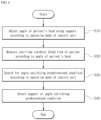
- FIG. 6 is a flowchart of a method for operating the cardiopulmonary resuscitation device according to some embodiments.
- the cardiopulmonary resuscitation device may adjust the angle of the head of the patient by using the support according to the operation mode of the control unit (S10). Specifically, as described with reference to FIGS. 1 to 5 , the control unit may adjust the angle of the support of the cardiopulmonary resuscitation board, thereby adjusting the angle of the head of the patient.
- the control unit may adjust the angle of the support of the cardiopulmonary resuscitation board, thereby adjusting the angle of the head of the patient.
- the real-time cerebral blood flow of the patient may be measured according to the angle of the head of the patient (S20). Specifically, when the head of the patient is positioned to have an angle according to the operation mode of the control unit, the real-time cerebral blood flow of the patient may be measured.
- an angle satisfying a predetermined condition according to the operation mode of the control unit may be searched for (S30). Specifically, it is possible to search for an angle satisfying a predetermined condition according to the first mode of the control unit or a predetermined condition according the second mode. Details thereof are described below with reference to FIG. 7 and FIG. 8 .
- FIG. 7 is a flowchart illustrating an operation mode of a control unit according to some embodiments. Specifically, FIG. 7 is a flowchart illustrating an operation of the control unit according to the first mode.
- the control unit may gradually increase the angle of the support (S51).
- the control unit may gradually increase the angle of the support from the minimum value of the preset angle range.
- the embodiment is not limited thereto.
- the control unit may gradually increase the angle of the support from a different value.
- control unit may measure the real-time cerebral blood flow of the patient at gradually increasing angles (S52).
- control unit may determine whether the real-time cerebral blood flow of the patient has a value greater than the target cerebral blood flow (S53).
- control unit may further increase the angle of the support.
- control unit may control the support to be fixed at the corresponding angle (S54).
- FIG. 8 is a flowchart illustrating an operation mode of the control unit according to other embodiments. Specifically, FIG. 8 is a flowchart illustrating an operation of the control unit according to the second mode.
- the control unit may adjust the angle of the head of the patient, that is, the angle of the support to correspond to a plurality of preset angles (S61). Since the plurality of preset angles are the same as those described with reference to FIG. 1 , detailed description thereof will be omitted.
- control unit may measure the real-time cerebral blood flow of the patient at the plurality of preset angles (S62).
- control unit may search for an angle at which the greatest increase in cerebral blood flow is exhibited among the real-time cerebral blood flows of the patient at the plurality of angles (S63).
- control unit may control the support to be fixed at an angle at which the greatest increase in cerebral blood flow is exhibited (S64).
Landscapes
- Health & Medical Sciences (AREA)
- Life Sciences & Earth Sciences (AREA)
- Veterinary Medicine (AREA)
- Public Health (AREA)
- General Health & Medical Sciences (AREA)
- Animal Behavior & Ethology (AREA)
- Heart & Thoracic Surgery (AREA)
- Pain & Pain Management (AREA)
- Rehabilitation Therapy (AREA)
- Physical Education & Sports Medicine (AREA)
- Epidemiology (AREA)
- Pulmonology (AREA)
- Emergency Medicine (AREA)
- Cardiology (AREA)
- Pathology (AREA)
- Biophysics (AREA)
- Physics & Mathematics (AREA)
- Engineering & Computer Science (AREA)
- Biomedical Technology (AREA)
- Medical Informatics (AREA)
- Molecular Biology (AREA)
- Surgery (AREA)
- Percussion Or Vibration Massage (AREA)
- Measuring Pulse, Heart Rate, Blood Pressure Or Blood Flow (AREA)
Abstract
Provided are a cardiopulmonary resuscitation device, and a method for operating the cardiopulmonary resuscitation device. The cardiopulmonary resuscitation device may comprise: a cardiopulmonary resuscitation board comprising a head support part, which includes a receiving portion formed concavely in order to support at least a portion of a patient's head, a support, which is disposed at the bottom of the head support pat and adjusts the angle of the patient's head, a backboard for supporting the patient's back, and a belt for securing the patient; a cerebral blood flow measurement device for measuring the real-time cerebral blood flow of the patient according to the angle of the patient's head; and a control unit for controlling to adjust the angle between the support and the backboard within a preset angle range on the basis of the measured cerebral blood flow of the patient.
Description
- The present disclosure relates to a cardiopulmonary resuscitation device and a method for operating the same. Specifically, the present disclosure relates to a cardiopulmonary resuscitation device capable of allowing a patient to take a head-up posture and performing emergency treatment based on cerebral blood flow measurement of the patient in the head-up posture, and a method for operating the cardiopulmonary resuscitation device.
- Acute cardiac arrest is one of the diseases that poses a large burden on public health due to its increasing incidence every year and low survival rate. According to the Korea Centers for Disease Control and Prevention (KCDC), the survival rate of psychogenic acute cardiac arrest in Korea increased from 2.3% in 2007 to 5.5% in 2017, and the brain function recovery rate thereof increased from 0.6% in 2007 to 3.1% in 2017. However, most patients with acute cardiac arrest still die or develop severe neurological disorders. In particular, only 3.0% of the patients survived prehospital cardiac arrest and only 0.9% of the patients neurologically recovered. Therefore, the posture of a patient during cardiopulmonary resuscitation in a cardiopulmonary resuscitation mode has become an important topic through several studies.
- Chest compression in the supine position, which is a standard cardiopulmonary resuscitation chest compression position, is commonly performed for cardiopulmonary resuscitation position. As the chest compression in the supine position for cardiopulmonary resuscitation is performed, the blood volume and the pressure in the arterial system and the right heart are increased and transmitted to the brain through the jugular vein and the paravertebral venous plexus, thereby increasing the intracranial pressure and decreasing the brain perfusion. Accordingly, the intracranial pressure is typically high in patients in a supine position, and patients with traumatic brain injury are typically subjected to a head-raising posture in a non-invasive manner to reduce the intracranial pressure.
- In other words, cardiopulmonary resuscitation in a head-up posture, which is the head-raising posture, increases the venous return from the brain to the heart by gravity, reduces the intracranial pressure, and improves the cardiac preload. In addition, several recent studies have shown that the head-up cardiopulmonary resuscitation reduces perfusion of the intracranial pressure, thereby increasing the cerebral perfusion pressure and the cerebral blood flow.
- Accordingly, there is a need for a cardiopulmonary resuscitation device that enables a patient with cardiac arrest to take a stable head-up posture and performs precise emergency treatment by measuring the cerebral blood flow of the patient in real time.
- The technical problem to be solved by the present disclosure is to provide a cardiopulmonary resuscitation device that enables a patient to take a stable head-up posture and performs precise emergency treatment by measuring the cerebral blood flow of the patient in real time.
- Another technical problem to be solved by the present disclosure is to provide a method for operating the cardiopulmonary resuscitation device that enables a patient to have a stable head-up posture and performs precise emergency treatment by measuring the cerebral blood flow of the patient in real time.
- The technical problems of the present disclosure are not limited to the above-mentioned technical problems, and other technical problems that are not mentioned will be clearly understood by those skilled in the art from the following description.
- A cardiopulmonary resuscitation device according to some embodiments for achieving the above technical problem may include: a cardiopulmonary resuscitation board including a head support part, which includes a receiving portion formed concavely in order to support at least a portion of a patient's head, a support, which is disposed at the bottom of the head support part and adjusts the angle of the patient's head, a backboard for supporting the patient's back, and a belt for securing the patient; a cerebral blood flow measurement device for measuring the real-time cerebral blood flow of the patient according to the angle of the patient's head; and a control unit for controlling to adjust the angle between the support and the backboard within a preset angle range on the basis of the measured cerebral blood flow of the patient.
- The preset angle range may be 10 degrees to 45 degrees.
- The control unit may operate in either a first mode or a second mode different from each other, and secure the support when the real-time cerebral blood flow of the patient satisfies a predetermined condition according to the mode of the control unit.
- When the control unit operates in the first mode, the control unit may adjust the support so that the angle between the support and the backboard gradually increases, and secure the support at a specific angle when the real-time cerebral blood flow of the patient at the specific angle has a value greater than a predetermined target cerebral blood flow.
- The predetermined target cerebral blood flow may be 1.15 times the real-time cerebral blood flow of the patient when the angle between the support and the backboard is 0 degree.
- When the control unit operates in the second mode, the control unit may adjust the support so that the angle between the support and the backboard corresponds to each of first to Nth angles within the preset angle range, and secure the support at an angle at which the greatest increase in cerebral blood flow is exhibited among the first to Nth angles, wherein an ith angle (i is a natural number between 2 and N) among the first to Nth angles may be greater than an i-1th angle, the first angle may be a minimum value of the preset angle range, and the Nth angle may be a maximum value of the preset angle range.
- The difference between the ith angle and the i-1th angle may have a constant value.
- The cerebral blood flow measurement device may include an inspection patch attached to an occipital region of the patient to obtain a cerebral blood flow signal.
- The cerebral blood flow measurement device may be a near-infrared spectroscopy (NIRS) device.
- A method for operating a cardiopulmonary resuscitation device according to some embodiments for accomplishing the above technical problem may include: adjusting an angle between a back of a patient and a head of the patient using a support, according to an operation mode of a control unit; measuring a real-time cerebral blood flow of the patient according to an angle of the head of the patient by using an inspection patch attached to the occipital region of the patient to obtain a cerebral blood flow signal; searching for an angle satisfying a predetermined condition according to an operation mode of the control unit; and securing the support at an angle satisfying the predetermined condition, wherein the searching for the angle satisfying the predetermined condition may be based on determining whether the measured real-time cerebral blood flow of the patient at least at any angle has a value greater than the predetermined cerebral blood flow.
- The angle between the patient's back and the patient's head may be adjusted between 10 degrees and 45 degrees.
- The predetermined target cerebral blood flow may be 1.15 times a real-time cerebral blood flow of the patient when the angle between the patient's back and the patient's head is 0 degree.
- The operation mode of the control unit may include: a first mode for adjusting the support so that the angle between the patient's back and the patient's head gradually increases; and a second mode for adjusting the support so that the angle between the patient's back and the patient's head corresponds to each of first to Nth angles within the preset angle range, wherein the ith angle (i is a natural number between 2 and N) among the first to Nth angles may be greater than the i-1th angle, the first angle may be a minimum value of the preset angle range, and the Nth angle may be a maximum value of the preset angle range.
- When the control unit operates in the second mode, the searching for an angle satisfying the predetermined condition may include searching for an angle at which the greatest increase in cerebral blood flow is exhibited among the first to Nth angles.
- The real-time cerebral blood flow of the patient may be measured by the NIRS device.
- The details of other embodiments are included in the detailed description and the drawings.
- According to some embodiments of the present disclosure, a cardiopulmonary resuscitation device and a method for operating the same may stably position a head of a patient higher than a heart of the patient to increase a brain perfusion pressure and a cerebral blood flow, thereby improving a neurological prognosis of the patient, and may measure a cerebral blood flow of the patient in real time according to an angle of the head of the patient, thereby determining a posture of the patient for effective cardiopulmonary resuscitation.
-
-
FIG. 1 is an exemplary block diagram of a cardiopulmonary resuscitation device according to some embodiments. -
FIG. 2 is an exemplary diagram of a cardiopulmonary resuscitation board according to some embodiments. -
FIG. 3 is an exemplary diagram of a receiving portion according to some embodiments. -
FIG. 4 is an exemplary diagram of a cerebral blood flow measurement device according to some embodiments. -
FIG. 5 is an exemplary diagram illustrating attachment locations of inspection patches according to some embodiments. -
FIG. 6 is a flowchart of a method for operating the cardiopulmonary resuscitation device according to some embodiments. -
FIG. 7 is a flowchart illustrating an operation mode of a control unit according to some embodiments. -
FIG. 8 is a flowchart illustrating an operation mode of the control unit according to other embodiments. - Hereinafter, preferred embodiments of the present disclosure will be described in detail with reference to the accompanying drawings. Advantages and features of the present disclosure, and methods for achieving the same, will become apparent by referring to the following detailed description of embodiments taken in conjunction with the accompanying drawings. However, the present disclosure is not limited to the embodiments disclosed below. The present disclosure may be implemented in various forms. The present embodiments are only provided to make the present disclosure complete and to fully convey the scope of the present disclosure to those skilled in the art. The present disclosure is only defined by the scope of the claims. The same reference numerals refer to the same components throughout the specification.
- The terminology used herein is only for describing the embodiments and is not intended to limit the present disclosure. As used herein, the singular forms include plural referents unless the context clearly dictates otherwise. As used herein, terms such as "comprises" and/or "comprising" do not exclude the presence or addition of one or more other components, steps, operations, and/or elements.
- Unless otherwise defined, all terms (including technical and scientific terms) used herein have the same meaning as commonly understood by those skilled in the art to which the present disclosure belongs. In addition, terms defined in commonly used dictionaries are not to be interpreted ideally or unduly unless explicitly defined.
- Hereinafter, embodiments of the present disclosure will be described in detail with reference to the accompanying drawings. In describing with reference to the drawings, the same or corresponding components will be denoted by the same reference numerals regardless of the drawing numbers, and repeated description thereof will be omitted.
-
FIG. 1 is an exemplary block diagram of a cardiopulmonary resuscitation device according to some embodiments. - Referring to
FIG. 1 , a cardiopulmonary resuscitation device 1 may include acardiopulmonary resuscitation board 10, a cerebral bloodflow measurement device 20, and acontrol unit 30. - The
cardiopulmonary resuscitation board 10 may allow a patient to assume a stable head-up posture during cardiopulmonary resuscitation through the various configurations described with reference toFIG. 2 . Details thereof are described with reference toFIG. 2 . - The cerebral blood
flow measurement device 20 may measure the patient's real-time cerebral blood flow. Specifically, the cerebral bloodflow measurement device 20 may measure the real-time cerebral blood flow of the patient according to an angle of the head of the patient. - The angle of the patient's head may refer to an angle between the patient's back and the patient's neck. Specifically, the angle of the patient's head may refer to an angle between the patient's back and the start of the neck toward the patient's shoulder when the patient's back is in close contact with the backboard of the
cardiopulmonary resuscitation board 10. - The cerebral blood
flow measurement device 20 may provide information on the measured real-time cerebral blood flow of the patient to thecontrol unit 30. - The
control unit 30 may control the operation of thecardiopulmonary resuscitation board 10 based on the measured cerebral blood flow of the patient. Specifically, thecontrol unit 30 may control thecardiopulmonary resuscitation board 10 to adjust the angle of the patient's head within a preset angle range. In this case, the preset angle range may be 10 degrees to 45 degrees, but the embodiment is not limited thereto. The preset angle range may be variously changed according to the embodiment. - More specifically, the
control unit 30 may receive information on the measured real-time cerebral blood flow of the patient from the cerebral bloodflow measurement device 20, and control thecardiopulmonary resuscitation board 10 to fix the angle of the patient's head to a specific angle when the real-time cerebral flow satisfies a predetermined condition according to an operation mode. - For example, the
control unit 30 may operate in either a first mode or a second mode. When thecontrol unit 30 operates in the first mode, thecontrol unit 30 may control thecardiopulmonary resuscitation board 10 so that the angle of the patient's head gradually increases. While thecontrol unit 30 operates in the first mode so that the angle of the head of the patient gradually increases, if the real-time cerebral blood flow of the patient at a specific angle has a value greater than the predetermined target cerebral blood flow, thecontrol unit 30 may control thecardiopulmonary resuscitation board 10 to be fixed at the corresponding specific angle. - On the other hand, the target cerebral blood flow may be 1.15 times greater than the real-time cerebral blood flow of the patient, for example, when the angle between the patient's back and the patient's head is 0 degree. However, the embodiments are not limited thereto. The target cerebral blood flow may be variously changed according to the embodiments.
- On the other hand, when the
control unit 30 operates in the second mode, thecontrol unit 30 may control thecardiopulmonary resuscitation board 10 so that the angle of the head of the patient corresponds to each of the first to Nth angles within the above-described preset angle range. While thecontrol unit 30 operates in the second mode so that the angle of the patient's head corresponds to each of the first through Nth angles, the cerebral blood flow of the patient at each angle may be measured by the cerebral bloodflow measurement device 20 at each angle. At this time, thecontrol unit 30 may control thecardiopulmonary resuscitation board 10 to be fixed at the angle at which the greatest increase in cerebral blood flow is exhibited among the first to Nth angles. - On the other hand, an ith angle (i is a natural number between 2 and N) among the first to Nth angles may be greater than the i-1th angle, the first angle may be a minimum value of the preset angle range, and the Nth angle may be a maximum value of the preset angular range. That is, when the preset angle range is 10 degrees to 45 degrees as described above, the first angle may refer to 10 degrees, and the Nth angle may refer to 45 degrees.
- In addition, a difference between the ith angle and the i-1th angle may have a constant value. For example, when the preset angle range has the above-described value and the difference between the ith angle and the i-1th angle is 5 degrees, the
control unit 30 may control thecardiopulmonary resuscitation board 10 so that the angle of the head of the patient corresponds to each of 10 degrees, 15 degrees, 20 degrees, 25 degrees, 30 degrees, 35 degrees, 40 degrees, and 45 degrees. - However, the embodiment is not limited thereto. The first to Nth angles may be variously changed according to the present angle range and the difference between the ith angle and the i-1th angle. For example, when the preset angle range is 15 degrees to 35 degrees and the difference between the ith angle and the i-1th angle is 10 degrees, the
control unit 30 may control thecardiopulmonary resuscitation board 10 so that the angle of the head of the patient corresponds to each of 15 degrees, 25 degrees, and 35 degrees. - Although
FIG. 1 shows that thecontrol unit 30 is separate from thecardiopulmonary resuscitation board 10 and the cerebral bloodflow measurement device 20, the embodiment is not limited thereto. For example, thecontrol unit 30 may be integrally formed by being mounted inside thecardiopulmonary resuscitation board 10 or may be integrally formed by being mounted inside the cerebral bloodflow measurement device 20. -
FIG. 2 is an exemplary diagram of a cardiopulmonary resuscitation board according to some embodiments. - Referring to
FIG. 2 , thecardiopulmonary resuscitation board 10 may include ahead support part 11, asupport 12, a backboard 13, ashoulder securing belt 14, and aforehead securing belt 15. - The
head support part 11 may be configured to support at least a part of the head of a patient P. Thehead support part 11 may be made of a fluffy material to minimize damage to the scalp even if the patient lies down for a long time of 30 minutes or more. Thehead support part 11 may include a receiving portion that is manufactured to be suitable for the head of a human body so that the occipital region can be suitably received in thehead support part 11. Details thereof are described with reference toFIG. 3 . - The
support 12 may be disposed below thehead support part 11 to adjust the angle of the head of the patient P. - The backboard 13 may support the back of the patient P. The backboard 13 may be configured to provide a firm repulsive force to the lower back of the patient during cardiopulmonary resuscitation.
- The
shoulder securing belt 14 may secure the shoulder of the patient P. Theforehead securing belt 15 may secure the head of the patient P. By using theshoulder securing belt 14 and theforehead securing belt 15 to firmly secure the head and other body parts of the patient P that may be shaken due to emergency treatment, the patient P may receive stable cardiopulmonary resuscitation. - Meanwhile, the
support 12 may adjust the angle of the head of the patient P under the control of thecontrol unit 30 ofFIG. 1 . Specifically, to increase the angle of the head of the patient P, thesupport 12 may increase the inclination of its surface in contact with thehead support part 11 under the control of thecontrol unit 30. To decrease the angle of the head of the patient P, thesupport 12 may decrease the inclination of its surface in contact with thehead support part 11 under the control of thecontrol unit 30. - Meanwhile, the angle of the head of the patient P may refer to an angle between the backboard 13 and the surface of the
support 12 in contact with thehead support part 11. That is, the angle between the backboard 13 and the surface of thesupport 12 in contact with thehead support part 11 may correspond to the angle between the back of the patient P and the neck of the patient P described with reference toFIG. 1 . -
FIG. 3 is an exemplary diagram of a receiving portion according to some embodiments. - Referring to
FIG. 3 , thehead support part 11 may include a receiving portion 11_1. Specifically, as illustrated inFIG. 3 (A) , thehead support part 11 may include the receiving portion 11_1 formed to be concave to support at least a part of the head of the patient P. Accordingly, as illustrated inFIG. 3 (B) , it is possible to provide an environment in which the patient P may take a stable posture through the receiving portion 11_1. On the other hand, the shape of the receiving portion 11_1 is not necessarily limited to the shape shown inFIG. 3 . Depending on the embodiment, the shape of the receiving portion 11_1 may be changed to various shapes capable of stably and appropriately supporting at least a part of the patient's head. -
FIG. 4 is an exemplary diagram of a cerebral blood flow measurement device according to some embodiments. - Referring to
FIG. 4 , the cerebral bloodflow measurement device 20 may include a cerebral bloodflow analysis device 21 and aninspection patch 22. - The cerebral blood
flow analysis device 21 may analyze a cerebral blood flow signal received from theinspection patch 22 to analyze the real-time cerebral blood flow of the patient P. In this case, the cerebral bloodflow analysis device 21 may analyze the cerebral blood flow using near-infrared spectroscopy (NIRS). However, the embodiment is not limited thereto. The cerebral bloodflow analysis device 21 may measure the cerebral blood flow of the patient P through any other appropriate methods according to the embodiment. In addition, the cerebral bloodflow analysis device 21 may use a micro light emitted diode (LED) to obtain an improved cerebral blood flow signal of the patient P, but the embodiment is not necessarily limited thereto. - The
inspection patch 22 may be attached to the skin of the patient P to obtain the cerebral blood flow signal. For example, theinspection patch 22 may be attached to the forehead of the patient P, or may be attached to the occipital region of the patient P. -
FIG. 5 is an illustrative diagram for describing attachment locations of inspection patches according to some embodiments. - Referring to
FIG. 5 , theinspection patch 22 may be attached not only to the forehead but also to the occipital region of the patient P. In the case of a general inspection patch attached to both sides of the forehead of the patient P to obtain a signal, there may be some problems in obtaining a signal from a patient receiving cardiopulmonary resuscitation, a patient with decreased consciousness, or a patient who is conscious, but has sweat or other causes that result in frequent poor adhesion. - However, the
inspection patch 22 according to some embodiments of the present disclosure may be attached to the occipital region of the patient P, which exhibits better adhesion than the forehead due to the weight of the head of the patient P. Accordingly, the cerebral blood flow signal of the patient P may be more effectively obtained. -
FIG. 6 is a flowchart of a method for operating the cardiopulmonary resuscitation device according to some embodiments. - Referring to
FIG. 6 , the cardiopulmonary resuscitation device may adjust the angle of the head of the patient by using the support according to the operation mode of the control unit (S10). Specifically, as described with reference toFIGS. 1 to 5 , the control unit may adjust the angle of the support of the cardiopulmonary resuscitation board, thereby adjusting the angle of the head of the patient. - Then, the real-time cerebral blood flow of the patient may be measured according to the angle of the head of the patient (S20). Specifically, when the head of the patient is positioned to have an angle according to the operation mode of the control unit, the real-time cerebral blood flow of the patient may be measured.
- Then, an angle satisfying a predetermined condition according to the operation mode of the control unit may be searched for (S30). Specifically, it is possible to search for an angle satisfying a predetermined condition according to the first mode of the control unit or a predetermined condition according the second mode. Details thereof are described below with reference to
FIG. 7 andFIG. 8 . - Then, the support may be fixed at an angle satisfying the predetermined condition (S40).
-
FIG. 7 is a flowchart illustrating an operation mode of a control unit according to some embodiments. Specifically,FIG. 7 is a flowchart illustrating an operation of the control unit according to the first mode. - Referring to
FIG. 7 , in the first mode, the control unit may gradually increase the angle of the support (S51). For example, the control unit may gradually increase the angle of the support from the minimum value of the preset angle range. However, the embodiment is not limited thereto. The control unit may gradually increase the angle of the support from a different value. - Then, the control unit may measure the real-time cerebral blood flow of the patient at gradually increasing angles (S52).
- Then, the control unit may determine whether the real-time cerebral blood flow of the patient has a value greater than the target cerebral blood flow (S53).
- If the real-time cerebral blood flow of the patient has a value smaller than the target cerebral blood flow (NO in S53), the control unit may further increase the angle of the support. On the other hand, when the real-time cerebral blood flow of the patient has a value greater than the target cerebral blood flow (Yes in S53), the control unit may control the support to be fixed at the corresponding angle (S54).
-
FIG. 8 is a flowchart illustrating an operation mode of the control unit according to other embodiments. Specifically,FIG. 8 is a flowchart illustrating an operation of the control unit according to the second mode. - Referring to
FIG. 8 , in the second mode, the control unit may adjust the angle of the head of the patient, that is, the angle of the support to correspond to a plurality of preset angles (S61). Since the plurality of preset angles are the same as those described with reference toFIG. 1 , detailed description thereof will be omitted. - Then, the control unit may measure the real-time cerebral blood flow of the patient at the plurality of preset angles (S62).
- Then, the control unit may search for an angle at which the greatest increase in cerebral blood flow is exhibited among the real-time cerebral blood flows of the patient at the plurality of angles (S63).
- Then, the control unit may control the support to be fixed at an angle at which the greatest increase in cerebral blood flow is exhibited (S64).
- Although the embodiments of the present disclosure have been described above with reference to the accompanying drawings, it should be understood that the present disclosure is not limited to the above embodiments but is manufactured in various different forms. Those skilled in the art may implement the present disclosure in other specific forms without modifying the technical concept or essential features of the present disclosure. It is therefore to be understood that the embodiments described above are illustrative and not restrictive in any respect.
-
- 1: Cardiopulmonary resuscitation device.
- 10: Cardiopulmonary resuscitation board.
- 11: Head support part
- 11_1: Receiving portion
- 12: Support
- 13: Backboard
- 14: Shoulder securing belt
- 15: Forehead securing belt
- 20: Cerebral blood flow measurement device
- 21: Cerebral blood flow analysis device
- 22: Inspection patch
- P: Patient
Claims (15)
- A cardiopulmonary resuscitation device comprising:a cardiopulmonary resuscitation board comprising a head support part, which comprises a receiving portion formed concavely in order to support at least a portion of a patient's head, a support, which is disposed at the bottom of the head support part and adjusts the angle of the patient's head, a backboard for supporting the patient's back, and a belt for securing the patient;a cerebral blood flow measurement device for measuring a real-time cerebral blood flow of the patient according to the angle of the patient's head; anda control unit for controlling to adjust the angle between the support and the backboard within a preset angle range on the basis of the measured cerebral blood flow of the patient.
- The cardiopulmonary resuscitation device of claim 1, wherein the preset angle range is 10 degrees to 45 degrees.
- The cardiopulmonary resuscitation device of claim 1, wherein the control unit operates in either a first mode or a second mode different from each other, and secures the support when the real-time cerebral blood flow of the patient satisfies a predetermined condition according to the mode of the control unit.
- The cardiopulmonary resuscitation device of claim 3, wherein, when the control unit operates in the first mode, the control unit adjusts the support so that the angle between the support and the backboard gradually increases, and secures the support at a specific angle when the real-time cerebral blood flow of the patient at the specific angle has a value greater than a predetermined target cerebral blood flow.
- The cardiopulmonary resuscitation device of claim 4, wherein the predetermined target cerebral blood flow is 1.15 times the real-time cerebral blood flow of the patient when the angle between the support and the backboard is 0 degree.
- The cardiopulmonary resuscitation device of claim 3, wherein, when the control unit operates in the second mode, the control unit adjusts the support so that the angle between the support and the backboard corresponds to each of first to Nth angles within the preset angle range, and secures the support at an angle at which the greatest increase in cerebral blood flow is exhibited among the first to Nth angles, wherein an ith angle (i is a natural number between 2 and N) among the first to Nth angles is greater than an i-1th angle, the first angle is a minimum value of the preset angle range, and the Nth angle is a maximum value of the preset angle range.
- The cardiopulmonary resuscitation device of claim 6, wherein a difference between the ith angle and the i-1th angle has a constant value.
- The cardiopulmonary resuscitation device of claim 1, wherein the cerebral blood flow measurement device comprises an inspection patch attached to an occipital region of the patient to obtain a cerebral blood flow signal.
- The cardiopulmonary resuscitation device claim 1, wherein the cerebral blood flow measurement device is a near-infrared spectroscopy (NIRS) device.
- A method for operating a cardiopulmonary resuscitation device, comprising:adjusting an angle between a back of a patient and a head of the patient using a support, according to an operation mode of a control unit;measuring a real-time cerebral blood flow of the patient according to an angle of the head of the patient by using an inspection patch attached to an occipital region of the patient to obtain a cerebral blood flow signal;searching for an angle satisfying a predetermined condition according to an operation mode of the control unit; andsecuring the support at an angle satisfying the predetermined condition,wherein the searching for an angle satisfying the predetermined condition is based on determining whether the measured real-time cerebral blood flow of the patient at least at any angle has a value greater than the predetermined cerebral blood flow.
- The method of claim 10, wherein the angle between the back and the head of the patient is adjusted between 10 degrees and 45 degrees.
- The method of claim 10, wherein the predetermined target cerebral blood flow is 1.15 times the real-time cerebral blood flow of the patient when the angle between the patient's back and the patient's head is 0 degree.
- The method of claim 10, wherein the operation mode of the control unit comprises:a first mode for adjusting the support so that the angle between the back and the head of the patient gradually increases; anda second mode for adjusting the support so that the angle between the back andthe head of the patient corresponds to each of first to Nth angles within the preset angle range,wherein an ith angle (i is a natural number between 2 and N) among the first to Nth angles is greater than an i-1th angle, the first angle is a minimum value of the preset angle range, and the Nth angle is a maximum value of the preset angle range.
- The method of claim 13, wherein, when the control unit operates in the second mode, the searching for an angle satisfying the predetermined condition comprises searching for an angle at which the greatest increase in cerebral blood flow is exhibited among the first to Nth angles.
- The method of claim 10, wherein the real-time cerebral blood flow of the patient is measured by a near-infrared spectroscopy (NIRS) device.
Applications Claiming Priority (2)
| Application Number | Priority Date | Filing Date | Title |
|---|---|---|---|
| KR1020220101391A KR102916258B1 (en) | 2022-08-12 | 2022-08-12 | Head up cardiopulmonary resuscitation device based on measurement of cerebral blood flow and method for operating thereof |
| PCT/KR2023/011672 WO2024035073A1 (en) | 2022-08-12 | 2023-08-08 | Head-up cardiopulmonary resuscitation device based on cerebral blood flow measurement, and method for operating same |
Publications (1)
| Publication Number | Publication Date |
|---|---|
| EP4570228A1 true EP4570228A1 (en) | 2025-06-18 |
Family
ID=89852012
Family Applications (1)
| Application Number | Title | Priority Date | Filing Date |
|---|---|---|---|
| EP23852945.7A Pending EP4570228A1 (en) | 2022-08-12 | 2023-08-08 | Head-up cardiopulmonary resuscitation device based on cerebral blood flow measurement, and method for operating same |
Country Status (4)
| Country | Link |
|---|---|
| US (1) | US20260041604A1 (en) |
| EP (1) | EP4570228A1 (en) |
| KR (1) | KR102916258B1 (en) |
| WO (1) | WO2024035073A1 (en) |
Family Cites Families (7)
| Publication number | Priority date | Publication date | Assignee | Title |
|---|---|---|---|---|
| JP2007147604A (en) * | 2005-11-01 | 2007-06-14 | Action Research:Kk | Positron emission tomographic imaging system, and vibration exhibition device used therefor |
| EP3107516B1 (en) | 2014-02-19 | 2022-10-05 | Keith G. Lurie | Systems and methods for gravity-assisted cardiopulmonary resuscitation |
| US12144777B2 (en) * | 2014-02-19 | 2024-11-19 | Resuscitation Innovations Llc | Methods and systems to reduce brain damage |
| KR101596011B1 (en) * | 2014-11-26 | 2016-02-19 | 주식회사 비엠텍월드와이드 | System for measuring brain blood flow automatically |
| US12285383B2 (en) * | 2016-10-21 | 2025-04-29 | Zoll Medical Corporation | System and methods for adaptive body positioning during chest compressions |
| US12201561B2 (en) | 2020-03-31 | 2025-01-21 | Michael Fonte | Elevated CPR assist device and method |
| CN214202735U (en) | 2021-01-11 | 2021-09-14 | 重庆医药高等专科学校附属第一医院(重庆市职业病防治院、重庆市第六人民医院、重庆市中毒控制中心) | Medical external chest compression training device |
-
2022
- 2022-08-12 KR KR1020220101391A patent/KR102916258B1/en active Active
-
2023
- 2023-08-08 EP EP23852945.7A patent/EP4570228A1/en active Pending
- 2023-08-08 US US19/102,852 patent/US20260041604A1/en active Pending
- 2023-08-08 WO PCT/KR2023/011672 patent/WO2024035073A1/en not_active Ceased
Also Published As
| Publication number | Publication date |
|---|---|
| KR102916258B1 (en) | 2026-01-22 |
| US20260041604A1 (en) | 2026-02-12 |
| KR20240022846A (en) | 2024-02-20 |
| WO2024035073A1 (en) | 2024-02-15 |
Similar Documents
| Publication | Publication Date | Title |
|---|---|---|
| US11883197B1 (en) | Head-mounted physiological signal monitoring system, devices and methods | |
| US12239423B2 (en) | Detection of patient conditions using signals sensed on or near the head | |
| Kabat et al. | Acute arrest of cerebral circulation in man: Lieutenant Ralph Rossen (MC), USNR | |
| EP3177201B1 (en) | Methods and systems for assessing neural activity in an eye | |
| RU2548791C2 (en) | Non-invasive method and device for determination of stages of superficial and deep sleep | |
| US10149624B2 (en) | Method and device for measuring intracranial pressure, ICP, in a subject | |
| US20060195035A1 (en) | Non-invasive radial artery blood pressure waveform measuring apparatus system and uses thereof | |
| US20060217615A1 (en) | Determination of clinical stress of a subject in pulse oximetry | |
| US20020024633A1 (en) | Pupil evaluation system | |
| US20180368699A1 (en) | System of predicting dementia and operating method thereof | |
| O'Leary et al. | Vestibular autorotation testing of Meniere's disease | |
| JP2002514449A (en) | Electrophysiological perimetry | |
| CN114795144A (en) | A digital smart glasses that enhances brain intelligence | |
| US20260041604A1 (en) | Head-up cardiopulmonary resuscitation device based on cerebral blood flow measurement, and method for operating same | |
| Ferini-Strambi et al. | Cardiac autonomic function during sleep and wakefulness in multiple sclerosis | |
| US12414725B2 (en) | Method and apparatus for detecting changes in blood flow in the head of a subject | |
| Fenwick et al. | Estimates of brain activity using magnetic field tomography in a GO/NOGO avoidance paradigm | |
| RU2114772C1 (en) | Device for study of vestibular analyzer under conditions of simulated zero-g conditions | |
| CN116056638B (en) | Detecting patient condition using sensed signals on or near the head | |
| Hetlof et al. | Evaluation of the effect of flights in supersonic fighters on sinus rhythm variability parameters | |
| Faskhodi et al. | On the Application of Short-Term Heart Rate Variability Indices to Track Changes in Cognitive Arousal. | |
| RU2768446C2 (en) | Method for assessing state of autonomic nervous system of person by heart rate | |
| Juhola et al. | A signal analysis technique of vestibulo-ocular reflex stimulated with impulsive head movements | |
| Shender | Rheoencephalography in simulated aviation environmental stress | |
| KR20250060663A (en) | Smart stress prediction and relief system using non-contact stress resistance index measurement |
Legal Events
| Date | Code | Title | Description |
|---|---|---|---|
| STAA | Information on the status of an ep patent application or granted ep patent |
Free format text: STATUS: THE INTERNATIONAL PUBLICATION HAS BEEN MADE |
|
| PUAI | Public reference made under article 153(3) epc to a published international application that has entered the european phase |
Free format text: ORIGINAL CODE: 0009012 |
|
| STAA | Information on the status of an ep patent application or granted ep patent |
Free format text: STATUS: REQUEST FOR EXAMINATION WAS MADE |
|
| 17P | Request for examination filed |
Effective date: 20250211 |
|
| AK | Designated contracting states |
Kind code of ref document: A1 Designated state(s): AL AT BE BG CH CY CZ DE DK EE ES FI FR GB GR HR HU IE IS IT LI LT LU LV MC ME MK MT NL NO PL PT RO RS SE SI SK SM TR |
|
| DAV | Request for validation of the european patent (deleted) | ||
| DAX | Request for extension of the european patent (deleted) |