EP4570212A1 - Force and torque jig - Google Patents
Force and torque jig Download PDFInfo
- Publication number
- EP4570212A1 EP4570212A1 EP24220033.5A EP24220033A EP4570212A1 EP 4570212 A1 EP4570212 A1 EP 4570212A1 EP 24220033 A EP24220033 A EP 24220033A EP 4570212 A1 EP4570212 A1 EP 4570212A1
- Authority
- EP
- European Patent Office
- Prior art keywords
- axis
- distal end
- catheter
- end assembly
- base
- Prior art date
- Legal status (The legal status is an assumption and is not a legal conclusion. Google has not performed a legal analysis and makes no representation as to the accuracy of the status listed.)
- Pending
Links
Images


Classifications
-
- A—HUMAN NECESSITIES
- A61—MEDICAL OR VETERINARY SCIENCE; HYGIENE
- A61M—DEVICES FOR INTRODUCING MEDIA INTO, OR ONTO, THE BODY; DEVICES FOR TRANSDUCING BODY MEDIA OR FOR TAKING MEDIA FROM THE BODY; DEVICES FOR PRODUCING OR ENDING SLEEP OR STUPOR
- A61M25/00—Catheters; Hollow probes
-
- A—HUMAN NECESSITIES
- A61—MEDICAL OR VETERINARY SCIENCE; HYGIENE
- A61B—DIAGNOSIS; SURGERY; IDENTIFICATION
- A61B18/00—Surgical instruments, devices or methods for transferring non-mechanical forms of energy to or from the body
- A61B18/04—Surgical instruments, devices or methods for transferring non-mechanical forms of energy to or from the body by heating
- A61B18/12—Surgical instruments, devices or methods for transferring non-mechanical forms of energy to or from the body by heating by passing a current through the tissue to be heated, e.g. high-frequency current
-
- A—HUMAN NECESSITIES
- A61—MEDICAL OR VETERINARY SCIENCE; HYGIENE
- A61B—DIAGNOSIS; SURGERY; IDENTIFICATION
- A61B90/00—Instruments, implements or accessories specially adapted for surgery or diagnosis and not covered by any of the groups A61B1/00 - A61B50/00, e.g. for luxation treatment or for protecting wound edges
- A61B90/06—Measuring instruments not otherwise provided for
-
- A—HUMAN NECESSITIES
- A61—MEDICAL OR VETERINARY SCIENCE; HYGIENE
- A61B—DIAGNOSIS; SURGERY; IDENTIFICATION
- A61B5/00—Measuring for diagnostic purposes; Identification of persons
- A61B5/145—Measuring characteristics of blood in vivo, e.g. gas concentration or pH-value ; Measuring characteristics of body fluids or tissues, e.g. interstitial fluid or cerebral tissue
- A61B5/1495—Calibrating or testing of in-vivo probes
-
- A—HUMAN NECESSITIES
- A61—MEDICAL OR VETERINARY SCIENCE; HYGIENE
- A61B—DIAGNOSIS; SURGERY; IDENTIFICATION
- A61B5/00—Measuring for diagnostic purposes; Identification of persons
- A61B5/68—Arrangements of detecting, measuring or recording means, e.g. sensors, in relation to patient
- A61B5/6846—Arrangements of detecting, measuring or recording means, e.g. sensors, in relation to patient specially adapted to be brought in contact with an internal body part, i.e. invasive
- A61B5/6847—Arrangements of detecting, measuring or recording means, e.g. sensors, in relation to patient specially adapted to be brought in contact with an internal body part, i.e. invasive mounted on an invasive device
- A61B5/6852—Catheters
-
- A—HUMAN NECESSITIES
- A61—MEDICAL OR VETERINARY SCIENCE; HYGIENE
- A61B—DIAGNOSIS; SURGERY; IDENTIFICATION
- A61B18/00—Surgical instruments, devices or methods for transferring non-mechanical forms of energy to or from the body
- A61B2018/00053—Mechanical features of the instrument of device
- A61B2018/00214—Expandable means emitting energy, e.g. by elements carried thereon
- A61B2018/00267—Expandable means emitting energy, e.g. by elements carried thereon having a basket shaped structure
-
- A—HUMAN NECESSITIES
- A61—MEDICAL OR VETERINARY SCIENCE; HYGIENE
- A61B—DIAGNOSIS; SURGERY; IDENTIFICATION
- A61B18/00—Surgical instruments, devices or methods for transferring non-mechanical forms of energy to or from the body
- A61B2018/00315—Surgical instruments, devices or methods for transferring non-mechanical forms of energy to or from the body for treatment of particular body parts
- A61B2018/00345—Vascular system
- A61B2018/00351—Heart
-
- A—HUMAN NECESSITIES
- A61—MEDICAL OR VETERINARY SCIENCE; HYGIENE
- A61B—DIAGNOSIS; SURGERY; IDENTIFICATION
- A61B18/00—Surgical instruments, devices or methods for transferring non-mechanical forms of energy to or from the body
- A61B2018/00571—Surgical instruments, devices or methods for transferring non-mechanical forms of energy to or from the body for achieving a particular surgical effect
- A61B2018/00577—Ablation
-
- A—HUMAN NECESSITIES
- A61—MEDICAL OR VETERINARY SCIENCE; HYGIENE
- A61B—DIAGNOSIS; SURGERY; IDENTIFICATION
- A61B18/00—Surgical instruments, devices or methods for transferring non-mechanical forms of energy to or from the body
- A61B2018/00636—Sensing and controlling the application of energy
- A61B2018/00773—Sensed parameters
-
- A—HUMAN NECESSITIES
- A61—MEDICAL OR VETERINARY SCIENCE; HYGIENE
- A61B—DIAGNOSIS; SURGERY; IDENTIFICATION
- A61B90/00—Instruments, implements or accessories specially adapted for surgery or diagnosis and not covered by any of the groups A61B1/00 - A61B50/00, e.g. for luxation treatment or for protecting wound edges
- A61B90/06—Measuring instruments not otherwise provided for
- A61B2090/064—Measuring instruments not otherwise provided for for measuring force, pressure or mechanical tension
-
- A—HUMAN NECESSITIES
- A61—MEDICAL OR VETERINARY SCIENCE; HYGIENE
- A61B—DIAGNOSIS; SURGERY; IDENTIFICATION
- A61B90/00—Instruments, implements or accessories specially adapted for surgery or diagnosis and not covered by any of the groups A61B1/00 - A61B50/00, e.g. for luxation treatment or for protecting wound edges
- A61B90/06—Measuring instruments not otherwise provided for
- A61B2090/064—Measuring instruments not otherwise provided for for measuring force, pressure or mechanical tension
- A61B2090/065—Measuring instruments not otherwise provided for for measuring force, pressure or mechanical tension for measuring contact or contact pressure
-
- A—HUMAN NECESSITIES
- A61—MEDICAL OR VETERINARY SCIENCE; HYGIENE
- A61B—DIAGNOSIS; SURGERY; IDENTIFICATION
- A61B2560/00—Constructional details of operational features of apparatus; Accessories for medical measuring apparatus
- A61B2560/02—Operational features
- A61B2560/0223—Operational features of calibration, e.g. protocols for calibrating sensors
-
- A—HUMAN NECESSITIES
- A61—MEDICAL OR VETERINARY SCIENCE; HYGIENE
- A61B—DIAGNOSIS; SURGERY; IDENTIFICATION
- A61B2560/00—Constructional details of operational features of apparatus; Accessories for medical measuring apparatus
- A61B2560/06—Accessories for medical measuring apparatus
- A61B2560/063—Devices specially adapted for delivering implantable medical measuring apparatus
- A61B2560/066—Devices specially adapted for delivering implantable medical measuring apparatus catheters therefor
-
- A—HUMAN NECESSITIES
- A61—MEDICAL OR VETERINARY SCIENCE; HYGIENE
- A61B—DIAGNOSIS; SURGERY; IDENTIFICATION
- A61B5/00—Measuring for diagnostic purposes; Identification of persons
- A61B5/68—Arrangements of detecting, measuring or recording means, e.g. sensors, in relation to patient
- A61B5/6846—Arrangements of detecting, measuring or recording means, e.g. sensors, in relation to patient specially adapted to be brought in contact with an internal body part, i.e. invasive
- A61B5/6885—Monitoring or controlling sensor contact pressure
-
- A—HUMAN NECESSITIES
- A61—MEDICAL OR VETERINARY SCIENCE; HYGIENE
- A61M—DEVICES FOR INTRODUCING MEDIA INTO, OR ONTO, THE BODY; DEVICES FOR TRANSDUCING BODY MEDIA OR FOR TAKING MEDIA FROM THE BODY; DEVICES FOR PRODUCING OR ENDING SLEEP OR STUPOR
- A61M2205/00—General characteristics of the apparatus
- A61M2205/70—General characteristics of the apparatus with testing or calibration facilities
Definitions
- This disclosure relates generally to catheterization, and specifically to calibrating a catheter.
- contact force between an electrode and tissue being ablated is an important parameter for both pulse-field ablation (PFA) and radiofrequency (RF) ablation.
- PFA pulse-field ablation
- RF radiofrequency
- Pulse-field ablation (PFA) and radiofrequency (RF) ablation are cardiac procedures, using a catheter, that may be used to restore a heart to its sinus rhythm.
- a physician manipulates the catheter so that electrodes on the catheter distal end contact selected sites within the heart, and when contact is achieved, the ablation may be activated.
- a catheter having a distal end assembly with multiple electrodes such as a catheter with a basket or a balloon distal end, herein termed a basket-type catheter, so that multiple sites may be contacted simultaneously.
- a catheter having a distal end assembly with multiple electrodes such as a catheter with a basket or a balloon distal end, herein termed a basket-type catheter, so that multiple sites may be contacted simultaneously.
- the electrodes may be activated simultaneously.
- the distal end assembly of a basket-type catheter may be inserted into the heart by a minimally invasive method, such as insertion through a femoral artery.
- the physician manipulates the proximal end of the catheter shaft to position the assembly at a desired location and to engage the electrodes against the tissue with a desired force. While the electrodes are engaged with the tissue, manipulation of the proximal end may exert a torque on the distal end assembly. Since the distal end assembly is flexible, the torque may lead to twisting of the distal end assembly.
- the inventors have observed that in some cases the applied torque may be followed by the distal end assembly untwisting relatively suddenly, possibly causing trauma to the heart tissue and/or interfering with performance of an ablation.
- the distal end assembly includes three-dimensional (3D) position sensors that enable the orientation of the assembly to be measured with respect to the catheter shaft to which the assembly is attached.
- An example of the present disclosure provides a jig which is able to measure positions of the 3D sensors of the assembly, so as to measure the twist of the assembly.
- the jig is able to apply a force and a torque to the distal end assembly, and in addition is able to measure the force and the torque applied.
- the data acquired from the jig enables a correspondence to be formed between the orientation of the assembly with respect to the catheter shaft and the force and torque applied to the distal end assembly.
- this correspondence may be used to find the force and the torque on a basket-type catheter distal end assembly used in the procedure.
- Knowledge of the value of the torque enables a warning to be issued if the torque exceeds a preset limit, so as to prevent sudden untwisting of the catheter distal end assembly during the procedure.
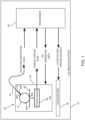
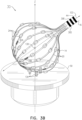
- Figs. 1 , 2 , and 3A and 3B are respectively a schematic block diagram of a calibration system 10, schematic figures of the system, and schematic figures of a catheter distal end assembly 14 used in the calibration system, according to an example of the present disclosure.
- Distal end assembly 14 is attached to a shaft 16 of a catheter 18, and in Fig. 2 and Figs. 3A and 3B, distal end 14 is shown as a basket, having a plurality of generally similar splines 20 upon which are mounted generally similar electrodes 24. (In Fig.
- distal end assembly 14 is shown schematically as a circle.
- other distal end assemblies may be in the form of a balloon, so that distal end assembly 14 may also be referred to herein as basket 14 or balloon 14, and catheter 18 is also referred to as basket-type catheter 18.
- System 10 comprises a jig 22, and two views of the jig are shown in Fig. 2 .
- the views are drawn on xyz Cartesian axes, described further below.
- Jig 22 holds distal end assembly 14 and is operable to selectively deflect, twist and/or press distal end assembly 14 in a defined manner.
- a 3D strain gauge senses the applied strain due to the selective maneuvering of the distal end assembly and a location pad 26 is used to enable measurement of locations and orientations of sensors 30A, 30B, 30C, mounted on a distal section of distal end assembly 14, and of sensors 30D and 30E, mounted on the distal end of shaft 16.
- Sensors 30A, 30B, 30C, 30D, and 30E are also referred to herein as sensors 30, and each sensor generates respective signals indicative of the location and orientation of the sensor.
- Sensors 30 are typically single axis sensors (SASs), but in some examples at least some of sensors 30 may comprise double axis sensors (DASs) and/or triple axis sensors (TASs). Sensors 30, together with location pad 26, are used for magnetic based position sensing, and details of magnetic based position sensing technology, which uses radiating alternating magnetic fields, are described in U.S. Patent Nos. 5,5391,199 ; 5,443,489 ; 5,558,091 ; 6,172,499 ; 6,239,724 ; 6,332,089 ; 6,484,118 ; 6,618,612 ; 6,690,963 ; 6,788,967 ; and 6,892,091 .
- Location pad 26 comprises a plurality of generally similar magnetic coils 28 each configured for generating a magnetic field, and in the present example there are three coils 28, two of which are visible in Fig. 2 .
- the magnetic field from coils 28 induces a signal in sensors 30, and the signals from the sensors are used, as described below, to ascertain the position of each of sensors 30.
- a magnetic coil 44 configured for generating a magnetic field is located on the distal end of shaft 16, and sensors 30A, 30B, and 30C are configured to sense their location and orientation relative to coil 44, in response to a signal induced in the sensors due to the presence of the generated magnetic field from coil 44.
- signals may be induced on each of sensors 30A, 30B, 30C, 30D and 30E based on magnetic fields generated from coils 28 on the location pad.
- Each of the coils may be configured to generate a magnetic field in a dedicated AC frequency so that the signals induced on sensors 30A, 30B, 30C, 30D and 30E from the different generating coils may be differentiated.
- a processor 34 transmits data for operating jig 22, as well as driving signals for the location pad.
- the processor receives force related data from the 3D strain gauge 36 in the jig, and in a disclosed example the strain gauge is also configured to provide torque related data to the processor.
- a separate torque-gauge 40 provides torque data to the processor.
- a relationship between strain and force (and/or torque) may be stored in memory associated with processor 34.
- the processor also receives location and orientation data of each of sensors 30 via the position signals of the respective sensors, and the processor forms a correspondence between the two sets of data, i.e., between the force and torque data and the deflection of distal end assembly based on sensed location and orientation data.
- the correspondence may be used to find the force and torque on the distal end assembly of a basket-type catheter for different shaped deflections of the distal end assembly, for the same type of catheters used in a medical procedure.
- strain gauge 36 provides force related data to processor 34.
- Jig 22 comprises three actuators, which are controlled by processor 34, and which are used to selectively twist and deflect the distal end assembly.
- the actuators are assumed to comprise motors, but those having ordinary skill in the art will be aware of other types of actuators, such as linear translators or cables, and all such actuators are assumed to be comprised within the scope of the present disclosure.
- a first actuator 38 also herein termed motor 38, is mounted on a fixed base 42 of the jig, and drives a cam 46.
- An inset 48 illustrates motor 38 and cam 46.
- Cam 46 mates with pad 58 mounted on a moveable base 54, via a contact 58 embedded in the upper side of base 54, and the moveable base operates as a class 1 lever, and is also herein termed lever 54.
- Embedded in the underside of base 54 are two supports 62, which contact fixed base 42, and which act as a fulcrum for base 54 when the base operates as a lever.
- rotation of cam 46 by motor 38 provides a lever-effort to a section 66 of base 54, surrounding pad 58, pushing the section to move approximately linearly in a vertical direction.
- section 70 As section 66 is moved linearly, a section 70 of base 54, on the opposite side of supports 62 to section 66, also moves approximately linearly and vertically, in the opposite direction to section 66, because base 54 acts as a lever. Thus, when a lever-effort is applied to section 66, a corresponding lever-load is produced on section 70.
- Section 70 mates with a strain gauge support bar 74, which in turn moves vertically, parallel to the z-axis, by being constrained to travel in vertical grooves 78, 82 in respective frame-supports 86, 90.
- Frame-supports 86, 90 are fixedly connected to fixed base 42 at its upper side.
- Strain gauge support bar 74 supports strain gauge 36, which is connected on an upper surface of the cell to platform 50. The connection is configured so that strain gauge 36 provides force-signals corresponding to the vector force acting on platform 50. When implemented to measure torque, strain gauge 36 also provides torque-signals corresponding to the torque around the z-axis acting on the platform.
- a second actuator 94 also herein termed motor 94, is mounted on frame-support 86 of the jig, and on operation is configured to rotate a frame 98 about an axis 102, parallel to the x-axis, passing through frame-supports 86 and 90. Since frame-supports 86 and 90 are fixed to base 42, axis 102 does not move with respect to the base. As is explained further below, rotation of frame 98 rotates distal end assembly 14 about axis of rotation 102, and the axis is configured to pass approximately through the center of the distal end assembly. Motor 94 uses a gear train 106 to rotate frame 98. As is illustrated, weights 110 are attached to frame 98, the weights being selected so that the frame is "balanced" around axis 102.
- a third actuator 114 also herein termed motor 114, is mounted on frame 98. Also mounted on frame 98 is a catheter clamping assembly 118 that acts as a catheter support and that is configured to grip shaft 16 of catheter 18, and to rotate the shaft about an axis 122 defined by, and congruent with, shaft 16.
- a torque-gauge 40 is connected to assembly 118, and is configured to measure torque of shaft 16 about axis 122 when the shaft is rotated by actuator 114.
- Axis 122 is orthogonal to axis 102.
- Actuator 114 is coupled to clamping assembly 118 by a gear train 126, so that operation of actuator 114 causes shaft 16 of catheter 18 to rotate about the shaft, i.e., about axis 122.
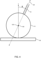
- Fig. 4 is a schematic figure illustrating the relation between the z-axis, axis 102, and axis 122, according to an example of the present disclosure.
- distal end assembly 14 has been drawn schematically as a circle.
- the z-axis and axis 122 lie in the plane of the paper, and axis 102 is orthogonal to the plane of the paper.
- all three axes, the z-axis, axis 102, and axis 122 intersect at a common point 130.
- Jig 22 is configured so that common point 30 is approximately at the center of distal end assembly 14.
- jig when shaft 16 is gripped by clamping assembly 118, the jig may be considered to be in a "null" position wherein frame 98 is adjusted so that shaft 16 aligns with the z-axis. This is illustrated in Fig. 3A . Rotation of frame 98 about axis 102, from the null position, rotates distal end assembly 14 about axis 102, so that shaft 16 no longer aligns with the z-axis. A typical rotation is illustrated in Fig. 3B .
- distal end assembly 14 may be translated and/or compressed along the z-axis, and may be rotated about axis 102 and axis 122.
- platform 50 is configured to have a plurality of pillars 134 protruding from the platform. In the illustrated example there are three pillars 134 close to the center of platform 50, but other examples may have other numbers for the plurality, and/or other positions for the pillars.
- pillars 134 may be configured to interlock with the splines, as is illustrated in Fig. 3 . Such interlocking prevents distal end assembly 14 from moving laterally, while still allowing the distal end assembly to be rotated, twisted, and/or compressed by the actions of actuators 38, 94, and 114.
- pillars 134 may be moved further from the center of platform 50, so as to grip the balloon while still permitting rotation, twisting and/or compression of the balloon under the actions of the actuators.
- processor 34 provides jig settings to jig 22, comprising settings for actuators 38, 94, and 114.
- Processor 34 also provides driving signals to coils 28 of location pad 26, and to coil 44.
- Processor 34 receives location and orientation signals from sensors 30 generated in response to their received magnetic radiations.
- the processor receives force signals from strain gauge 36, indicative of the magnitude and the direction, in three dimensions (3D), of the force from distal end assembly 14 on the strain gauge.
- Strain gauge 36 also provides the processor with signals indicative of the torque about the z-axis on the strain gauge, that is generated by distal end assembly 14.
- the processor is able to determine the force and the torque exerted on pillars 134 of platform 50 due to twisting of the distal end assembly.
- Actuator 114 twists shaft 16 about axis 122, and the splines of the distal end assembly apply a torque on pillars 134, around the z-axis. This is the torque that is measured.
- processor 34 is able to develop a correspondence between, on the one hand the positions of sensors 30, and on the other hand the 3D force on distal end assembly 14 and the torque around catheter shaft 16.
- the correspondence may be generated from a lookup table of the raw data received when system 10 is operated.
- the correspondence may be generated by fitting the raw data to a model applied to the distal end assembly, so as to find parameters of the model.
- splines 20 are elastic, and the model is assumed to be an elastic model.
- the correspondence may then be used to find the force and the torque of catheters other than catheter 18, when such catheters are used in a procedure. During the procedure, if the value of the torque is at a preset value, above which there may be the possibility that the distal end assembly may untwist suddenly, a warning that the preset value has been attained may be issued.
- Example 1 Apparatus for calibrating a catheter (18), comprising:
- Example 2 The apparatus according to example 1, and comprising an actuator, coupled to the frame, configured to rotate the frame about the second axis.
- Example 3 The apparatus according to example 1, and comprising an actuator, coupled to the frame, configured to rotate the catheter about the third axis.
- Example 4 The apparatus according to example 1, and comprising an actuator, coupled to the base, configured to provide the translation of the distal end assembly along the first axis.
- Example 5 The apparatus according to example 4, and comprising a moveable base configured to act as a lever, and wherein the actuator is configured to exert an effort on the moveable base so as to exert the force on the distal end assembly.
- Example 6 The apparatus according to example 5, wherein the moveable base is configured as a class 1 lever.
- Example 7 The apparatus according to example 5, and comprising a cam coupled to the moveable base, and wherein the actuator is configured to rotate the cam so as exert the effort.
- Example 8 The apparatus according to example 1, and comprising a platform, connecting the gauge to the distal end assembly, configured to support the distal end assembly.
- Example 9 The apparatus according to example 8, comprising a plurality of pins, protruding from the platform, configured to retain the distal end assembly in a preset position on the platform.
- Example 10 The apparatus according to example 1, and comprising a location pad, positioned in proximity to the base, configured to transmit electromagnetic radiation to the catheter and the distal end assembly, and wherein the electromagnetic radiation is configured to generate a signal in at least one sensor connected to at least one of the catheter and the distal end assembly, wherein the signal is indicative of a position of the at least one sensor.
- Example 11 The apparatus according to example 1, wherein the gauge is configured to provide a further indication of a torque on the distal end assembly around the first axis in response to rotation of the catheter about the third axis.
- Example 12 The apparatus according to example 11, and comprising a processor, configured to calculate an angle between the first axis and the third axis, and to calculate a further torque on the distal end assembly around the third axis in response to the angle and the indication of the torque around the first axis.
- Example 14 The apparatus according to example 1, and comprising a torque-gauge, coupled to the catheter support, configured to provide a further indication of a torque about the third axis in response to rotation of the catheter about the third axis.
- Example 15 A method for calibrating a catheter (18), comprising:
- Example 16 The method according to example 15, and comprising coupling an actuator to the frame and configuring the actuator to rotate the frame about the second axis.
- Example 17 The method according to example 15, and comprising coupling an actuator to the frame, and configuring the actuator to rotate the catheter about the third axis.
- Example 18 The method according to example 15, and comprising coupling an actuator to the base, and configuring the actuator to provide the translation of the distal end assembly along the first axis.
- Example 19 The method according to example 18, and comprising configuring a moveable base to act as a lever, and wherein the actuator is configured to exert an effort on the moveable base so as to exert the force on the distal end assembly.
- Example 20 The method according to example 19, wherein the moveable base is configured as a class 1 lever.
- Example 21 The method according to example 19, and comprising coupling a cam to the moveable base, and wherein the actuator is configured to rotate the cam so as exert the effort.
- Example 22 The method according to example 15, and comprising connecting the gauge to the distal end assembly by a platform configured to support the distal end assembly.
- Example 23 The method according to example 22, and comprising providing a plurality of pins, protruding from the platform, configured to retain the distal end assembly in a preset position on the platform.
- Example 24 The method according to example 15, and comprising positioning a location pad in proximity to the base, and configuring the pad to transmit electromagnetic radiation to the catheter and the distal end assembly, and wherein the electromagnetic radiation is configured to generate a signal in at least one sensor connected to at least one of the catheter and the distal end assembly, wherein the signal is indicative of a position of the at least one sensor.
- Example 25 The method according to example 15, wherein the gauge is configured to provide a further indication of a torque on the distal end assembly around the first axis in response to rotation of the catheter about the third axis.
- Example 26 The method according to example 25, and comprising calculating an angle between the first axis and the third axis, and calculating a further torque on the distal end assembly around the third axis in response to the angle and the indication of the torque around the first axis.
- Example 27 The method according to example 15, wherein the first axis, the second axis, and the third axis intersect at a common point.
- Example 28 The method according to example 15, and comprising coupling a torque-gauge to the catheter support, and configuring the torque-gauge to provide a further indication of a torque about the third axis in response to rotation of the catheter about the third axis.
Landscapes
- Health & Medical Sciences (AREA)
- Life Sciences & Earth Sciences (AREA)
- Engineering & Computer Science (AREA)
- Surgery (AREA)
- Animal Behavior & Ethology (AREA)
- General Health & Medical Sciences (AREA)
- Veterinary Medicine (AREA)
- Public Health (AREA)
- Biomedical Technology (AREA)
- Heart & Thoracic Surgery (AREA)
- Molecular Biology (AREA)
- Physics & Mathematics (AREA)
- Medical Informatics (AREA)
- Biophysics (AREA)
- Pathology (AREA)
- Nuclear Medicine, Radiotherapy & Molecular Imaging (AREA)
- Pulmonology (AREA)
- Anesthesiology (AREA)
- Hematology (AREA)
- Plasma & Fusion (AREA)
- Optics & Photonics (AREA)
- Otolaryngology (AREA)
- Oral & Maxillofacial Surgery (AREA)
- Media Introduction/Drainage Providing Device (AREA)
Abstract
Apparatus for calibrating a catheter, consisting of a jig having a base defining a first axis orthogonal to the base. A frame is coupled to the base, and is configured to rotate about a second axis orthogonal to the first axis. A catheter support is coupled to the frame and is configured to retain the catheter and to rotate the catheter about a third axis orthogonal to the second axis. The jig also has a gauge that is coupled to the base and to a distal end assembly of the catheter. The gauge is configured to provide an indication of a force on the distal end assembly in response to translation of the distal end assembly along the first axis.
Description
- This disclosure relates generally to catheterization, and specifically to calibrating a catheter.
- During a cardiac ablation procedure, contact force between an electrode and tissue being ablated is an important parameter for both pulse-field ablation (PFA) and radiofrequency (RF) ablation. The quality and the depth of the ablation achieved is related to the force applied.
- The present disclosure will be understood from the following detailed description, taken in conjunction with the drawings in which:
-
Fig. 1 is a schematic block diagram of a calibration system, according to an example of the present disclosure; -
Fig. 2 has schematic perspective views of the calibration system, according to an example of the present disclosure; -
Figs. 3A and3B are schematic figures of a catheter distal end assembly used in the calibration system, according to an example of the present disclosure; and -
Fig. 4 is a schematic figure illustrating the relation between axes of the calibration system, according to an example of the present disclosure. - Pulse-field ablation (PFA) and radiofrequency (RF) ablation are cardiac procedures, using a catheter, that may be used to restore a heart to its sinus rhythm. During the procedure a physician manipulates the catheter so that electrodes on the catheter distal end contact selected sites within the heart, and when contact is achieved, the ablation may be activated.
- In order to reduce the time for the procedure and simplify the procedure, it is advantageous to use a catheter having a distal end assembly with multiple electrodes, such as a catheter with a basket or a balloon distal end, herein termed a basket-type catheter, so that multiple sites may be contacted simultaneously. In addition, to further reduce the time, in some examples at least some of the electrodes may be activated simultaneously.
- The distal end assembly of a basket-type catheter may be inserted into the heart by a minimally invasive method, such as insertion through a femoral artery. The physician manipulates the proximal end of the catheter shaft to position the assembly at a desired location and to engage the electrodes against the tissue with a desired force. While the electrodes are engaged with the tissue, manipulation of the proximal end may exert a torque on the distal end assembly. Since the distal end assembly is flexible, the torque may lead to twisting of the distal end assembly. The inventors have observed that in some cases the applied torque may be followed by the distal end assembly untwisting relatively suddenly, possibly causing trauma to the heart tissue and/or interfering with performance of an ablation.
- The distal end assembly includes three-dimensional (3D) position sensors that enable the orientation of the assembly to be measured with respect to the catheter shaft to which the assembly is attached.
- An example of the present disclosure provides a jig which is able to measure positions of the 3D sensors of the assembly, so as to measure the twist of the assembly. The jig is able to apply a force and a torque to the distal end assembly, and in addition is able to measure the force and the torque applied.
- The data acquired from the jig enables a correspondence to be formed between the orientation of the assembly with respect to the catheter shaft and the force and torque applied to the distal end assembly. During a procedure this correspondence may be used to find the force and the torque on a basket-type catheter distal end assembly used in the procedure. Knowledge of the value of the torque enables a warning to be issued if the torque exceeds a preset limit, so as to prevent sudden untwisting of the catheter distal end assembly during the procedure.
- In the following description, like elements are identified by the same numeral, and are differentiated, where required, by having a letter attached as a suffix to the numeral.
- Reference is now made to
Figs. 1 ,2 , and3A and3B which are respectively a schematic block diagram of acalibration system 10, schematic figures of the system, and schematic figures of a catheterdistal end assembly 14 used in the calibration system, according to an example of the present disclosure.Distal end assembly 14 is attached to ashaft 16 of acatheter 18, and inFig. 2 andFigs. 3A and 3B,distal end 14 is shown as a basket, having a plurality of generallysimilar splines 20 upon which are mounted generallysimilar electrodes 24. (InFig. 1 the distal end assembly is shown schematically as a circle.) However, other distal end assemblies may be in the form of a balloon, so thatdistal end assembly 14 may also be referred to herein asbasket 14 orballoon 14, andcatheter 18 is also referred to as basket-type catheter 18. -
System 10 comprises ajig 22, and two views of the jig are shown inFig. 2 . The views are drawn on xyz Cartesian axes, described further below. Jig 22 holdsdistal end assembly 14 and is operable to selectively deflect, twist and/or pressdistal end assembly 14 in a defined manner. During operation of the calibration system, a 3D strain gauge senses the applied strain due to the selective maneuvering of the distal end assembly and alocation pad 26 is used to enable measurement of locations and orientations ofsensors distal end assembly 14, and ofsensors shaft 16.Sensors sensors 30, and each sensor generates respective signals indicative of the location and orientation of the sensor. -
Sensors 30 are typically single axis sensors (SASs), but in some examples at least some ofsensors 30 may comprise double axis sensors (DASs) and/or triple axis sensors (TASs).Sensors 30, together withlocation pad 26, are used for magnetic based position sensing, and details of magnetic based position sensing technology, which uses radiating alternating magnetic fields, are described inU.S. Patent Nos. 5,5391,199 5,443,489 ;5,558,091 ;6,172,499 ;6,239,724 ;6,332,089 ;6,484,118 ;6,618,612 ;6,690,963 ;6,788,967 ; and6,892,091 . -
Location pad 26 comprises a plurality of generally similarmagnetic coils 28 each configured for generating a magnetic field, and in the present example there are threecoils 28, two of which are visible inFig. 2 . The magnetic field fromcoils 28 induces a signal insensors 30, and the signals from the sensors are used, as described below, to ascertain the position of each ofsensors 30. - In some examples, a
magnetic coil 44 configured for generating a magnetic field is located on the distal end ofshaft 16, andsensors coil 44, in response to a signal induced in the sensors due to the presence of the generated magnetic field fromcoil 44. In addition, signals may be induced on each ofsensors coils 28 on the location pad. Each of the coils may be configured to generate a magnetic field in a dedicated AC frequency so that the signals induced onsensors - A
processor 34 transmits data for operatingjig 22, as well as driving signals for the location pad. The processor receives force related data from the3D strain gauge 36 in the jig, and in a disclosed example the strain gauge is also configured to provide torque related data to the processor. In an alternative example a separate torque-gauge 40, described further below, provides torque data to the processor. A relationship between strain and force (and/or torque) may be stored in memory associated withprocessor 34. - The processor also receives location and orientation data of each of
sensors 30 via the position signals of the respective sensors, and the processor forms a correspondence between the two sets of data, i.e., between the force and torque data and the deflection of distal end assembly based on sensed location and orientation data. The correspondence may be used to find the force and torque on the distal end assembly of a basket-type catheter for different shaped deflections of the distal end assembly, for the same type of catheters used in a medical procedure. As stated above,strain gauge 36 provides force related data toprocessor 34. -
Jig 22 comprises three actuators, which are controlled byprocessor 34, and which are used to selectively twist and deflect the distal end assembly. By way of example, in the present disclosure the actuators are assumed to comprise motors, but those having ordinary skill in the art will be aware of other types of actuators, such as linear translators or cables, and all such actuators are assumed to be comprised within the scope of the present disclosure. - A
first actuator 38, also herein termedmotor 38, is mounted on afixed base 42 of the jig, and drives acam 46. Aninset 48 illustratesmotor 38 andcam 46. - As is described below, operation of the motor causes
cam 46 to move aplatform 50, which supportsdistal end assembly 14, linearly. As stated above, views ofjig 22 have been drawn on an orthogonal set of Cartesian xyz axes, and in the present description the x and the y axes are parallel to the edges offixed base 42, and lie on the upper side of the fixed base, and the z axis is normal to the fixed base and passes through the center ofplatform 50, which also lies in an xy plane. In the description xy planes are also assumed to be horizontal planes, and the direction of z-axis is assumed to correspond to a vertical direction. -
Cam 46 mates withpad 58 mounted on amoveable base 54, via acontact 58 embedded in the upper side ofbase 54, and the moveable base operates as a class 1 lever, and is also herein termedlever 54. Embedded in the underside ofbase 54 are twosupports 62, which contactfixed base 42, and which act as a fulcrum forbase 54 when the base operates as a lever. Thus, rotation ofcam 46 bymotor 38 provides a lever-effort to asection 66 ofbase 54, surroundingpad 58, pushing the section to move approximately linearly in a vertical direction. - As
section 66 is moved linearly, asection 70 ofbase 54, on the opposite side ofsupports 62 tosection 66, also moves approximately linearly and vertically, in the opposite direction tosection 66, becausebase 54 acts as a lever. Thus, when a lever-effort is applied tosection 66, a corresponding lever-load is produced onsection 70.Section 70 mates with a straingauge support bar 74, which in turn moves vertically, parallel to the z-axis, by being constrained to travel invertical grooves base 42 at its upper side. - Strain
gauge support bar 74supports strain gauge 36, which is connected on an upper surface of the cell toplatform 50. The connection is configured so thatstrain gauge 36 provides force-signals corresponding to the vector force acting onplatform 50. When implemented to measure torque,strain gauge 36 also provides torque-signals corresponding to the torque around the z-axis acting on the platform. - A
second actuator 94, also herein termedmotor 94, is mounted on frame-support 86 of the jig, and on operation is configured to rotate aframe 98 about anaxis 102, parallel to the x-axis, passing through frame-supports 86 and 90. Since frame-supports 86 and 90 are fixed tobase 42,axis 102 does not move with respect to the base. As is explained further below, rotation offrame 98 rotatesdistal end assembly 14 about axis ofrotation 102, and the axis is configured to pass approximately through the center of the distal end assembly.Motor 94 uses agear train 106 to rotateframe 98. As is illustrated,weights 110 are attached to frame 98, the weights being selected so that the frame is "balanced" aroundaxis 102. - A
third actuator 114, also herein termedmotor 114, is mounted onframe 98. Also mounted onframe 98 is acatheter clamping assembly 118 that acts as a catheter support and that is configured to gripshaft 16 ofcatheter 18, and to rotate the shaft about anaxis 122 defined by, and congruent with,shaft 16. In a disclosed example, a torque-gauge 40 is connected toassembly 118, and is configured to measure torque ofshaft 16 aboutaxis 122 when the shaft is rotated byactuator 114.Axis 122 is orthogonal toaxis 102.Actuator 114 is coupled to clampingassembly 118 by agear train 126, so that operation ofactuator 114 causesshaft 16 ofcatheter 18 to rotate about the shaft, i.e., aboutaxis 122. - Reference is now made to
Fig. 4 , which is a schematic figure illustrating the relation between the z-axis,axis 102, andaxis 122, according to an example of the present disclosure. InFig. 4 distal end assembly 14 has been drawn schematically as a circle. In the figure, the z-axis andaxis 122 lie in the plane of the paper, andaxis 102 is orthogonal to the plane of the paper. In a disclosed example illustrated inFig. 4 , all three axes, the z-axis,axis 102, andaxis 122 intersect at acommon point 130.Jig 22 is configured so thatcommon point 30 is approximately at the center ofdistal end assembly 14. - Returning to
Figs. 1 ,2 , and3A and3B , it will be understood that whenshaft 16 is gripped by clampingassembly 118, the jig may be considered to be in a "null" position whereinframe 98 is adjusted so thatshaft 16 aligns with the z-axis. This is illustrated inFig. 3A . Rotation offrame 98 aboutaxis 102, from the null position, rotatesdistal end assembly 14 aboutaxis 102, so thatshaft 16 no longer aligns with the z-axis. A typical rotation is illustrated inFig. 3B . - In the description below, torque is assumed to be measured by
strain gauge 36. Those having ordinary skill in the art will be able to adapt the description, mutatis mutandis, if torque is measured using torque-gauge 40. During operation ofsystem 10,distal end assembly 14 may be translated and/or compressed along the z-axis, and may be rotated aboutaxis 102 andaxis 122. In order to maintaindistal end assembly 14 in a preset location, wherein in a disclosed example the center of the distal end assembly is approximately atcommon point 130,platform 50 is configured to have a plurality ofpillars 134 protruding from the platform. In the illustrated example there are threepillars 134 close to the center ofplatform 50, but other examples may have other numbers for the plurality, and/or other positions for the pillars. - When
distal end assembly 14 is formed as a basket withsplines 20,pillars 134 may be configured to interlock with the splines, as is illustrated inFig. 3 . Such interlocking preventsdistal end assembly 14 from moving laterally, while still allowing the distal end assembly to be rotated, twisted, and/or compressed by the actions ofactuators distal end assembly 14 is formed as a balloon,pillars 134 may be moved further from the center ofplatform 50, so as to grip the balloon while still permitting rotation, twisting and/or compression of the balloon under the actions of the actuators. - As shown schematically in
Fig. 1 , during operation ofsystem 10,processor 34 provides jig settings tojig 22, comprising settings foractuators Processor 34 also provides driving signals tocoils 28 oflocation pad 26, and tocoil 44.Processor 34 receives location and orientation signals fromsensors 30 generated in response to their received magnetic radiations. - The processor receives force signals from
strain gauge 36, indicative of the magnitude and the direction, in three dimensions (3D), of the force fromdistal end assembly 14 on the strain gauge.Strain gauge 36 also provides the processor with signals indicative of the torque about the z-axis on the strain gauge, that is generated bydistal end assembly 14. Thus, the processor is able to determine the force and the torque exerted onpillars 134 ofplatform 50 due to twisting of the distal end assembly. -
Actuator 114twists shaft 16 aboutaxis 122, and the splines of the distal end assembly apply a torque onpillars 134, around the z-axis. This is the torque that is measured. The torque around the z-axis is a projection of the torque aroundaxis 122, and the two torques are related by equation (1) :
- TS is the torque about
catheter shaft 16, i.e. axis 122, and - Θ is the angle between the z-axis and the catheter shaft.
- Angle Θ is illustrated in
Fig. 4 . - Equation (1) may be rearranged to equation (2):

- Using the position data received from
sensors 30, and the force and torque data received fromstrain gauge 36, and using equation (2),processor 34 is able to develop a correspondence between, on the one hand the positions ofsensors 30, and on the other hand the 3D force ondistal end assembly 14 and the torque aroundcatheter shaft 16. The correspondence may be generated from a lookup table of the raw data received whensystem 10 is operated. Alternatively, the correspondence may be generated by fitting the raw data to a model applied to the distal end assembly, so as to find parameters of the model. In some examples splines 20 are elastic, and the model is assumed to be an elastic model. The correspondence may then be used to find the force and the torque of catheters other thancatheter 18, when such catheters are used in a procedure. During the procedure, if the value of the torque is at a preset value, above which there may be the possibility that the distal end assembly may untwist suddenly, a warning that the preset value has been attained may be issued. - Example 1. Apparatus for calibrating a catheter (18), comprising:
- a base (42) defining a first axis (z) orthogonal to the base;
- a frame (98), coupled to the base, and configured to rotate about a second axis (102) orthogonal to the first axis;
- a catheter support (118), coupled to the frame and configured to retain the catheter and to rotate the catheter about a third axis (122) orthogonal to the second axis; and
- a gauge (36), coupled to the base and to a distal end assembly (14) of the catheter, and configured to provide an indication of a force on the distal end assembly in response to translation of the distal end assembly along the first axis.
- Example 2. The apparatus according to example 1, and comprising an actuator, coupled to the frame, configured to rotate the frame about the second axis.
- Example 3. The apparatus according to example 1, and comprising an actuator, coupled to the frame, configured to rotate the catheter about the third axis.
- Example 4. The apparatus according to example 1, and comprising an actuator, coupled to the base, configured to provide the translation of the distal end assembly along the first axis.
- Example 5. The apparatus according to example 4, and comprising a moveable base configured to act as a lever, and wherein the actuator is configured to exert an effort on the moveable base so as to exert the force on the distal end assembly.
- Example 6. The apparatus according to example 5, wherein the moveable base is configured as a class 1 lever.
- Example 7. The apparatus according to example 5, and comprising a cam coupled to the moveable base, and wherein the actuator is configured to rotate the cam so as exert the effort.
- Example 8. The apparatus according to example 1, and comprising a platform, connecting the gauge to the distal end assembly, configured to support the distal end assembly.
- Example 9. The apparatus according to example 8, comprising a plurality of pins, protruding from the platform, configured to retain the distal end assembly in a preset position on the platform.
- Example 10. The apparatus according to example 1, and comprising a location pad, positioned in proximity to the base, configured to transmit electromagnetic radiation to the catheter and the distal end assembly, and wherein the electromagnetic radiation is configured to generate a signal in at least one sensor connected to at least one of the catheter and the distal end assembly, wherein the signal is indicative of a position of the at least one sensor.
- Example 11. The apparatus according to example 1, wherein the gauge is configured to provide a further indication of a torque on the distal end assembly around the first axis in response to rotation of the catheter about the third axis.
- Example 12. The apparatus according to example 11, and comprising a processor, configured to calculate an angle between the first axis and the third axis, and to calculate a further torque on the distal end assembly around the third axis in response to the angle and the indication of the torque around the first axis.
- Example 13. The apparatus according to example 1, wherein the first axis, the second axis, and the third axis intersect at a common point.
- Example 14. The apparatus according to example 1, and comprising a torque-gauge, coupled to the catheter support, configured to provide a further indication of a torque about the third axis in response to rotation of the catheter about the third axis.
- Example 15. A method for calibrating a catheter (18), comprising:
- providing a base (42) defining a first axis (z) orthogonal to the base;
- coupling a frame (98) to the base, and configuring the frame to rotate about a second axis (102) orthogonal to the first axis;
- coupling a catheter support (118) to the frame and configuring the catheter support to retain the catheter and to rotate the catheter about a third (122) axis orthogonal to the second axis;
- coupling a gauge (36) to the base and to a distal end assembly (14) of the catheter; and
- configuring the gauge to provide an indication of a force on the distal end assembly in response to translation of the distal end assembly along the first axis.
- Example 16. The method according to example 15, and comprising coupling an actuator to the frame and configuring the actuator to rotate the frame about the second axis.
- Example 17. The method according to example 15, and comprising coupling an actuator to the frame, and configuring the actuator to rotate the catheter about the third axis.
- Example 18. The method according to example 15, and comprising coupling an actuator to the base, and configuring the actuator to provide the translation of the distal end assembly along the first axis.
- Example 19. The method according to example 18, and comprising configuring a moveable base to act as a lever, and wherein the actuator is configured to exert an effort on the moveable base so as to exert the force on the distal end assembly.
- Example 20. The method according to example 19, wherein the moveable base is configured as a class 1 lever.
- Example 21. The method according to example 19, and comprising coupling a cam to the moveable base, and wherein the actuator is configured to rotate the cam so as exert the effort.
- Example 22. The method according to example 15, and comprising connecting the gauge to the distal end assembly by a platform configured to support the distal end assembly.
- Example 23. The method according to example 22, and comprising providing a plurality of pins, protruding from the platform, configured to retain the distal end assembly in a preset position on the platform.
- Example 24. The method according to example 15, and comprising positioning a location pad in proximity to the base, and configuring the pad to transmit electromagnetic radiation to the catheter and the distal end assembly, and wherein the electromagnetic radiation is configured to generate a signal in at least one sensor connected to at least one of the catheter and the distal end assembly, wherein the signal is indicative of a position of the at least one sensor.
- Example 25. The method according to example 15, wherein the gauge is configured to provide a further indication of a torque on the distal end assembly around the first axis in response to rotation of the catheter about the third axis.
- Example 26. The method according to example 25, and comprising calculating an angle between the first axis and the third axis, and calculating a further torque on the distal end assembly around the third axis in response to the angle and the indication of the torque around the first axis.
- Example 27. The method according to example 15, wherein the first axis, the second axis, and the third axis intersect at a common point.
- Example 28. The method according to example 15, and comprising coupling a torque-gauge to the catheter support, and configuring the torque-gauge to provide a further indication of a torque about the third axis in response to rotation of the catheter about the third axis.
- The examples described above are cited by way of example, and the present disclosure is not limited by what has been particularly shown and described hereinabove. Rather the scope of the disclosure includes both combinations and sub-combinations of the various features described hereinabove, as well as variations and modifications thereof which would occur to persons skilled in the art upon reading the foregoing description and which are not disclosed in the prior art.
Claims (16)
- Apparatus for calibrating a catheter (18), comprising:a base (42) defining a first axis orthogonal to the base;a frame (98), coupled to the base, and configured to rotate about a second axis (102) orthogonal to the first axis;a catheter support (118), coupled to the frame and configured to retain the catheter and to rotate the catheter about a third axis (122) orthogonal to the second axis; anda gauge (36), coupled to the base and to a distal end assembly (14) of the catheter, and configured to provide an indication of a force on the distal end assembly in response to translation of the distal end assembly along the first axis.
- The apparatus according to claim 1, further comprising a first actuator, coupled to the frame, configured to rotate the frame about the second axis.
- The apparatus according to claim 1, further comprising a second actuator, coupled to the frame, configured to rotate the catheter about the third axis.
- The apparatus according to claim 1, further comprising a third actuator, coupled to the base, configured to provide the translation of the distal end assembly along the first axis, and optionally further comprising:a moveable base, wherein the moveable base is configured as a class 1 lever; anda cam coupled to the moveable base, and wherein the third actuator is configured to rotate the cam so as exert the effort.
- The apparatus according to claim 1, further comprising:a platform, connecting the gauge to the distal end assembly, configured to support the distal end assembly; anda plurality of pins, protruding from the platform, configured to retain the distal end assembly in a preset position on the platform.
- The apparatus according to claim 1, further comprising a location pad, positioned in proximity to the base, configured to transmit electromagnetic radiation to the catheter and the distal end assembly, and wherein the electromagnetic radiation is configured to generate a signal in at least one sensor connected to at least one of the catheter and the distal end assembly, wherein the signal is indicative of a position of the at least one sensor.
- The apparatus according to claim 1, wherein the gauge is configured to provide a further indication of a torque on the distal end assembly around the first axis in response to rotation of the catheter about the third axis, and optionally further comprising a processor, configured to calculate an angle between the first axis and the third axis, and to calculate a further torque on the distal end assembly around the third axis in response to the angle and the indication of the torque around the first axis.
- The apparatus according to claim 1, and comprising a torque-gauge, coupled to the catheter support, configured to provide a further indication of a torque about the third axis in response to rotation of the catheter about the third axis.
- A method for calibrating a catheter (18), comprising:providing a base (42) defining a first axis orthogonal to the base;coupling a frame (98) to the base, and configuring the frame to rotate about a second axis (102) orthogonal to the first axis;coupling a catheter support (118) to the frame and configuring the catheter support to retain the catheter and to rotate the catheter about a third (122) axis orthogonal to the second axis;coupling a gauge (36) to the base and to a distal end assembly (14) of the catheter; andconfiguring the gauge to provide an indication of a force on the distal end assembly in response to translation of the distal end assembly along the first axis.
- The method according to claim 9, further comprising coupling a first actuator to the frame and configuring the first actuator to rotate the frame about the second axis.
- The method according to claim 9, further comprising coupling a second actuator to the frame, and configuring the second actuator to rotate the catheter about the third axis.
- The method according to claim 9, further comprising coupling a third actuator to the base, and configuring the third actuator to provide the translation of the distal end assembly along the first axis, and optionally comprising a moveable base configured as a class 1 lever and coupling a cam to the moveable base, and wherein the third actuator is configured to rotate the cam so as exert the effort.
- The method according to claim 9, further comprising:connecting the gauge to the distal end assembly by a platform configured to support the distal end assembly; andproviding a plurality of pins, protruding from the platform, configured to retain the distal end assembly in a preset position on the platform.
- The method according to claim 9, further comprising positioning a location pad in proximity to the base, and configuring the pad to transmit electromagnetic radiation to the catheter and the distal end assembly, and wherein the electromagnetic radiation is configured to generate a signal in at least one sensor connected to at least one of the catheter and the distal end assembly, wherein the signal is indicative of a position of the at least one sensor.
- The method according to claim 9, wherein the gauge is configured to provide a further indication of a torque on the distal end assembly around the first axis in response to rotation of the catheter about the third axis, and optionally further comprising calculating an angle between the first axis and the third axis, and calculating a further torque on the distal end assembly around the third axis in response to the angle and the indication of the torque around the first axis.
- The method according to claim 9, further comprising coupling a torque-gauge to the catheter support, and configuring the torque-gauge to provide a further indication of a torque about the third axis in response to rotation of the catheter about the third axis.
Applications Claiming Priority (1)
| Application Number | Priority Date | Filing Date | Title |
|---|---|---|---|
| US18/542,682 US20250195825A1 (en) | 2023-12-17 | 2023-12-17 | Force and torque jig |
Publications (1)
| Publication Number | Publication Date |
|---|---|
| EP4570212A1 true EP4570212A1 (en) | 2025-06-18 |
Family
ID=93924400
Family Applications (1)
| Application Number | Title | Priority Date | Filing Date |
|---|---|---|---|
| EP24220033.5A Pending EP4570212A1 (en) | 2023-12-17 | 2024-12-16 | Force and torque jig |
Country Status (4)
| Country | Link |
|---|---|
| US (1) | US20250195825A1 (en) |
| EP (1) | EP4570212A1 (en) |
| CN (1) | CN120154413A (en) |
| IL (1) | IL317650A (en) |
Citations (13)
| Publication number | Priority date | Publication date | Assignee | Title |
|---|---|---|---|---|
| US5443489A (en) | 1993-07-20 | 1995-08-22 | Biosense, Inc. | Apparatus and method for ablation |
| US5558091A (en) | 1993-10-06 | 1996-09-24 | Biosense, Inc. | Magnetic determination of position and orientation |
| US6172499B1 (en) | 1999-10-29 | 2001-01-09 | Ascension Technology Corporation | Eddy current error-reduced AC magnetic position measurement system |
| US6239724B1 (en) | 1997-12-30 | 2001-05-29 | Remon Medical Technologies, Ltd. | System and method for telemetrically providing intrabody spatial position |
| US6332089B1 (en) | 1996-02-15 | 2001-12-18 | Biosense, Inc. | Medical procedures and apparatus using intrabody probes |
| US6484118B1 (en) | 2000-07-20 | 2002-11-19 | Biosense, Inc. | Electromagnetic position single axis system |
| US6618612B1 (en) | 1996-02-15 | 2003-09-09 | Biosense, Inc. | Independently positionable transducers for location system |
| US6690963B2 (en) | 1995-01-24 | 2004-02-10 | Biosense, Inc. | System for determining the location and orientation of an invasive medical instrument |
| US6892091B1 (en) | 2000-02-18 | 2005-05-10 | Biosense, Inc. | Catheter, method and apparatus for generating an electrical map of a chamber of the heart |
| US20110153252A1 (en) * | 2009-12-23 | 2011-06-23 | Assaf Govari | Actuator-based calibration system for a pressure-sensitive catheter |
| US20140032152A1 (en) * | 2009-12-23 | 2014-01-30 | Biosense Webster (Israel) Ltd. | Calibration system for a pressure-sensitive catheter |
| WO2014191871A1 (en) * | 2013-05-31 | 2014-12-04 | Koninklijke Philips N.V. | Optical shape sensing device calibration, characterization and failure detection |
| US20190353471A1 (en) * | 2018-05-15 | 2019-11-21 | Biosense Webster (Israel) Ltd. | Calibration Jig for a Catheter Comprising a Position Sensor |
-
2023
- 2023-12-17 US US18/542,682 patent/US20250195825A1/en active Pending
-
2024
- 2024-12-11 IL IL317650A patent/IL317650A/en unknown
- 2024-12-16 CN CN202411847724.XA patent/CN120154413A/en active Pending
- 2024-12-16 EP EP24220033.5A patent/EP4570212A1/en active Pending
Patent Citations (14)
| Publication number | Priority date | Publication date | Assignee | Title |
|---|---|---|---|---|
| US5443489A (en) | 1993-07-20 | 1995-08-22 | Biosense, Inc. | Apparatus and method for ablation |
| US5558091A (en) | 1993-10-06 | 1996-09-24 | Biosense, Inc. | Magnetic determination of position and orientation |
| US6690963B2 (en) | 1995-01-24 | 2004-02-10 | Biosense, Inc. | System for determining the location and orientation of an invasive medical instrument |
| US6618612B1 (en) | 1996-02-15 | 2003-09-09 | Biosense, Inc. | Independently positionable transducers for location system |
| US6332089B1 (en) | 1996-02-15 | 2001-12-18 | Biosense, Inc. | Medical procedures and apparatus using intrabody probes |
| US6788967B2 (en) | 1997-05-14 | 2004-09-07 | Biosense, Inc. | Medical diagnosis, treatment and imaging systems |
| US6239724B1 (en) | 1997-12-30 | 2001-05-29 | Remon Medical Technologies, Ltd. | System and method for telemetrically providing intrabody spatial position |
| US6172499B1 (en) | 1999-10-29 | 2001-01-09 | Ascension Technology Corporation | Eddy current error-reduced AC magnetic position measurement system |
| US6892091B1 (en) | 2000-02-18 | 2005-05-10 | Biosense, Inc. | Catheter, method and apparatus for generating an electrical map of a chamber of the heart |
| US6484118B1 (en) | 2000-07-20 | 2002-11-19 | Biosense, Inc. | Electromagnetic position single axis system |
| US20110153252A1 (en) * | 2009-12-23 | 2011-06-23 | Assaf Govari | Actuator-based calibration system for a pressure-sensitive catheter |
| US20140032152A1 (en) * | 2009-12-23 | 2014-01-30 | Biosense Webster (Israel) Ltd. | Calibration system for a pressure-sensitive catheter |
| WO2014191871A1 (en) * | 2013-05-31 | 2014-12-04 | Koninklijke Philips N.V. | Optical shape sensing device calibration, characterization and failure detection |
| US20190353471A1 (en) * | 2018-05-15 | 2019-11-21 | Biosense Webster (Israel) Ltd. | Calibration Jig for a Catheter Comprising a Position Sensor |
Also Published As
| Publication number | Publication date |
|---|---|
| IL317650A (en) | 2025-07-01 |
| US20250195825A1 (en) | 2025-06-19 |
| CN120154413A (en) | 2025-06-17 |
Similar Documents
| Publication | Publication Date | Title |
|---|---|---|
| US12059244B2 (en) | Catheter with combined position and pressure sensing structures | |
| AU2008229779B2 (en) | Catheter with pressure sensing | |
| EP3685787B1 (en) | Surgical robot system | |
| EP2201890B1 (en) | Catheter display showing tip angle and pressure | |
| CN101442952B (en) | Robotic instrument system | |
| US8257302B2 (en) | User interface for remote control catheterization | |
| US20120029529A1 (en) | Medical robotic system and method of controlling the same | |
| US20090076476A1 (en) | Systems and methods employing force sensing for mapping intra-body tissue | |
| US20080033284A1 (en) | Robotically controlled catheter and method of its calibration | |
| KR102190298B1 (en) | Surgical robot apparatus and operating method of surgical robot apparatus | |
| IL209449A (en) | Calibration apparatus and method for a pressure-sensitive catheter | |
| US20240130812A1 (en) | Systems and methods for control of a surgical system | |
| JP2021065252A (en) | Surgical robot system, external force estimation device, and program | |
| EP2742895A2 (en) | Recognizing which instrument is currently active | |
| US20250195825A1 (en) | Force and torque jig | |
| US12349952B2 (en) | Grasping instrument, tracking and navigation system, method and display apparatus, and storage medium | |
| CN216777221U (en) | Force feedback mechanism suitable for blood vessel intervention operation | |
| CN218943505U (en) | Wire drive surgical instrument with force feedback function | |
| CN222091819U (en) | Surgical robot control end device and vascular intervention surgical robot | |
| CN216777220U (en) | Continuous rotating force feedback mechanism suitable for blood vessel intervention operation | |
| US20260137471A1 (en) | Surgical system haptic feedback systems and methods | |
| WO2026085077A1 (en) | Systems and methods for mapping arrythmia or fibrillation |
Legal Events
| Date | Code | Title | Description |
|---|---|---|---|
| PUAI | Public reference made under article 153(3) epc to a published international application that has entered the european phase |
Free format text: ORIGINAL CODE: 0009012 |
|
| STAA | Information on the status of an ep patent application or granted ep patent |
Free format text: STATUS: THE APPLICATION HAS BEEN PUBLISHED |
|
| AK | Designated contracting states |
Kind code of ref document: A1 Designated state(s): AL AT BE BG CH CY CZ DE DK EE ES FI FR GB GR HR HU IE IS IT LI LT LU LV MC ME MK MT NL NO PL PT RO RS SE SI SK SM TR |
|
| STAA | Information on the status of an ep patent application or granted ep patent |
Free format text: STATUS: THE APPLICATION IS DEEMED TO BE WITHDRAWN |