EP4570198A1 - Coupling device for coupling a rod to a bone anchor and system of such a coupling device and at least two bone anchors - Google Patents
Coupling device for coupling a rod to a bone anchor and system of such a coupling device and at least two bone anchors Download PDFInfo
- Publication number
- EP4570198A1 EP4570198A1 EP23217301.3A EP23217301A EP4570198A1 EP 4570198 A1 EP4570198 A1 EP 4570198A1 EP 23217301 A EP23217301 A EP 23217301A EP 4570198 A1 EP4570198 A1 EP 4570198A1
- Authority
- EP
- European Patent Office
- Prior art keywords
- bone anchor
- head
- coupling device
- receiving part
- receiving portion
- Prior art date
- Legal status (The legal status is an assumption and is not a legal conclusion. Google has not performed a legal analysis and makes no representation as to the accuracy of the status listed.)
- Granted
Links
Images




Classifications
-
- A—HUMAN NECESSITIES
- A61—MEDICAL OR VETERINARY SCIENCE; HYGIENE
- A61B—DIAGNOSIS; SURGERY; IDENTIFICATION
- A61B17/00—Surgical instruments, devices or methods
- A61B17/56—Surgical instruments or methods for treatment of bones or joints; Devices specially adapted therefor
- A61B17/58—Surgical instruments or methods for treatment of bones or joints; Devices specially adapted therefor for osteosynthesis, e.g. bone plates, screws or setting implements
- A61B17/68—Internal fixation devices, including fasteners and spinal fixators, even if a part thereof projects from the skin
- A61B17/70—Spinal positioners or stabilisers, e.g. stabilisers comprising fluid filler in an implant
- A61B17/7001—Screws or hooks combined with longitudinal elements which do not contact vertebrae
- A61B17/7035—Screws or hooks, wherein a rod-clamping part and a bone-anchoring part can pivot relative to each other
- A61B17/7037—Screws or hooks, wherein a rod-clamping part and a bone-anchoring part can pivot relative to each other wherein pivoting is blocked when the rod is clamped
-
- A—HUMAN NECESSITIES
- A61—MEDICAL OR VETERINARY SCIENCE; HYGIENE
- A61B—DIAGNOSIS; SURGERY; IDENTIFICATION
- A61B17/00—Surgical instruments, devices or methods
- A61B17/56—Surgical instruments or methods for treatment of bones or joints; Devices specially adapted therefor
- A61B17/58—Surgical instruments or methods for treatment of bones or joints; Devices specially adapted therefor for osteosynthesis, e.g. bone plates, screws or setting implements
- A61B17/68—Internal fixation devices, including fasteners and spinal fixators, even if a part thereof projects from the skin
- A61B17/70—Spinal positioners or stabilisers, e.g. stabilisers comprising fluid filler in an implant
- A61B17/7001—Screws or hooks combined with longitudinal elements which do not contact vertebrae
- A61B17/7035—Screws or hooks, wherein a rod-clamping part and a bone-anchoring part can pivot relative to each other
- A61B17/7038—Screws or hooks, wherein a rod-clamping part and a bone-anchoring part can pivot relative to each other to a different extent in different directions, e.g. within one plane only
-
- A—HUMAN NECESSITIES
- A61—MEDICAL OR VETERINARY SCIENCE; HYGIENE
- A61B—DIAGNOSIS; SURGERY; IDENTIFICATION
- A61B17/00—Surgical instruments, devices or methods
- A61B17/56—Surgical instruments or methods for treatment of bones or joints; Devices specially adapted therefor
- A61B17/58—Surgical instruments or methods for treatment of bones or joints; Devices specially adapted therefor for osteosynthesis, e.g. bone plates, screws or setting implements
- A61B17/68—Internal fixation devices, including fasteners and spinal fixators, even if a part thereof projects from the skin
- A61B17/70—Spinal positioners or stabilisers, e.g. stabilisers comprising fluid filler in an implant
- A61B17/7062—Devices acting on, attached to, or simulating the effect of, vertebral processes, vertebral facets or ribs ; Tools for such devices
- A61B17/7064—Devices acting on, attached to, or simulating the effect of, vertebral facets; Tools therefor
-
- A—HUMAN NECESSITIES
- A61—MEDICAL OR VETERINARY SCIENCE; HYGIENE
- A61B—DIAGNOSIS; SURGERY; IDENTIFICATION
- A61B17/00—Surgical instruments, devices or methods
- A61B17/56—Surgical instruments or methods for treatment of bones or joints; Devices specially adapted therefor
- A61B17/58—Surgical instruments or methods for treatment of bones or joints; Devices specially adapted therefor for osteosynthesis, e.g. bone plates, screws or setting implements
- A61B17/68—Internal fixation devices, including fasteners and spinal fixators, even if a part thereof projects from the skin
- A61B17/70—Spinal positioners or stabilisers, e.g. stabilisers comprising fluid filler in an implant
- A61B17/7001—Screws or hooks combined with longitudinal elements which do not contact vertebrae
- A61B17/7002—Longitudinal elements, e.g. rods
-
- A—HUMAN NECESSITIES
- A61—MEDICAL OR VETERINARY SCIENCE; HYGIENE
- A61B—DIAGNOSIS; SURGERY; IDENTIFICATION
- A61B17/00—Surgical instruments, devices or methods
- A61B17/56—Surgical instruments or methods for treatment of bones or joints; Devices specially adapted therefor
- A61B17/58—Surgical instruments or methods for treatment of bones or joints; Devices specially adapted therefor for osteosynthesis, e.g. bone plates, screws or setting implements
- A61B17/68—Internal fixation devices, including fasteners and spinal fixators, even if a part thereof projects from the skin
- A61B17/70—Spinal positioners or stabilisers, e.g. stabilisers comprising fluid filler in an implant
- A61B17/7001—Screws or hooks combined with longitudinal elements which do not contact vertebrae
- A61B17/7032—Screws or hooks with U-shaped head or back through which longitudinal rods pass
-
- A—HUMAN NECESSITIES
- A61—MEDICAL OR VETERINARY SCIENCE; HYGIENE
- A61B—DIAGNOSIS; SURGERY; IDENTIFICATION
- A61B17/00—Surgical instruments, devices or methods
- A61B17/56—Surgical instruments or methods for treatment of bones or joints; Devices specially adapted therefor
- A61B17/58—Surgical instruments or methods for treatment of bones or joints; Devices specially adapted therefor for osteosynthesis, e.g. bone plates, screws or setting implements
- A61B17/68—Internal fixation devices, including fasteners and spinal fixators, even if a part thereof projects from the skin
- A61B17/70—Spinal positioners or stabilisers, e.g. stabilisers comprising fluid filler in an implant
- A61B17/7074—Tools specially adapted for spinal fixation operations other than for bone removal or filler handling
-
- A—HUMAN NECESSITIES
- A61—MEDICAL OR VETERINARY SCIENCE; HYGIENE
- A61B—DIAGNOSIS; SURGERY; IDENTIFICATION
- A61B17/00—Surgical instruments, devices or methods
- A61B2017/00477—Coupling
Definitions
- the present invention relates to a coupling device for coupling a rod to a bone anchor, to a bone anchoring device with such a coupling device and to a bone anchoring system comprising such a coupling device and at least two bone anchors.
- a coupling device is used in orthopedic surgery, in particular in spinal surgery, for coupling a rod to a head of a bone anchor that is anchored in bone or a vertebra.
- the head of the bone anchor may be pivotably received in a receiving part of the coupling device which also accommodates the rod, so that the receiving part can assume various angular positions with respect to the bone anchor.
- a suitable orientation of the bone anchor with respect to the rod can be achieved.
- EP 4 074 271 A1 describes a receiving part comprising a head receiving portion for accommodating the head of the anchoring element, and a locking member that is mountable to the receiving part such that it embraces the head receiving portion.
- the locking member is designed as an outer ring and is movable between a first position and a second position. In the second position, the locking member compresses the head receiving portion to lock the inserted head.
- the head receiving portion has a locally reduced wall thickness to facilitate spreading of the head receiving portion to easily insert the head of the bone anchor, whereas a thicker wall portion of the head receiving portion provides for sufficient strength and stability when clamping the inserted head.
- the bone anchoring device described in EP 4 074 271 A1 is a polyaxial bone anchoring device configured such that the bone anchor can pivot with respect to the receiving part in multiple planes.
- a bone anchoring device configured to restrict pivoting of the bone anchor with respect to the receiving part to a single plane, i.e., a monoplanar bone anchoring device, or a monoaxial bone anchoring device configured to prevent pivoting of the bone anchor with respect to the receiving part.
- a bone anchoring device in the form of a monoplanar bone anchoring device including a receiving part for receiving a rod, a pressure element and a bone anchoring element being movable relative to the receiving part in a limited angular range about the longitudinal axis of the receiving part, the angles lying in a single plane.
- the movement of the bone anchoring element relative to the receiving part is limited by a form fit connection comprising cooperating guiding surfaces at the head of the bone anchoring element and at the pressure element.
- a coupling device that can be used in a modular bone anchoring device that enables a selectable functionality in terms of a polyaxial and a monoplanar design. It is also an object to provide a bone anchoring system that includes such a coupling device and at least two bone anchors that provide a different functionality to the bone anchoring device.
- a coupling device for selectively coupling a rod to a to a first bone anchor of a first type or to a second bone anchor of a second type.
- the coupling device comprises a receiving part having a first end, an opposite second end and a central axis extending through the first end and the second end, the receiving part comprising a rod receiving portion for receiving the rod, and a head receiving portion, wherein the head receiving portion comprises an accommodation space for pivotably receiving a head of the first bone anchor or the second bone anchor such that a shank of the first or the second bone anchor can assume a plurality of angular positions relative to the central axis.
- the coupling device further comprises a locking member positionable at least partially around the head receiving portion and movable between at least a first position in which the head is pivotable and a second position in which the head is locked in the accommodation space; wherein the head receiving portion comprises a restraining structure by means of which the coupling device is configured to cooperate with the first bone anchor such that the first bone anchor is configured to pivot with respect to the central axis in a single plane, or with the second bone anchor such that the second bone anchor is configured to pivot with respect to the pivot axis in multiple planes when the locking member is in the first position.
- the coupling device By selecting the first bone anchor and assembling it with the coupling device, the coupling device can be used as a monoplanar bone anchoring device. By selecting the second bone anchor and assembling it with the coupling device, the coupling device can be used as a polyaxial bone anchoring device. Since the same coupling device can be used with different bone anchors, the surgeon has a more flexible and versatile choice of implant combinations while the number of parts per set is reduced.
- a modular bone anchoring device can be implemented that can - at the choice of the user - be assembled from few interchangeable parts to allow use for different applications.
- the bone anchoring device with coupling device as described above is of the bottom loading type, i.e. the bone anchor can be inserted from the bottom end of the coupling device. This enables the assembly either prior to surgery or during surgery in situ when the bone anchor is already inserted into bone.
- the manufacturing costs and/or the costs for stockholding can be decreased if the same coupling device can be used for more than one clinical application.
- the coupling device or three-dimensional parts thereof may be manufactured using an additive manufacturing method, such as printing, for example laser sintering or laser or electron beam melting.
- an additive manufacturing method such as printing, for example laser sintering or laser or electron beam melting.
- complex shapes can be easily manufactured on the basis of CAD data of the object to be manufactured.
- a receiving part comprising a first end, an opposite second end and a central axis extending through the first end and the second end.
- the receiving part comprises a rod receiving portion for receiving the rod and a head receiving portion that defines an accommodation space for receiving a head of a bone anchor.
- the head receiving portion further comprises a number of slits that are open to the second end of the receiving part, the slits forming a number of wall sections of the head receiving portion.
- the slits and wall sections preferably render the head receiving portion flexible, in particular compressible and/or expandable.
- At least one cutout portion is provided at the head receiving portion by removing, preferably cutting away, at least a portion of one of the wall sections.
- the cutout portion is configured to receive at least a portion of a shank of the bone anchor therein to provide for an enlarged pivot angle of the bone anchor in a predefined direction with respect to the central axis or at least a limited angular range in the circumferential direction of the receiving part.
- a spinal stabilization rod shall be understood as including any elongate member, regardless of the cross-sectional shape.
- a spinal stabilization rod as used herein may have substantially circular, oval, or angular cross-section. Such a cross-section may vary along the length of the rod.
- a system of a coupling device and two bone anchors includes a first bone anchor 1 of a first type and a second bone anchor 1' of a second type and a coupling device 10 that is connectable to the first bone anchor 1 or the second bone anchor 1'.
- the coupling device 10 is assembled with the first bone anchor 1
- the resulting bone anchoring device is an monoplanar bone anchoring device in which the first bone anchor 1 can pivot only in a single plane.
- the resulting bone anchoring device is a polyaxial bone anchoring device in which the bone anchor 1' can pivot in multiple planes.
- the first bone anchor 1 and the second bone anchor 1' may be interchangeably used together with one and the same coupling device 10.
- the coupling device 10 includes a receiving part 5 and a locking member 6.
- the receiving part 5 comprises a rod receiving portion 51 for receiving a rod 100 and a head receiving portion 52 for accommodating a head 3 of the first bone anchor 1 or a head 3' of the second bone anchor 1'.
- the receiving part is a monolithic piece.
- the locking member 6 is positionable around the head receiving portion 52 of the receiving part 5 and is movable between at least a first position and a second position along an outer surface of the receiving part 5.
- the locking member 6 is configured to exert pressure onto the head receiving portion 52 and onto an inserted head at least when the locking member 6 is in the second position to lock the head in the receiving part 5 in a particular angular position of the shank 2.
- the locking member 6 is a closed ring.
- the coupling device 10 further comprises a fixation member in the form of, for example, a fixation screw 7 for securing and fixing the rod 100 in the receiving part 5.
- the fixation member 7 comprises an engagement structure at an outer surface thereof, for example an external thread 71, and a tool engagement recess 72.
- the fixation member 7 may be, for example, a set screw that can be screwed into the receiving part 5.
- Figs. 2 and 3 show the first bone anchor 1 assembled with the coupling device 10 and the rod 100 inserted and fixed by the fixation member 7.
- the receiving part 5 may be substantially cylindrical and comprises a first end or top end 5a, a second end or bottom end 5b, and a passage or bore 53 extending from the first end 5a towards the second end 5b and defining a longitudinal central axis C extending through the first end 5a and the second end 5b.
- the rod receiving portion 51 is formed adjacent the first end 5a and the head receiving portion 52 is formed at the second end 5b.
- the passage 53 extends from the first end 5a to a distance therefrom and merges into an intermediate portion 53a that has a reduced diameter.
- the intermediate portion 53a may be, for example, cylindrical.
- the accommodation space 54 has an opening 54a at the second end 5b of the receiving part 5.
- a substantially U-shaped recess 55 extends from the first end 5a of the receiving part 5 to a distance therefrom.
- the substantially U-shaped recess 55 divides the receiving part 5 into two legs 56 and forms a channel with a longitudinal axis L for receiving the rod 100.
- a bottom 55a of the channel may have a substantially V-shaped upper contour which provides a rod support surface for an inserted rod 100. By means of this, rods with different diameters may be inserted into the channel and can be supported on the rod support surface.
- An internal thread 57 for example a flat thread or a square thread, is formed in the passage 53 on the legs 56 adjacent to the first end 5a for cooperating with the external thread 71 of the fixation member 7.
- the U-shaped recess 55 the upper portion of the receiving part defines the rod receiving portion 51.
- the accommodation space 54 has a substantially spherical inner contour that matches an outer contour of the head 3 of the first bone anchor 1 and the head 3' of the second bone anchor 1'.
- the axial extension of the accommodation space 54 in the direction of the central axis C is such that it covers a region with a greatest outer diameter E of the head 3 or 3' when the head is inserted into the accommodation space 54. More specifically, the size of the accommodation space 54 may be such that the head 3 of the first bone anchor 1 or the head 3' of the second bone anchor 1' can be held therein by friction.
- a small chamfered portion 54b may be provided for facilitation the insertion of the head.
- the accommodation space 54 is divided in an upper portion 54c configured to cover the head 3, 3' from the top and a lower portion including a seat 54d for the head 3, 3' in which the head can pivot.
- a wall of the receiving part 5 around the accommodation space 54 is expandable and compressible in a radial direction with respect to the central axis C. This is achieved by a plurality of axially extending slits 58 that are open to the second end 5b and that may extend up to a distance from the second end 5b, preferably up to the intermediate portion 53a of the passage 53.
- An end portion 58a of the slits 58 is enlarged, for example with a diamond-shaped contour, a circular contour or a triangular contour or any other suitable shape.
- the slits 58 form a number of flexible wall sections 58b of the head receiving portion 52. The size and number of the slits 58 may be selected such as to obtain a desired flexibility of the head receiving portion 52.
- a cavity 59 is formed in the wall of the head receiving portion 52, the cavity 59 extending circumferentially around the accommodation space 54.
- the cavity 59 may extend in the axial direction of the central axis C from a position below a region accommodating the greatest diameter E of the head up to the end portions 58a of the slits 58.
- the cavity 59 encircles an inserted head circumferentially and extends along a substantial region in the direction of the central axis C along the head 3, 3'.
- the cavity 59 is in communication with the accommodation space 54 through an opening 59a which has a smaller width in the direction of the central axis C than a radially outer portion of the cavity 59.
- the opening 59a has the shape of an annular slit as can be seen in particular in Figs. 4, 7 and 8 .
- An outwardly directed wall portion 59b defining the cavity 59 may be slightly convex and may be formed at a radial position away from the central axis C so that a radially outermost wall portion 50a of the head receiving portion 52 is thinner than a lowermost wall portion 50b below the cavity 59 at or adjacent to the second end 5b.
- the end portions 58a of the slits 58 are in communication with the cavity 59.
- a virtual connection line between two adjacent end portions 58a of the slits 58 may thus, together with the radially thinner wall portion 50a of the head receiving portion 52, define a predetermined breaking point or breaking line for removing a portion of the respective wall section 58b, as explained in more detail below.
- An upper wall portion 59c of the wall defining the cavity 59 may be inclined and tapered towards the second end 5b up to the opening 59a.
- a lower wall portion 59d of the wall defining the cavity 59 may be substantially flat in a direction substantially perpendicular to the central axis C and may be rising in a curved or inclined manner towards the opening 59a. It shall be noted that the detailed shape of the cavity is not limited to the embodiment shown but may vary.
- the accommodation space 54 is divided into the upper portion 54c and the seat 54d which can be pressed against the head 3, 3' by the locking member 6.
- the upper portion 54c of the accommodation space is at least partially delimited by an interior wall portion 59e located above the opening 59a.
- the wall portion 50a is thin compared to the wall portion 50b when seen in the radial direction. Due to the cavity 59, the flexible wall sections 58b of the wall portion 50b can be easily spread although they are relatively thick at the second end 5b of the receiving part 5. When the head receiving portion 52 is compressed by the locking member 6, as described below, the lowermost wall portion 50b is configured to exert pressure onto the head 3, 3' from an axial position at or close to the region with the greatest diameter E of the head and from below this region as depicted in Fig. 3 . As the wall sections 58b of the wall portion 50b are thicker there, a sufficiently strong clamping force can be achieved. Also, the strength against loosening may be enhanced by this design. In other words, the wall sections provide a stable seat 54d for the head 3, 3' in which the head can be safely clamped.
- the outer surface of the wall of the head receiving portion 52 widens in a tapered portion 50c close to the second end 5b towards the second end 5b. Thereby, the compression force increases when the locking member 6 is moved along the head receiving portion 52 in a direction to the second end 5b. Between the tapered portion 50c and the second end 5b, an outer surface portion 105 may be convexly rounded.
- two opposite recesses or slots 150 are formed at the bottom end 5b of the head receiving portion 52.
- the recesses 150 are offset from each other by 180° and are aligned with the longitudinal axis L defined by the channel when seen in a top view as shown in Fig. 6 .
- the recesses 150 extend from the bottom end 5b through the seat 54d and the upper portion 54c of the accommodation space 54 up to the intermediate portion 53a of the passage 53.
- An inner contour of the recesses 150 may be substantially rectangular.
- the recesses 150 may be provided at circumferential positions of the receiving part 5 where slits 58 are formed, i.e. they may include a slit 58 as shown in Fig.
- the recesses 150 extend from an inner surface 154a of the wall of the head receiving portion 52towards an outer surface 154b of the wall and end at a distance from the outer surface 154b, as shown in Fig. 4 .
- the recesses 150 are open towards the accommodation space 54 and do not extend entirely through the wall of the receiving part 5 in the radial direction.
- the recesses 150 do not substantially extend into the cavity 59.
- the recesses 150 By means of the recesses 150, it is possible to insert the head 3 of the first bone anchor 1 from the bottom end 5b, as explained further below.
- the recesses 150 define a restraining structure or a part of such a restraining structure, that restrains a pivoting motion of an inserted head 3 of the bone anchor 1 of the first type to a single plane including the central axis C.
- the receiving part 5 further comprises cutaway portions 151 formed adjacent to both sides of one of the recesses 150 which are configured to receive a portion of the shank 2 of the bone anchor therein.
- the cutaway portions 151 are formed in an inner edge 152 around the lower opening 54a of the receiving part 5.
- An axial and radial extension of the cutaway portions 151 is smaller than an axial and radial extension of the recess 150.
- the cutaway portions 151 may have a substantially triangular shape and form chamfered surfaces that gradually merge from the edge 152 into the recess 150.
- the cutaway portions 151 provide for an enlarged pivot angle that the shank axis S of the first bone anchor 1 or of the second bone anchor 1' can form with the central axis C when pivoting to the position of the cutaway portions 151. It shall be noted that the cutaway portions 151 may be formed at both sides of each of the recesses 150.
- a through hole 500 or another engagement structure may be provided for engagement with an instrument.
- inclined cutaway portions 501 may be formed at either end of the channel for the rod close to the bottom 55a of the substantially U-shaped recess. Additional chamfered portions 502 may extend from the cutaway portions 501 to some extent towards the edges of each of the legs 56 on either side of the channel. The cutaway portions 501 and chamfered portions 502 may facilitate the mounting of the locking member 6 from the first end 5a of the receiving part 5 and/or reduce the size of the receiving part 5.
- the locking member 6 is formed as a closed ring with a first or upper end 6a and a second or lower end 6b.
- An inner surface 61 of the locking member 6 is substantially cylindrical with an inner diameter sized such that the locking member 6 fits around the receiving part 5 and is configured to slide along the outer surface of the receiving part 5.
- Adjacent to the second end 6b, the locking member 6 may comprise a tapered inner surface portion 62 that tapers towards the first end 6a and is configured to cooperate with the tapered outer surface portion 50c of the receiving part 5.
- the angle of the tapered portions of the locking member 6 and the receiving part 5 preferably correspond to each other.
- the angle is selected such that a self-locking occurs when the surfaces engage each other.
- the locking member 6 is mounted and the tapered surfaces engage each other, the locking member 6 is prevented from being inadvertently moved upward and the locking is loosened.
- the outer surface of the locking member 6 may be cylindrical and may comprise an engagement structure for engagement with an instrument (not shown in the figures). Adjacent to the second end 6b the outer surface may be tapered towards the second end 6b. However, the shape is not limited to such a design.
- the axial length of the locking member 6 between the first end 6a and the second end 6b may be at least the axial extension of the cavity 59 of the receiving part 5, preferably greater than the axial length of the cavity 59.
- the locking member 6 is configured to exert a radial compression force onto a major part of the head receiving portion 52 of the receiving part.
- the locking member 6 can be mounted to the receiving part 5 from the second end of the receiving part 5 or from the first end 5a thereof.
- the bone anchor 1 comprises a shank 2 with a shank axis S, wherein the shank is preferably fully or partially threaded, and a head 3 with a free end 3a. Between the head 3 and the shank 2 there may be a neck portion 2a.
- the head 3 has a spherical outer surface portion that includes the region with the greatest diameter E of the sphere. Preferably, the spherical outer surface portion is in the axial direction substantially symmetrical with respect to a plane including the plane of the greatest outer diameter E.
- the head 3 comprises two opposite wings 4 that project from the spherical surface of the head away from the shank axis S.
- Each wing 4 extends parallel to the shank axis S along the spherical surface of the head 3.
- the wings may extend from the free end 3a of the head 3 up to the neck 2a or may be provided at a distance from the free and 3a of the head and/or at a distance to the neck 2a.
- the wings 4 are offset by 180° along the circumferential direction of the head 3 and are symmetrical with respect to a middle plane including the shank axis S.
- Each wing 4 has a shape of a spherical shell segment.
- An upper end 4a of the wings 4 may be flat and slightly inclined towards the shank 2. However, the upper end 4a may also be curved.
- a width of the wings 4 is such that when the head 3 is received in the head receiving portion 52 of the receiving part 5, the wings 4 can extend into the recesses 150 and pivot therein.
- the wings 4 form a restraining structure or a part of a restraining structure that cooperates with the corresponding restraining structure in the form of the recesses 150 provided at the receiving part 5 to limit or restrain the pivoting motion of the head 3 in the head accommodation space 54 to a single plane.
- the width of the wings 4 is such that when the head 3 passes through the lower opening 54a of the receiving part 5 during insertion, the wings 4 pass through the recesses 150 at the bottom end 5b of the receiving part 5.
- a tool engagement recess 31 is formed that may have a polygon or any other engagement structure such as, for example a torx-shaped or star-shaped or other axial groove-shaped structure suitable to screw the bone anchor 1 into bone.
- the second bone anchor 1' will be described in greater detail. Parts and portions that are identical to the first bone anchor 1 are marked with the same reference numerals and the description thereof is not repeated.
- the second bone anchor 1' differs from the first bone anchor 1 in that the head 3' of the second bone anchor lacks the wings 4.
- the outer surface of the head 3' is uniformly spherically-shaped between the neck portion 2a and the free end surface 3a.
- Parts and portions of the polyaxial bone anchoring device may be made of any material, preferably, however, of a bio-compatible material, such as titanium or stainless steel or any other bio-compatible metal or metal alloy, or plastic material.
- a bio-compatible material such as titanium or stainless steel or any other bio-compatible metal or metal alloy, or plastic material.
- a bio-compatible alloy a NiTi-alloy, for example Nitinol, may be used.
- Other materials can be Magnesium or Magnesium alloys
- bio-compatible plastic materials for use may be for example, Polyether ether ketone (PEEK) or Poly-L-lactide acid (PLLA).
- PEEK Polyether ether ketone
- PLLA Poly-L-lactide acid
- a preferred method of manufacturing the receiving part and optionally also the locking member and/or the bone anchoring element is an additive manufacturing method, more preferably an additive layer manufacturing method, such as three-dimensional printing. More particularly, preferred methods are laser sintering or laser melting or electron beam melting. In such a method, subsequent layers of a powder material, such as a metal powder, are solidified with an energy beam, particularly a laser or an electron beam, at positions corresponding to the cross-section of the part in the respective layer.
- the coupling device 10 may be pre-assembled.
- the locking member 6 may be mounted to the receiving part 5 from the first end 5a or from the second end 5b.
- the accommodation space 54 of the receiving part 5 can expand in the radial direction when the head 3, 3' of the bone anchor is inserted.
- the pre-assembled coupling device 10 can be connected to a bone anchor 1, 1' either prior to inserting the bone anchor into bone or after the bone anchor has been inserted into bone.
- the head of the bone anchor is inserted into the receiving part 5 through the lower opening 54a and further moved into the accommodation space 54 of the receiving part 5. Due to the slits 58 of the head receiving portion 52 the receiving part 5 snaps onto the head. Thereafter, the locking member 6 is moved downward in the direction of the central axis C to compress the head receiving portion 52 by means of the cooperating tapered inner surface portion 62 of the locking member 6 and the tapered outer surface portion 50c of the receiving part 5. In this position, the inner surface 61 of the locking member 6 is positioned around the head receiving portion 52 and fully encloses the head receiving portion 52. The compression of the head receiving portion 52 may lock the angular position of the bone anchor with respect to the receiving part. If the locking member 6 is mounted to the receiving part 5 from the first end, the receiving part 5 may first be connected to the bone anchor and then the locking member 6 may be mounted.
- the system of the coupling device and the at least two bone anchors comprising the first bone anchor 1 and the second bone anchor 1' allows to selectively combine the coupling device 10 with either the first bone anchor 1 or the second bone anchor 1'.
- a monoplanar bone anchoring device or a polyaxial bone anchoring device can be generated.
- the second bone anchor 1' is configured to pivot around the central axis C in multiple planes.
- the restraining structure in the form of the recesses 150 provided at the receiving part 5 does not limit, i.e. has no influence on the pivoting motion of the second bone anchor 1'.
- the second bone anchor 1' is configured to assume an enlarged pivot angle of its shank axis S with respect to the central axis C.
- a maximum pivot angle of the shank axis S with the central axis C may be approximately 32°, and with the cutaway portions 151 an enlarged pivot angle may be approximately 42°.
- the head 3 When the first bone anchor 1 is inserted into the coupling device 10, the head 3 is oriented with respect to the coupling device in such a manner that the wings 4 can engage the recesses 150 of the receiving part.
- the pivoting motion of the first bone anchor 1 is restricted to a single plane.
- the single plane is a plane defined by the central axis C and by the longitudinal axis L of the rod channel.
- the cutaway portions 151 provide for an enlarged pivot angle of the second bone anchor 1' with respect to the central axis C.
- Fig. 3 shows the locking position of the locking member 6, where the fixation member 7 presses the rod 100 onto the first end 6a of the locking member 6 to keep the locking member 6 in its lowermost position.
- the second end 6b of the locking member 6 is close to the second end 5b of the receiving part 5 and fully encloses the head receiving portion 52.
- a pre-locking of an inserted head 3, 3' may be provided when the locking member 6 is in a pre-locking position slightly above the lowermost position which allows still pivoting of the head 3, 3' in the head receiving portion 52 but prevents removal of the head 3, 3' from the head receiving portion 52.
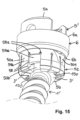
- Fig. 15 shows a modification of the coupling device of the embodiment described above with reference to Figs. 1 to 14 .
- similar or identical elements to these of Figs. 1 to 14 are denoted with the same reference numbers and a description thereof will not be repeated.
- the receiving part 5' of the coupling device of Fig. 15 differs from the receiving part 5 of the embodiment of Figs. 1 to 14 in the configuration of the structure that provides for an enlarged pivot angle. Specifically, instead of or in addition to the cutaway portions 151, at the modified receiving part 5' one of the wall sections 58b of the head receiving portion 52 is at least partially removed, as shown in Fig. 15 .
- the wall section 58b may be partially removed by breaking it away at the virtual connection line between the two end portions 58a of the slits 58 delimiting the flexible wall portion 58b so that only the interior wall portion 59e located above the opening 59a remains.
- the gap formed by removing a portion of the wall section 58b is provided at a circumferential position of the receiving part 5' that is different from the circumferential positions of the two recesses 150.
- the gap provides for a cutout portion configured to receive a portion of the shank of the bone anchor therein to thus provide for an enlarged pivot angle that the shank axis S of the bone anchor can form with the central axis C.
- the lowermost wall portion 50b and the radially thinner wall portion 50a of the adjacent wall sections 58b, as well as the head 3' of an inserted bone anchor are visible through the gap formed by removing a portion of the wall section 58b.
- the position of the enlarged pivot angle can be selected by breaking-off a suitable one of the wall sections 58b.
- Fig. 15 depicts the coupling device comprising the modified receiving part 5' with the second bone anchor 1' inserted.
- the modified receiving part 5' can also be connected to the first bone anchor 1.
- the locking member 6 is depicted in the insertion position where the second end 6b of the locking member 6 may be at an axial position above the end portions 58a of the slits 58 of the head receiving portion 52, and without a rod being inserted.
- the receiving part 5, 5' can be provided with both the cutaway portions 151 and the gap formed by partial removal of one of the wall sections 58b, which both provide for an enlarged pivot angle of an inserted shank with respect to the central axis C, or with only one of the cutaway portions 151 and partially removed wall section 58b.
- the receiving part may also comprise more than one cutaway portion 151 and/or more than one partially removed wall section 58b.
- the receiving part may also be provided without the cutaway portions 151 and partially removed wall section 58b, i.e., without any structure that provides for an enlarged pivot angle.
- an enlarged pivot angle does not necessarily imply a single enlarged pivot angle that the shank can assume with respect to the central axis C. Rather, the term “enlarged pivot angle” may also refer to a limited circumferential section of the receiving part where the shank can assume a larger pivot angle with respect to the central axis C than at other circumferential sections of the receiving part.
- the coupling device 10' comprises a receiving part 5" for receiving the head 3 of the bone anchor 1 and connecting the bone anchor 1 to a rod 100, and a locking member 6' for locking the head 3 in the receiving part 5".
- the receiving part 5" is a monolithic piece.
- the coupling device 10 further comprises a fixation member in the form of, for example, a fixation screw 7 for securing and fixing the rod 100 in the receiving part 5".
- the fixation member 7 and the bone anchor 1 may be similar to the fixation member 7 and the first bone anchor 1 of the system described above with reference to Figs. 1 to 15 .
- the receiving part 5" has a first or upper end 5a and a second or lower end 5b. Adjacent to the first end 5a, a rod receiving portion 51' is provided and adjacent to the second end 5b a head receiving portion 52' is provided.
- the rod receiving portion 51' is substantially cylindrical and comprises a passage or coaxial bore 53' that extends from the upper end 5a into the head receiving portion 52' and defines a longitudinal central axis C extending through the first end 5a and the second end 5b.
- the passage 53' comprises an internal thread 57' in at least a region thereof for receiving the fixation member 7.
- a substantially U-shaped recess 55' that forms a channel with a longitudinal axis L for receiving the rod 100 extends from the first end 5a of the receiving part 5" to almost the beginning of the head receiving portion 52'.
- a groove or otherwise weakened section 93 may be provided that allows to break-off the upper portions of the receiving part 5" formed by the U-shaped recess that serve as extended tabs.
- the engagement structure may comprise circumferentially extending ribs 94.
- the engagement structure may serve to facilitate assembling of the locking member 6' and/or prevent a rotational movement of the locking member 6' around the central axis C.
- the head receiving portion 52' that is formed adjacent the second end 5b of the receiving part 5" has a substantially cap-like shape with a hollow substantially spherical interior portion 101 that defines an accommodation space 54' for pivotably receiving the head 3 therein.
- a plurality of axially extending slits 102 that are open to the second end 5b and that may extend up to a distance from the second end 5b render the head receiving portion flexible so that when pressure is exerted onto the head receiving portion by the locking member 6', the head 3 can be clamped and locked.
- Two opposite recesses or slots 150' are formed at the bottom end 5b of the head receiving portion 52'.
- the recesses 150' are offset from each other by 180° and may be aligned with the longitudinal axis L defined by the U-shaped recess 55'.
- Each recess 150' is open towards the bottom end 5b and extends completely through a wall of the head receiving portion 52' from an inner surface of the wall that delimits the accommodation space 54' to an outer surface of the wall.
- An inner contour of the recesses 150' may be substantially rectangular.
- the width of the recesses 150' in the circumferential direction of the receiving part 5" may be smaller than the distance between two slits 102 and may be greater than the width of the slits 102.
- the recesses 150' define a restraining structure or a part of such a restraining structure that restrains a pivoting motion of an inserted head 3 of the bone anchor 1 to a single plane including the central axis C.
- the single plane is a plane defined by the central axis C and by the longitudinal axis L of the rod channel.
- the locking member 6' is formed as a closed ring designed to be positioned around and to encompass the head receiving portion 52'.
- An inner diameter of the locking member 6' is sized such that the locking member 6' fits around the receiving part 5" and is configured to slide along an outer surface of the head receiving portion 52'.
- the locking member 6' has an internal surface structure that allows to achieve in corporation with the head receiving portion 52' the locking of the head 3 in the head receiving portion 52' when the locking member 6' in its lowermost position or locking position, e.g., when a second or lower end 6b of the locking member 6' is close to or adjacent to the second end 5b of the receiving part 5".
- a pre-locking of an inserted head 3 may be provided when the locking member 6' is in a pre-locking position slightly above the lowermost position which allows still pivoting of the head 3 in the head receiving portion 52' but prevents removal of the head 3 from the head receiving portion 52'.
- the locking member 6' of Figs. 16 to 19 further comprises a number of upstanding flexible sections 63 that may serve for engagement with the receiving part 5" to preliminarily hold the locking member 6' in a pre-locking position (not shown in the figures). Also, two opposite projections 64 are provided at an upper side of the locking member 6' that serve for supporting the rod 100 at an upper surface 64a provided at the projections 64. In the embodiment shown, the locking member 6' also comprises two opposite upstanding arms 65. At an upper end of the arms 65 an engagement structure in the form of grooves 65a may be provided that is configured to be engaged by an instrument (not shown in the figures). An inner surface 65b of the arms 65 may be flat and configured to cooperate with the flat outer surface portions 95 of the rod receiving portion 51'.
- the cooperating flat outer surface portions 95 at the receiving part 5" and inner surfaces 65b at the locking member 6' may prevent inadvertent rotation of the locking member 6'.
- the locking member 6' may assume different axial positions with respect to the receiving part 5", such as an insertion position in which the head 3 of the bone anchor 1 can be inserted, the pre-locking position in which the head is still pivotable with respect to the receiving part 5" but is prevented from removal therefrom, and a locking position in which the head 3 is locked in its angular position.
- the locking member 6' and the receiving part 5" may be pre-assembled by mounting the locking member 6' to the receiving part 5 from the second end 5b of the receiving part 5. If a monoplanar bone anchoring device shall be assembled, the first bone anchor 1 is used. The head 3 of the first bone anchor 1 may be inserted into the accommodation space 54' of the receiving part 5" from the second end 5b thereof when the locking member 6' is in the insertion position. The wings 4 extend into the recesses 150'. Due to the slits 102, the head receiving portion 52' is flexible and snaps onto the head. Thereafter, the locking member 6' can be moved downward, for example with an instrument (not shown) whereby it compresses the head receiving portion 52'so that pressure is exerted on the head.
- the locking member 6' may be moved upwards, for example with an instrument, to loosen the locking of the head.
- the rod 100 may be already inserted into the substantially U-shaped recess 55' and the fixation member 7 is screwed into the passage 53' of the receiving part 5". Due to the extended tabs of the receiving part 5", the rod 100 is still movable so that the head can be locked independently from the rod.
- the fixation member 7 is tightened so that the rod 100 presses onto the surface 64a of the locking member 6' which further moved the locking member 6' into the locking position.
- the receiving part 5" of Figs. 16 to 19 may be provided with the cutaway portions 151 described above with reference to Figs. 1 to 15 to provide for an enlarged pivot angle of the bone anchor with respect to the central axis C.
- the coupling device 10' of the present embodiment may also be coupled to the second bone anchor 1' described above with reference to Figs. 1 to 15 .
- the resulting bone anchoring device is a polyaxial bone anchoring device in which the bone anchor can pivot in multiple planes.
- the first bone anchor 1 and the second bone anchor 1' may be interchangeably used together with one and the same coupling device 10'.
- at least one wall section delimited by two adjacent slits 102 of the head receiving portion 52' may be at least partially removed to provide for an enlarged pivot angle of the bone anchor with respect to the central axis C.
- the coupling device 10" of Figs. 16 to 19 differs from the coupling device 10' of Figs. 16 to 19 in that a pressure member 8 is provided in addition to the receiving part 5" and the locking member 6'.
- the pressure member 8 is configured to be arranged within the passage 53' of the receiving part 5" and configured to contact an inserted head 3 from above to additionally exert pressure onto an inserted head.
- the pressure member 8 is configured to exert pressure onto an inserted head only from above.
- the pressure member 8 extends from a first or upper end 8a to a second or lower end 8b and comprises a central passage 81 extending from the first end 8a to the second end 8b.
- a first portion 81a of the passage 81 adjacent the first end 81a is substantially cylindrical and provides for a substantially cylindrical inner surface of the pressure member 8.
- Adjacent to the second end 8b, a second portion 81b of the passage 81 has substantially spherically-shaped inner surface configured to contact the spherically-shaped outer surface portion of the head 3 from above.
- the pressure member 8 comprises a rod support surface 82 for supporting an inserted rod 100.
- the rod support surface 82 defines a channel axis K of the pressure member 8. Adjacent the rod support surface 82, opposing flat surfaces 82a may be formed at the first end 8a of the pressure member 8.
- two opposite recesses or slots 83 are formed, which are open to the second end 8b.
- the recesses 83 are offset from each other by 180° and are aligned with the axis K defined by the rod support surface 82.
- An inner contour of the recesses 83 may be substantially rectangular.
- An upper portion 83a that delimits the recesses 83 towards the first end 8a of the pressure member 8 may have a curved shape that corresponds to a shape of the upper end 4a of the wings 4 provided at the head 3 of the first bone anchor 1.
- the recesses 83 are configured to receive a portion of the wings 4 of the head 3 of the first bone anchor 1 therein. Specifically, the recesses 83 of the pressure member 8, together with the recesses 150' provided at the receiving part 5", define a restraining structure or a part of such a restraining structure, that restrains a pivoting motion of an inserted head of a bone anchor to a single plane including the central axis C.
- the pressure member 8 is mounted to the receiving part 5" in an orientation of the pressure member 8 such that the recesses 83 of the pressure member 8 are aligned with the recesses 150' of the receiving part 5" in the circumferential direction, and the axis K defined by the rod support surface 82 is aligned with the longitudinal axis L defined by the U-shaped recess 55' of the receiving part 5".
- the coupling device 10" can be assembled with the first bone anchor to a monoplanar bone anchoring device or with the second bone anchor to a polyaxial bone anchoring device.
- the final locking of the head is achieved by exterting pressure with the rod onto the pressure member 8 which in turn locks the head in the head receiving portion.
- the restraining structure in the receiving part 5, 5', 5" and/or the pressure member 8 can be at another position so that the single pivot plane can have an angle with respect to the channel axis. It may be also possible to provide more than one restraining structures at different locations such that several distinct pivot planes are provided one of which can be selected when inserting the first bone anchor.
- a further bone anchor of a third type may be provided that cooperates with the one or more than one restraining structures provided at the receiving part and/or the pressure member in such a way that the bone anchor assumes a predefined angular orientation with respect to the central axis C and is prevented from pivoting, i.e., the further bone anchor and the coupling device form a monoaxial bone anchoring device.
- the first bone anchor may have wings or any other restraining structure which have a distance from the free end of the head.
- the bone anchor is not limited to have a threaded shank. All types of bone anchors that are suitable for anchoring in bone or vertebrae may be used.
- the bone anchor can be a two part bone anchor that comprises a shank and a separate head connectable to the shank.
- different heads can be provided that can selectively be combined with a shank.
- one of the heads can be the head 3 comprising the restraining structure, such as the wings and another head can be a head 3' with a spherical outer surface as described without a restraining structure.
- a monoplanar head or a polyaxial head can selectively be combined with a shank.
- fixation member instead of the fixation member described above, other fixation devices may be used, such as, for example, a bayonet fixation device or a two part fixation device that allows the independent fixation of the rod and the head.
- fixation devices such as, for example, a bayonet fixation device or a two part fixation device that allows the independent fixation of the rod and the head.
Landscapes
- Health & Medical Sciences (AREA)
- Orthopedic Medicine & Surgery (AREA)
- Neurology (AREA)
- Life Sciences & Earth Sciences (AREA)
- Surgery (AREA)
- Heart & Thoracic Surgery (AREA)
- Engineering & Computer Science (AREA)
- Biomedical Technology (AREA)
- Nuclear Medicine, Radiotherapy & Molecular Imaging (AREA)
- Medical Informatics (AREA)
- Molecular Biology (AREA)
- Animal Behavior & Ethology (AREA)
- General Health & Medical Sciences (AREA)
- Public Health (AREA)
- Veterinary Medicine (AREA)
- Surgical Instruments (AREA)
Abstract
Description
- The present invention relates to a coupling device for coupling a rod to a bone anchor, to a bone anchoring device with such a coupling device and to a bone anchoring system comprising such a coupling device and at least two bone anchors.
- A coupling device is used in orthopedic surgery, in particular in spinal surgery, for coupling a rod to a head of a bone anchor that is anchored in bone or a vertebra. The head of the bone anchor may be pivotably received in a receiving part of the coupling device which also accommodates the rod, so that the receiving part can assume various angular positions with respect to the bone anchor. Thus, a suitable orientation of the bone anchor with respect to the rod can be achieved.
- In order to lock an inserted head in a specific angular position with respect to the receiving part,
EP 4 074 271 A1 - The bone anchoring device described in
EP 4 074 271 A1 - Various designs of monoplanar bone anchoring devices are known where the shank of a bone anchor can pivot in the receiving part only in a single plane. For example,
US 7,749,258 B2 describes a bone anchoring device in the form of a monoplanar bone anchoring device including a receiving part for receiving a rod, a pressure element and a bone anchoring element being movable relative to the receiving part in a limited angular range about the longitudinal axis of the receiving part, the angles lying in a single plane. The movement of the bone anchoring element relative to the receiving part is limited by a form fit connection comprising cooperating guiding surfaces at the head of the bone anchoring element and at the pressure element. - There is still a need to provide a coupling device having a simple structure with only few parts that may allow to implement at least a polyaxial and a monoplanar bone anchoring device.
- Thus, it is the object underlying the invention to provide a coupling device that can be used in a modular bone anchoring device that enables a selectable functionality in terms of a polyaxial and a monoplanar design. It is also an object to provide a bone anchoring system that includes such a coupling device and at least two bone anchors that provide a different functionality to the bone anchoring device.
- The object is solved by a coupling device according to
claim 1, by a bone anchoring device of claim 13 and by a bone anchoring system according claim 16. Further developments are given in the dependent claims. - According to an embodiment, a coupling device for selectively coupling a rod to a to a first bone anchor of a first type or to a second bone anchor of a second type is provided. The coupling device comprises a receiving part having a first end, an opposite second end and a central axis extending through the first end and the second end, the receiving part comprising a rod receiving portion for receiving the rod, and a head receiving portion, wherein the head receiving portion comprises an accommodation space for pivotably receiving a head of the first bone anchor or the second bone anchor such that a shank of the first or the second bone anchor can assume a plurality of angular positions relative to the central axis. The coupling device further comprises a locking member positionable at least partially around the head receiving portion and movable between at least a first position in which the head is pivotable and a second position in which the head is locked in the accommodation space; wherein the head receiving portion comprises a restraining structure by means of which the coupling device is configured to cooperate with the first bone anchor such that the first bone anchor is configured to pivot with respect to the central axis in a single plane, or with the second bone anchor such that the second bone anchor is configured to pivot with respect to the pivot axis in multiple planes when the locking member is in the first position.
- By selecting the first bone anchor and assembling it with the coupling device, the coupling device can be used as a monoplanar bone anchoring device. By selecting the second bone anchor and assembling it with the coupling device, the coupling device can be used as a polyaxial bone anchoring device. Since the same coupling device can be used with different bone anchors, the surgeon has a more flexible and versatile choice of implant combinations while the number of parts per set is reduced.
- Thus, with the coupling device a modular bone anchoring device can be implemented that can - at the choice of the user - be assembled from few interchangeable parts to allow use for different applications.
- The bone anchoring device with coupling device as described above is of the bottom loading type, i.e. the bone anchor can be inserted from the bottom end of the coupling device. This enables the assembly either prior to surgery or during surgery in situ when the bone anchor is already inserted into bone.
- In addition, as the coupling device may be more expensive and/or difficult to manufacture compared to the bone anchor, the manufacturing costs and/or the costs for stockholding can be decreased if the same coupling device can be used for more than one clinical application.
- For example, the coupling device or three-dimensional parts thereof may be manufactured using an additive manufacturing method, such as printing, for example laser sintering or laser or electron beam melting. With such a method complex shapes can be easily manufactured on the basis of CAD data of the object to be manufactured.
- According to a further embodiment, a receiving part is provided that comprises a first end, an opposite second end and a central axis extending through the first end and the second end. The receiving part comprises a rod receiving portion for receiving the rod and a head receiving portion that defines an accommodation space for receiving a head of a bone anchor. The head receiving portion further comprises a number of slits that are open to the second end of the receiving part, the slits forming a number of wall sections of the head receiving portion. The slits and wall sections preferably render the head receiving portion flexible, in particular compressible and/or expandable. Further, at least one cutout portion is provided at the head receiving portion by removing, preferably cutting away, at least a portion of one of the wall sections.Preferably, the cutout portion is configured to receive at least a portion of a shank of the bone anchor therein to provide for an enlarged pivot angle of the bone anchor in a predefined direction with respect to the central axis or at least a limited angular range in the circumferential direction of the receiving part.
- As used in the present specification and the appended claims, the term "rod" shall be understood as including any elongate member, regardless of the cross-sectional shape. Specifically, a spinal stabilization rod as used herein may have substantially circular, oval, or angular cross-section. Such a cross-section may vary along the length of the rod.
- Fig. 1
- shows a perspective exploded view of a system according to an embodiment including a coupling device with two bone anchors that can be used in an interchangeable manner.
- Fig. 2
- shows a perspective view of an embodiment of a bone anchoring device assembled from parts of the system of
Fig. 1 in the assembled state. - Fig. 3
- shows a cross-sectional view of the bone anchoring device of
Fig. 2 in a plane including a central axis of the receiving part and a longitudinal axis of the rod. - Fig. 4
- shows a perspective view from a bottom of the receiving part of the coupling device of
Figs. 1 to 3 . - Fig. 5
- shows a perspective view from a top of the receiving part of
Figs. 1 to 3 . - Fig. 6
- shows a top view of the receiving part of
Figs. 4 and 5 . - Fig. 7
- shows a cross-sectional view of the receiving part of
Figs. 4 to 6 , the cross-section taken along line A-A inFig. 6 . - Fig. 8
- shows a cross-sectional view of the receiving part of
Figs. 4 to 7 , the cross-section taken perpendicular to the line A-A inFig. 6 . - Fig. 9
- shows a perspective view from a top of the locking member of the coupling device of
Figs. 1 to 3 . - Fig. 10
- shows a cross-sectional view of the locking member of
Fig. 9 , the cross-section taken perpendicular to a central axis of the locking member. - Fig. 11
- shows a perspective view of an embodiment of a first bone anchor of the system of
Fig. 1 . - Fig. 12
- shows a perspective view of a portion of the first bone anchor of
Fig. 11 . - Fig. 13
- shows a side view of a portion of the first bone anchor of
Figs. 11 and 12 . - Fig. 14
- shows a top view of the first bone anchor of
Figs. 11 to 13 . - Fig. 15
- shows a perspective view of a modified embodiment of the bone anchoring device of
Figs. 1 to 14 in the assembled state. - Fig. 16
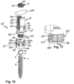
- shows a perspective exploded view of a bone anchoring device comprising a coupling device according to a further embodiment and a bone anchor.
- Fig. 17
- shows a perspective view of an enlarged portion of a lower part of the receiving part of the bone anchoring device of
Fig. 16 . - Fig. 18
- shows a perspective view of the bone anchoring device of
Figs. 17 and18 in an assembled state from below. - Fig. 19
- shows a cross-sectional view of the bone anchoring device of
Figs. 16 to 18 in a plane including a central axis of the receiving part and a longitudinal axis of the rod. - Fig. 20
- shows a perspective exploded view of a modified embodiment of the bone anchoring device of
Figs. 16 to 19 . - Fig. 21
- shows a perspective view of an enlarged portion of a lower part of the receiving part of the bone anchoring device of
Fig. 20 . - Fig. 22
- shows a cross-sectional view of the assembled bone anchoring device of
Figs. 20 and 21 in a plane including a central axis of the receiving part and a longitudinal axis of the rod. - Fig. 23
- shows a perspective view from a top of a pressure member of the bone anchoring device of
Figs. 20 to 22 . - Fig. 24
- shows a perspective view from a bottom of the pressure member of
Figs. 20 to 22 . - Fig. 25
- shows a top view of the pressure member of
Figs. 23 and 24 . - Fig. 26
- shows a cross-sectional view of the pressure member of
Figs. 23 to 25 , the cross-section taken along line B-B inFig. 25 . - Referring to
Fig. 1 , a system of a coupling device and two bone anchors according to an embodiment includes afirst bone anchor 1 of a first type and a second bone anchor 1' of a second type and acoupling device 10 that is connectable to thefirst bone anchor 1 or the second bone anchor 1'. When thecoupling device 10 is assembled with thefirst bone anchor 1, the resulting bone anchoring device is an monoplanar bone anchoring device in which thefirst bone anchor 1 can pivot only in a single plane. When the coupling device is assembled with the second bone anchor 1', the resulting bone anchoring device is a polyaxial bone anchoring device in which the bone anchor 1' can pivot in multiple planes. Thus, thefirst bone anchor 1 and the second bone anchor 1' may be interchangeably used together with one and thesame coupling device 10. - The
coupling device 10 includes a receivingpart 5 and a lockingmember 6. The receivingpart 5 comprises arod receiving portion 51 for receiving arod 100 and ahead receiving portion 52 for accommodating ahead 3 of thefirst bone anchor 1 or a head 3' of the second bone anchor 1'. Preferably, the receiving part is a monolithic piece. The lockingmember 6 is positionable around thehead receiving portion 52 of the receivingpart 5 and is movable between at least a first position and a second position along an outer surface of the receivingpart 5. The lockingmember 6 is configured to exert pressure onto thehead receiving portion 52 and onto an inserted head at least when the lockingmember 6 is in the second position to lock the head in the receivingpart 5 in a particular angular position of theshank 2. Preferably, the lockingmember 6 is a closed ring. - The
coupling device 10 further comprises a fixation member in the form of, for example, afixation screw 7 for securing and fixing therod 100 in the receivingpart 5. Thefixation member 7 comprises an engagement structure at an outer surface thereof, for example anexternal thread 71, and atool engagement recess 72. Thefixation member 7 may be, for example, a set screw that can be screwed into the receivingpart 5.Figs. 2 and3 show thefirst bone anchor 1 assembled with thecoupling device 10 and therod 100 inserted and fixed by thefixation member 7. - As depicted in greater detail in
Figs. 4 to 8 , the receivingpart 5 may be substantially cylindrical and comprises a first end ortop end 5a, a second end orbottom end 5b, and a passage or bore 53 extending from thefirst end 5a towards thesecond end 5b and defining a longitudinal central axis C extending through thefirst end 5a and thesecond end 5b. Therod receiving portion 51 is formed adjacent thefirst end 5a and thehead receiving portion 52 is formed at thesecond end 5b. - The
passage 53 extends from thefirst end 5a to a distance therefrom and merges into anintermediate portion 53a that has a reduced diameter. Theintermediate portion 53a may be, for example, cylindrical. Adjacent to theintermediate portion 53a, anaccommodation space 54 is formed that is shaped and sized to accommodate thehead 3 of thefirst bone anchor 1 or the head 3' of the second bone anchor 1' therein. Theaccommodation space 54 has anopening 54a at thesecond end 5b of the receivingpart 5. - A substantially
U-shaped recess 55 extends from thefirst end 5a of the receivingpart 5 to a distance therefrom. The substantiallyU-shaped recess 55 divides the receivingpart 5 into twolegs 56 and forms a channel with a longitudinal axis L for receiving therod 100. A bottom 55a of the channel may have a substantially V-shaped upper contour which provides a rod support surface for an insertedrod 100. By means of this, rods with different diameters may be inserted into the channel and can be supported on the rod support surface. Aninternal thread 57, for example a flat thread or a square thread, is formed in thepassage 53 on thelegs 56 adjacent to thefirst end 5a for cooperating with theexternal thread 71 of thefixation member 7. By means of theU-shaped recess 55, the upper portion of the receiving part defines therod receiving portion 51. - A lower portion of the receiving
part 5, approximately from theintermediate portion 53a of thepassage 53 to thesecond end 5b, which comprises theaccommodation space 54, defines thehead receiving portion 52 of the receivingpart 5. Theaccommodation space 54 has a substantially spherical inner contour that matches an outer contour of thehead 3 of thefirst bone anchor 1 and the head 3' of the second bone anchor 1'. The axial extension of theaccommodation space 54 in the direction of the central axis C is such that it covers a region with a greatest outer diameter E of thehead 3 or 3' when the head is inserted into theaccommodation space 54. More specifically, the size of theaccommodation space 54 may be such that thehead 3 of thefirst bone anchor 1 or the head 3' of the second bone anchor 1' can be held therein by friction. A small chamferedportion 54b may be provided for facilitation the insertion of the head. As can be seen in particular inFigs. 7 and 8 , theaccommodation space 54 is divided in anupper portion 54c configured to cover thehead 3, 3' from the top and a lower portion including aseat 54d for thehead 3, 3' in which the head can pivot. - A wall of the receiving
part 5 around theaccommodation space 54 is expandable and compressible in a radial direction with respect to the central axis C. This is achieved by a plurality of axially extendingslits 58 that are open to thesecond end 5b and that may extend up to a distance from thesecond end 5b, preferably up to theintermediate portion 53a of thepassage 53. Anend portion 58a of theslits 58 is enlarged, for example with a diamond-shaped contour, a circular contour or a triangular contour or any other suitable shape. Theslits 58 form a number offlexible wall sections 58b of thehead receiving portion 52. The size and number of theslits 58 may be selected such as to obtain a desired flexibility of thehead receiving portion 52. - A
cavity 59 is formed in the wall of thehead receiving portion 52, thecavity 59 extending circumferentially around theaccommodation space 54. Thecavity 59 may extend in the axial direction of the central axis C from a position below a region accommodating the greatest diameter E of the head up to theend portions 58a of theslits 58. Thus, thecavity 59 encircles an inserted head circumferentially and extends along a substantial region in the direction of the central axis C along thehead 3, 3'. Moreover, thecavity 59 is in communication with theaccommodation space 54 through anopening 59a which has a smaller width in the direction of the central axis C than a radially outer portion of thecavity 59. More specifically, theopening 59a has the shape of an annular slit as can be seen in particular inFigs. 4, 7 and 8 . An outwardly directedwall portion 59b defining thecavity 59 may be slightly convex and may be formed at a radial position away from the central axis C so that a radiallyoutermost wall portion 50a of thehead receiving portion 52 is thinner than alowermost wall portion 50b below thecavity 59 at or adjacent to thesecond end 5b. Also, theend portions 58a of theslits 58 are in communication with thecavity 59. A virtual connection line between twoadjacent end portions 58a of theslits 58 may thus, together with the radiallythinner wall portion 50a of thehead receiving portion 52, define a predetermined breaking point or breaking line for removing a portion of therespective wall section 58b, as explained in more detail below. - An
upper wall portion 59c of the wall defining thecavity 59 may be inclined and tapered towards thesecond end 5b up to theopening 59a. Alower wall portion 59d of the wall defining thecavity 59 may be substantially flat in a direction substantially perpendicular to the central axis C and may be rising in a curved or inclined manner towards theopening 59a. It shall be noted that the detailed shape of the cavity is not limited to the embodiment shown but may vary. - By the
opening 59a of thecavity 59, theaccommodation space 54 is divided into theupper portion 54c and theseat 54d which can be pressed against thehead 3, 3' by the lockingmember 6. Theupper portion 54c of the accommodation space is at least partially delimited by aninterior wall portion 59e located above theopening 59a. - The
wall portion 50a is thin compared to thewall portion 50b when seen in the radial direction. Due to thecavity 59, theflexible wall sections 58b of thewall portion 50b can be easily spread although they are relatively thick at thesecond end 5b of the receivingpart 5. When thehead receiving portion 52 is compressed by the lockingmember 6, as described below, thelowermost wall portion 50b is configured to exert pressure onto thehead 3, 3' from an axial position at or close to the region with the greatest diameter E of the head and from below this region as depicted inFig. 3 . As thewall sections 58b of thewall portion 50b are thicker there, a sufficiently strong clamping force can be achieved. Also, the strength against loosening may be enhanced by this design. In other words, the wall sections provide astable seat 54d for thehead 3, 3' in which the head can be safely clamped. - The outer surface of the wall of the
head receiving portion 52 widens in a taperedportion 50c close to thesecond end 5b towards thesecond end 5b. Thereby, the compression force increases when the lockingmember 6 is moved along thehead receiving portion 52 in a direction to thesecond end 5b. Between the taperedportion 50c and thesecond end 5b, anouter surface portion 105 may be convexly rounded. - As best shown in
Figs. 4 and 6 to 8 , two opposite recesses orslots 150 are formed at thebottom end 5b of thehead receiving portion 52. Therecesses 150 are offset from each other by 180° and are aligned with the longitudinal axis L defined by the channel when seen in a top view as shown inFig. 6 . In greater detail, therecesses 150 extend from thebottom end 5b through theseat 54d and theupper portion 54c of theaccommodation space 54 up to theintermediate portion 53a of thepassage 53. An inner contour of therecesses 150 may be substantially rectangular. Therecesses 150 may be provided at circumferential positions of the receivingpart 5 whereslits 58 are formed, i.e. they may include aslit 58 as shown inFig. 4 . In the radial direction, therecesses 150 extend from an inner surface 154a of the wall of the head receiving portion 52towards an outer surface 154b of the wall and end at a distance from the outer surface 154b, as shown inFig. 4 . Hence, therecesses 150 are open towards theaccommodation space 54 and do not extend entirely through the wall of the receivingpart 5 in the radial direction. Moreover, therecesses 150 do not substantially extend into thecavity 59. - By means of the
recesses 150, it is possible to insert thehead 3 of thefirst bone anchor 1 from thebottom end 5b, as explained further below. Specifically, therecesses 150 define a restraining structure or a part of such a restraining structure, that restrains a pivoting motion of an insertedhead 3 of thebone anchor 1 of the first type to a single plane including the central axis C. - The receiving
part 5 further comprisescutaway portions 151 formed adjacent to both sides of one of therecesses 150 which are configured to receive a portion of theshank 2 of the bone anchor therein.Thecutaway portions 151 are formed in aninner edge 152 around thelower opening 54a of the receivingpart 5. An axial and radial extension of thecutaway portions 151 is smaller than an axial and radial extension of therecess 150. Thecutaway portions 151 may have a substantially triangular shape and form chamfered surfaces that gradually merge from theedge 152 into therecess 150. Thus, thecutaway portions 151 provide for an enlarged pivot angle that the shank axis S of thefirst bone anchor 1 or of the second bone anchor 1' can form with the central axis C when pivoting to the position of thecutaway portions 151. It shall be noted that thecutaway portions 151 may be formed at both sides of each of therecesses 150. - At the center of each
leg 56 in a circumferential direction, a throughhole 500 or another engagement structure may be provided for engagement with an instrument. Moreover,inclined cutaway portions 501 may be formed at either end of the channel for the rod close to the bottom 55a of the substantially U-shaped recess. Additionalchamfered portions 502 may extend from thecutaway portions 501 to some extent towards the edges of each of thelegs 56 on either side of the channel. Thecutaway portions 501 and chamferedportions 502 may facilitate the mounting of the lockingmember 6 from thefirst end 5a of the receivingpart 5 and/or reduce the size of the receivingpart 5. - Referring additionally to
Figs. 9 and 10 , the lockingmember 6 will be described in greater detail. The lockingmember 6 is formed as a closed ring with a first orupper end 6a and a second orlower end 6b. Aninner surface 61 of the lockingmember 6 is substantially cylindrical with an inner diameter sized such that the lockingmember 6 fits around the receivingpart 5 and is configured to slide along the outer surface of the receivingpart 5. Adjacent to thesecond end 6b, the lockingmember 6 may comprise a taperedinner surface portion 62 that tapers towards thefirst end 6a and is configured to cooperate with the taperedouter surface portion 50c of the receivingpart 5. The angle of the tapered portions of the lockingmember 6 and the receivingpart 5 preferably correspond to each other. Preferably, the angle is selected such that a self-locking occurs when the surfaces engage each other. Thus, once the lockingmember 6 is mounted and the tapered surfaces engage each other, the lockingmember 6 is prevented from being inadvertently moved upward and the locking is loosened. However, it may be possible to disengage the cooperating surfaces, for example using an instrument. - The outer surface of the locking
member 6 may be cylindrical and may comprise an engagement structure for engagement with an instrument (not shown in the figures). Adjacent to thesecond end 6b the outer surface may be tapered towards thesecond end 6b. However, the shape is not limited to such a design. The axial length of the lockingmember 6 between thefirst end 6a and thesecond end 6b may be at least the axial extension of thecavity 59 of the receivingpart 5, preferably greater than the axial length of thecavity 59. Thus, the lockingmember 6 is configured to exert a radial compression force onto a major part of thehead receiving portion 52 of the receiving part. The lockingmember 6 can be mounted to the receivingpart 5 from the second end of the receivingpart 5 or from thefirst end 5a thereof. - Referring further to
Figs. 11 to 14 , thefirst bone anchor 1 will be described in greater detail. Thebone anchor 1 comprises ashank 2 with a shank axis S, wherein the shank is preferably fully or partially threaded, and ahead 3 with a free end 3a. Between thehead 3 and theshank 2 there may be aneck portion 2a. Thehead 3 has a spherical outer surface portion that includes the region with the greatest diameter E of the sphere. Preferably, the spherical outer surface portion is in the axial direction substantially symmetrical with respect to a plane including the plane of the greatest outer diameter E. In addition, thehead 3 comprises twoopposite wings 4 that project from the spherical surface of the head away from the shank axis S. Eachwing 4 extends parallel to the shank axis S along the spherical surface of thehead 3. The wings may extend from the free end 3a of thehead 3 up to theneck 2a or may be provided at a distance from the free and 3a of the head and/or at a distance to theneck 2a. - The
wings 4 are offset by 180° along the circumferential direction of thehead 3 and are symmetrical with respect to a middle plane including the shank axis S. Eachwing 4 has a shape of a spherical shell segment. Anupper end 4a of thewings 4 may be flat and slightly inclined towards theshank 2. However, theupper end 4a may also be curved. A width of thewings 4 is such that when thehead 3 is received in thehead receiving portion 52 of the receivingpart 5, thewings 4 can extend into therecesses 150 and pivot therein. Thus, thewings 4 form a restraining structure or a part of a restraining structure that cooperates with the corresponding restraining structure in the form of therecesses 150 provided at the receivingpart 5 to limit or restrain the pivoting motion of thehead 3 in thehead accommodation space 54 to a single plane. It shall be noted that the width of thewings 4 is such that when thehead 3 passes through thelower opening 54a of the receivingpart 5 during insertion, thewings 4 pass through therecesses 150 at thebottom end 5b of the receivingpart 5. - Moreover, at the free end 3a of the
bone anchor 1, atool engagement recess 31 is formed that may have a polygon or any other engagement structure such as, for example a torx-shaped or star-shaped or other axial groove-shaped structure suitable to screw thebone anchor 1 into bone. - Referring to
Fig. 1 , the second bone anchor 1' will be described in greater detail. Parts and portions that are identical to thefirst bone anchor 1 are marked with the same reference numerals and the description thereof is not repeated. The second bone anchor 1' differs from thefirst bone anchor 1 in that the head 3' of the second bone anchor lacks thewings 4. Hence, the outer surface of the head 3' is uniformly spherically-shaped between theneck portion 2a and the free end surface 3a. As a result, when the second bone anchor 1' is inserted into thecoupling device 10, the head 3' can freely pivot in theaccommodation space 54 of the receivingpart 5 without being restrained. This means the second bone anchor 1' can pivot relative to the central axis C in multiple planes, even in an unlimited number of planes. - Parts and portions of the polyaxial bone anchoring device may be made of any material, preferably, however, of a bio-compatible material, such as titanium or stainless steel or any other bio-compatible metal or metal alloy, or plastic material. As bio-compatible alloy, a NiTi-alloy, for example Nitinol, may be used. Other materials can be Magnesium or Magnesium alloys, bio-compatible plastic materials for use may be for example, Polyether ether ketone (PEEK) or Poly-L-lactide acid (PLLA). The parts can be made of the same or of different materials from one another.
- A preferred method of manufacturing the receiving part and optionally also the locking member and/or the bone anchoring element is an additive manufacturing method, more preferably an additive layer manufacturing method, such as three-dimensional printing. More particularly, preferred methods are laser sintering or laser melting or electron beam melting. In such a method, subsequent layers of a powder material, such as a metal powder, are solidified with an energy beam, particularly a laser or an electron beam, at positions corresponding to the cross-section of the part in the respective layer.
- In use, the
coupling device 10 may be pre-assembled. For assembly, the lockingmember 6 may be mounted to the receivingpart 5 from thefirst end 5a or from thesecond end 5b. In an insertion position of the lockingmember 6, where thesecond end 6b of the lockingmember 6 may be at an axial position above theend portions 58a of theslits 58 of the head receiving portion 52 (seeFig. 15 ), theaccommodation space 54 of the receivingpart 5 can expand in the radial direction when thehead 3, 3' of the bone anchor is inserted. Thepre-assembled coupling device 10 can be connected to abone anchor 1, 1' either prior to inserting the bone anchor into bone or after the bone anchor has been inserted into bone. In both cases, the head of the bone anchor is inserted into the receivingpart 5 through thelower opening 54a and further moved into theaccommodation space 54 of the receivingpart 5. Due to theslits 58 of thehead receiving portion 52 the receivingpart 5 snaps onto the head. Thereafter, the lockingmember 6 is moved downward in the direction of the central axis C to compress thehead receiving portion 52 by means of the cooperating taperedinner surface portion 62 of the lockingmember 6 and the taperedouter surface portion 50c of the receivingpart 5. In this position, theinner surface 61 of the lockingmember 6 is positioned around thehead receiving portion 52 and fully encloses thehead receiving portion 52. The compression of thehead receiving portion 52 may lock the angular position of the bone anchor with respect to the receiving part. If the lockingmember 6 is mounted to the receivingpart 5 from the first end, the receivingpart 5 may first be connected to the bone anchor and then the lockingmember 6 may be mounted. - The system of the coupling device and the at least two bone anchors comprising the
first bone anchor 1 and the second bone anchor 1' allows to selectively combine thecoupling device 10 with either thefirst bone anchor 1 or the second bone anchor 1'. Hence, using thesame coupling device 10 either a monoplanar bone anchoring device or a polyaxial bone anchoring device can be generated. Specifically, when the second bone anchor 1' is inserted into the coupling device, the second bone anchor 1' is configured to pivot around the central axis C in multiple planes. The restraining structure in the form of therecesses 150 provided at the receivingpart 5 does not limit, i.e. has no influence on the pivoting motion of the second bone anchor 1'. At the position where thecutaway portions 151 are formed, the second bone anchor 1' is configured to assume an enlarged pivot angle of its shank axis S with respect to the central axis C. For example, without thecutaway portions 151, a maximum pivot angle of the shank axis S with the central axis C may be approximately 32°, and with thecutaway portions 151 an enlarged pivot angle may be approximately 42°. After insertion of therod 100, thefixation member 7 is screwed between thelegs 57 of the receiving part to secure therod 100 in the receiving part. - When the
first bone anchor 1 is inserted into thecoupling device 10, thehead 3 is oriented with respect to the coupling device in such a manner that thewings 4 can engage therecesses 150 of the receiving part. By means of this, the pivoting motion of thefirst bone anchor 1 is restricted to a single plane. In the embodiment, due to the position of the restraining structure, the single plane is a plane defined by the central axis C and by the longitudinal axis L of the rod channel. Thecutaway portions 151 provide for an enlarged pivot angle of the second bone anchor 1' with respect to the central axis C. After insertion of therod 100 thefixation member 7 is screwed between thelegs 57 of the receiving part to secure therod 100 in the receiving part. -
Fig. 3 shows the locking position of the lockingmember 6, where thefixation member 7 presses therod 100 onto thefirst end 6a of the lockingmember 6 to keep the lockingmember 6 in its lowermost position. In the locking position, thesecond end 6b of the lockingmember 6 is close to thesecond end 5b of the receivingpart 5 and fully encloses thehead receiving portion 52. - A pre-locking of an inserted
head 3, 3' may be provided when the lockingmember 6 is in a pre-locking position slightly above the lowermost position which allows still pivoting of thehead 3, 3' in thehead receiving portion 52 but prevents removal of thehead 3, 3' from thehead receiving portion 52. -
Fig. 15 shows a modification of the coupling device of the embodiment described above with reference toFigs. 1 to 14 . InFig. 15 , similar or identical elements to these ofFigs. 1 to 14 are denoted with the same reference numbers and a description thereof will not be repeated. - The receiving part 5' of the coupling device of
Fig. 15 differs from the receivingpart 5 of the embodiment ofFigs. 1 to 14 in the configuration of the structure that provides for an enlarged pivot angle. Specifically, instead of or in addition to thecutaway portions 151, at the modified receiving part 5' one of thewall sections 58b of thehead receiving portion 52 is at least partially removed, as shown inFig. 15 . Thewall section 58b may be partially removed by breaking it away at the virtual connection line between the twoend portions 58a of theslits 58 delimiting theflexible wall portion 58b so that only theinterior wall portion 59e located above theopening 59a remains. The gap formed by removing a portion of thewall section 58b is provided at a circumferential position of the receiving part 5' that is different from the circumferential positions of the tworecesses 150. The gap provides for a cutout portion configured to receive a portion of the shank of the bone anchor therein to thus provide for an enlarged pivot angle that the shank axis S of the bone anchor can form with the central axis C. Thelowermost wall portion 50b and the radiallythinner wall portion 50a of theadjacent wall sections 58b, as well as the head 3' of an inserted bone anchor are visible through the gap formed by removing a portion of thewall section 58b. It shall be noted that the position of the enlarged pivot angle can be selected by breaking-off a suitable one of thewall sections 58b. -
Fig. 15 depicts the coupling device comprising the modified receiving part 5' with the second bone anchor 1' inserted. However, the modified receiving part 5' can also be connected to thefirst bone anchor 1. Moreover, inFig. 15 , the lockingmember 6 is depicted in the insertion position where thesecond end 6b of the lockingmember 6 may be at an axial position above theend portions 58a of theslits 58 of thehead receiving portion 52, and without a rod being inserted. - The receiving
part 5, 5' can be provided with both thecutaway portions 151 and the gap formed by partial removal of one of thewall sections 58b, which both provide for an enlarged pivot angle of an inserted shank with respect to the central axis C, or with only one of thecutaway portions 151 and partially removedwall section 58b. The receiving part may also comprise more than onecutaway portion 151 and/or more than one partially removedwall section 58b. However, the receiving part may also be provided without thecutaway portions 151 and partially removedwall section 58b, i.e., without any structure that provides for an enlarged pivot angle. It should be noted here that "an enlarged pivot angle" does not necessarily imply a single enlarged pivot angle that the shank can assume with respect to the central axis C. Rather, the term "enlarged pivot angle" may also refer to a limited circumferential section of the receiving part where the shank can assume a larger pivot angle with respect to the central axis C than at other circumferential sections of the receiving part. - Next, an embodiment of a polyaxial bone anchoring device comprising a coupling device 10' of a further embodiment and the
first bone anchor 1 will be described with reference toFigs. 16 to 19 . The coupling device 10' comprises a receivingpart 5" for receiving thehead 3 of thebone anchor 1 and connecting thebone anchor 1 to arod 100, and a locking member 6' for locking thehead 3 in the receivingpart 5". Preferably, the receivingpart 5" is a monolithic piece. Thecoupling device 10 further comprises a fixation member in the form of, for example, afixation screw 7 for securing and fixing therod 100 in the receivingpart 5". Thefixation member 7 and thebone anchor 1 may be similar to thefixation member 7 and thefirst bone anchor 1 of the system described above with reference toFigs. 1 to 15 . - The receiving
part 5" has a first orupper end 5a and a second orlower end 5b. Adjacent to thefirst end 5a, a rod receiving portion 51' is provided and adjacent to thesecond end 5b a head receiving portion 52' is provided. The rod receiving portion 51' is substantially cylindrical and comprises a passage or coaxial bore 53' that extends from theupper end 5a into the head receiving portion 52' and defines a longitudinal central axis C extending through thefirst end 5a and thesecond end 5b. The passage 53' comprises an internal thread 57' in at least a region thereof for receiving thefixation member 7. A substantially U-shaped recess 55' that forms a channel with a longitudinal axis L for receiving therod 100 extends from thefirst end 5a of the receivingpart 5" to almost the beginning of the head receiving portion 52'. At a distance from theupper end 5a a groove or otherwise weakenedsection 93 may be provided that allows to break-off the upper portions of the receivingpart 5" formed by the U-shaped recess that serve as extended tabs. By means of the extended tabs it is possible to manipulate the polyaxial bone anchoring device with an insertedrod 100 that is at a higher position compared to the final position so that, for example, a vertebra can be pulled against the rod. - At an outer surface of the rod receiving portion 51' an engagement structure for engagement with an instrument (not shown the figures) may be provided. The engagement structure may comprise circumferentially extending
ribs 94. At a position below theribs 94 flatouter surface portions 95 are provided at the rod receiving portion 51' that may serve to facilitate assembling of the locking member 6' and/or prevent a rotational movement of the locking member 6' around the central axis C. - As shown in more detail in
Fig. 17 , the head receiving portion 52' that is formed adjacent thesecond end 5b of the receivingpart 5" has a substantially cap-like shape with a hollow substantially sphericalinterior portion 101 that defines an accommodation space 54' for pivotably receiving thehead 3 therein. A plurality of axially extendingslits 102 that are open to thesecond end 5b and that may extend up to a distance from thesecond end 5b render the head receiving portion flexible so that when pressure is exerted onto the head receiving portion by the locking member 6', thehead 3 can be clamped and locked. - Two opposite recesses or slots 150' are formed at the
bottom end 5b of the head receiving portion 52'. The recesses 150' are offset from each other by 180° and may be aligned with the longitudinal axis L defined by the U-shaped recess 55'. Each recess 150' is open towards thebottom end 5b and extends completely through a wall of the head receiving portion 52' from an inner surface of the wall that delimits the accommodation space 54' to an outer surface of the wall. In the figures, only one of the recesses 150' can be seen, whereas the other one is hidden from view by the head receiving portion 52'. An inner contour of the recesses 150' may be substantially rectangular. The width of the recesses 150' in the circumferential direction of the receivingpart 5" may be smaller than the distance between twoslits 102 and may be greater than the width of theslits 102. - By means of the recesses 150', it is possible to insert the
head 3 of thefirst bone anchor 1 of the first type from thebottom end 5b with thehead 3 oriented in such a manner that thewings 4 can engage the recesses 150' of the receivingpart 5". The recesses 150' define a restraining structure or a part of such a restraining structure that restrains a pivoting motion of an insertedhead 3 of thebone anchor 1 to a single plane including the central axis C. In the present embodiment, due to the position of the restraining structure 150', the single plane is a plane defined by the central axis C and by the longitudinal axis L of the rod channel. - The locking member 6' is formed as a closed ring designed to be positioned around and to encompass the head receiving portion 52'. An inner diameter of the locking member 6' is sized such that the locking member 6' fits around the receiving
part 5" and is configured to slide along an outer surface of the head receiving portion 52'. The locking member 6' has an internal surface structure that allows to achieve in corporation with the head receiving portion 52' the locking of thehead 3 in the head receiving portion 52' when the locking member 6' in its lowermost position or locking position, e.g., when a second orlower end 6b of the locking member 6' is close to or adjacent to thesecond end 5b of the receivingpart 5". A pre-locking of an insertedhead 3 may be provided when the locking member 6' is in a pre-locking position slightly above the lowermost position which allows still pivoting of thehead 3 in the head receiving portion 52' but prevents removal of thehead 3 from the head receiving portion 52'. - The locking member 6' of
Figs. 16 to 19 further comprises a number of upstandingflexible sections 63 that may serve for engagement with the receivingpart 5" to preliminarily hold the locking member 6' in a pre-locking position (not shown in the figures). Also, twoopposite projections 64 are provided at an upper side of the locking member 6' that serve for supporting therod 100 at anupper surface 64a provided at theprojections 64. In the embodiment shown, the locking member 6' also comprises two oppositeupstanding arms 65. At an upper end of thearms 65 an engagement structure in the form ofgrooves 65a may be provided that is configured to be engaged by an instrument (not shown in the figures). Aninner surface 65b of thearms 65 may be flat and configured to cooperate with the flatouter surface portions 95 of the rod receiving portion 51'. The cooperating flatouter surface portions 95 at the receivingpart 5" andinner surfaces 65b at the locking member 6' may prevent inadvertent rotation of the locking member 6'. In the mounted state, the locking member 6' may assume different axial positions with respect to the receivingpart 5", such as an insertion position in which thehead 3 of thebone anchor 1 can be inserted, the pre-locking position in which the head is still pivotable with respect to the receivingpart 5" but is prevented from removal therefrom, and a locking position in which thehead 3 is locked in its angular position. - The locking member 6' and the receiving
part 5" may be pre-assembled by mounting the locking member 6' to the receivingpart 5 from thesecond end 5b of the receivingpart 5. If a monoplanar bone anchoring device shall be assembled, thefirst bone anchor 1 is used. Thehead 3 of thefirst bone anchor 1 may be inserted into the accommodation space 54' of the receivingpart 5" from thesecond end 5b thereof when the locking member 6' is in the insertion position. Thewings 4 extend into the recesses 150'. Due to theslits 102, the head receiving portion 52' is flexible and snaps onto the head. Thereafter, the locking member 6' can be moved downward, for example with an instrument (not shown) whereby it compresses the head receiving portion 52'so that pressure is exerted on the head. If necessary, the locking member 6' may be moved upwards, for example with an instrument, to loosen the locking of the head. Therod 100 may be already inserted into the substantially U-shaped recess 55' and thefixation member 7 is screwed into the passage 53' of the receivingpart 5". Due to the extended tabs of the receivingpart 5", therod 100 is still movable so that the head can be locked independently from the rod. For final locking, thefixation member 7 is tightened so that therod 100 presses onto thesurface 64a of the locking member 6' which further moved the locking member 6' into the locking position. - In a modification of the receiving
part 5" ofFigs. 16 to 19 , the receivingpart 5" may be provided with thecutaway portions 151 described above with reference toFigs. 1 to 15 to provide for an enlarged pivot angle of the bone anchor with respect to the central axis C. - The coupling device 10' of the present embodiment may also be coupled to the second bone anchor 1' described above with reference to
Figs. 1 to 15 . When the coupling device 10' is assembled with the second bone anchor 1', the resulting bone anchoring device is a polyaxial bone anchoring device in which the bone anchor can pivot in multiple planes. Thus, thefirst bone anchor 1 and the second bone anchor 1' may be interchangeably used together with one and the same coupling device 10'. Alternatively or in addition, at least one wall section delimited by twoadjacent slits 102 of the head receiving portion 52' may be at least partially removed to provide for an enlarged pivot angle of the bone anchor with respect to the central axis C. - Next, a further modification of the coupling device will be described with respect to
Figs. 20 to 26 . InFigs. 20 to 26 , similar or identical elements to these ofFigs. 16 to 19 are denoted with the same reference numbers and a description thereof will not be repeated. - The
coupling device 10" ofFigs. 16 to 19 differs from the coupling device 10' ofFigs. 16 to 19 in that apressure member 8 is provided in addition to the receivingpart 5" and the locking member 6'. Thepressure member 8 is configured to be arranged within the passage 53' of the receivingpart 5" and configured to contact an insertedhead 3 from above to additionally exert pressure onto an inserted head. Preferably, thepressure member 8 is configured to exert pressure onto an inserted head only from above. - As can best be seen in
Figs. 23 to 26 , thepressure member 8 extends from a first or upper end 8a to a second orlower end 8b and comprises acentral passage 81 extending from the first end 8a to thesecond end 8b. Afirst portion 81a of thepassage 81 adjacent thefirst end 81a is substantially cylindrical and provides for a substantially cylindrical inner surface of thepressure member 8. Adjacent to thesecond end 8b, asecond portion 81b of thepassage 81 has substantially spherically-shaped inner surface configured to contact the spherically-shaped outer surface portion of thehead 3 from above. - At its first end 8a, the
pressure member 8 comprises arod support surface 82 for supporting an insertedrod 100. Therod support surface 82 defines a channel axis K of thepressure member 8. Adjacent therod support surface 82, opposing flat surfaces 82a may be formed at the first end 8a of thepressure member 8. - At the
second end 8b of thepressure member 8, two opposite recesses orslots 83 are formed, which are open to thesecond end 8b. Therecesses 83 are offset from each other by 180° and are aligned with the axis K defined by therod support surface 82. An inner contour of therecesses 83 may be substantially rectangular. Anupper portion 83a that delimits therecesses 83 towards the first end 8a of thepressure member 8 may have a curved shape that corresponds to a shape of theupper end 4a of thewings 4 provided at thehead 3 of thefirst bone anchor 1. - The
recesses 83 are configured to receive a portion of thewings 4 of thehead 3 of thefirst bone anchor 1 therein. Specifically, therecesses 83 of thepressure member 8, together with the recesses 150' provided at the receivingpart 5", define a restraining structure or a part of such a restraining structure, that restrains a pivoting motion of an inserted head of a bone anchor to a single plane including the central axis C. - The
pressure member 8 is mounted to the receivingpart 5" in an orientation of thepressure member 8 such that therecesses 83 of thepressure member 8 are aligned with the recesses 150' of the receivingpart 5" in the circumferential direction, and the axis K defined by therod support surface 82 is aligned with the longitudinal axis L defined by the U-shaped recess 55' of the receivingpart 5". - In use, depending on the selection of the bone anchor, the
coupling device 10" can be assembled with the first bone anchor to a monoplanar bone anchoring device or with the second bone anchor to a polyaxial bone anchoring device. The final locking of the head is achieved by exterting pressure with the rod onto thepressure member 8 which in turn locks the head in the head receiving portion. - Modifications of the above described embodiments are conceivable. For example, the restraining structure in the receiving
part pressure member 8 can be at another position so that the single pivot plane can have an angle with respect to the channel axis. It may be also possible to provide more than one restraining structures at different locations such that several distinct pivot planes are provided one of which can be selected when inserting the first bone anchor. Moreover, a further bone anchor of a third type may be provided that cooperates with the one or more than one restraining structures provided at the receiving part and/or the pressure member in such a way that the bone anchor assumes a predefined angular orientation with respect to the central axis C and is prevented from pivoting, i.e., the further bone anchor and the coupling device form a monoaxial bone anchoring device. - The first bone anchor may have wings or any other restraining structure which have a distance from the free end of the head.
- It shall be noted that particular shapes of the individual parts and elements described above are not limited to the specific shape shown in the drawings but may vary.
- The bone anchor is not limited to have a threaded shank. All types of bone anchors that are suitable for anchoring in bone or vertebrae may be used.
- In a further modification, the bone anchor can be a two part bone anchor that comprises a shank and a separate head connectable to the shank. Thus, different heads can be provided that can selectively be combined with a shank. For example, one of the heads can be the
head 3 comprising the restraining structure, such as the wings and another head can be a head 3' with a spherical outer surface as described without a restraining structure. In other words, a monoplanar head or a polyaxial head can selectively be combined with a shank. Thus further enlarges the modularity. - Instead of the fixation member described above, other fixation devices may be used, such as, for example, a bayonet fixation device or a two part fixation device that allows the independent fixation of the rod and the head.
Claims (16)
- A coupling device for coupling a rod to a to a first bone anchor (1) of a first type or to a second bone anchor (1') of a second type, the coupling device (10, 10', 10") comprisinga receiving part (5, 5', 5") having a first end (5a), an opposite second end (5b) and a central axis (C) extending through the first end and the second end, the receiving part comprising a rod receiving portion (51, 51') for receiving the rod (100), and a head receiving portion (52, 52'), wherein the head receiving portion (52, 52') comprises an accommodation space (54, 54') for pivotably receiving a head (3, 3') of the first bone anchor (1) or the second bone anchor (1') such that a shank (2) of the first or the second bone anchor can assume a plurality of angular positions relative to the central axis (C),a locking member (6, 6') positionable at least partially around the head receiving portion (52, 52') and movable between at least a first position in which the head is pivotable and a second position in which the head is locked in the accommodation space (54, 54');wherein the head receiving portion (52, 52') comprises a restraining structure (150, 150') by means of which the coupling device is configured to cooperate with the first bone anchor (1) such that the first bone anchor (1) is configured to pivot with respect to the central axis (C) in a single plane, or with the second bone anchor (1') such that the second bone anchor (1') is configured to pivot with respect to the pivot axis (C) in multiple planes when the locking member (6, 6') is in the first position.
- The coupling device of claim 1 or 2, wherein the restraining structure comprises at least one recess (150, 150') provided in the head receiving portion (52, 52'), the at least one recess being configured to cooperate with a matching restraining structure (4) of the first bone anchor (1) to allow pivoting of the first bone anchor (1) in the single plane,
- The coupling device of claim 2, wherein the at least one recess (150) extends from an inner surface (154a) of the accommodation space (54) towards an outer surface (154b) of the head receiving portion and ends at a distance from the outer surface (154b).
- The coupling device of claim 2 or 3, wherein two recesses (150) that are offset from each other by 180° are provided.
- The coupling device of one of claims 2 to 4, wherein the at least one recess (150) extends axially below and also preferably above a portion of the accommodation space that has a greatest inner width.
- The coupling device of one of claims 1 to 5, wherein the head receiving portion (52, 52') further comprises a cutout portion (151) provided at the second end (5b) of the receiving part and configured to receive at least a portion of the shank (2) of the bone anchor therein to provide for an enlarged pivot angle of the bone anchor in at least one predefined direction with respect to the central axis (C).
- The coupling device of claim 6, wherein the cutout portion (151) is provided adjacent to the restraining structure (150) in a circumferential direction around the central axis (C).
- The coupling device of one of claims 6 or 7, wherein the head receiving portion (52, 52') comprises a number of slits (58, 102) that are open to the second end (5b) of the receiving part (5, 5', 5") and extend from the second end (5b) towards the first end (5a) of the receiving part, the slits forming a number of wall sections (58b) of the head receiving portion that render the head receiving portion compressible and/or expandable, wherein the cutout portion (151) is provided by removing, in particular cutting away, at least a portion of one of the wall sections (58b).
- The coupling device of claim 8, wherein at least one of the slits (58) comprises an end portion (58a) at a distance to the second end (5b) of the receiving part (5, 5'), wherein the end portion (58a) preferably comprises a diamond-shaped contour, wherein preferably a connection line between two end portions (58a) of adjacent slits (58) define a predetermined breaking point or breaking line for removing the portion of the wall section (58b).
- The coupling device of one of claims 1 to 9, wherein a wall of the head receiving portion (52) comprises at least one cavity (59) that is configured such that a thickness of the wall in a radial direction with respect to the central axis (C) between the accommodation space (54) and the locking member (6) is locally reduced by the cavity (59).
- The coupling device of claim 10, wherein the locally reduced thickness of the wall of the accommodation space (54, 54') provides for a predetermined breaking point or breaking line for removing a portion of the wall of the head receiving portion (52).
- The coupling device of one of claims 1 to 11, wherein an outer surface portion of the head receiving portion (52, 52') and an inner surface portion of the locking member (6, 6') are configured to cooperate in such a manner that moving the locking member (6, 6') from the first position to the second position increases a compression force of the locking member on the head receiving portion to clamp an inserted head (3, 3') of the bone anchor, preferably wherein at least one of the cooperating surfaces is tapered.
- The coupling device of one of claims 1 to 12, further comprising a pressure member (8) arranged within the receiving part (5") and configured to exert pressure on an inserted head (3, 3') to clamp the head (3, 3') at a particular angular position.
- A bone anchoring device comprising a coupling device of one of claims 1 to 12 and a first bone anchor (1) of a first type or a second bone anchor (1') of a second type, wherein the first bone anchor (1) comprises a matching restraining structure (4) such that the first bone anchor (1) is configured to pivot with respect to the central axis (C) in a single plane, and wherein the second bone anchor (1') is configured to pivot with respect to the central axis (C) in multiple planes.
- The bone anchoring device of claim 14, wherein the head (3) of the first bone anchor (1) has a substantially spherically-shaped outer surface portion and comprises a restraining structure (4) at the outer surface that is configured to cooperate with the restraining structure of the coupling device, preferably wherein the restraining structure (4) is a projection comprising at least one wing (4) that extends away from a shank axis (S) and that defines together with the shank axis (S) the single pivot plane, the wing preferably extending parallel to the shank axis along the spherically-shaped outer surface portion of the head, preferably wherein the head (3') of the second bone anchor (1') has a uniform spherically-shaped outer surface portion that is free from a restraining structure..
- A bone anchoring system comprising a bone anchoring device of claim 13 and 14 with at least the first bone anchor (1) and the second bone anchor (2) that can be used interchangeably.
Priority Applications (5)
| Application Number | Priority Date | Filing Date | Title |
|---|---|---|---|
| EP23217301.3A EP4570198B1 (en) | 2023-12-15 | 2023-12-15 | Coupling device for coupling a rod to a bone anchor and system of such a coupling device and at least two bone anchors |
| CN202411835641.9A CN120154407A (en) | 2023-12-15 | 2024-12-13 | Connecting device and bone anchor device and bone anchor system |
| JP2024218834A JP2025096255A (en) | 2023-12-15 | 2024-12-13 | Coupling device for connecting a rod to a bone anchor, and a system of such a coupling device and at least two bone anchors - Patents.com |
| US18/981,083 US12383312B2 (en) | 2023-12-15 | 2024-12-13 | Coupling device for coupling a rod to a bone anchor and system including such a coupling device and at least two bone anchors |
| US19/295,166 US20250359898A1 (en) | 2023-12-15 | 2025-08-08 | Coupling device for coupling a rod to a bone anchor and system including such a coupling device and at least two bone anchors |
Applications Claiming Priority (1)
| Application Number | Priority Date | Filing Date | Title |
|---|---|---|---|
| EP23217301.3A EP4570198B1 (en) | 2023-12-15 | 2023-12-15 | Coupling device for coupling a rod to a bone anchor and system of such a coupling device and at least two bone anchors |
Publications (2)
| Publication Number | Publication Date |
|---|---|
| EP4570198A1 true EP4570198A1 (en) | 2025-06-18 |
| EP4570198B1 EP4570198B1 (en) | 2026-04-15 |
Family
ID=89223514
Family Applications (1)
| Application Number | Title | Priority Date | Filing Date |
|---|---|---|---|
| EP23217301.3A Active EP4570198B1 (en) | 2023-12-15 | 2023-12-15 | Coupling device for coupling a rod to a bone anchor and system of such a coupling device and at least two bone anchors |
Country Status (4)
| Country | Link |
|---|---|
| US (2) | US12383312B2 (en) |
| EP (1) | EP4570198B1 (en) |
| JP (1) | JP2025096255A (en) |
| CN (1) | CN120154407A (en) |
Families Citing this family (1)
| Publication number | Priority date | Publication date | Assignee | Title |
|---|---|---|---|---|
| JP2024144191A (en) * | 2023-03-30 | 2024-10-11 | ビーダーマン・テクノロジーズ・ゲゼルシャフト・ミット・ベシュレンクテル・ハフツング・ウント・コンパニー・コマンディートゲゼルシャフト | Coupling device for connecting a rod to a bone anchor and a system consisting of such a coupling device and at least two bone anchors - Patents.com |
Citations (6)
| Publication number | Priority date | Publication date | Assignee | Title |
|---|---|---|---|---|
| US20070090238A1 (en) * | 2005-10-20 | 2007-04-26 | Sdgi Holdings, Inc. | Bottom loading multi-axial screw assembly |
| US7749258B2 (en) | 2005-10-12 | 2010-07-06 | Biedermann Motech Gmbh | Bone anchoring device |
| WO2014169189A1 (en) * | 2013-04-12 | 2014-10-16 | Alphatec Spine, Inc. | Uniplanar screw assembly and methods of use |
| EP3878386A1 (en) * | 2020-03-12 | 2021-09-15 | Biedermann Technologies GmbH & Co. KG | Coupling device for use with a bone anchoring element and bone anchoring device with such a coupling device |
| EP4074271A1 (en) | 2021-04-15 | 2022-10-19 | Biedermann Technologies GmbH & Co. KG | Polyaxial bone anchoring device |
| US20230270469A1 (en) * | 2019-11-14 | 2023-08-31 | Biedermann Technologies Gmbh & Co. Kg | Receiving part for coupling a rod to a bone anchor |
Family Cites Families (14)
| Publication number | Priority date | Publication date | Assignee | Title |
|---|---|---|---|---|
| US7699876B2 (en) * | 2006-11-08 | 2010-04-20 | Ebi, Llc | Multi-axial bone fixation apparatus |
| DE602007007758D1 (en) * | 2007-07-31 | 2010-08-26 | Biedermann Motech Gmbh | Bone anchoring device |
| US8038701B2 (en) * | 2007-10-22 | 2011-10-18 | K2M, Inc. | Uni-planar, taper lock bone screw |
| FR2942951B1 (en) | 2009-03-12 | 2012-03-30 | Euros Sa | SPINAL IMPLANT WITH LOCKING BALL JOINT |
| CN102458279B (en) | 2009-06-17 | 2014-10-15 | 斯恩蒂斯有限公司 | Revision Connectors for Spine Structures |
| US8888827B2 (en) | 2011-07-15 | 2014-11-18 | Globus Medical, Inc. | Orthopedic fixation devices and methods of installation thereof |
| ES2504068T3 (en) | 2011-08-18 | 2014-10-08 | Biedermann Technologies Gmbh & Co. Kg | Polyaxial bone anchoring system |
| US9549765B2 (en) | 2014-04-03 | 2017-01-24 | Zimmer Spine, Inc. | Uniplanar bone screw |
| US20160113684A1 (en) | 2014-10-23 | 2016-04-28 | Warsaw Orthopedic, Inc. | Spinal implant system and methods of use |
| US10022157B2 (en) | 2015-11-20 | 2018-07-17 | Blackstone Medical, Inc. | Convertible screw for spinal fixation |
| US20190105085A1 (en) | 2017-10-10 | 2019-04-11 | Nexus Spine, LLC | Instruments, Tools, and Methods for PressOn Pedicle Screws |
| EP3785649B1 (en) | 2019-08-30 | 2022-08-03 | Biedermann Technologies GmbH & Co. KG | Bone anchoring device |
| US11931081B2 (en) | 2020-09-21 | 2024-03-19 | Globus Medical Inc. | Monoaxial-uniplanar hybrid screw |
| US11751915B2 (en) | 2021-07-09 | 2023-09-12 | Roger P. Jackson | Modular spinal fixation system with bottom-loaded universal shank heads |
-
2023
- 2023-12-15 EP EP23217301.3A patent/EP4570198B1/en active Active
-
2024
- 2024-12-13 JP JP2024218834A patent/JP2025096255A/en active Pending
- 2024-12-13 CN CN202411835641.9A patent/CN120154407A/en active Pending
- 2024-12-13 US US18/981,083 patent/US12383312B2/en active Active
-
2025
- 2025-08-08 US US19/295,166 patent/US20250359898A1/en active Pending
Patent Citations (6)
| Publication number | Priority date | Publication date | Assignee | Title |
|---|---|---|---|---|
| US7749258B2 (en) | 2005-10-12 | 2010-07-06 | Biedermann Motech Gmbh | Bone anchoring device |
| US20070090238A1 (en) * | 2005-10-20 | 2007-04-26 | Sdgi Holdings, Inc. | Bottom loading multi-axial screw assembly |
| WO2014169189A1 (en) * | 2013-04-12 | 2014-10-16 | Alphatec Spine, Inc. | Uniplanar screw assembly and methods of use |
| US20230270469A1 (en) * | 2019-11-14 | 2023-08-31 | Biedermann Technologies Gmbh & Co. Kg | Receiving part for coupling a rod to a bone anchor |
| EP3878386A1 (en) * | 2020-03-12 | 2021-09-15 | Biedermann Technologies GmbH & Co. KG | Coupling device for use with a bone anchoring element and bone anchoring device with such a coupling device |
| EP4074271A1 (en) | 2021-04-15 | 2022-10-19 | Biedermann Technologies GmbH & Co. KG | Polyaxial bone anchoring device |
Also Published As
| Publication number | Publication date |
|---|---|
| CN120154407A (en) | 2025-06-17 |
| EP4570198B1 (en) | 2026-04-15 |
| JP2025096255A (en) | 2025-06-26 |
| US12383312B2 (en) | 2025-08-12 |
| US20250359898A1 (en) | 2025-11-27 |
| US20250195111A1 (en) | 2025-06-19 |
Similar Documents
| Publication | Publication Date | Title |
|---|---|---|
| US12383310B2 (en) | Coupling device for coupling a rod to a bone anchoring element and bone anchoring device with such a coupling device | |
| EP3473198B1 (en) | Polyaxial bone anchoring device and system of an instrument and a polyaxial bone anchoring device | |
| EP2591740B1 (en) | Polyaxial bone anchoring device | |
| JP7182424B2 (en) | bone fixation device | |
| US9277942B2 (en) | Polyaxial bone anchoring device with enlarged pivot angle | |
| EP3878386B1 (en) | Coupling device for use with a bone anchoring element and bone anchoring device with such a coupling device | |
| EP3766443B1 (en) | Bone anchoring device | |
| EP3536271B1 (en) | Polyaxial bone anchoring device and system of an instrument and a polyaxial bone anchoring device | |
| JP2009056292A (en) | Bone fixation device | |
| US12514619B2 (en) | Polyaxial bone anchoring device | |
| US20250359898A1 (en) | Coupling device for coupling a rod to a bone anchor and system including such a coupling device and at least two bone anchors | |
| EP3821834B1 (en) | Receiving part for coupling a rod to a bone anchor | |
| EP4437983A1 (en) | Coupling device for coupling a rod to a bone anchor and system of such a coupling device and at least two bone anchors | |
| CN114052879A (en) | Bone anchoring device | |
| US12527603B2 (en) | Coupling device for coupling a rod to a bone anchor and system of such a coupling device and at least two bone anchors | |
| US20240000486A1 (en) | Coupling device for coupling a rod to a bone anchoring element and method of manufacturing the same | |
| US20260137428A1 (en) | Coupling device for coupling a rod to a bone anchoring element | |
| EP4686453A1 (en) | Receiving part of a bone anchoring device and system of at least one instrument and a receiving part | |
| EP4663140A1 (en) | Screw element for use in spinal, orthopaedic or trauma surgery |
Legal Events
| Date | Code | Title | Description |
|---|---|---|---|
| PUAI | Public reference made under article 153(3) epc to a published international application that has entered the european phase |
Free format text: ORIGINAL CODE: 0009012 |
|
| STAA | Information on the status of an ep patent application or granted ep patent |
Free format text: STATUS: THE APPLICATION HAS BEEN PUBLISHED |
|
| STAA | Information on the status of an ep patent application or granted ep patent |
Free format text: STATUS: REQUEST FOR EXAMINATION WAS MADE |
|
| AK | Designated contracting states |
Kind code of ref document: A1 Designated state(s): AL AT BE BG CH CY CZ DE DK EE ES FI FR GB GR HR HU IE IS IT LI LT LU LV MC ME MK MT NL NO PL PT RO RS SE SI SK SM TR |
|
| 17P | Request for examination filed |
Effective date: 20250527 |
|
| P01 | Opt-out of the competence of the unified patent court (upc) registered |
Free format text: CASE NUMBER: APP_31387/2025 Effective date: 20250630 |
|
| GRAP | Despatch of communication of intention to grant a patent |
Free format text: ORIGINAL CODE: EPIDOSNIGR1 |
|
| STAA | Information on the status of an ep patent application or granted ep patent |
Free format text: STATUS: GRANT OF PATENT IS INTENDED |
|
| INTG | Intention to grant announced |
Effective date: 20250917 |
|
| GRAS | Grant fee paid |
Free format text: ORIGINAL CODE: EPIDOSNIGR3 |
|
| GRAA | (expected) grant |
Free format text: ORIGINAL CODE: 0009210 |
|
| STAA | Information on the status of an ep patent application or granted ep patent |
Free format text: STATUS: THE PATENT HAS BEEN GRANTED |
|
| AK | Designated contracting states |
Kind code of ref document: B1 Designated state(s): AL AT BE BG CH CY CZ DE DK EE ES FI FR GB GR HR HU IE IS IT LI LT LU LV MC ME MK MT NL NO PL PT RO RS SE SI SK SM TR |
|
| REG | Reference to a national code |
Ref country code: CH Ref legal event code: F10 Free format text: ST27 STATUS EVENT CODE: U-0-0-F10-F00 (AS PROVIDED BY THE NATIONAL OFFICE) Effective date: 20260415 Ref country code: CH Ref legal event code: R17 Free format text: ST27 STATUS EVENT CODE: U-0-0-R10-R17 (AS PROVIDED BY THE NATIONAL OFFICE) Effective date: 20260415 |
|
| REG | Reference to a national code |
Ref country code: IE Ref legal event code: FG4D |
|
| REG | Reference to a national code |
Ref country code: DE Ref legal event code: R096 Ref document number: 602023015266 Country of ref document: DE |