EP4570157A1 - Warewasher deliming/descaling system - Google Patents
Warewasher deliming/descaling system Download PDFInfo
- Publication number
- EP4570157A1 EP4570157A1 EP24218634.4A EP24218634A EP4570157A1 EP 4570157 A1 EP4570157 A1 EP 4570157A1 EP 24218634 A EP24218634 A EP 24218634A EP 4570157 A1 EP4570157 A1 EP 4570157A1
- Authority
- EP
- European Patent Office
- Prior art keywords
- delime
- tank
- controller
- solution
- drain
- Prior art date
- Legal status (The legal status is an assumption and is not a legal conclusion. Google has not performed a legal analysis and makes no representation as to the accuracy of the status listed.)
- Pending
Links
Images


Classifications
-
- A—HUMAN NECESSITIES
- A47—FURNITURE; DOMESTIC ARTICLES OR APPLIANCES; COFFEE MILLS; SPICE MILLS; SUCTION CLEANERS IN GENERAL
- A47L—DOMESTIC WASHING OR CLEANING; SUCTION CLEANERS IN GENERAL
- A47L15/00—Washing or rinsing machines for crockery or tableware
- A47L15/0018—Controlling processes, i.e. processes to control the operation of the machine characterised by the purpose or target of the control
- A47L15/0055—Metering or indication of used products, e.g. type or quantity of detergent, rinse aid or salt; for measuring or controlling the product concentration
-
- A—HUMAN NECESSITIES
- A47—FURNITURE; DOMESTIC ARTICLES OR APPLIANCES; COFFEE MILLS; SPICE MILLS; SUCTION CLEANERS IN GENERAL
- A47L—DOMESTIC WASHING OR CLEANING; SUCTION CLEANERS IN GENERAL
- A47L15/00—Washing or rinsing machines for crockery or tableware
- A47L15/0018—Controlling processes, i.e. processes to control the operation of the machine characterised by the purpose or target of the control
- A47L15/0057—Cleaning of machines parts, e.g. removal of deposits like lime scale or proteins from piping or tub
-
- A—HUMAN NECESSITIES
- A47—FURNITURE; DOMESTIC ARTICLES OR APPLIANCES; COFFEE MILLS; SPICE MILLS; SUCTION CLEANERS IN GENERAL
- A47L—DOMESTIC WASHING OR CLEANING; SUCTION CLEANERS IN GENERAL
- A47L15/00—Washing or rinsing machines for crockery or tableware
- A47L15/42—Details
- A47L15/44—Devices for adding cleaning agents; Devices for dispensing cleaning agents, rinsing aids or deodorants
- A47L15/4418—Devices for adding cleaning agents; Devices for dispensing cleaning agents, rinsing aids or deodorants in the form of liquids
-
- A—HUMAN NECESSITIES
- A47—FURNITURE; DOMESTIC ARTICLES OR APPLIANCES; COFFEE MILLS; SPICE MILLS; SUCTION CLEANERS IN GENERAL
- A47L—DOMESTIC WASHING OR CLEANING; SUCTION CLEANERS IN GENERAL
- A47L15/00—Washing or rinsing machines for crockery or tableware
- A47L15/42—Details
- A47L15/46—Devices for the automatic control of the different phases of cleaning ; Controlling devices
-
- A—HUMAN NECESSITIES
- A47—FURNITURE; DOMESTIC ARTICLES OR APPLIANCES; COFFEE MILLS; SPICE MILLS; SUCTION CLEANERS IN GENERAL
- A47L—DOMESTIC WASHING OR CLEANING; SUCTION CLEANERS IN GENERAL
- A47L15/00—Washing or rinsing machines for crockery or tableware
- A47L15/0018—Controlling processes, i.e. processes to control the operation of the machine characterised by the purpose or target of the control
- A47L15/0021—Regulation of operational steps within the washing processes, e.g. optimisation or improvement of operational steps depending from the detergent nature or from the condition of the crockery
- A47L15/0023—Water filling
-
- A—HUMAN NECESSITIES
- A47—FURNITURE; DOMESTIC ARTICLES OR APPLIANCES; COFFEE MILLS; SPICE MILLS; SUCTION CLEANERS IN GENERAL
- A47L—DOMESTIC WASHING OR CLEANING; SUCTION CLEANERS IN GENERAL
- A47L2401/00—Automatic detection in controlling methods of washing or rinsing machines for crockery or tableware, e.g. information provided by sensors entered into controlling devices
- A47L2401/02—Consumable products information, e.g. information on detergent, rinsing aid or salt; Dispensing device information, e.g. information on the type, e.g. detachable, or status of the device
- A47L2401/023—Quantity or concentration of the consumable product
-
- A—HUMAN NECESSITIES
- A47—FURNITURE; DOMESTIC ARTICLES OR APPLIANCES; COFFEE MILLS; SPICE MILLS; SUCTION CLEANERS IN GENERAL
- A47L—DOMESTIC WASHING OR CLEANING; SUCTION CLEANERS IN GENERAL
- A47L2401/00—Automatic detection in controlling methods of washing or rinsing machines for crockery or tableware, e.g. information provided by sensors entered into controlling devices
- A47L2401/34—Other automatic detections
-
- A—HUMAN NECESSITIES
- A47—FURNITURE; DOMESTIC ARTICLES OR APPLIANCES; COFFEE MILLS; SPICE MILLS; SUCTION CLEANERS IN GENERAL
- A47L—DOMESTIC WASHING OR CLEANING; SUCTION CLEANERS IN GENERAL
- A47L2501/00—Output in controlling method of washing or rinsing machines for crockery or tableware, i.e. quantities or components controlled, or actions performed by the controlling device executing the controlling method
- A47L2501/07—Consumable products, e.g. detergent, rinse aids or salt
-
- A—HUMAN NECESSITIES
- A47—FURNITURE; DOMESTIC ARTICLES OR APPLIANCES; COFFEE MILLS; SPICE MILLS; SUCTION CLEANERS IN GENERAL
- A47L—DOMESTIC WASHING OR CLEANING; SUCTION CLEANERS IN GENERAL
- A47L2501/00—Output in controlling method of washing or rinsing machines for crockery or tableware, i.e. quantities or components controlled, or actions performed by the controlling device executing the controlling method
- A47L2501/36—Other output
Definitions
- This application relates generally to warewashers such as those used in commercial applications such as cafeterias and restaurants and, more particularly, to a warewasher deliming system.
- Some machines include an integrated and automated delime system. Some machines automatically drain the machine of delime solution at the completion of circulation of the delime solution, using an automated drain valve or a drain pump. However, some machines include a standpipe in the machine tank(s) that needs to be manually raised by an operator in order to drain the tank(s) at the completion of circulation of the delime solution. Other machines include a manual drain valve.
- a warewash machine in one aspect, includes a chamber for receiving wares, the chamber having at least one spray zone in which a liquid is recirculatable from a tank to a spray assembly for spraying the liquid on wares.
- a delime system is configured for delivering a delime solution to the tank.
- a controller is configured for operation in at least one ware cleaning mode and at least one delime operation mode.
- the controller is configured such that, in the delime operation mode, the delime system is controlled to carry out a delime operation in which the controller (i) controls the delime system to deliver delime solution into the tank and (ii) carries out an acidity reduction process to reduce acidity of the delime solution by at least one of (i) causing delivery of fresh water into the tank or (ii) causing delivery of detergent into to the tank.
- the acidity is reduced by diluting the liquid/solution in the tank.
- the acidity is reduced by a neutralization effect of the detergent.
- a warewash machine for washing wares includes a chamber for receiving wares, the chamber having at least one spray zone in which a liquid is recirculatable from a tank to a spray assembly for spraying the liquid on wares, the tank including a drain component that must be manually moved in order to drain the tank; a delime system configured for delivering a delime solution to the tank; and a controller configured for operation in at least one ware cleaning mode and at least one delime operation mode.
- the delime system In the delime operation mode, the delime system is controlled to carry out a delime cycle in which the controller: controls the delime system to deliver delime solution into the tank and then circulates the delime solution; and monitors whether drainage of the tank occurs after completion of circulation of the delime solution and initiates and maintains a lockout of the ware cleaning mode until drainage of the tank occurs.
- a warewash machine in another aspect, includes a chamber for receiving wares, the chamber having at least one spray zone in which a liquid is recirculatable from a tank to a spray assembly for spraying the liquid on wares.
- a delime system is configured for delivering a delime solution to the tank.
- a controller is configured for operation in at least one ware cleaning mode and at least one delime operation mode.
- the delime system is controlled to carry out a delime operation in which the controller: (i) controls the delime system to deliver delime solution into the tank and monitors the warewash machine to determine whether a tank drain step took place to drain delime solution from the tank, and, if not, the controller automatically carries out an operation to reduce acidity of the delime solution by at least one of (i) causing delivery of fresh water into the tank to dilute the delime solution in the tank or (ii) causing delivery of detergent into to the tank to effect some neutralization of the delime solution in the tank.
- a warewash machine 10 includes a housing 12 defining an internal chamber 12a that receives wares for cleaning.
- a conveying device 14 (continuous or intermittent) may be operated to carry wares through the chamber.
- the chamber includes a spray zone 18 in which a wash liquid (e.g., water and detergent) is recirculatable from a tank 20 to a spray assembly 22 for spraying the liquid on wares, as by operation of a pump 24.
- the spray assembly may include one or more spray pipes 22a with associated spray nozzles.
- the tank 20 includes a drain opening 26 to a drain path 28 that leads to a drain outlet 28a of the machine.
- a rinse system 30 is also provided, downstream of the spray assembly 22, in the ware conveyance direction 16, and may include a rinse spray assembly 32 with associated spray pipes 32a, where rinse liquid (e.g., fresh water or fresh water and rinse additive) is fed from a hot water booster 34 via operation of a rinse pump 36 (or alternatively by line feed pressure pushing water through the booster).
- the fresh water may be delivered to the booster from a machine fresh water input connection 38 via operation of a fill valve 40.
- a delime system is also provided, and includes a source of delime chemical 42 and a delime pump 44 for selectively feeding delime chemical into the booster heater 34, such that delime solution (water mixed with the delime chemical) can be delivered to the spray zone 18 and tank 20 by operation of the pump 36.
- An overflow standpipe 46 is provided in the tank and is engaged with the drain opening 26, such that liquid in the tank rising above an overflow level can travel to the drain path 28 through the standpipe.
- the overflow standpipe 46 is raised upward from the drain opening 26 (e.g., by manually grasping the overflow standpipe), such that liquid flows directly from the tank into the drain opening 26 and along the path 28.
- a tank maintenance fill path 50 may also be provided for delivering water from a machine hot water input connection 52 into the tank 20 via operation of a valve 54.
- the machine includes a controller 100 configured for carrying out various operations of the machine via operation of the machine components.
- controller is intended to broadly encompass any circuit (e.g., solid state, application specific integrated circuit (ASIC), an electronic circuit, a combinational logic circuit, a field programmable gate array (FPGA)), processor(s) (e.g., shared, dedicated, or group - including hardware or software that executes code), software, firmware and/or other components, or a combination of some or all of the above, that carries out the control functions of the machine or the control functions of any component thereof.
- ASIC application specific integrated circuit
- FPGA field programmable gate array
- the controller 100 may be configured with one or more ware cleaning modes (e.g., spraying wash liquid and rinse liquid on wares moving through the chamber 12a).
- the controller 100 is also configured with at least one delime operation mode.
- the delime operation mode the delime system is controlled to carry out a delime operation in which the controller delivers delime solution into the tank and spray zone 18 for descaling/deliming of surfaces in the spray zone.
- delime solution may be made in the booster 34 in a batchwise process or manner, by delivering delime chemical into the booster 34 via pump 44, heating the delime solution in the booster to a set temperature (e.g., to 140F), and then pumping the delime solution, via the rinse pump 36, to spray through the spray pipes 32a and fill the machine tank(s) 20.
- the delime solution fills the tank 20 and may be recirculated by the pump 24 for deliming the tank, internal wall surfaces, the tank heater 20a, etc. During a delime circulation process over a set time period, this recirculation may take place continuously, or intermittently with dwell times included.
- delime chemical could alternatively be delivered directly into the tank 20 without heating in the booster 34.
- the machine may include a user interface 102 (e.g., HMI with a display screen) and the controller may effect display of a drain machine alert on the user interface informing the operator that the tank 20 must be drained (e.g., by lifting the overflow pipe 46, or by manual control of a drain valve (not shown)).
- a drain machine alert e.g., by lifting the overflow pipe 46, or by manual control of a drain valve (not shown)
- any delime solution in the booster 34 may be cleared via operation of the pump 36 to empty the booster 34 (without adding further delime chemical to the booster).
- the controller 100 is configured to monitor the machine to determine whether a tank drain step takes place to drain delime solution from the tank 20. In embodiments, if the tank drain does not take place, the controller automatically carries out an operation to reduce acidity (increase pH) of the delime solution by at least one of (i) causing delivery of fresh water into the tank to dilute the solution in the tank (e.g., through the booster 34, and/or directly to the tank via line 50) or (ii) causing addition of detergent to the tank to effect some neutralization of the liquid in the tank (e.g., by a detergent feed line 56 that feeds from a detergent source 57 via a detergent pump 59).
- the amount of fresh water and/or detergent delivered can be controlled based upon known or expected acidity of the delime solution and the volume in the tank 20, or in tank sensors (e.g., pH meter 61) could also be used to monitor the changing acidity level.
- the pump 24 can also be selectively operated as part of this operation to reduce acidity.
- the controller 100 is configured such that, during the delime operation, a circulation process is carried out in which the delime solution is recirculated, continuously or intermittently, from the tank through the spray assembly 22, and the controller 100 determines whether a tank drain operation took place after conclusion of the circulation process.
- the controller may be configured such that, if a tank drain operation does not take place within a set time period (e.g., 10 minutes, 20 minutes, 30 minutes or 40 minutes) after conclusion of the circulation process, the controller automatically carries out the operation to reduce acidity.
- a set time period e.g. 10 minutes, 20 minutes, 30 minutes or 40 minutes
- the controller automatically carries out the operation to reduce acidity.
- the timeout of the set time period acts as a triggering event for the acidity reduction process in such embodiments.
- the controller may be configured such that, after the operation to reduce acidity takes place, a lockout is initiated such that operation in the ware cleaning mode is prevented unless and until a tank drain operation is carried out (e.g., even if the machine is powered off and then powered on again).
- the controller may cause continued display of the machine drain alert to advise operator(s) to drain the tank during the lockout of the ware cleaning mode.
- the controller 100 is configured to automatically carry out the operation to reduce acidity before initiating the machine drain alert.
- the completion of a delime circulation/wash cycle timer acts as the triggering event for the acidity reduction process.
- the acidity reduction process could overlap, in whole or in part, with an end portion of the delime circulation, in which case the triggering event for the acidity reduction process would be reaching some intermediate time point of the delime circulation/wash timer (e.g., 90% of the delime circulation/wash timer completed).
- the controller initiates the machine drain alert and the ware cleaning mode lockout.
- the controller may be configured such that, if a tank drain operation does not take place within a set time period (e.g., 10 minutes, 20 minutes, 30 minutes or 40 minutes) after initiation of the machine drain alert, the controller powers down the machine.
- the controller is configured such that, on a next power up of the machine, the controller remains in the delime operation mode and reinitiates the machine drain alert and reinitiates or maintains the ware cleaning mode lockout such that operation in the ware cleaning mode is prevented unless and until a tank drain operation is carried out.
- the determination of whether a tank a drain operation took place is based upon at least one of (i) monitoring of a level of liquid in the tank (e.g., via a sensor 60), (ii) monitoring a flow of liquid along the drain path 28 from the tank (e.g., via a sensor 62) or (iii) monitoring a condition of a component associated with a drain path from the tank (e.g., via a sensor 64 that detects position of the overflow standpipe 46).
- Figs. 2 and 3 show machine embodiments 110 and 210 with multiple tanks (e.g., an upstream prewash tank 120 in Fig. 2 and both an upstream prewash tank 120 and a downstream power wash tank 220 in Fig. 3 ).
- Each additional tank includes a respective heater 120a, 220a, overflow standpipe 146, 246, drain path 128, 228, circulation pump 124, 224 with associated spray pipes 122a, 222a, and one or more of the sensors 160, 260 and 161, 261 and 164, 264.
- the solution is delivered into the furthest downstream tank and overflows from tank to tank via overflow paths 302.
- These multi-tank machines may include additional feed paths for delivery of delime chemical or delime solution to the tanks, without passing through the booster 34.
- Each tank may, in some implementations, also include its own detergent feed line 56.
- the controller 100 may be configured to monitor and verify that all tanks are properly drained of delime solution before clearing the ware cleaning mode lockout.
- the controller 100 is configured to such that in the delime operation mode an associated delime operation or cycle is carried out as follows.
- delime operation mode An operator accesses the delime operation mode by pressing a displayed "DELIME” button on the user interface 102 with the machine powered on or off.
- the delime operation mode can also be accessed by entering a "manager" menu via the user interface 102 and scrolling to the delime operation cycle.
- the operator is then prompted via the user interface 102 to confirm the start of the delime operation or cycle. To initiate, the operator selects a "yes" button and presses a displayed Enter button.
- the operator is notified by a user interface message to clean the strainers and baskets associated with the machine tank(s).
- Interlocks associated with one or more doors (e.g., 10a, 10b 10c) on the housing will be open to allow the doors to be opened for internal access to the machine.
- baskets and strainers are cleaned, the operator places them back into the machine. The operator then selects "yes” and presses the displayed Enter button to confirm completion of strainer and basket cleaning.
- the operator is then notified via a user interface 102 message to drain the machine.
- the operator will then pull the standpipe(s) 46, 146, 246 as needed to drain all machine tank(s).
- the user interface shows that the machine is draining and may display progress of draining (e.g., by using tank water level sensors to track the draining).
- the user interface displays a message instructing the operator close the tank drains (e.g., replace standpipes) and the machine access doors 300. The door interlocks are then closed.
- the booster fill valve 40 is then opened and the delime pump 44 energized to add delime chemical into the booster 34, creating the delime solution.
- the rinse pump 36 is energized to deliver the delime solution to the tank(s) (e.g., via the spray arm 32a).
- the delime pump 44 is operated so that the delime solution is added to the booster 34 periodically to avoid having too strong of a concentration in the booster tank. Rinse pump operation is delayed/stopped until the booster is full and the rinse pump 36 then operates and empties the booster. While emptying the booster, the delime pump 44 remains off so that no delime solution is added.
- the pump 36 is turned off and the fill of the booster takes place again by opening the valve 40 and periodically operating the delime pump 44 to add delime chemical. This process will repeat until all tank(s) are considered full (e.g., as detected by water level sensor(s)).
- a delime wash cycle is initiated and "Delime Ongoing" is displayed on the user interface 102.
- the wash pumps 24, 124, 224 are operated (continuously or intermittently/periodically (regular or irregular dwell time periods between pump operation) so that the pumps associated with all tanks present in the machine operate to circulate the delime solution for the purpose of deliming.
- the length of the delime wash cycle is controlled by a delime circulation/wash cycle timer. Once the delime circulation/wash cycle timer is reached or times out, the wash pump(s) 24, 124, 224 are stopped and a delime dilution operation begins, during which the user interface displays a rinse cycle in process message. In the delime dilution operation, fresh water is added to dilute the delime solution in the tanks, and thus operates as an acidity reduction process that is triggered by completion of the delime circulation/wash cycle timer. Here, the tank fill valve 54 is opened to provide a direct flow of fresh water (with no delime chemical) into the tank(s).
- the rinse pump 36 is also operated to empty the booster and the booster fill valve 40 is opened to deliver fresh water into the booster, but the delime pump 44 remains off so that no further delime chemical is added. This assures clearing of delime chemical from the booster.
- the booster 34 may be purged before the tank fill valve 54 is opened.
- the acidity reduction process is carried out for a specified time according to a delime dilution timer. The specified time is preset according to a known volume of the machine tank(s) and a known concentration of delime chemical that was added.
- a countdown timer is displayed on the user interface along with an operator instruction to drain the machine. If machine is not drained at the completion of the countdown timer, the machine automatically powers down.
- the drain tank message could first be implemented and, if draining does not occur within a specified drain timer, the timeout of the specified drain timer could act as the trigger for the acidity reduction process.
- Figs. 4-7 show timing diagrams for parts of an exemplary delime operation.
- Fig. 4 shows Initial Preparation, Batchwise Making of Delime Solution in Booster and Transfer to Connecting Tank(s).
- Fig. 5 shows Circulation of Delime Solution by the Various Wash Pump(s) in the Connecting Tank(s) in a Regular ON/OF Manner.
- Fig. 6 shows Batchwise Diluting of Spent Delime Solution in the Booster, Tanks with the Various Wash Pump(s) on at Some Predetermined Time and End of the Delime process (note that the booster fill valve was on to purge the booster into the tanks before the maintenance fill to further dilute the tanks for the above case).
- Fig. 7 shows Batchwise Diluting of Spent Delime Solution in the Booster and Tanks with the Various Wash Pump(s) ON at Some Predetermined Time.
Landscapes
- Cleaning By Liquid Or Steam (AREA)
Abstract
A warewash machine (10) includes a chamber (12a) for receiving wares, the chamber having at least one spray zone (18) in which a liquid is recirculatable from a tank (20) to a spray assembly (22 for spraying the liquid on wares. A delime system is configured for delivering a delime solution to the tank (20). A controller (100) is configured for operation in at least one ware cleaning mode and at least one delime operation mode. The controller is configured such that, in the delime operation mode, the delime system is controlled to carry out a delime operation in which the controller (i) controls the delime system to deliver delime solution into the tank (20) and (ii) carries out an acidity reduction process to reduce acidity of the delime solution. Furthermore, the controller (100) may monitor whether drainage of the tank (20) occurs after completion of circulation of the delime solution and initiates and maintains a lockout of the ware cleaning mode until drainage of the tank occurs.
Description
- This application relates generally to warewashers such as those used in commercial applications such as cafeterias and restaurants and, more particularly, to a warewasher deliming system.
- Commercial kitchens often utilize warewash machines that require regular cleaning, including occasional deliming in which the water flow paths along the rinse line, including the hot water booster, energy recovery unit, plate heat exchanger unit and/or the rinse piping needs, to be cleaned of scales or lime. Some machines include an integrated and automated delime system. Some machines automatically drain the machine of delime solution at the completion of circulation of the delime solution, using an automated drain valve or a drain pump. However, some machines include a standpipe in the machine tank(s) that needs to be manually raised by an operator in order to drain the tank(s) at the completion of circulation of the delime solution. Other machines include a manual drain valve.
- It would be desirable to provide a warewasher and associated deliming system that accounts for possible failure of an operator to timely and properly drain the delime solution.
- In one aspect, a warewash machine includes a chamber for receiving wares, the chamber having at least one spray zone in which a liquid is recirculatable from a tank to a spray assembly for spraying the liquid on wares. A delime system is configured for delivering a delime solution to the tank. A controller is configured for operation in at least one ware cleaning mode and at least one delime operation mode. The controller is configured such that, in the delime operation mode, the delime system is controlled to carry out a delime operation in which the controller (i) controls the delime system to deliver delime solution into the tank and (ii) carries out an acidity reduction process to reduce acidity of the delime solution by at least one of (i) causing delivery of fresh water into the tank or (ii) causing delivery of detergent into to the tank.
- In the case of delivery of fresh water into the tank, the acidity is reduced by diluting the liquid/solution in the tank. In the case of delivery of detergent into the tank, the acidity is reduced by a neutralization effect of the detergent.
- In another aspect, a warewash machine for washing wares includes a chamber for receiving wares, the chamber having at least one spray zone in which a liquid is recirculatable from a tank to a spray assembly for spraying the liquid on wares, the tank including a drain component that must be manually moved in order to drain the tank; a delime system configured for delivering a delime solution to the tank; and a controller configured for operation in at least one ware cleaning mode and at least one delime operation mode. In the delime operation mode, the delime system is controlled to carry out a delime cycle in which the controller: controls the delime system to deliver delime solution into the tank and then circulates the delime solution; and monitors whether drainage of the tank occurs after completion of circulation of the delime solution and initiates and maintains a lockout of the ware cleaning mode until drainage of the tank occurs.
- In another aspect, a warewash machine includes a chamber for receiving wares, the chamber having at least one spray zone in which a liquid is recirculatable from a tank to a spray assembly for spraying the liquid on wares. A delime system is configured for delivering a delime solution to the tank. A controller is configured for operation in at least one ware cleaning mode and at least one delime operation mode. In the delime operation mode, the delime system is controlled to carry out a delime operation in which the controller: (i) controls the delime system to deliver delime solution into the tank and monitors the warewash machine to determine whether a tank drain step took place to drain delime solution from the tank, and, if not, the controller automatically carries out an operation to reduce acidity of the delime solution by at least one of (i) causing delivery of fresh water into the tank to dilute the delime solution in the tank or (ii) causing delivery of detergent into to the tank to effect some neutralization of the delime solution in the tank.
- The details of one or more embodiments are set forth in the accompanying drawings and the description below. Other features, objects, and advantages will be apparent from the description and drawings, and from the claims.
-
-
Fig. 1 shows a schematic depiction of one embodiment of a warewash machine having one circulation tank; -
Fig. 2 shows a schematic depiction of one embodiment of a warewash machine having two circulation tanks; and -
Fig. 3 shows a schematic depiction of one embodiment of a warewash machine having three circulation tanks. - Referring to
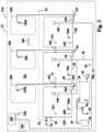
Fig. 1 , awarewash machine 10 includes ahousing 12 defining aninternal chamber 12a that receives wares for cleaning. A conveying device 14 (continuous or intermittent) may be operated to carry wares through the chamber. The chamber includes aspray zone 18 in which a wash liquid (e.g., water and detergent) is recirculatable from atank 20 to aspray assembly 22 for spraying the liquid on wares, as by operation of apump 24. The spray assembly may include one ormore spray pipes 22a with associated spray nozzles. Here, thetank 20 includes a drain opening 26 to adrain path 28 that leads to adrain outlet 28a of the machine. A rinse system 30 is also provided, downstream of thespray assembly 22, in theware conveyance direction 16, and may include arinse spray assembly 32 with associatedspray pipes 32a, where rinse liquid (e.g., fresh water or fresh water and rinse additive) is fed from ahot water booster 34 via operation of a rinse pump 36 (or alternatively by line feed pressure pushing water through the booster). The fresh water may be delivered to the booster from a machine freshwater input connection 38 via operation of afill valve 40. - A delime system is also provided, and includes a source of
delime chemical 42 and adelime pump 44 for selectively feeding delime chemical into thebooster heater 34, such that delime solution (water mixed with the delime chemical) can be delivered to thespray zone 18 andtank 20 by operation of thepump 36. - An
overflow standpipe 46 is provided in the tank and is engaged with the drain opening 26, such that liquid in the tank rising above an overflow level can travel to thedrain path 28 through the standpipe. To fully drain thetank 20, theoverflow standpipe 46 is raised upward from the drain opening 26 (e.g., by manually grasping the overflow standpipe), such that liquid flows directly from the tank into the drain opening 26 and along thepath 28. - A tank
maintenance fill path 50 may also be provided for delivering water from a machine hotwater input connection 52 into thetank 20 via operation of avalve 54. - The machine includes a
controller 100 configured for carrying out various operations of the machine via operation of the machine components. As used herein, the term controller is intended to broadly encompass any circuit (e.g., solid state, application specific integrated circuit (ASIC), an electronic circuit, a combinational logic circuit, a field programmable gate array (FPGA)), processor(s) (e.g., shared, dedicated, or group - including hardware or software that executes code), software, firmware and/or other components, or a combination of some or all of the above, that carries out the control functions of the machine or the control functions of any component thereof. - The
controller 100 may be configured with one or more ware cleaning modes (e.g., spraying wash liquid and rinse liquid on wares moving through thechamber 12a). Thecontroller 100 is also configured with at least one delime operation mode. In the delime operation mode, the delime system is controlled to carry out a delime operation in which the controller delivers delime solution into the tank andspray zone 18 for descaling/deliming of surfaces in the spray zone. - By way of example, delime solution may be made in the
booster 34 in a batchwise process or manner, by delivering delime chemical into thebooster 34 viapump 44, heating the delime solution in the booster to a set temperature (e.g., to 140F), and then pumping the delime solution, via therinse pump 36, to spray through thespray pipes 32a and fill the machine tank(s) 20. The delime solution fills thetank 20 and may be recirculated by thepump 24 for deliming the tank, internal wall surfaces, thetank heater 20a, etc. During a delime circulation process over a set time period, this recirculation may take place continuously, or intermittently with dwell times included. In embodiments, delime chemical could alternatively be delivered directly into thetank 20 without heating in thebooster 34. - After the delime solution circulation process is completed, the delime solution should be drained from the
tank 20, as it is undesirable to allow the acidic delime solution to sit in the tank for an excessive time period. For this purpose, the machine may include a user interface 102 (e.g., HMI with a display screen) and the controller may effect display of a drain machine alert on the user interface informing the operator that thetank 20 must be drained (e.g., by lifting theoverflow pipe 46, or by manual control of a drain valve (not shown)). Before the drain machine alert, any delime solution in thebooster 34 may be cleared via operation of thepump 36 to empty the booster 34 (without adding further delime chemical to the booster). - The
controller 100 is configured to monitor the machine to determine whether a tank drain step takes place to drain delime solution from thetank 20. In embodiments, if the tank drain does not take place, the controller automatically carries out an operation to reduce acidity (increase pH) of the delime solution by at least one of (i) causing delivery of fresh water into the tank to dilute the solution in the tank (e.g., through thebooster 34, and/or directly to the tank via line 50) or (ii) causing addition of detergent to the tank to effect some neutralization of the liquid in the tank (e.g., by adetergent feed line 56 that feeds from adetergent source 57 via a detergent pump 59). The amount of fresh water and/or detergent delivered can be controlled based upon known or expected acidity of the delime solution and the volume in thetank 20, or in tank sensors (e.g., pH meter 61) could also be used to monitor the changing acidity level. Thepump 24 can also be selectively operated as part of this operation to reduce acidity. - In embodiments, the
controller 100 is configured such that, during the delime operation, a circulation process is carried out in which the delime solution is recirculated, continuously or intermittently, from the tank through thespray assembly 22, and thecontroller 100 determines whether a tank drain operation took place after conclusion of the circulation process. The controller may be configured such that, if a tank drain operation does not take place within a set time period (e.g., 10 minutes, 20 minutes, 30 minutes or 40 minutes) after conclusion of the circulation process, the controller automatically carries out the operation to reduce acidity. Thus, the timeout of the set time period acts as a triggering event for the acidity reduction process in such embodiments. Moreover, the controller may be configured such that, after the operation to reduce acidity takes place, a lockout is initiated such that operation in the ware cleaning mode is prevented unless and until a tank drain operation is carried out (e.g., even if the machine is powered off and then powered on again). The controller may cause continued display of the machine drain alert to advise operator(s) to drain the tank during the lockout of the ware cleaning mode. - In embodiments, the
controller 100 is configured to automatically carry out the operation to reduce acidity before initiating the machine drain alert. In such embodiments, the completion of a delime circulation/wash cycle timer acts as the triggering event for the acidity reduction process. However, in some implementations the acidity reduction process could overlap, in whole or in part, with an end portion of the delime circulation, in which case the triggering event for the acidity reduction process would be reaching some intermediate time point of the delime circulation/wash timer (e.g., 90% of the delime circulation/wash timer completed). In either case, after the acidity reduction operation is completed and the delime circulation/wash timer is completed, the controller initiates the machine drain alert and the ware cleaning mode lockout. The controller may be configured such that, if a tank drain operation does not take place within a set time period (e.g., 10 minutes, 20 minutes, 30 minutes or 40 minutes) after initiation of the machine drain alert, the controller powers down the machine. In such embodiments, the controller is configured such that, on a next power up of the machine, the controller remains in the delime operation mode and reinitiates the machine drain alert and reinitiates or maintains the ware cleaning mode lockout such that operation in the ware cleaning mode is prevented unless and until a tank drain operation is carried out. - In embodiments, the determination of whether a tank a drain operation took place is based upon at least one of (i) monitoring of a level of liquid in the tank (e.g., via a sensor 60), (ii) monitoring a flow of liquid along the
drain path 28 from the tank (e.g., via a sensor 62) or (iii) monitoring a condition of a component associated with a drain path from the tank (e.g., via asensor 64 that detects position of the overflow standpipe 46). -
Figs. 2 and3 show machine embodiments 110 and 210 with multiple tanks (e.g., anupstream prewash tank 120 inFig. 2 and both anupstream prewash tank 120 and a downstreampower wash tank 220 inFig. 3 ). Each additional tank includes arespective heater overflow standpipe circulation pump spray pipes sensors overflow paths 302. These multi-tank machines may include additional feed paths for delivery of delime chemical or delime solution to the tanks, without passing through thebooster 34. Each tank may, in some implementations, also include its owndetergent feed line 56. In such machines, thecontroller 100 may be configured to monitor and verify that all tanks are properly drained of delime solution before clearing the ware cleaning mode lockout. - In one embodiment, the
controller 100 is configured to such that in the delime operation mode an associated delime operation or cycle is carried out as follows. - An operator accesses the delime operation mode by pressing a displayed "DELIME" button on the
user interface 102 with the machine powered on or off. Alternatively, the delime operation mode can also be accessed by entering a "manager" menu via theuser interface 102 and scrolling to the delime operation cycle. - The operator is then prompted via the
user interface 102 to confirm the start of the delime operation or cycle. To initiate, the operator selects a "yes" button and presses a displayed Enter button. - Next, the operator is notified by a user interface message to clean the strainers and baskets associated with the machine tank(s). Interlocks associated with one or more doors (e.g., 10a, 10b 10c) on the housing will be open to allow the doors to be opened for internal access to the machine. Once baskets and strainers are cleaned, the operator places them back into the machine. The operator then selects "yes" and presses the displayed Enter button to confirm completion of strainer and basket cleaning.
- The operator is then notified via a
user interface 102 message to drain the machine. The operator will then pull the standpipe(s) 46, 146, 246 as needed to drain all machine tank(s). The user interface shows that the machine is draining and may display progress of draining (e.g., by using tank water level sensors to track the draining). Once the machine has been fully drained, the user interface displays a message instructing the operator close the tank drains (e.g., replace standpipes) and themachine access doors 300. The door interlocks are then closed. - The booster fill
valve 40 is then opened and thedelime pump 44 energized to add delime chemical into thebooster 34, creating the delime solution. - Once the booster water level has reached a set point (e.g., detected by sensor(s) or based upon a known filling time), the rinse
pump 36 is energized to deliver the delime solution to the tank(s) (e.g., via thespray arm 32a). During booster filling, thedelime pump 44 is operated so that the delime solution is added to thebooster 34 periodically to avoid having too strong of a concentration in the booster tank. Rinse pump operation is delayed/stopped until the booster is full and the rinsepump 36 then operates and empties the booster. While emptying the booster, thedelime pump 44 remains off so that no delime solution is added. Once thebooster 34 is empty, thepump 36 is turned off and the fill of the booster takes place again by opening thevalve 40 and periodically operating thedelime pump 44 to add delime chemical. This process will repeat until all tank(s) are considered full (e.g., as detected by water level sensor(s)). - Once the controller identifies that all tanks are full, a delime wash cycle is initiated and "Delime Ongoing" is displayed on the
user interface 102. The wash pumps 24, 124, 224 are operated (continuously or intermittently/periodically (regular or irregular dwell time periods between pump operation) so that the pumps associated with all tanks present in the machine operate to circulate the delime solution for the purpose of deliming. - The length of the delime wash cycle is controlled by a delime circulation/wash cycle timer. Once the delime circulation/wash cycle timer is reached or times out, the wash pump(s) 24, 124, 224 are stopped and a delime dilution operation begins, during which the user interface displays a rinse cycle in process message. In the delime dilution operation, fresh water is added to dilute the delime solution in the tanks, and thus operates as an acidity reduction process that is triggered by completion of the delime circulation/wash cycle timer. Here, the tank fill
valve 54 is opened to provide a direct flow of fresh water (with no delime chemical) into the tank(s). The rinsepump 36 is also operated to empty the booster and thebooster fill valve 40 is opened to deliver fresh water into the booster, but thedelime pump 44 remains off so that no further delime chemical is added. This assures clearing of delime chemical from the booster. In some cases, thebooster 34 may be purged before the tank fillvalve 54 is opened. The acidity reduction process is carried out for a specified time according to a delime dilution timer. The specified time is preset according to a known volume of the machine tank(s) and a known concentration of delime chemical that was added. - After completion of the delime dilution timer, a countdown timer is displayed on the user interface along with an operator instruction to drain the machine. If machine is not drained at the completion of the countdown timer, the machine automatically powers down.
- At the next machine startup, an operator notification is displayed instructing the operator to drain the machine. Detection of actual draining of all machine tanks is necessary to complete the delime operation or cycle. This effectively locks out the ware cleaning mode(s) of the machine until the tank(s) have been drained as the last step of the delime operation or cycle.
- As discussed previously, in an alternative implementation, at the completion of the delime circulation/wash timer, the drain tank message could first be implemented and, if draining does not occur within a specified drain timer, the timeout of the specified drain timer could act as the trigger for the acidity reduction process.
- Figs. 4-7 show timing diagrams for parts of an exemplary delime operation. In particular, Fig. 4 shows Initial Preparation, Batchwise Making of Delime Solution in Booster and Transfer to Connecting Tank(s). Fig. 5 shows Circulation of Delime Solution by the Various Wash Pump(s) in the Connecting Tank(s) in a Regular ON/OF Manner. Fig. 6 shows Batchwise Diluting of Spent Delime Solution in the Booster, Tanks with the Various Wash Pump(s) on at Some Predetermined Time and End of the Delime process (note that the booster fill valve was on to purge the booster into the tanks before the maintenance fill to further dilute the tanks for the above case). Fig. 7 shows Batchwise Diluting of Spent Delime Solution in the Booster and Tanks with the Various Wash Pump(s) ON at Some Predetermined Time.
- It is to be clearly understood that the above description is intended by way of illustration and example only, is not intended to be taken by way of limitation, and that other changes and modifications are possible.
Claims (15)
- A warewash machine for washing wares, comprising:- a chamber for receiving wares, the chamber having at least one spray zone in which a liquid is recirculatable from a tank to a spray assembly for spraying the liquid on wares;- a delime system configured for delivering a delime solution to the tank;- a controller configured for operation in at least one ware cleaning mode and at least one delime operation mode, wherein, in the delime operation mode, the delime system is controlled to carry out a delime cycle in which the controller:- controls the delime system to deliver delime solution into the tank and then circulates the delime solution; and- carries out an acidity reduction process to reduce acidity of the delime solution by at least one of (i) causing delivery of fresh water into the tank to dilute the delime solution in the tank or (ii) causing delivery of detergent into to the tank to effect some neutralization of the delime solution in the tank.
- The warewash machine of claim 1,
wherein the controller is configured such that the acidity reduction process is carried out based upon a triggering event. - The warewash machine of claim 2,
wherein the controller is configured such that the triggering event is one of (i) conclusion of a delime wash/circulation timer or (ii) reaching an intermediate point of a delime wash/circulation timer. - The warewash machine of claim 3,
wherein the controller is configured such that, after completion of the acidity reduction process, a drain tank message is displayed on a user interface. - The warewash machine of claim 4,
wherein the controller is configured to monitor for draining of the tank and, if the tank is not drained within a specified time period, the machine is powered down. - The warewash machine of claim 5,
wherein the controller is configured such that, upon a next power up of the machine, the drain tank message is displayed on the user interface. - The warewash machine of claim 4,
wherein the controller is configured to monitor for draining of the tank, and operation of the warewash machine in the ware cleaning mode is prevented until draining of the tank is detected. - The warewash machine of claim 7,
wherein the controller monitors for draining of the tank by one of (i) monitoring of a level of liquid in the tank, (ii) monitoring a flow of liquid along a drain path from the tank or (iii) monitoring a condition of an overflow standpipe of the tank. - The warewash machine of claim 7,
wherein the tank includes a drain opening to a drain path, and an overflow standpipe removably engaged with the drain opening, and draining of the tank requires manual lifting of the overflow standpipe. - A warewash machine for washing wares, comprising:- a chamber for receiving wares, the chamber having at least one spray zone in which a liquid is recirculatable from a tank to a spray assembly for spraying the liquid on wares, the tank including a drain component that must be manually moved in order to drain the tank;- a delime system configured for delivering a delime solution to the tank;- a controller configured for operation in at least one ware cleaning mode and at least one delime operation mode, wherein, in the delime operation mode, the delime system is controlled to carry out a delime cycle in which the controller:- controls the delime system to deliver delime solution into the tank and then circulates the delime solution; and- monitors whether drainage of the tank occurs after completion of circulation of the delime solution and initiates and maintains a lockout of the ware cleaning mode until drainage of the tank occurs.
- The warewash machine of claim 10,
wherein at least one liquid level sensor is associated with the tank and the controller monitors output of the liquid level sensor to determine whether drainage of the tank occurs. - The warewash machine of claim 10,
wherein the controller is configured such that, as part of the delime cycle, an acidity reduction process is carried out to reduce acidity of the delime solution by at least one of (i) causing delivery of fresh water into the tank to dilute the delime solution in the tank or (ii) causing delivery of detergent into to the tank to effect some neutralization of the delime solution in the tank. - The warewash machine of claim 12,
wherein the controller is configured such that the acidity reduction process is carried out based upon a triggering event. - The warewash machine of claim 3,
wherein the controller is configured such that the triggering even is one of (i) conclusion of a delime wash/circulation timer or (ii) reaching an intermediate point of a delime wash/circulation timer or (iii) identifying that drainage of the tank did not occur within a set time period. - The warewash machine of claim 10,
wherein the drain component is an overflow standpipe.
Applications Claiming Priority (2)
| Application Number | Priority Date | Filing Date | Title |
|---|---|---|---|
| US202363609563P | 2023-12-13 | 2023-12-13 | |
| US18/969,969 US20250194892A1 (en) | 2023-12-13 | 2024-12-05 | Warewasher deliming/descaling system |
Publications (1)
| Publication Number | Publication Date |
|---|---|
| EP4570157A1 true EP4570157A1 (en) | 2025-06-18 |
Family
ID=93853314
Family Applications (1)
| Application Number | Title | Priority Date | Filing Date |
|---|---|---|---|
| EP24218634.4A Pending EP4570157A1 (en) | 2023-12-13 | 2024-12-10 | Warewasher deliming/descaling system |
Country Status (5)
| Country | Link |
|---|---|
| US (1) | US20250194892A1 (en) |
| EP (1) | EP4570157A1 (en) |
| CN (1) | CN120130878A (en) |
| CA (1) | CA3259000A1 (en) |
| MX (1) | MX2024015243A (en) |
Citations (6)
| Publication number | Priority date | Publication date | Assignee | Title |
|---|---|---|---|---|
| DE19906791A1 (en) * | 1999-02-18 | 2000-08-24 | Miele & Cie | Program-controlled dishwashing machine is designed as combination apparatus for selectable operation as tank rinsing machine or as fresh water rinsing machine |
| US20020096192A1 (en) * | 2001-01-19 | 2002-07-25 | Reichold Kurt A. | Automatic system and method for removing mineral deposits from a dishwasher |
| US20110126861A1 (en) * | 2009-08-24 | 2011-06-02 | Electrolux Professional Spa AND Ecolab, Inc. | Descaling arrangement for a dishwasher, and associated apparatus and method |
| US20150059809A1 (en) * | 2013-08-30 | 2015-03-05 | Electrolux Professional S.P.A. | Washing machine comprising a de-scaling apparatus |
| US20160324390A1 (en) * | 2013-12-27 | 2016-11-10 | Hoshizaki Denki Kabushiki Kaisha | Washer |
| US20170164811A1 (en) * | 2012-08-21 | 2017-06-15 | Premark Feg L.L.C. | Warewash machine with descaling/deliming system and method |
-
2024
- 2024-12-05 US US18/969,969 patent/US20250194892A1/en active Pending
- 2024-12-09 MX MX2024015243A patent/MX2024015243A/en unknown
- 2024-12-09 CA CA3259000A patent/CA3259000A1/en active Pending
- 2024-12-10 EP EP24218634.4A patent/EP4570157A1/en active Pending
- 2024-12-12 CN CN202411830105.XA patent/CN120130878A/en active Pending
Patent Citations (6)
| Publication number | Priority date | Publication date | Assignee | Title |
|---|---|---|---|---|
| DE19906791A1 (en) * | 1999-02-18 | 2000-08-24 | Miele & Cie | Program-controlled dishwashing machine is designed as combination apparatus for selectable operation as tank rinsing machine or as fresh water rinsing machine |
| US20020096192A1 (en) * | 2001-01-19 | 2002-07-25 | Reichold Kurt A. | Automatic system and method for removing mineral deposits from a dishwasher |
| US20110126861A1 (en) * | 2009-08-24 | 2011-06-02 | Electrolux Professional Spa AND Ecolab, Inc. | Descaling arrangement for a dishwasher, and associated apparatus and method |
| US20170164811A1 (en) * | 2012-08-21 | 2017-06-15 | Premark Feg L.L.C. | Warewash machine with descaling/deliming system and method |
| US20150059809A1 (en) * | 2013-08-30 | 2015-03-05 | Electrolux Professional S.P.A. | Washing machine comprising a de-scaling apparatus |
| US20160324390A1 (en) * | 2013-12-27 | 2016-11-10 | Hoshizaki Denki Kabushiki Kaisha | Washer |
Also Published As
| Publication number | Publication date |
|---|---|
| US20250194892A1 (en) | 2025-06-19 |
| MX2024015243A (en) | 2025-07-01 |
| CA3259000A1 (en) | 2025-10-31 |
| CN120130878A (en) | 2025-06-13 |
Similar Documents
| Publication | Publication Date | Title |
|---|---|---|
| US8193470B1 (en) | Self-cleaning convection oven | |
| EP1351598B1 (en) | Automatic system and method for removing mineral deposits from a dishwasher | |
| US4147559A (en) | Apparatus for rinsing and chemically sanitizing food ware items | |
| EP2289385B1 (en) | Dishwasher comprising a descaling arrangement | |
| CN107920711B (en) | Dishwashing Machine Cleaning Notice and In-Situ Dilution Process | |
| US8808463B2 (en) | Method of recycling a rinse aid to precondition soils | |
| US20170164811A1 (en) | Warewash machine with descaling/deliming system and method | |
| US4228813A (en) | Low temperature conveyor, rack-type dishwasher | |
| US20220061626A1 (en) | Warewash machine drain down process and associated warewash machine | |
| KR101217996B1 (en) | An auto cleaning stopping method for a steam convection oven | |
| US20250194892A1 (en) | Warewasher deliming/descaling system | |
| USRE30537E (en) | Method for rinsing and chemically sanitizing food ware items | |
| US20140069465A1 (en) | Method of using liquid in a dishwasher | |
| CN117338167B (en) | Method and device for controlling cleaning of inner chamber of cooking equipment and cooking equipment | |
| EP1875851A1 (en) | Automated washer with de-scaling | |
| US20190001378A1 (en) | Mobile clean-in-place unit for warewash machines and related methods | |
| EP3364847B1 (en) | Warewasher idling system and method | |
| USRE30478E (en) | Apparatus for rinsing and chemically sanitizing food ware items | |
| JP5491998B2 (en) | washing machine | |
| JP2024046733A (en) | CLEANING METHOD, CLEANING APPARATUS, COOKING UTENSIL, AND READABLE STORAGE MEDIUM | |
| CN119014775A (en) | Dishwasher and control method thereof | |
| US20220026072A1 (en) | Apparatus for Cooking Foods and a Method for Operating the Apparatus | |
| US20160345796A1 (en) | Warewash machine with controlled retention of liquid in suspension | |
| CN119014774A (en) | Dishwasher and control method thereof |
Legal Events
| Date | Code | Title | Description |
|---|---|---|---|
| PUAI | Public reference made under article 153(3) epc to a published international application that has entered the european phase |
Free format text: ORIGINAL CODE: 0009012 |
|
| STAA | Information on the status of an ep patent application or granted ep patent |
Free format text: STATUS: REQUEST FOR EXAMINATION WAS MADE |
|
| 17P | Request for examination filed |
Effective date: 20241210 |
|
| AK | Designated contracting states |
Kind code of ref document: A1 Designated state(s): AL AT BE BG CH CY CZ DE DK EE ES FI FR GB GR HR HU IE IS IT LI LT LU LV MC ME MK MT NL NO PL PT RO RS SE SI SK SM TR |