EP4570126A1 - Slide rail assembly - Google Patents
Slide rail assembly Download PDFInfo
- Publication number
- EP4570126A1 EP4570126A1 EP24200766.4A EP24200766A EP4570126A1 EP 4570126 A1 EP4570126 A1 EP 4570126A1 EP 24200766 A EP24200766 A EP 24200766A EP 4570126 A1 EP4570126 A1 EP 4570126A1
- Authority
- EP
- European Patent Office
- Prior art keywords
- rail
- slide
- assisting device
- wall
- slide assisting
- Prior art date
- Legal status (The legal status is an assumption and is not a legal conclusion. Google has not performed a legal analysis and makes no representation as to the accuracy of the status listed.)
- Pending
Links
Images




Classifications
-
- A—HUMAN NECESSITIES
- A47—FURNITURE; DOMESTIC ARTICLES OR APPLIANCES; COFFEE MILLS; SPICE MILLS; SUCTION CLEANERS IN GENERAL
- A47B—TABLES; DESKS; OFFICE FURNITURE; CABINETS; DRAWERS; GENERAL DETAILS OF FURNITURE
- A47B88/00—Drawers for tables, cabinets or like furniture; Guides for drawers
- A47B88/40—Sliding drawers; Slides or guides therefor
- A47B88/49—Sliding drawers; Slides or guides therefor with double extensible guides or parts
- A47B88/493—Sliding drawers; Slides or guides therefor with double extensible guides or parts with rollers, ball bearings, wheels, or the like
-
- F—MECHANICAL ENGINEERING; LIGHTING; HEATING; WEAPONS; BLASTING
- F16—ENGINEERING ELEMENTS AND UNITS; GENERAL MEASURES FOR PRODUCING AND MAINTAINING EFFECTIVE FUNCTIONING OF MACHINES OR INSTALLATIONS; THERMAL INSULATION IN GENERAL
- F16C—SHAFTS; FLEXIBLE SHAFTS; ELEMENTS OR CRANKSHAFT MECHANISMS; ROTARY BODIES OTHER THAN GEARING ELEMENTS; BEARINGS
- F16C29/00—Bearings for parts moving only linearly
- F16C29/005—Guide rails or tracks for a linear bearing, i.e. adapted for movement of a carriage or bearing body there along
-
- F—MECHANICAL ENGINEERING; LIGHTING; HEATING; WEAPONS; BLASTING
- F16—ENGINEERING ELEMENTS AND UNITS; GENERAL MEASURES FOR PRODUCING AND MAINTAINING EFFECTIVE FUNCTIONING OF MACHINES OR INSTALLATIONS; THERMAL INSULATION IN GENERAL
- F16C—SHAFTS; FLEXIBLE SHAFTS; ELEMENTS OR CRANKSHAFT MECHANISMS; ROTARY BODIES OTHER THAN GEARING ELEMENTS; BEARINGS
- F16C29/00—Bearings for parts moving only linearly
- F16C29/04—Ball or roller bearings
-
- A—HUMAN NECESSITIES
- A47—FURNITURE; DOMESTIC ARTICLES OR APPLIANCES; COFFEE MILLS; SPICE MILLS; SUCTION CLEANERS IN GENERAL
- A47B—TABLES; DESKS; OFFICE FURNITURE; CABINETS; DRAWERS; GENERAL DETAILS OF FURNITURE
- A47B2210/00—General construction of drawers, guides and guide devices
- A47B2210/0002—Guide construction for drawers
- A47B2210/0064—Guide sequencing or synchronisation
- A47B2210/007—Three slide synchronisation
-
- A—HUMAN NECESSITIES
- A47—FURNITURE; DOMESTIC ARTICLES OR APPLIANCES; COFFEE MILLS; SPICE MILLS; SUCTION CLEANERS IN GENERAL
- A47B—TABLES; DESKS; OFFICE FURNITURE; CABINETS; DRAWERS; GENERAL DETAILS OF FURNITURE
- A47B2210/00—General construction of drawers, guides and guide devices
- A47B2210/0002—Guide construction for drawers
- A47B2210/0064—Guide sequencing or synchronisation
- A47B2210/0081—Telescopic drawer rails with stop blocks, e.g. synchronization buffers
Definitions
- the present invention is related to a slide rail assembly.
- US patent number US 6,851,773 B2 discloses a track device for a drawer.
- the track device includes a first track, a second track, a slide-adding member, a retaining member and an unlatching member.
- the slide-adding member is movably mounted between the first track and the second track.
- the retaining member is arranged on the first track.
- the unlatching member is arranged on the second track.
- the second track detached from the first track When the second track detached from the first track is reinserted into the first track, the second track can abut against a hook part of the retaining member through an inclined surface at the rear end of the unlatching member, such that a resilient hook rod of the retaining member can be elastically moved to disengage a hook part on the resilient hook rod and a hook of the slide-adding member from each other.
- the present invention aims at providing a slide rail assembly.
- the slide rail assembly comprises a first rail, a second rail and a slide assisting device.
- the first rail is formed with a passage.
- the second rail is longitudinally movable relative to the first rail.
- the slide assisting device is movably mounted between the first rail and the second rail.
- One of the first rail and the slide assisting device is arranged with an elastic member having a first engaging feature, and the other one of the first rail and the slide assisting device is arranged with a second engaging feature.
- the first engaging feature and the second engaging feature are configured to be engaged with each other in order to prevent the slide assisting device from being moved from a first predetermined position along a retracting direction.
- the second rail comprises an auxiliary part and a driving part.
- the second rail When the second rail detached from the passage of the first rail is reinserted into the passage of the first rail along the retracting direction, the second rail is configured to contact the elastic member through the auxiliary part, in order to move the elastic member to switch from a first state to a second state, so as to disengage the first engaging feature and the second engaging feature from each other.
- the driving part When the second rail is further moved along the retracting direction, the driving part is configured to contact a predetermined feature on the slide assisting device, in order to drive the slide assisting device to move away from the first predetermined position along the retracting direction.
- a slide rail assembly 20 comprises a first rail 22, a second rail 24 and a slide assisting device 26 according to an embodiment of the present invention.
- the slide rail assembly 20 further comprises a third rail 28.
- the first rail 22 (such as a middle rail) is movably mounted between the third rail 28 (such as an outer rail) and the second rail 24 (such as an inner rail).
- the first rail 22, the second rail 24 and the third rail 28 are longitudinally movable relative to each other.
- the X axis is a longitudinal direction (or a length direction or a moving direction of the slide rail)
- the Y axis is a transverse direction (or a lateral direction of the slide rail)
- the Z axis is a vertical direction (or a height direction of the slide rail).
- the third rail 28 has a first end part 28a and a second end part 28b opposite to each other, such as a front end part and a rear end part, but the present invention is not limited thereto.
- the third rail 28 comprises a first wall 30a, a second wall 30b and a longitudinal wall 32 connected between the first wall 30a and the second wall 30b of the third rail 28.
- An auxiliary passage is defined by the first wall 30a, the second wall 30b and the longitudinal wall 32 of the third rail 28 and configured to accommodate the first rail 22.
- An inner side of each of the first wall 30a and the second wall 30b of the third rail 28 is arranged with a ball rolling bar configured to support the first rail 22 for improving sliding smoothness.
- the first rail 22 has a first end part 22a and a second end part 22b opposite to each other, such as a front end part and a rear end part, but the present invention is not limited thereto.
- the first rail 22 comprises a first wall 34a, a second wall 34b and a longitudinal wall 36 connected between the first wall 34a and the second wall 34b of the first rail 22.
- a passage 37 is defined by the first wall 34a, the second wall 34b and the longitudinal wall 36 of the first rail 22 and configured to accommodate the second rail 24.
- the second rail 24 has a first end part 24a and a second end 24b part opposite to each other, such as a front end part and a rear end part, but the present invention is not limited thereto.
- the second rail 24 comprises a first wall 38a, a second wall 38b and a longitudinal wall 40 connected between the first wall 38a and the second wall 38b of the second rail 24.
- the slide assisting device 26 is movably mounted between the first rail 22 and the second rail 24.
- the passage 37 of the first rail 22 is configured to accommodate the slide assisting device 26 and the second rail 24.
- the slide assisting device 26 comprises a plurality of rolling members 44 (such as balls) configured to provide support between the first rail 22 and the second rail 24 in order to improve smoothness of relative movement between the first rail 22 and the second rail 24.
- the slide assisting device 26 comprises a first side part 46a, a second side part 46b and a longitudinal part 48 connected between the first side part 46a and the second side part 46b. Each of the first side part 46a and the second side part 46b is arranged with the plurality of rolling members 44.
- one of the first rail 22 and the slide assisting device 26 is arranged with an elastic member 50.
- the elastic member 50 is connected to the first rail 22 (the longitudinal wall 36 of the first rail 22), and the elastic member 50 has a first engaging feature 52.
- the elastic member 50 further has an engaging structure 33 adjacent to the first engaging feature 52, and a predetermined space is defined between the first engaging feature 52 and the engaging structure 33.
- the first engaging feature 52 and the engaging structure 33 are respectively arranged with a first guiding section 54 and a second guiding section 56 at positions far away from each other (as shown in FIG. 3 ).
- Each of the first guiding section 54 and the second guiding section 56 has an arc surface or an inclined surface, but the present invention is not limited thereto.
- the elastic member 50 comprises a connecting part 58 and an elastic part 60.
- the connecting part 58 is connected (such as fixedly connected) to the first rail 22 (the longitudinal wall 36 of the first rail 22), and the elastic part 60 is extended from the connecting part 58.
- the first engaging feature 52 and the engaging structure 33 are arranged on the elastic part 60 of the elastic member 50. Both the first engaging feature 52 and the engaging structure 33 are protrusions, but the present invention is not limited thereto.
- the other one of the first rail 22 and the slide assisting device 26 is arranged with a second engaging feature 62.
- the slide assisting device 26 is arranged with the second engaging feature 62.
- the first engaging feature 52 and the second engaging feature 62 are configured to be engaged with each other in order to prevent the slide assisting device 26 from being moved from a first predetermined position Kl along a retracting direction D1 relative to the first rail 22 (as shown in FIG. 3 ).
- the slide assisting device 26 when the slide assisting device 26 is located at the first predetermined position K1, the slide assisting device 26 is adjacent to the first end part 22a of the first rail 22.
- the second engaging feature 62 is engaged between the first engaging feature 52 and the engaging structure 33, such that the slide assisting device 26 is prevented from being moved from the first predetermined position K1 along the retracting direction D1 or an opening direction D2 relative to the first rail 22 (as shown in FIG. 3 ).
- the slide assisting device 26 is formed with a first working space M1 and a second working space M2, and the second engaging feature 62 is located between the first working space M1 and the second working space M2.
- the first working space M1 and the second working space M2 correspond to the first engaging feature 52 and the engaging structure 33 respectively.
- the slide assisting device 26 further comprises a predetermined feature 67, and the predetermined feature 67 is a bent section or a protruded section, but the present invention is not limited thereto.
- the second rail 24 comprises an auxiliary part 64 and a driving part 66 (as shown in FIG. 2 ), and the auxiliary part 64 and the driving part 66 are separated from each other by a predetermined longitudinal distance along the longitudinal direction.
- the auxiliary part 64 is closer to the first end part 24a of the second rail 24.
- the driving part 66 is farther away from the first end part 24a of the second rail 24.
- the auxiliary part 64 is arranged with a first guiding feature 68a and a second guiding feature 68b opposite to each other, and each of the first guiding feature 68a and the second guiding feature 68b has an arc surface or an inclined surface, but the present invention is not limited thereto.
- both the auxiliary part 64 and the driving part 66 are protrusions, but the present invention is not limited thereto.
- the first rail 22 is located at an opening position J relative to the third rail 28.
- the first rail 22 is configured to be held at the opening position J through a positioning mechanism.
- the second rail 24 is able to be detached from the passage 37 of the first rail 22 along the opening direction D2, such that the second rail 24 can be located outside the passage 37 of the first rail 22.
- Such configuration is well known to those skilled in the art, no further illustration is provided for simplification.
- the slide assisting device 26 when the second rail 24 is detached from the passage 37 of the first rail 22 along the opening direction D2, the slide assisting device 26 is configured to be moved to the first predetermined position K1 along the opening direction D2 relative to the first rail 22, and the second engaging feature 62 of the slide assisting device 26 is configured to be engaged between the first engaging feature 52 and the engaging structure 33.
- the first engaging feature 52 and the second engaging feature 62 are configured to be engaged with each other to prevent the slide assisting device 26 from being moved from the first predetermined position Kl along the retracting direction D1.
- the second rail 24 when the second rail 24 detached from the passage 37 of the first rail 22 is reinserted into the passage 37 of the first rail 22 along the retracting direction D1, the second rail 24 is configured to contact (or press) the elastic member 50 (the engaging structure 33 of the elastic member 50) through one of the auxiliary part 64 and the driving part 66 (such as the auxiliary part 64), in order to move (or deflect) the elastic member 50 (the elastic part 60 of the elastic member 50) along a predetermined direction L to switch from a first state S1 (an engaged state as shown in FIG. 4 ) to a second state S2 (a disengaged state as shown in FIG.
- the first engaging feature 52 and the second engaging feature 62 are disengaged from each other (for example, the first engaging feature 52 and the second engaging feature 62 are transversely offset from each other without blocking each other along the longitudinal direction).
- the other one of the auxiliary part 64 and the driving part 66 (such as the driving part 66) is configured to contact the predetermined feature 67 on the slide assisting device 26, in order to drive (such as push) the slide assisting device 26 to move away from the first predetermined position K1 along the retracting direction D1.
- the auxiliary part 64 is configured to contact the elastic member 50 (the engaging structure 33 of the elastic member 50) to move the elastic member 50 (the elastic part 60 of the elastic member 50) to switch from the first state S1 (as shown in FIG. 4 ) to the second state S2 (as shown in FIG. 5 ), in order to disengage the first engaging feature 52 and the engaging locking feature 62 from each other.
- the driving part 66 is configured to contact the predetermined feature 67 on the slide assisting device 26 to forcibly drive (such as push) the slide assisting device 26 to move away from the first predetermined position K1 along the retracting direction D1, thereby it can ensure that the slide assisting device 26 can be moved from the first predetermined position K1 along the retracting direction D1.
- the auxiliary part 64 is configured to abut against the second guiding section 56 of the engaging structure 33 through the first guiding feature 68a, in order to move the elastic part 60 of the elastic member 50 to switch from the first state S1 (as shown in FIG. 4 ) to the second state S2 (as shown in FIG. 5 ).
- the slide rail assembly 20 further comprises a working member 70 arranged on the first rail 22, and a predetermined structure 72 is arranged on the second rail 24 (as shown in FIG. 6 , please also refer to FIG. 2 ).
- the predetermined structure 72 is configured to work with the working member 70.
- the working member 70 is pivotally connected to the first rail 22 (the longitudinal wall 36 of the first rail 22) through a shaft member 74.
- the shaft member 74 is arranged in a direction substantially identical to the transverse direction (or the lateral direction of the first rail 22), or the Y-axis direction (please also refer to FIG. 2 ).
- the working member 70 comprises a working part 76.
- the predetermined structure 72 is formed with a space, such as an opening, but the present invention is not limited thereto.
- the predetermined structure 72 is located on or adjacent to the second wall 38b of the second rail 24.
- the rolling members 44 on the first side part 46a are configured to provide support between the first wall 34a of the first rail 22 and the first wall 38a of the second rail 24, and the rolling members 44 on the second side part 46b are configured to provide support between the second wall 34b of the first rail 22 and the second wall 38b of the second rail 24 (as shown in FIG. 6 ) .
- the slide assisting device 26 can be moved from the first predetermined position K1 along the retracting direction D1 to a second predetermined position K2, such that the slide assisting device 26 is adjacent to the second end part 22b of the first rail 22 (as shown in FIG. 7 ) . Furthermore, when the second rail 24 (and the first rail 22) is located at a retracted position R relative to the third rail 28 and when the slide assisting device 26 is located at the second predetermined position K2, the slide rail assembly 20 is in a retracted state (such as a fully retracted state shown in FIG. 7 ) .
- the rolling members 44 of the slide assisting device 26 are configured to provide support between the first rail 22 and the second rail 24.
- the rolling members 44 of the slide assisting device 26 are configured to provide support between the first wall 34a of the first rail 22 and the first wall 38a of the second rail 24, and to provide support between the second wall 34b of the first rail 22 and the second wall 38b of the second rail 24, so as to keep a predetermined gap G between the first rail 22 (the second wall 34b of the first rail 22) and the second rail 24 (the second wall 38b of the second rail 24) as shown in FIG. 7 .
- reliability of the predetermined structure 72 working with the working member 70 can be improved.
- the first rail 22 is further arranged with at least one blocking part 77.
- the blocking part 77 is configured to block the slide assisting device 26 in order to prevent the slide assisting device 26 from being further moved along the retracting direction D1.
- the slide rail assembly 20 further comprises an elastic feature 78 configured to provide an elastic force to the working member 70.
- an elastic feature 78 configured to provide an elastic force to the working member 70.
- the working member 70 and the predetermined structure 72 are configured to be engaged with each other, such that the first rail 22 is configured to be synchronously moved with the second rail 24 relative to the third rail 28 along the opening direction D2.
- the second wall 38b of the second rail 24 no longer supports the working part 76 of the working member 70, and the elastic feature 78 is configured to release the predetermined elastic force to drive the working member 70 to rotate, such that the working part 76 of the working member 70 is configured to enter the space provided by the predetermined structure 72.
- the working part 76 of the working member 70 and the predetermined structure 72 are engaged with each other, in order to allow the second rail 24 and the first rail 22 to be synchronously moved along the opening direction D2 relative to the third rail 28 (a predetermined wall 80 of the predetermined structure 72 beside the space is configured to push the working part 76 of the working member 70 when the second rail 24 is moved along the opening direction D2) .
- the synchronous movement configuration between the second rail 24 and the first rail 22 can be disabled by a predetermined structure on the third rail 28.
- Such configuration is well known to those skilled in the art, no further illustration is provided for simplification.
- the slide rail assembly 20 according to the embodiment of the present invention has the following technical features:
Landscapes
- Engineering & Computer Science (AREA)
- General Engineering & Computer Science (AREA)
- Mechanical Engineering (AREA)
- Bearings For Parts Moving Linearly (AREA)
- Seats For Vehicles (AREA)
- Drawers Of Furniture (AREA)
Abstract
A slide rail assembly (20) includes a first rail (22), a second rail (24) and a slide assisting device (26) . The slide assisting device (26) is movably mounted between the first rail (22) and the second rail (24). One of the first rail (22) and the slide assisting device (26) is arranged with an elastic member (50) having a first engaging feature (52) . The other one of the first rail (22) and the slide assisting device (26) is arranged with a second engaging feature (62). The first engaging feature (52) and the second engaging feature (62) are configured to be engaged with each other in order to prevent the slide assisting device (26) from being moved from a predetermined position. The second rail (24) includes at least one auxiliary part (64) configured to disengage the first engaging feature (52) and the second engaging feature (62) from each other.
Description
- The present invention is related to a slide rail assembly.
- US patent number
US 6,851,773 B2 discloses a track device for a drawer. The track device includes a first track, a second track, a slide-adding member, a retaining member and an unlatching member. The slide-adding member is movably mounted between the first track and the second track. The retaining member is arranged on the first track. The unlatching member is arranged on the second track. When the second track detached from the first track is reinserted into the first track, the second track can abut against a hook part of the retaining member through an inclined surface at the rear end of the unlatching member, such that a resilient hook rod of the retaining member can be elastically moved to disengage a hook part on the resilient hook rod and a hook of the slide-adding member from each other. - However, for different market requirements, it is important to develop various slide rail products.
- This in mind, the present invention aims at providing a slide rail assembly.
- This is achieved by a slide rail assembly according to
claim 1. The dependent claims pertain to corresponding further developments and improvements. - As will be seen more clearly from the detailed description following below, the slide rail assembly comprises a first rail, a second rail and a slide assisting device. The first rail is formed with a passage. The second rail is longitudinally movable relative to the first rail. The slide assisting device is movably mounted between the first rail and the second rail. One of the first rail and the slide assisting device is arranged with an elastic member having a first engaging feature, and the other one of the first rail and the slide assisting device is arranged with a second engaging feature. The first engaging feature and the second engaging feature are configured to be engaged with each other in order to prevent the slide assisting device from being moved from a first predetermined position along a retracting direction. The second rail comprises an auxiliary part and a driving part. When the second rail detached from the passage of the first rail is reinserted into the passage of the first rail along the retracting direction, the second rail is configured to contact the elastic member through the auxiliary part, in order to move the elastic member to switch from a first state to a second state, so as to disengage the first engaging feature and the second engaging feature from each other. When the second rail is further moved along the retracting direction, the driving part is configured to contact a predetermined feature on the slide assisting device, in order to drive the slide assisting device to move away from the first predetermined position along the retracting direction.
- In the following, the invention is further illustrated by way of example, taking reference to the accompanying drawings thereof:
-
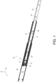
FIG. 1 is a diagram showing a slide rail assembly according to an embodiment of the present invention; -
FIG. 2 is an exploded view of the slide rail assembly comprising a first rail, a second rail and a third rail according to the embodiment of the present invention; -
FIG. 3 is a diagram showing a slide assisting device located at a first predetermined position to be engaged with the first rail according to an embodiment of the present invention; -
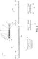
FIG. 4 is a diagram showing the first rail located at an opening position relative to the third rail with the second rail being detached from a passage of the first rail according to the embodiment of the present invention; -
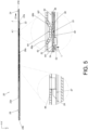
FIG. 5 is a diagram showing the first rail located at the opening position relative to the third rail with the second rail being inserted into the passage of the first rail along a retracting direction according to the embodiment of the present invention; -
FIG. 6 is a diagram showing the first rail located at the opening position relative to the third rail with the second rail being inserted into the passage of the first rail along the retracting direction in another viewing angle according to the embodiment of the present invention; -
FIG. 7 is a diagram showing the slide rail assembly being in a retracted state according to the embodiment of the present invention; and -
FIG. 8 is a diagram showing the second rail and the first rail configured to be synchronously moved relative to the third rail along an opening direction according to the embodiment of the present invention. - As shown in
FIG. 1 andFIG. 2 , aslide rail assembly 20 comprises afirst rail 22, asecond rail 24 and aslide assisting device 26 according to an embodiment of the present invention. Preferably, theslide rail assembly 20 further comprises athird rail 28. The first rail 22 (such as a middle rail) is movably mounted between the third rail 28 (such as an outer rail) and the second rail 24 (such as an inner rail). Thefirst rail 22, thesecond rail 24 and thethird rail 28 are longitudinally movable relative to each other. In the present embodiment, the X axis is a longitudinal direction (or a length direction or a moving direction of the slide rail), the Y axis is a transverse direction (or a lateral direction of the slide rail), and the Z axis is a vertical direction (or a height direction of the slide rail). - The
third rail 28 has afirst end part 28a and asecond end part 28b opposite to each other, such as a front end part and a rear end part, but the present invention is not limited thereto. Thethird rail 28 comprises afirst wall 30a, asecond wall 30b and alongitudinal wall 32 connected between thefirst wall 30a and thesecond wall 30b of thethird rail 28. An auxiliary passage is defined by thefirst wall 30a, thesecond wall 30b and thelongitudinal wall 32 of thethird rail 28 and configured to accommodate thefirst rail 22. An inner side of each of thefirst wall 30a and thesecond wall 30b of thethird rail 28 is arranged with a ball rolling bar configured to support thefirst rail 22 for improving sliding smoothness. - The
first rail 22 has afirst end part 22a and asecond end part 22b opposite to each other, such as a front end part and a rear end part, but the present invention is not limited thereto. Thefirst rail 22 comprises afirst wall 34a, asecond wall 34b and alongitudinal wall 36 connected between thefirst wall 34a and thesecond wall 34b of thefirst rail 22. Apassage 37 is defined by thefirst wall 34a, thesecond wall 34b and thelongitudinal wall 36 of thefirst rail 22 and configured to accommodate thesecond rail 24. - The
second rail 24 has afirst end part 24a and asecond end 24b part opposite to each other, such as a front end part and a rear end part, but the present invention is not limited thereto. Thesecond rail 24 comprises afirst wall 38a, asecond wall 38b and alongitudinal wall 40 connected between thefirst wall 38a and thesecond wall 38b of thesecond rail 24. - The
slide assisting device 26 is movably mounted between thefirst rail 22 and thesecond rail 24. Specifically, thepassage 37 of thefirst rail 22 is configured to accommodate theslide assisting device 26 and thesecond rail 24. Preferably, theslide assisting device 26 comprises a plurality of rolling members 44 (such as balls) configured to provide support between thefirst rail 22 and thesecond rail 24 in order to improve smoothness of relative movement between thefirst rail 22 and thesecond rail 24. Theslide assisting device 26 comprises afirst side part 46a, asecond side part 46b and alongitudinal part 48 connected between thefirst side part 46a and thesecond side part 46b. Each of thefirst side part 46a and thesecond side part 46b is arranged with the plurality of rollingmembers 44. - As shown in
FIG. 2 andFIG. 3 , one of thefirst rail 22 and theslide assisting device 26 is arranged with anelastic member 50. In the present embodiment, theelastic member 50 is connected to the first rail 22 (thelongitudinal wall 36 of the first rail 22), and theelastic member 50 has a firstengaging feature 52. Moreover, theelastic member 50 further has an engagingstructure 33 adjacent to the firstengaging feature 52, and a predetermined space is defined between the firstengaging feature 52 and the engagingstructure 33. The firstengaging feature 52 and the engagingstructure 33 are respectively arranged with afirst guiding section 54 and asecond guiding section 56 at positions far away from each other (as shown inFIG. 3 ). Each of thefirst guiding section 54 and thesecond guiding section 56 has an arc surface or an inclined surface, but the present invention is not limited thereto. - Preferably, the
elastic member 50 comprises a connectingpart 58 and anelastic part 60. The connectingpart 58 is connected (such as fixedly connected) to the first rail 22 (thelongitudinal wall 36 of the first rail 22), and theelastic part 60 is extended from the connectingpart 58. - Preferably, the first
engaging feature 52 and the engagingstructure 33 are arranged on theelastic part 60 of theelastic member 50. Both the firstengaging feature 52 and the engagingstructure 33 are protrusions, but the present invention is not limited thereto. - The other one of the
first rail 22 and theslide assisting device 26 is arranged with a secondengaging feature 62. In the present embodiment, theslide assisting device 26 is arranged with the secondengaging feature 62. The firstengaging feature 52 and the secondengaging feature 62 are configured to be engaged with each other in order to prevent theslide assisting device 26 from being moved from a first predetermined position Kl along a retracting direction D1 relative to the first rail 22 (as shown inFIG. 3 ). - Preferably, when the
slide assisting device 26 is located at the first predetermined position K1, theslide assisting device 26 is adjacent to thefirst end part 22a of thefirst rail 22. - Preferably, when the
slide assisting device 26 is located at the first predetermined position K1, the secondengaging feature 62 is engaged between the firstengaging feature 52 and the engagingstructure 33, such that theslide assisting device 26 is prevented from being moved from the first predetermined position K1 along the retracting direction D1 or an opening direction D2 relative to the first rail 22 (as shown inFIG. 3 ). - Preferably, the
slide assisting device 26 is formed with a first working space M1 and a second working space M2, and the secondengaging feature 62 is located between the first working space M1 and the second working space M2. When theslide assisting device 26 is located at the first predetermined position K1, the first working space M1 and the second working space M2 correspond to the firstengaging feature 52 and the engagingstructure 33 respectively. - Preferably, the
slide assisting device 26 further comprises apredetermined feature 67, and thepredetermined feature 67 is a bent section or a protruded section, but the present invention is not limited thereto. - The
second rail 24 comprises anauxiliary part 64 and a driving part 66 (as shown inFIG. 2 ), and theauxiliary part 64 and the drivingpart 66 are separated from each other by a predetermined longitudinal distance along the longitudinal direction. Compared with the drivingpart 66, theauxiliary part 64 is closer to thefirst end part 24a of thesecond rail 24. In other words, the drivingpart 66 is farther away from thefirst end part 24a of thesecond rail 24. - Preferably, the
auxiliary part 64 is arranged with afirst guiding feature 68a and asecond guiding feature 68b opposite to each other, and each of thefirst guiding feature 68a and thesecond guiding feature 68b has an arc surface or an inclined surface, but the present invention is not limited thereto. - Preferably, both the
auxiliary part 64 and the drivingpart 66 are protrusions, but the present invention is not limited thereto. - As shown in
FIG. 4 , thefirst rail 22 is located at an opening position J relative to thethird rail 28. Preferably, thefirst rail 22 is configured to be held at the opening position J through a positioning mechanism. In addition, thesecond rail 24 is able to be detached from thepassage 37 of thefirst rail 22 along the opening direction D2, such that thesecond rail 24 can be located outside thepassage 37 of thefirst rail 22. Such configuration is well known to those skilled in the art, no further illustration is provided for simplification. - Moreover, when the
second rail 24 is detached from thepassage 37 of thefirst rail 22 along the opening direction D2, theslide assisting device 26 is configured to be moved to the first predetermined position K1 along the opening direction D2 relative to thefirst rail 22, and the secondengaging feature 62 of theslide assisting device 26 is configured to be engaged between the firstengaging feature 52 and the engagingstructure 33. The firstengaging feature 52 and the secondengaging feature 62 are configured to be engaged with each other to prevent theslide assisting device 26 from being moved from the first predetermined position Kl along the retracting direction D1. - As shown in
FIG. 4 andFIG. 5 , when thesecond rail 24 detached from thepassage 37 of thefirst rail 22 is reinserted into thepassage 37 of thefirst rail 22 along the retracting direction D1, thesecond rail 24 is configured to contact (or press) the elastic member 50 (the engagingstructure 33 of the elastic member 50) through one of theauxiliary part 64 and the driving part 66 (such as the auxiliary part 64), in order to move (or deflect) the elastic member 50 (theelastic part 60 of the elastic member 50) along a predetermined direction L to switch from a first state S1 (an engaged state as shown inFIG. 4 ) to a second state S2 (a disengaged state as shown inFIG. 5 ), such that the firstengaging feature 52 and the secondengaging feature 62 are disengaged from each other (for example, the firstengaging feature 52 and the secondengaging feature 62 are transversely offset from each other without blocking each other along the longitudinal direction). As such, when thesecond rail 24 is further moved along the retracting direction D1, the other one of theauxiliary part 64 and the driving part 66 (such as the driving part 66) is configured to contact thepredetermined feature 67 on theslide assisting device 26, in order to drive (such as push) theslide assisting device 26 to move away from the first predetermined position K1 along the retracting direction D1. - Therefore, according to the embodiment of the present invention, the
auxiliary part 64 is configured to contact the elastic member 50 (the engagingstructure 33 of the elastic member 50) to move the elastic member 50 (theelastic part 60 of the elastic member 50) to switch from the first state S1 (as shown inFIG. 4 ) to the second state S2 (as shown inFIG. 5 ), in order to disengage the firstengaging feature 52 and theengaging locking feature 62 from each other. Moreover, the drivingpart 66 is configured to contact thepredetermined feature 67 on theslide assisting device 26 to forcibly drive (such as push) theslide assisting device 26 to move away from the first predetermined position K1 along the retracting direction D1, thereby it can ensure that theslide assisting device 26 can be moved from the first predetermined position K1 along the retracting direction D1. - Preferably, during a process of the
second rail 24 being inserted into thepassage 37 of thefirst rail 22 along the retracting direction D1, theauxiliary part 64 is configured to abut against thesecond guiding section 56 of the engagingstructure 33 through thefirst guiding feature 68a, in order to move theelastic part 60 of theelastic member 50 to switch from the first state S1 (as shown inFIG. 4 ) to the second state S2 (as shown inFIG. 5 ). - As shown in
FIG. 5 ,FIG. 6 andFIG. 7 , theslide rail assembly 20 further comprises a workingmember 70 arranged on thefirst rail 22, and apredetermined structure 72 is arranged on the second rail 24 (as shown inFIG. 6 , please also refer toFIG. 2 ). Thepredetermined structure 72 is configured to work with the workingmember 70. Preferably, the workingmember 70 is pivotally connected to the first rail 22 (thelongitudinal wall 36 of the first rail 22) through ashaft member 74. Theshaft member 74 is arranged in a direction substantially identical to the transverse direction (or the lateral direction of the first rail 22), or the Y-axis direction (please also refer toFIG. 2 ). The workingmember 70 comprises a workingpart 76. Thepredetermined structure 72 is formed with a space, such as an opening, but the present invention is not limited thereto. Thepredetermined structure 72 is located on or adjacent to thesecond wall 38b of thesecond rail 24. On the other hand, the rollingmembers 44 on thefirst side part 46a are configured to provide support between thefirst wall 34a of thefirst rail 22 and thefirst wall 38a of thesecond rail 24, and the rollingmembers 44 on thesecond side part 46b are configured to provide support between thesecond wall 34b of thefirst rail 22 and thesecond wall 38b of the second rail 24 (as shown inFIG. 6 ) . - When the
elastic part 60 of theelastic member 50 is in the second state S2 (as shown inFIG. 5 andFIG. 6 ), theslide assisting device 26 can be moved from the first predetermined position K1 along the retracting direction D1 to a second predetermined position K2, such that theslide assisting device 26 is adjacent to thesecond end part 22b of the first rail 22 (as shown inFIG. 7 ) . Furthermore, when the second rail 24 (and the first rail 22) is located at a retracted position R relative to thethird rail 28 and when theslide assisting device 26 is located at the second predetermined position K2, theslide rail assembly 20 is in a retracted state (such as a fully retracted state shown inFIG. 7 ) . Since theslide assisting device 26 is located at the second predetermined position K2, the rollingmembers 44 of theslide assisting device 26 are configured to provide support between thefirst rail 22 and thesecond rail 24. For example, the rollingmembers 44 of theslide assisting device 26 are configured to provide support between thefirst wall 34a of thefirst rail 22 and thefirst wall 38a of thesecond rail 24, and to provide support between thesecond wall 34b of thefirst rail 22 and thesecond wall 38b of thesecond rail 24, so as to keep a predetermined gap G between the first rail 22 (thesecond wall 34b of the first rail 22) and the second rail 24 (thesecond wall 38b of the second rail 24) as shown inFIG. 7 . As such, reliability of thepredetermined structure 72 working with the workingmember 70 can be improved. - Preferably, the
first rail 22 is further arranged with at least one blockingpart 77. When theslide assisting device 26 is located at the second predetermined position K2, the blockingpart 77 is configured to block theslide assisting device 26 in order to prevent theslide assisting device 26 from being further moved along the retracting direction D1. - Preferably, the
slide rail assembly 20 further comprises anelastic feature 78 configured to provide an elastic force to the workingmember 70. When thesecond rail 24 is located at the retracted position R relative to the first rail 22 (or the third rail 28), thesecond wall 38b of thesecond rail 24 is configured support the workingpart 76 of the workingmember 70, and theelastic feature 78 is configured to accumulate a predetermined elastic force. - As shown in
FIG. 8 , during a process of thesecond rail 24 being moved relative to the first rail 22 (or the third rail 28) from the retracted position R along the opening direction D2, the workingmember 70 and thepredetermined structure 72 are configured to be engaged with each other, such that thefirst rail 22 is configured to be synchronously moved with thesecond rail 24 relative to thethird rail 28 along the opening direction D2. - Specifically, when the
second rail 24 is moved a predetermined distance from the retracted position R along the opening direction D2 relative to the first rail 22 (or the third rail 28), thesecond wall 38b of thesecond rail 24 no longer supports the workingpart 76 of the workingmember 70, and theelastic feature 78 is configured to release the predetermined elastic force to drive the workingmember 70 to rotate, such that the workingpart 76 of the workingmember 70 is configured to enter the space provided by thepredetermined structure 72. As such, the workingpart 76 of the workingmember 70 and thepredetermined structure 72 are engaged with each other, in order to allow thesecond rail 24 and thefirst rail 22 to be synchronously moved along the opening direction D2 relative to the third rail 28 (apredetermined wall 80 of thepredetermined structure 72 beside the space is configured to push the workingpart 76 of the workingmember 70 when thesecond rail 24 is moved along the opening direction D2) . - Moreover, before the
second rail 24 is detached from thepassage 37 of thefirst rail 22 along the opening direction D2, the synchronous movement configuration between thesecond rail 24 and thefirst rail 22 can be disabled by a predetermined structure on thethird rail 28. Such configuration is well known to those skilled in the art, no further illustration is provided for simplification. - Therefore, the
slide rail assembly 20 according to the embodiment of the present invention has the following technical features: - 1. When the
second rail 24 detached from thepassage 37 of the first rail 22 (as shown inFIG. 4 ) is reinserted into thepassage 37 of thefirst rail 22 along the retracting direction D1 (as shown inFIG. 5 ), thesecond rail 24 is configured to contact the elastic member 50 (the engagingstructure 33 of the elastic member 50) through theauxiliary part 64, in order to move the elastic member 50 (theelastic part 60 of the elastic member 50) to switch from the first state S1 (as shown inFIG. 4 ) to the second state S2 (as shown inFIG. 5 ), so as to disengage the firstengaging feature 52 and the secondengaging feature 62 from each other. Moreover, the drivingpart 66 of thesecond rail 24 is configured to contact thepredetermined feature 67 on theslide assisting device 26 to forcibly drive theslide assisting device 26 to move away from the first predetermined position K1 along the retracting direction D1, thereby it can ensure that theslide assisting device 26 is moved away from the first predetermined position K1 along the retracting direction D1. - 2. When the
slide assisting device 26 is moved from the first predetermined position K1 along the retracting direction D1 to the second predetermined position K2, the rollingmembers 44 of theslide assisting device 26 are configured to provide support between thefirst rail 22 and thesecond rail 24. For example, the rollingmembers 44 of theslide assisting device 26 are configured to provide support between thefirst wall 34a of thefirst rail 22 and thefirst wall 38a of thesecond rail 24, and to provide support between thesecond wall 34b of thefirst rail 22 and thesecond wall 38b of thesecond rail 24, so as to keep the predetermined gap G between the first rail 22 (thesecond wall 34b of the first rail 22) and the second rail 24 (thesecond wall 38b of the second rail 24) as shown inFIG. 7 . As such, the reliability of thepredetermined structure 72 working with the workingmember 70 can be improved. For example, the stability or reliability of mutual engagement between the workingmember 70 and thepredetermined structure 72 is improved, so as to allow thesecond rail 24 and thefirst rail 22 to be synchronously moved relative to thethird rail 28 along the opening direction D2. - 3. The
slide assisting device 26 is movable between the first predetermined position K1 and the second predetermined position K2, in order to increase supporting stability between thefirst rail 22 and thesecond rail 24, and improve reliability of thepredetermined structure 72 working with the workingmember 70, so as to ensure that the synchronous movement configuration between thesecond rail 24 and thefirst rail 22 operates normally.
Claims (12)
- A slide rail assembly (20), comprising:a first rail (22) formed with a passage (37);a second rail (24) longitudinally movable relative to the first rail (22); anda slide assisting device (26) movably mounted between the first rail (22) and the second rail (24);characterized in that:wherein one of the first rail (22) and the slide assisting device (26) is arranged with an elastic member (50) having a first engaging feature (52), the other one of the first rail (22) and the slide assisting device (26) is arranged with a second engaging feature (62), and the first engaging feature (52) and the second engaging feature (62) are configured to be engaged with each other in order to prevent the slide assisting device (26) from being moved from a first predetermined position along a retracting direction;wherein the second rail (24) comprises an auxiliary part (64) and a driving part (66);wherein when the second rail (24) detached from the passage (37) of the first rail (22) is reinserted into the passage (37) of the first rail (22) along the retracting direction, the second rail (24) is configured to contact the elastic member (50) through the auxiliary part (64), in order to move the elastic member (50) to switch from a first state to a second state, so as to disengage the first engaging feature (52) and the second engaging feature (62) from each other; and when the second rail (24) is further moved along the retracting direction, the driving part (66) is configured to contact a predetermined feature (67) on the slide assisting device (26), in order to drive the slide assisting device (26) to move away from the first predetermined position along the retracting direction.
- The slide rail assembly of claim 1, characterized in that the slide assisting device (26) is located inside the passage (37) of the first rail (22).
- The slide rail assembly of claim 2, characterized in that the slide assisting device (26) comprises a plurality of rolling members (44), and the plurality of rolling members (44) are configured to provide support between the first rail (22) and the second rail (24).
- The slide rail assembly of claim 3, characterized in that each of the first rail (22) and the second rail (24) comprises a first wall, a second wall and a longitudinal wall (36, 40) connected between the first wall and the second wall; wherein the slide assisting device (26) comprises a first side part, a second side part and a longitudinal part (48) connected between the first side part and the second side part; wherein the plurality of rolling members (44) are arranged on the first side part and the second side part and configured to provide support between the first wall of the first rail (22) and the first wall of the second rail (24), and configured to provide support between the second wall of the first rail (22) and the second wall of the second rail (24).
- The slide rail assembly of claim 3 or 4, characterized in that the first rail (22) has a first end part and a second end part opposite to each other; wherein when the slide assisting device (26) is located at the first predetermined position, the slide assisting device (26) is adjacent to the first end part of the first rail (22).
- The slide rail assembly of claim 5, characterized in that when the slide assisting device (26) is moved from the first predetermined position along the retracting direction to a second predetermined position, the slide assisting device (26) is adjacent to the second end part of the first rail (22).
- The slide rail assembly of any of claims 1-6, further characterized by a third rail (28), wherein the first rail (22) is movably mounted between the third rail (28) and the second rail (24) .
- The slide rail assembly of claim 7, further characterized by a working member (70) arranged on the first rail (22), wherein a predetermined structure (72) is arranged on the second rail (24) ; wherein during a process of the second rail (24) being moved relative to the first rail (22) from a retracted position along an opening direction, the working member (70) and the predetermined structure (72) are configured to be engaged with each other, such that the first rail (22) is configured to be synchronously moved with the second rail (24) relative to the third rail (28) along the opening direction.
- The slide rail assembly of claim 7 or 8, characterized in that the third rail (28) is an outer rail, the first rail (22) is a middle rail, and the second rail (24) is an inner rail.
- The slide rail assembly of claim 9, characterized in that the working member (70) is pivotally connected to the first rail (22) through a shaft member (74), and the working member (70) comprises a working part (76) ; wherein the predetermined structure (72) is formed with a space configured to accommodate the working part (76) of the working member (70).
- The slide rail assembly of claim 10, characterized in that the shaft member (74) is arranged in a direction substantially identical to a transverse direction of the first rail (22).
- The slide rail assembly of claim 10 or 11, further characterized by an elastic feature (78) configured to provide an elastic force to the working member.
Applications Claiming Priority (1)
| Application Number | Priority Date | Filing Date | Title |
|---|---|---|---|
| TW112148384A TWI843687B (en) | 2023-12-11 | 2023-12-11 | Slide rail assembly |
Publications (1)
| Publication Number | Publication Date |
|---|---|
| EP4570126A1 true EP4570126A1 (en) | 2025-06-18 |
Family
ID=92077224
Family Applications (1)
| Application Number | Title | Priority Date | Filing Date |
|---|---|---|---|
| EP24200766.4A Pending EP4570126A1 (en) | 2023-12-11 | 2024-09-17 | Slide rail assembly |
Country Status (4)
| Country | Link |
|---|---|
| US (1) | US20250188987A1 (en) |
| EP (1) | EP4570126A1 (en) |
| JP (1) | JP7764562B2 (en) |
| TW (1) | TWI843687B (en) |
Families Citing this family (2)
| Publication number | Priority date | Publication date | Assignee | Title |
|---|---|---|---|---|
| TWI862445B (en) * | 2024-04-12 | 2024-11-11 | 川湖科技股份有限公司 | Slide rail assembly |
| TWI869289B (en) * | 2024-05-23 | 2025-01-01 | 川湖科技股份有限公司 | Supporting device |
Citations (3)
| Publication number | Priority date | Publication date | Assignee | Title |
|---|---|---|---|---|
| CA2177246C (en) * | 1995-05-24 | 1999-08-03 | Kevin O'neill | A drawer slide latch |
| US6851773B2 (en) | 2003-04-15 | 2005-02-08 | King Slide Works Co., Ltd. | Retaining structure for a slide-aiding member of a track device for a drawer |
| DE202006006344U1 (en) * | 2005-05-02 | 2006-07-20 | King Slide Works Co., Ltd., Lu-Chu Hsiang | Fuse / coupling of a bearing carrier for a guide rail set |
Family Cites Families (9)
| Publication number | Priority date | Publication date | Assignee | Title |
|---|---|---|---|---|
| CH559557A5 (en) * | 1970-06-04 | 1975-03-14 | Benner Ohg K | |
| US6655763B2 (en) * | 2000-12-22 | 2003-12-02 | Jonathan Engineered Solutions | Controller for a quick disconnect slide assembly |
| CN100561001C (en) * | 2006-12-01 | 2009-11-18 | 鸿富锦精密工业(深圳)有限公司 | Ball slide |
| CN101204275B (en) * | 2006-12-22 | 2010-09-29 | 鸿富锦精密工业(深圳)有限公司 | Ball slide |
| AT505120B1 (en) * | 2007-05-07 | 2012-04-15 | Blum Gmbh Julius | EXTRACTION GUIDE FOR DRAWERS |
| US8752917B1 (en) * | 2013-01-03 | 2014-06-17 | Gslide Corporation | Ball bushing positioning structure of a sliding rail assembly for server |
| US10213017B2 (en) | 2016-10-05 | 2019-02-26 | King Slide Works Co., Ltd. | Slide rail assembly |
| TWI704888B (en) * | 2019-07-12 | 2020-09-21 | 川湖科技股份有限公司 | Slide rail assembly |
| CN115670147A (en) * | 2022-11-26 | 2023-02-03 | 广东东泰五金精密制造有限公司 | Slide rail assembly for locking and dismounting drawer |
-
2023
- 2023-12-11 TW TW112148384A patent/TWI843687B/en active
-
2024
- 2024-08-14 US US18/805,515 patent/US20250188987A1/en active Pending
- 2024-09-17 EP EP24200766.4A patent/EP4570126A1/en active Pending
- 2024-09-25 JP JP2024165746A patent/JP7764562B2/en active Active
Patent Citations (3)
| Publication number | Priority date | Publication date | Assignee | Title |
|---|---|---|---|---|
| CA2177246C (en) * | 1995-05-24 | 1999-08-03 | Kevin O'neill | A drawer slide latch |
| US6851773B2 (en) | 2003-04-15 | 2005-02-08 | King Slide Works Co., Ltd. | Retaining structure for a slide-aiding member of a track device for a drawer |
| DE202006006344U1 (en) * | 2005-05-02 | 2006-07-20 | King Slide Works Co., Ltd., Lu-Chu Hsiang | Fuse / coupling of a bearing carrier for a guide rail set |
Also Published As
| Publication number | Publication date |
|---|---|
| US20250188987A1 (en) | 2025-06-12 |
| TW202523234A (en) | 2025-06-16 |
| JP2025093293A (en) | 2025-06-23 |
| JP7764562B2 (en) | 2025-11-05 |
| TWI843687B (en) | 2024-05-21 |
Similar Documents
| Publication | Publication Date | Title |
|---|---|---|
| EP3292788B1 (en) | Slide rail assembly | |
| EP4035568B1 (en) | Slide rail assembly | |
| US20250188987A1 (en) | Slide rail assembly | |
| EP4018883B1 (en) | Slide rail assembly | |
| TWI733625B (en) | Slide rail assembly | |
| EP3387950B1 (en) | Slide rail assembly | |
| EP4349220B1 (en) | Slide rail assembly | |
| EP3777610B1 (en) | Slide rail assembly | |
| EP3461244B1 (en) | Slide rail assembly and driving mechanism thereof | |
| US10888158B1 (en) | Slide rail assembly | |
| EP3840552B1 (en) | Slide rail assembly | |
| EP3225132A1 (en) | Driving mechanism and driving method for furniture parts | |
| EP3960031A1 (en) | Slide rail assembly | |
| EP4327696A1 (en) | Slide rail assembly | |
| US9498061B2 (en) | Slide rail assembly | |
| US12345075B2 (en) | Furniture assembly and interlock kit thereof | |
| EP4353127B1 (en) | Slide rail assembly | |
| EP4480344B1 (en) | Slide rail assembly | |
| EP3058847B1 (en) | Slide rail assembly | |
| EP3387951A1 (en) | Clutch for furniture parts | |
| EP4461160B1 (en) | Furniture assembly | |
| EP4616761B1 (en) | Slide rail mechanism | |
| CN112754197B (en) | Slide rail assembly | |
| EP4552531A1 (en) | Slide rail assembly | |
| CN120130766A (en) | Slide rail assembly |
Legal Events
| Date | Code | Title | Description |
|---|---|---|---|
| PUAI | Public reference made under article 153(3) epc to a published international application that has entered the european phase |
Free format text: ORIGINAL CODE: 0009012 |
|
| STAA | Information on the status of an ep patent application or granted ep patent |
Free format text: STATUS: REQUEST FOR EXAMINATION WAS MADE |
|
| 17P | Request for examination filed |
Effective date: 20250430 |
|
| AK | Designated contracting states |
Kind code of ref document: A1 Designated state(s): AL AT BE BG CH CY CZ DE DK EE ES FI FR GB GR HR HU IE IS IT LI LT LU LV MC ME MK MT NL NO PL PT RO RS SE SI SK SM TR |