EP4570095A1 - Atomization base, atomizer, and electronic atomization device - Google Patents
Atomization base, atomizer, and electronic atomization device Download PDFInfo
- Publication number
- EP4570095A1 EP4570095A1 EP24211710.9A EP24211710A EP4570095A1 EP 4570095 A1 EP4570095 A1 EP 4570095A1 EP 24211710 A EP24211710 A EP 24211710A EP 4570095 A1 EP4570095 A1 EP 4570095A1
- Authority
- EP
- European Patent Office
- Prior art keywords
- atomization
- air inlet
- base
- channel
- atomizer
- Prior art date
- Legal status (The legal status is an assumption and is not a legal conclusion. Google has not performed a legal analysis and makes no representation as to the accuracy of the status listed.)
- Pending
Links
Images



Classifications
-
- A—HUMAN NECESSITIES
- A24—TOBACCO; CIGARS; CIGARETTES; SIMULATED SMOKING DEVICES; SMOKERS' REQUISITES
- A24F—SMOKERS' REQUISITES; MATCH BOXES; SIMULATED SMOKING DEVICES
- A24F40/00—Electrically operated smoking devices; Component parts thereof; Manufacture thereof; Maintenance or testing thereof; Charging means specially adapted therefor
- A24F40/40—Constructional details, e.g. connection of cartridges and battery parts
- A24F40/48—Fluid transfer means, e.g. pumps
- A24F40/485—Valves; Apertures
-
- A—HUMAN NECESSITIES
- A24—TOBACCO; CIGARS; CIGARETTES; SIMULATED SMOKING DEVICES; SMOKERS' REQUISITES
- A24F—SMOKERS' REQUISITES; MATCH BOXES; SIMULATED SMOKING DEVICES
- A24F40/00—Electrically operated smoking devices; Component parts thereof; Manufacture thereof; Maintenance or testing thereof; Charging means specially adapted therefor
- A24F40/10—Devices using liquid inhalable precursors
-
- A—HUMAN NECESSITIES
- A24—TOBACCO; CIGARS; CIGARETTES; SIMULATED SMOKING DEVICES; SMOKERS' REQUISITES
- A24F—SMOKERS' REQUISITES; MATCH BOXES; SIMULATED SMOKING DEVICES
- A24F40/00—Electrically operated smoking devices; Component parts thereof; Manufacture thereof; Maintenance or testing thereof; Charging means specially adapted therefor
- A24F40/40—Constructional details, e.g. connection of cartridges and battery parts
- A24F40/42—Cartridges or containers for inhalable precursors
-
- A—HUMAN NECESSITIES
- A24—TOBACCO; CIGARS; CIGARETTES; SIMULATED SMOKING DEVICES; SMOKERS' REQUISITES
- A24F—SMOKERS' REQUISITES; MATCH BOXES; SIMULATED SMOKING DEVICES
- A24F40/00—Electrically operated smoking devices; Component parts thereof; Manufacture thereof; Maintenance or testing thereof; Charging means specially adapted therefor
- A24F40/40—Constructional details, e.g. connection of cartridges and battery parts
Definitions
- This application relates to the field of electronic atomization technologies, and in particular, to an atomization base, an atomizer, and an electronic atomization device.
- An electronic atomization device generally includes an atomizer and a power supply assembly.
- the atomizer is configured to store and atomize an aerosol-generation substrate, and the power supply assembly is configured to provide electric energy for operation of the atomizer.
- An atomizer is generally composed of an atomization base and an atomization core.
- the atomization core is usually arranged inside the atomization base and is configured to heat and atomize an aerosol-generation substrate in a liquid reservoir.
- a liquid stop groove is usually provided on a top of an atomization base, and a seal member is arranged between the atomization base and a liquid reservoir, to perform air exchange through a gap between the atomization base and the seal member, in which case the aerosol-generation substrate easily comes into contact with an atomization cavity of the atomization base. Since the atomizer usually needs to be inverted during transportation, the aerosol-generation substrate may flow into the atomization cavity, resulting in an aerosol-generation substrate leakage.
- this application provides an atomization base.
- the atomization base has a top surface and a side surface, an atomization cavity and a liquid flowing channel are formed inside the atomization base, and the liquid flowing channel extends through the top surface and is in communication with the atomization cavity.
- the atomization base further has an air inlet and an air outlet, the air inlet is in communication with the liquid flowing channel, the air outlet is in communication with the atomization cavity, the air inlet and the air outlet are provided at heights lower than the height of the top surface, and the air inlet and the air outlet are in communication with an air inlet channel.
- the air inlet and the air outlet are provided on the side surface of the atomization base, and a height difference exists between the air inlet and the air outlet.
- the air inlet channel includes a groove provided on the side surface.
- At least part of the groove is a transition section, and the depth of the transition section is arranged to gradually change.
- the depth of the transition section is in a range of 0.05 mm to 0.3 mm, and the depth of a part of the groove other than the transition section is in a range of 0.3 mm to 0.6 mm.
- a plurality of air outlets are provided, the plurality of air outlets are provided on the atomization base at intervals, and each air outlet is in communication with the air inlet through one air inlet channel.
- the plurality of air outlets are provided at a same height.
- this application further provides an atomizer.
- the atomizer includes a cartridge tube, the above atomization base, an atomization core, and a seal member.
- a liquid reservoir and an atomization channel are formed inside the cartridge tube, and the liquid reservoir is arranged around the atomization channel.
- the liquid flowing channel is in communication with the liquid reservoir, and the atomization cavity is in communication with the atomization channel.
- the atomization core is arranged at an intersection of the liquid flowing channel and the atomization cavity.
- the seal member is arranged between the cartridge tube and the atomization base, and is configured to seal a gap between the liquid flowing channel and the liquid reservoir.
- an embodiment of this application further provides an electronic atomization device.
- the electronic atomization device includes a shell, a power supply device, and the above atomizer.
- the shell is connected to the atomizer, and the shell surrounds the atomizer, to form a power supply compartment inside the shell.
- the power supply device is arranged in the power supply compartment, and is electrically connected to the atomizer.
- the electronic atomization device further includes a seal plug.
- the seal plug is configured to be embedded into an end of the atomization channel away from the atomization core.
- the air inlet in communication with the liquid flowing channel and the air outlet in communication with the atomization cavity are both provided on the side surface of the atomization base, the air inlet channel in communication with the air inlet and the air outlet is provided on the side surface of the atomization base, and the air inlet and the air outlet are provided at heights lower than the height of the top surface of the atomization base, to perform exchange between airflows inside and outside the atomization base on the side surface of the atomization base.
- Reference numerals Electronic atomization device 1, Shell 10, Power supply compartment 110, First engagement portion 120, Power supply device 20, Atomizer 30, Cartridge tube 310, Liquid reservoir 311, Atomization channel 312, Suction nozzle 313, Second engagement portion 314, Atomization base 320, Top surface 321, Groove 3211, Transition section 3211a, Side surface 322, Atomization cavity 323, Liquid flowing channel 324, Air inlet 325, Air outlet 326, Air inlet channel 327, Atomization core 330, Seal member 340, Seal plug 40.
- orientation or position relationships indicated by terms such as “center”, “longitudinal”, “transverse”, “length”, “width”, “thickness”, “up”, “down”, “front”, “rear”, “left”, “right”, “vertical”, “horizontal”, “top”, “bottom”, “inside”, “outside”, “clockwise”, “anticlockwise”, “axial direction”, “radial direction”, and “circumferential direction” are based on orientation or position relationships shown in the drawings, and are merely used for ease and brevity of description of this application, rather than indicating or implying that the mentioned device or element needs to have a particular orientation or be constructed and operated in a particular orientation. Therefore, such terms should not be construed as a limitation on this application.
- first and second are merely used for description, and cannot be understood as indicating or implying relative importance or implying a quantity of indicated technical features. Therefore, features defined with “first” and “second” may explicitly or implicitly include at least one of the features. In description of this application, “a plurality of” means at least two, such as two or three, unless otherwise definitely and specifically defined.
- connection may be a fixed connection, a detachable connection, or an integral connection, or may be a mechanical connection or an electrical connection, or may be a direct connection, an indirect connection through an intermediate medium, internal communication between two elements, or an interaction relationship between two elements.
- a first feature being “on” or “under” a second feature may mean that the first feature is in direct contact with the second feature, or the first feature is in indirect contact with the second feature by using an intermediate medium.
- the first feature being “above”, “over”, or “on” the second feature may mean that the first feature is directly or obliquely above the second feature, or merely indicate that the first feature is at a higher horizontal position than the second feature.
- the first feature being “below”, “under”, and “beneath” the second feature may mean that the first feature is directly or obliquely below the second feature, or merely indicate that the first feature is at a lower horizontal position than the second feature.
- An electronic atomization device configured to heat an aerosol-generation substrate to generate aerosols for use by a user.
- a heating manner may be convection, conduction, radiation, or a combination thereof.
- the aerosol-generation substrate may be in a form of a liquid, a gel, a paste, a solid, or the like.
- the aerosol-generation substrate may be a solid in a fragmented, granular, powdery, grainy, strip, or flake form.
- the aerosol-generation substrate includes but is not limited to materials used for medical treatment, health maintenance, fitness, and beauty.
- the aerosol-generation substrate is a medicinal solution or an e-liquid.
- the aerosol-generation substrate is a plant material, for example, a root, a stem, a leave, a flower, a bud, or a seed of a plant.
- An electronic atomization device generally includes an atomizer and a power supply assembly.
- the atomizer is configured to store and atomize an aerosol-generation substrate, and the power supply assembly is configured to provide electric energy for operation of the atomizer.
- An atomizer is generally composed of an atomization base and an atomization core.
- the atomization core is usually arranged inside the atomization base and is configured to heat and atomize an aerosol-generation substrate in a liquid reservoir.
- a liquid stop groove is usually provided on a top of an atomization base, and a seal member is arranged between the atomization base and a liquid reservoir, to perform air exchange through a gap between the atomization base and the seal member, in which case the aerosol-generation substrate easily comes into contact with an atomization cavity of the atomization base. Since the atomizer usually needs to be inverted during transportation, the aerosol-generation substrate may flow into the atomization cavity, resulting in an aerosol-generation substrate leakage.
- FIG. 1 is a schematic structural diagram of the electronic atomization device 1 according to an embodiment of this application.
- FIG. 2 is a cross-sectional view along a line A-A in FIG. 1 .
- the electronic atomization device 1 may include a shell 10, a power supply device 20, and an atomizer 30.
- the shell 10 is connected to the atomizer 30. After the shell 10 is connected to the atomizer 30, a power supply compartment 110 is formed inside the shell.
- the power supply device 20 is arranged in the power supply compartment 110.
- a specific connection manner between the shell 10 and the atomizer 30 is not limited in this embodiment of this application.
- the connection manner may be engagement or interference fit.
- a description is provided by using an example in which the shell 10 is engaged with the atomizer 30.
- the shell 10 may include a first engagement portion 120, and the atomizer 30 may include a second engagement portion 314 mated with the first engagement portion 120.
- the first engagement portion 120 may be an engagement groove
- the second engagement portion 314 may be an engagement block.
- the first engagement portion 120 may be an engagement block
- the second engagement portion 314 may be an engagement groove, which is not limited herein.
- the shell 10 may be engaged with the atomizer 30 through the first engagement portion 120 and the second engagement portion 314.
- the power supply device 20 is electrically connected to the atomizer 30.
- the power supply device 20 is configured to provide electric energy to the atomizer 30.
- a specific form of the power supply device 20 is not limited in this embodiment of this application.
- the power supply device may be a rechargeable battery, or may be a disposable battery. The specific form may be selected based on an actual situation.
- the atomizer 30 is configured to heat and atomize the aerosol-generation substrate.
- the atomizer may include a cartridge tube 310, an atomization base 320, an atomization core 330, and a seal member 340.
- a liquid reservoir 311 and an atomization channel 312 may be formed inside the cartridge tube 310.
- the liquid reservoir 311 may be configured to accommodate an aerosol-generation substrate.
- An end of the atomization channel 312 is in communication with the atomization core 330, and an other end is in communication with outside.
- the atomization core 330 may be arranged inside the atomization base 320. Aerosols generated after the atomization core 330 heats and atomizes the aerosol-generation substrate may be transferred to outside of the atomizer 30 through the atomization channel 312 for inhalation by a user.
- the liquid reservoir 311 is arranged around the atomization channel 312.
- an end of the cartridge tube 310 may be arranged to protrude to form a suction nozzle 313 for inhalation by the user.
- a specific shape of the suction nozzle 313 is not limited in this embodiment of this application.
- the suction nozzle may be in a cylindrical shape or a flat shape. The specific shape may be selected based on an actual situation.
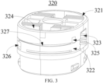
- FIG. 3 is a schematic structural diagram of the atomization base 320 according to an embodiment of this application.
- the atomization base 320 has a top surface 321 and a side surface 322.
- An atomization cavity 323 and a liquid flowing channel 324 are formed inside the atomization base 320.
- the liquid flowing channel 324 extends through the top surface 321 and is in communication with the atomization cavity 323.
- the liquid flowing channel 324 is in communication with the liquid reservoir 311.
- the aerosol-generation substrate stored in the liquid reservoir 311 may flow toward the atomization cavity 323 through the liquid flowing channel 324.
- the atomization core 330 may be arranged inside the atomization cavity 232. After the aerosol-generation substrate in the liquid reservoir 311 flows into the atomization cavity 323 through the liquid flowing channel 324, the aerosol-generation substrate comes into contact with a surface of the atomization core 330, and is atomized on the surface of the atomization core 330 to generate aerosols. The aerosols may flow out through the atomization channel 312 above the atomization core 330.
- the seal member 340 may be arranged between the cartridge tube 310 and the atomization base 320, and is configured to seal gaps between the liquid flowing channel 324 and the liquid reservoir 311 and between the atomization base 320 and the cartridge tube 310. Specifically, the seal member 340 may be wrapped around the top surface 321 and at least part of the side surface 322 of the atomization base 320, with only an opening being retained at the liquid flowing channel 324. In this way, an aerosol-generation substrate leakage from the liquid reservoir 311 can be avoided.
- the atomization base 320 further has an air inlet 325 and an air outlet 326.
- the air inlet 325 and the air outlet 326 are provided on the side surface 322 of the atomization base 320.
- the air inlet 325 is provided at a height lower than that of the top surface 321 of the atomization base 320.
- the air inlet 325 and the air outlet 326 are in communication with each other through an air inlet channel 327.
- the air inlet 325 is in communication with the liquid flowing channel 324.
- the air outlet 326 is in communication with the atomization cavity 323.
- the air inlet 325 and the air outlet 326 may extend through the side surface 322 of the atomization base 320, thereby achieving communication with external air.
- the air inlet channel 327 may be configured to equilibrate the pressure inside the liquid reservoir 311.
- a height difference exists between the air inlet 325 and the air outlet 326, which can facilitate air exchange.
- the air inlet 325 may be provided at a height higher than a height at which the air outlet 326 is provided.
- the air inlet 325 may be provided at a height between the top surface 321 and the atomization cavity 323 of the atomization base 320.
- the air inlet 325 may be provided at a height lower than the height at which the air outlet 326 is provided. Specific heights may be set based on structures of different atomization bases 320, which are not limited herein.
- the air inlet 325 and the air outlet 326 are not limited in this embodiment of this application.
- the air inlet and the air outlet may be in a shape of a circular hole or a square hole, or may be in an irregular shape. Specific shapes may be set based on an actual situation. In this embodiment of this application, a description is provided by using an example in which the air inlet 325 and the air outlet 326 are in the shape of a circular hole.
- the diameters of the air inlet 325 and the air outlet 326 may be set to a range of 0.5 mm to 1 mm. Excessively small diameters of the air inlet 325 and the air outlet 326 may lead to an excessively narrow air inlet channel 327, which impedes air exchange of the liquid reservoir 311. Excessively large diameters of the air inlet 325 and the air outlet 326 may lead to a risk of a liquid leakage.
- the electronic atomization device 1 further includes a seal plug 40.
- the seal plug 40 is configured to be embedded into an end of the atomization channel 312 away from the atomization core 330.
- the seal plug 40 may be configured to seal the atomization channel 312.
- the user may embed the seal plug 40 into the atomization channel 312, to avoid impact of dust accumulation in the atomization channel 312 on subsequent user experience.
- a specific connection manner between the seal plug 40 and the atomization channel 312 is not limited in this implementation of this application.
- the connection manner may be interference fit or engagement.
- the connection manner may be specifically selected based on an actual situation.
- the air inlet 325 in communication with the liquid flowing channel 324 and the air outlet 326 in communication with the atomization channel 312 are both provided on the side surface 322 of the atomization base 320
- the air inlet channel 327 in communication with the air inlet 325 and the air outlet 326 is provided on the side surface 322 of the atomization base 320
- the air inlet 325 and the air outlet 326 are provided at the heights lower than the height of the top surface 321 of the atomization base 320, to perform exchange between airflows inside and outside the atomization base 320 on the side surface 322 of the atomization base 320.
- the aerosol-generation substrate does not flow into the atomization cavity 323 during transportation of the atomizer 30, which avoids an aerosol-generation substrate leakage for the atomizer 30 during transportation, thereby avoiding an aerosol-generation substrate leakage during transportation of the electronic atomization device 1 to which the atomizer 30 is applied.
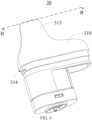
- FIG. 4 is a schematic structural diagram of an atomizer 30 according to an embodiment of this application.
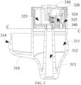
- FIG. 5 is a cross-sectional view along a line B-B in FIG. 4 .
- the atomizer 30 may include a cartridge tube 310, an atomization base 320, an atomization core 330, and a seal member 340.
- a liquid reservoir 311 and an atomization channel 312 may be formed inside the cartridge tube 310.
- the liquid reservoir 311 may be configured to accommodate an aerosol-generation substrate.
- An end of the atomization channel 312 is in communication with the atomization core 330, and an other end is in communication with outside.
- the atomization core 330 may be arranged inside the atomization base 320. Aerosols generated after the atomization core 330 heats and atomizes the aerosol-generation substrate may be transferred to outside of the atomizer 30 through the atomization channel 312 for inhalation by a user.
- the liquid reservoir 311 is arranged around the atomization channel 312.
- FIG. 6 is a schematic structural diagram of another atomization base 320 according to an embodiment of this application.
- a plurality of air outlets 326 may be provided.
- the plurality of air outlets 326 are provided on a side surface 322 of the atomization base 320 at intervals.
- Each air outlet 326 is in communication with the air inlet 325 through one air inlet channel 327.
- a plurality of air inlet channels 327 may be provided for air exchange, which can further improve air exchange efficiency in the liquid reservoir 311, and increase a fault tolerance of the air inlet channels 327.
- the electronic atomization device 1 can still be used normally.
- a plurality of air inlets 325 may be provided.
- the plurality of air inlets 325 are provided on the side surface 322 of the atomization base 320 at intervals. Each air inlet 325 is in communication with the air outlet 326 through one air inlet channel 327.
- a plurality of air inlets 325, a plurality of air outlets 326, and a plurality of air inlet channels 327 may be provided.
- the air inlets 325 and the air outlets may be in communication with each other through the same air inlet channel 327 or through a plurality of air inlet channels 327, which is not limited herein.
- the plurality of air outlets 326 may be provided at the same height, and the height is lower than that of a top surface 321 of the atomization base 320. In this way, the air outlets 326 may be configured to perform air exchange simultaneously, thereby further improving the air exchange efficiency in the liquid reservoir 311.
- the plurality of air outlets 325 may alternatively be provided at different heights on the side surface 322 of the atomization base 320, and the heights of all of the air inlets 325 are lower than that of the top surface 321 of the atomization base 320.
- only one air inlet 325 and one air outlet 326 may be provided, and a plurality of air inlet channels 327 with different paths may be provided between the air inlet 325 and the air outlet 326.
- the air exchange efficiency in the liquid reservoir 311 can be improved, and the fault tolerance of the air inlet channels 327 can be improved.
- the electronic atomization device 1 can still be used normally.
- a specific structure of the air inlet channel 327 is not limited in this embodiment of this application.
- the air inlet channel may have a structure of a straight line or similar to a straight line shown in FIG. 3 , or may have a structure of one or more bent lines shown in FIG. 6 .
- a specific structure may be set based on an actual situation.
- the atomization core 330 may be arranged at an intersection of the liquid flowing channel 324 and the atomization cavity 323.
- the atomization cavity 323 is in communication with the atomization channel 312.
- the aerosol-generation substrate in the liquid reservoir 311 may flow toward the atomization cavity 323 through the liquid flowing channel 324, and come into contact with the atomization core 330.
- the atomization core 330 may heat and atomize the aerosol-generation substrate to generate aerosols.
- the seal member 340 may be arranged between the cartridge tube 310 and the atomization base 320, and is configured to seal gaps between the liquid flowing channel 324 and the liquid reservoir 311 and between the atomization base 320 and the cartridge tube 310. Specifically, the seal member 340 may be wrapped around the top surface 321 and at least part of the side surface 322 of the atomization base 320, with only an opening being retained at the liquid flowing channel 324. In this way, an aerosol-generation substrate leakage from the liquid reservoir 311 can be avoided.
- the air inlet channel 327 includes a groove 3211 provided on the side surface 322, and the groove 3211 may be mated with the seal member 340 to form a channel. In this way, production difficulty of the air inlet channel 327 can be reduced.
- the groove 3211 is a transition section 3211a.
- the depth of the transition section 3211a is arranged to gradually change, and the depth of the transition section 3211a is less than the depth of another part of the groove 3211.
- the depth of the transition section 3211a may be in a range of 0.05 mm to 0.3 mm
- the depth of the part of the groove 3211 other than the transition section 3211a may be in a range of 0.3 mm to 0.6 mm.
- a description is provided by using an example in which the depth of the transition section 3211a is in a range of 0.1 mm to 0.2 mm and the depth of the part of the groove 3211 other than the transition section 3211a is 0.5 mm.
- the aerosol-generation substrate Due to the small depth of the transition section 3211a, the aerosol-generation substrate has a larger surface tension when flowing to the transition section 3211a than flowing to the part of the groove 3211 other than the transition section 3211a. Molecules of the aerosol-generation substrate interact with each other, which results in a protrusion on a surface of the aerosol-generation substrate. Therefore, the aerosol-generation substrate cannot smoothly pass through the transition section 3211a. In other words, the aerosol-generation substrate cannot further flow when flowing to the transition section 3211a through the air inlet 325. Therefore, the aerosol-generation substrate does not leak through the air inlet channel 327.
- air may enter the liquid reservoir 311 through the air inlet channel 327, which maintains a pressure value of the liquid reservoir 311 within a relatively stable range, thereby facilitating atomization of the aerosol-generation substrate by the electronic atomization device 1.
- a specific position of the transition section 3211a is not limited in this embodiment of this application.
- the transition section 3211a may be arranged closer to the air inlet 325, or the transition section 3211a may be arranged closer to the air outlet 326.
- a specific position may be set based on an actual situation.
- a principle description of the electronic atomization device 1 provided in the embodiments of this application is as follows:
- FIG. 5 a usual state of the atomizer 30 is shown in FIG. 5 .
- the atomizer 30 is inverted.
- the aerosol-generation substrate in the liquid reservoir 311 does not fully fill the entire liquid reservoir 311, and instead, a gap is retained.
- a liquid level of the aerosol-generation substrate in the liquid reservoir 311 is usually flush with or slightly higher than a line C-C in the figure.
- the air inlet 325, the air outlet 326, and air inlet channel 327 are all provided on the side surface 322 of the atomization base 320, and the air inlet 325 and the air outlet 326 are provided at the heights lower than the height of the top surface 321 of the atomization base 320. Therefore, the air inlet 325 and the air outlet 326 are not immersed in the aerosol-generation substrate, which avoids an aerosol-generation substrate leakage.
- the air inlet 325 in communication with the liquid flowing channel 324 and the air outlet 326 in communication with the atomization channel 312 are both provided on the side surface 322 of the atomization base 320
- the air inlet channel 327 in communication with the air inlet 325 and the air outlet 326 is provided on the side surface 322 of the atomization base 320
- the air inlet 325 and the air outlet 326 are provided at the heights lower than the height of the top surface 321 of the atomization base 320, to perform exchange between airflows inside and outside the atomization base 320 on the side surface 322 of the atomization base 320.
- the aerosol-generation substrate does not flow into the atomization cavity 323 during transportation of the atomizer 30, which avoids an aerosol-generation substrate leakage for the atomizer 30 during transportation, thereby avoiding an aerosol-generation substrate leakage during transportation of the electronic atomization device 1 to which the atomizer 30 is applied.
Landscapes
- Containers And Packaging Bodies Having A Special Means To Remove Contents (AREA)
- Nozzles (AREA)
- Disinfection, Sterilisation Or Deodorisation Of Air (AREA)
Abstract
This application relates to an atomization base, an atomizer, and an electronic atomization device. The atomization base has a top surface and a side surface, an atomization cavity and a liquid flowing channel are formed inside the atomization base, and the liquid flowing channel extends through the top surface and is in communication with the atomization cavity. The atomization base further has an air inlet and an air outlet. The air inlet in communication with the liquid flowing channel and the air outlet in communication with the atomization cavity are both provided on the side surface of the atomization base, the air inlet channel in communication with the air inlet and the air outlet is provided on the side surface of the atomization base, and the air inlet and the air outlet are provided at heights lower than the height of the top surface of the atomization base.
Description
- This application relates to the field of electronic atomization technologies, and in particular, to an atomization base, an atomizer, and an electronic atomization device.
- An electronic atomization device generally includes an atomizer and a power supply assembly. The atomizer is configured to store and atomize an aerosol-generation substrate, and the power supply assembly is configured to provide electric energy for operation of the atomizer.
- An atomizer is generally composed of an atomization base and an atomization core. The atomization core is usually arranged inside the atomization base and is configured to heat and atomize an aerosol-generation substrate in a liquid reservoir. To equilibrate air pressure in the liquid reservoir, in a structure of a conventional atomizer, a liquid stop groove is usually provided on a top of an atomization base, and a seal member is arranged between the atomization base and a liquid reservoir, to perform air exchange through a gap between the atomization base and the seal member, in which case the aerosol-generation substrate easily comes into contact with an atomization cavity of the atomization base. Since the atomizer usually needs to be inverted during transportation, the aerosol-generation substrate may flow into the atomization cavity, resulting in an aerosol-generation substrate leakage.
- Based on the above, it is necessary to provide an atomization base, an atomizer, and an electronic atomization device for the above problem, to at least partially ameliorate the above problem.
- According to an aspect, this application provides an atomization base. The atomization base has a top surface and a side surface, an atomization cavity and a liquid flowing channel are formed inside the atomization base, and the liquid flowing channel extends through the top surface and is in communication with the atomization cavity. The atomization base further has an air inlet and an air outlet, the air inlet is in communication with the liquid flowing channel, the air outlet is in communication with the atomization cavity, the air inlet and the air outlet are provided at heights lower than the height of the top surface, and the air inlet and the air outlet are in communication with an air inlet channel.
- In an embodiment, the air inlet and the air outlet are provided on the side surface of the atomization base, and a height difference exists between the air inlet and the air outlet.
- In an embodiment, the air inlet channel includes a groove provided on the side surface.
- In an embodiment, at least part of the groove is a transition section, and the depth of the transition section is arranged to gradually change.
- In an embodiment, the depth of the transition section is in a range of 0.05 mm to 0.3 mm, and the depth of a part of the groove other than the transition section is in a range of 0.3 mm to 0.6 mm.
- In an embodiment, a plurality of air outlets are provided, the plurality of air outlets are provided on the atomization base at intervals, and each air outlet is in communication with the air inlet through one air inlet channel.
- In an embodiment, the plurality of air outlets are provided at a same height.
- According to another aspect, this application further provides an atomizer. The atomizer includes a cartridge tube, the above atomization base, an atomization core, and a seal member. A liquid reservoir and an atomization channel are formed inside the cartridge tube, and the liquid reservoir is arranged around the atomization channel. The liquid flowing channel is in communication with the liquid reservoir, and the atomization cavity is in communication with the atomization channel. The atomization core is arranged at an intersection of the liquid flowing channel and the atomization cavity. The seal member is arranged between the cartridge tube and the atomization base, and is configured to seal a gap between the liquid flowing channel and the liquid reservoir.
- According to still another aspect, an embodiment of this application further provides an electronic atomization device. The electronic atomization device includes a shell, a power supply device, and the above atomizer. The shell is connected to the atomizer, and the shell surrounds the atomizer, to form a power supply compartment inside the shell. The power supply device is arranged in the power supply compartment, and is electrically connected to the atomizer.
- In an embodiment, the electronic atomization device further includes a seal plug. The seal plug is configured to be embedded into an end of the atomization channel away from the atomization core.
- In the above atomization base, the air inlet in communication with the liquid flowing channel and the air outlet in communication with the atomization cavity are both provided on the side surface of the atomization base, the air inlet channel in communication with the air inlet and the air outlet is provided on the side surface of the atomization base, and the air inlet and the air outlet are provided at heights lower than the height of the top surface of the atomization base, to perform exchange between airflows inside and outside the atomization base on the side surface of the atomization base. Since two ends of the air inlet channel are both located on the side surface of the atomization base rather than on an end portion, after the atomization base is fitted to the atomizer, an aerosol-generation substrate does not flow into the atomization cavity during transportation of the atomizer, which avoids an aerosol-generation substrate leakage for the atomizer during transportation.
-
-
FIG. 1 is a schematic structural diagram of an electronic atomization device according to an embodiment of this application. -
FIG. 2 is a cross-sectional view along a line A-A inFIG. 1 . -
FIG. 3 is a schematic structural diagram of an atomization base according to an embodiment of this application. -
FIG. 4 is a schematic structural diagram of another atomizer according to an embodiment of this application. -
FIG. 5 is a cross-sectional view along a line B-B inFIG. 4 . -
FIG. 6 is a schematic structural diagram of another atomization base according to an embodiment of this application. - Reference numerals:
Electronic atomization device 1, Shell 10,Power supply compartment 110,First engagement portion 120,Power supply device 20, Atomizer 30, Cartridgetube 310,Liquid reservoir 311, Atomizationchannel 312, Suctionnozzle 313,Second engagement portion 314,Atomization base 320,Top surface 321, Groove 3211,Transition section 3211a,Side surface 322,Atomization cavity 323, Liquid flowingchannel 324,Air inlet 325,Air outlet 326,Air inlet channel 327,Atomization core 330, Sealmember 340,Seal plug 40. - To make the above objectives, features, and advantages of this application more apparent and comprehensible, specific implementations of this application are described in detail below with reference to drawings. In the following description, many specific details are described for thorough understanding of this application. However, this application may be implemented in many other manners different from those described herein. A person skilled in the art may make similar improvements without departing from the connotation of this application. Therefore, this application is not limited to the specific embodiments disclosed below.
- In the description of this application, it should be understood that orientation or position relationships indicated by terms such as "center", "longitudinal", "transverse", "length", "width", "thickness", "up", "down", "front", "rear", "left", "right", "vertical", "horizontal", "top", "bottom", "inside", "outside", "clockwise", "anticlockwise", "axial direction", "radial direction", and "circumferential direction" are based on orientation or position relationships shown in the drawings, and are merely used for ease and brevity of description of this application, rather than indicating or implying that the mentioned device or element needs to have a particular orientation or be constructed and operated in a particular orientation. Therefore, such terms should not be construed as a limitation on this application.
- In addition, terms "first" and "second" are merely used for description, and cannot be understood as indicating or implying relative importance or implying a quantity of indicated technical features. Therefore, features defined with "first" and "second" may explicitly or implicitly include at least one of the features. In description of this application, "a plurality of" means at least two, such as two or three, unless otherwise definitely and specifically defined.
- In this application, unless otherwise explicitly specified or defined, terms such as "mount", "connect", "connection", and "fix" should be understood in a broad sense. For example, the connection may be a fixed connection, a detachable connection, or an integral connection, or may be a mechanical connection or an electrical connection, or may be a direct connection, an indirect connection through an intermediate medium, internal communication between two elements, or an interaction relationship between two elements. A person of ordinary skill in the art may understand specific meanings of the above terms in this application based on a specific case.
- In this application, unless otherwise explicitly specified and defined, a first feature being "on" or "under" a second feature may mean that the first feature is in direct contact with the second feature, or the first feature is in indirect contact with the second feature by using an intermediate medium. In addition, the first feature being "above", "over", or "on" the second feature may mean that the first feature is directly or obliquely above the second feature, or merely indicate that the first feature is at a higher horizontal position than the second feature. The first feature being "below", "under", and "beneath" the second feature may mean that the first feature is directly or obliquely below the second feature, or merely indicate that the first feature is at a lower horizontal position than the second feature.
- It should be noted that, when an element is referred to as "being fixed to" or "being arranged on" another element, the element may be directly located on the another element, or an intermediate element may exist. When an element is considered to be "connected to" another element, the element may be directly connected to the another element, or an intermediate element may exist. The terms "vertical", "horizontal", "up", "down", "left", "right", and similar expressions used in this specification are merely used for illustration and do not indicate a unique implementation.
- An electronic atomization device provided in the embodiments of this application is configured to heat an aerosol-generation substrate to generate aerosols for use by a user. A heating manner may be convection, conduction, radiation, or a combination thereof. The aerosol-generation substrate may be in a form of a liquid, a gel, a paste, a solid, or the like. When the aerosol-generation substrate is a solid, the aerosol-generation substrate may be a solid in a fragmented, granular, powdery, grainy, strip, or flake form. The aerosol-generation substrate includes but is not limited to materials used for medical treatment, health maintenance, fitness, and beauty. For example, the aerosol-generation substrate is a medicinal solution or an e-liquid. Alternatively, the aerosol-generation substrate is a plant material, for example, a root, a stem, a leave, a flower, a bud, or a seed of a plant.
- An electronic atomization device generally includes an atomizer and a power supply assembly. The atomizer is configured to store and atomize an aerosol-generation substrate, and the power supply assembly is configured to provide electric energy for operation of the atomizer.
- An atomizer is generally composed of an atomization base and an atomization core. The atomization core is usually arranged inside the atomization base and is configured to heat and atomize an aerosol-generation substrate in a liquid reservoir. To equilibrate air pressure in the liquid reservoir, in a structure of a conventional atomizer, a liquid stop groove is usually provided on a top of an atomization base, and a seal member is arranged between the atomization base and a liquid reservoir, to perform air exchange through a gap between the atomization base and the seal member, in which case the aerosol-generation substrate easily comes into contact with an atomization cavity of the atomization base. Since the atomizer usually needs to be inverted during transportation, the aerosol-generation substrate may flow into the atomization cavity, resulting in an aerosol-generation substrate leakage.
- Based on the above problem, an embodiment of this application provides an
electronic atomization device 1. Referring toFIG. 1 andFIG. 2 together,FIG. 1 is a schematic structural diagram of theelectronic atomization device 1 according to an embodiment of this application.FIG. 2 is a cross-sectional view along a line A-A inFIG. 1 . - The
electronic atomization device 1 provided in this embodiment of this application may include ashell 10, apower supply device 20, and anatomizer 30. - The
shell 10 is connected to theatomizer 30. After theshell 10 is connected to theatomizer 30, apower supply compartment 110 is formed inside the shell. Thepower supply device 20 is arranged in thepower supply compartment 110. A specific connection manner between theshell 10 and theatomizer 30 is not limited in this embodiment of this application. For example, the connection manner may be engagement or interference fit. In this embodiment of this application, a description is provided by using an example in which theshell 10 is engaged with theatomizer 30. - Specifically, in this embodiment, the
shell 10 may include afirst engagement portion 120, and theatomizer 30 may include asecond engagement portion 314 mated with thefirst engagement portion 120. Thefirst engagement portion 120 may be an engagement groove, and thesecond engagement portion 314 may be an engagement block. In some other implementations, thefirst engagement portion 120 may be an engagement block, and thesecond engagement portion 314 may be an engagement groove, which is not limited herein. Theshell 10 may be engaged with theatomizer 30 through thefirst engagement portion 120 and thesecond engagement portion 314. - The
power supply device 20 is electrically connected to theatomizer 30. Thepower supply device 20 is configured to provide electric energy to theatomizer 30. A specific form of thepower supply device 20 is not limited in this embodiment of this application. For example, the power supply device may be a rechargeable battery, or may be a disposable battery. The specific form may be selected based on an actual situation. - The
atomizer 30 is configured to heat and atomize the aerosol-generation substrate. Specifically, still referring toFIG. 2 , in this embodiment, the atomizer may include acartridge tube 310, anatomization base 320, anatomization core 330, and aseal member 340. - A
liquid reservoir 311 and anatomization channel 312 may be formed inside thecartridge tube 310. Theliquid reservoir 311 may be configured to accommodate an aerosol-generation substrate. An end of theatomization channel 312 is in communication with theatomization core 330, and an other end is in communication with outside. Theatomization core 330 may be arranged inside theatomization base 320. Aerosols generated after theatomization core 330 heats and atomizes the aerosol-generation substrate may be transferred to outside of theatomizer 30 through theatomization channel 312 for inhalation by a user. Theliquid reservoir 311 is arranged around theatomization channel 312. - In an implementation, an end of the
cartridge tube 310 may be arranged to protrude to form asuction nozzle 313 for inhalation by the user. A specific shape of thesuction nozzle 313 is not limited in this embodiment of this application. For example, the suction nozzle may be in a cylindrical shape or a flat shape. The specific shape may be selected based on an actual situation. - Referring to
FIG. 2 andFIG. 3 together,FIG. 3 is a schematic structural diagram of theatomization base 320 according to an embodiment of this application. In this embodiment, theatomization base 320 has atop surface 321 and aside surface 322. Anatomization cavity 323 and aliquid flowing channel 324 are formed inside theatomization base 320. Theliquid flowing channel 324 extends through thetop surface 321 and is in communication with theatomization cavity 323. Theliquid flowing channel 324 is in communication with theliquid reservoir 311. The aerosol-generation substrate stored in theliquid reservoir 311 may flow toward theatomization cavity 323 through theliquid flowing channel 324. - In this embodiment, the
atomization core 330 may be arranged inside the atomization cavity 232. After the aerosol-generation substrate in theliquid reservoir 311 flows into theatomization cavity 323 through theliquid flowing channel 324, the aerosol-generation substrate comes into contact with a surface of theatomization core 330, and is atomized on the surface of theatomization core 330 to generate aerosols. The aerosols may flow out through theatomization channel 312 above theatomization core 330. - The
seal member 340 may be arranged between thecartridge tube 310 and theatomization base 320, and is configured to seal gaps between the liquid flowingchannel 324 and theliquid reservoir 311 and between theatomization base 320 and thecartridge tube 310. Specifically, theseal member 340 may be wrapped around thetop surface 321 and at least part of theside surface 322 of theatomization base 320, with only an opening being retained at theliquid flowing channel 324. In this way, an aerosol-generation substrate leakage from theliquid reservoir 311 can be avoided. - Further, still referring to
FIG. 3 , theatomization base 320 further has anair inlet 325 and anair outlet 326. Theair inlet 325 and theair outlet 326 are provided on theside surface 322 of theatomization base 320. Theair inlet 325 is provided at a height lower than that of thetop surface 321 of theatomization base 320. Theair inlet 325 and theair outlet 326 are in communication with each other through anair inlet channel 327. Theair inlet 325 is in communication with theliquid flowing channel 324. Theair outlet 326 is in communication with theatomization cavity 323. Theair inlet 325 and theair outlet 326 may extend through theside surface 322 of theatomization base 320, thereby achieving communication with external air. Theair inlet channel 327 may be configured to equilibrate the pressure inside theliquid reservoir 311. - Further, in some implementations, a height difference exists between the
air inlet 325 and theair outlet 326, which can facilitate air exchange. Specifically, in this embodiment, theair inlet 325 may be provided at a height higher than a height at which theair outlet 326 is provided. In this case, theair inlet 325 may be provided at a height between thetop surface 321 and theatomization cavity 323 of theatomization base 320. In some other implementations, theair inlet 325 may be provided at a height lower than the height at which theair outlet 326 is provided. Specific heights may be set based on structures ofdifferent atomization bases 320, which are not limited herein. - It should be noted that, specific shapes of the
air inlet 325 and theair outlet 326 are not limited in this embodiment of this application. For example, the air inlet and the air outlet may be in a shape of a circular hole or a square hole, or may be in an irregular shape. Specific shapes may be set based on an actual situation. In this embodiment of this application, a description is provided by using an example in which theair inlet 325 and theair outlet 326 are in the shape of a circular hole. - In addition, in consideration of manufacturability and productibility, the diameters of the
air inlet 325 and theair outlet 326 may be set to a range of 0.5 mm to 1 mm. Excessively small diameters of theair inlet 325 and theair outlet 326 may lead to an excessively narrowair inlet channel 327, which impedes air exchange of theliquid reservoir 311. Excessively large diameters of theair inlet 325 and theair outlet 326 may lead to a risk of a liquid leakage. - Referring to
FIG. 1 andFIG. 2 again, in some implementations, theelectronic atomization device 1 further includes aseal plug 40. The seal plug 40 is configured to be embedded into an end of theatomization channel 312 away from theatomization core 330. The seal plug 40 may be configured to seal theatomization channel 312. When the user does not use theelectronic atomization device 1, the user may embed theseal plug 40 into theatomization channel 312, to avoid impact of dust accumulation in theatomization channel 312 on subsequent user experience. It should be noted that, a specific connection manner between theseal plug 40 and theatomization channel 312 is not limited in this implementation of this application. For example, the connection manner may be interference fit or engagement. The connection manner may be specifically selected based on an actual situation. - In the
atomization base 320 provided in this embodiment of this application, theair inlet 325 in communication with theliquid flowing channel 324 and theair outlet 326 in communication with theatomization channel 312 are both provided on theside surface 322 of theatomization base 320, theair inlet channel 327 in communication with theair inlet 325 and theair outlet 326 is provided on theside surface 322 of theatomization base 320, and theair inlet 325 and theair outlet 326 are provided at the heights lower than the height of thetop surface 321 of theatomization base 320, to perform exchange between airflows inside and outside theatomization base 320 on theside surface 322 of theatomization base 320. Since two ends of theair inlet channel 327 are both located on theside surface 322 of theatomization base 320 rather than on an end portion, after theatomization base 320 is fitted to theatomizer 30, the aerosol-generation substrate does not flow into theatomization cavity 323 during transportation of theatomizer 30, which avoids an aerosol-generation substrate leakage for theatomizer 30 during transportation, thereby avoiding an aerosol-generation substrate leakage during transportation of theelectronic atomization device 1 to which theatomizer 30 is applied. - In addition, an embodiment of this application provides another atomizer. Referring to
FIG. 4 andFIG. 5 together,FIG. 4 is a schematic structural diagram of anatomizer 30 according to an embodiment of this application.FIG. 5 is a cross-sectional view along a line B-B inFIG. 4 . - In this embodiment, the
atomizer 30 may include acartridge tube 310, anatomization base 320, anatomization core 330, and aseal member 340. - A
liquid reservoir 311 and anatomization channel 312 may be formed inside thecartridge tube 310. Theliquid reservoir 311 may be configured to accommodate an aerosol-generation substrate. An end of theatomization channel 312 is in communication with theatomization core 330, and an other end is in communication with outside. Theatomization core 330 may be arranged inside theatomization base 320. Aerosols generated after theatomization core 330 heats and atomizes the aerosol-generation substrate may be transferred to outside of theatomizer 30 through theatomization channel 312 for inhalation by a user. Theliquid reservoir 311 is arranged around theatomization channel 312. - Further, referring to
FIG. 5 andFIG. 6, FIG. 6 is a schematic structural diagram of anotheratomization base 320 according to an embodiment of this application. It should be noted that, in this implementation, a plurality ofair outlets 326 may be provided. The plurality ofair outlets 326 are provided on aside surface 322 of theatomization base 320 at intervals. Eachair outlet 326 is in communication with theair inlet 325 through oneair inlet channel 327. In other words, in this implementation, a plurality ofair inlet channels 327 may be provided for air exchange, which can further improve air exchange efficiency in theliquid reservoir 311, and increase a fault tolerance of theair inlet channels 327. When anair inlet channel 327 is blocked, theelectronic atomization device 1 can still be used normally. - It should be noted that, in some other implementations, a plurality of
air inlets 325 may be provided. The plurality ofair inlets 325 are provided on theside surface 322 of theatomization base 320 at intervals. Eachair inlet 325 is in communication with theair outlet 326 through oneair inlet channel 327. Similarly, in some other implementations, a plurality ofair inlets 325, a plurality ofair outlets 326, and a plurality ofair inlet channels 327 may be provided. The air inlets 325 and the air outlets may be in communication with each other through the sameair inlet channel 327 or through a plurality ofair inlet channels 327, which is not limited herein. - Specifically, the plurality of
air outlets 326 may be provided at the same height, and the height is lower than that of atop surface 321 of theatomization base 320. In this way, theair outlets 326 may be configured to perform air exchange simultaneously, thereby further improving the air exchange efficiency in theliquid reservoir 311. The plurality ofair outlets 325 may alternatively be provided at different heights on theside surface 322 of theatomization base 320, and the heights of all of theair inlets 325 are lower than that of thetop surface 321 of theatomization base 320. - It may be understood that, in some other implementations, only one
air inlet 325 and oneair outlet 326 may be provided, and a plurality ofair inlet channels 327 with different paths may be provided between theair inlet 325 and theair outlet 326. In this way, the air exchange efficiency in theliquid reservoir 311 can be improved, and the fault tolerance of theair inlet channels 327 can be improved. When anair inlet channel 327 is blocked, theelectronic atomization device 1 can still be used normally. - It should be noted that, a specific structure of the
air inlet channel 327 is not limited in this embodiment of this application. For example, the air inlet channel may have a structure of a straight line or similar to a straight line shown inFIG. 3 , or may have a structure of one or more bent lines shown inFIG. 6 . A specific structure may be set based on an actual situation. - Still referring to
FIG. 4 , in this embodiment, theatomization core 330 may be arranged at an intersection of theliquid flowing channel 324 and theatomization cavity 323. Theatomization cavity 323 is in communication with theatomization channel 312. The aerosol-generation substrate in theliquid reservoir 311 may flow toward theatomization cavity 323 through theliquid flowing channel 324, and come into contact with theatomization core 330. Theatomization core 330 may heat and atomize the aerosol-generation substrate to generate aerosols. - Referring to
FIG. 5 again, theseal member 340 may be arranged between thecartridge tube 310 and theatomization base 320, and is configured to seal gaps between the liquid flowingchannel 324 and theliquid reservoir 311 and between theatomization base 320 and thecartridge tube 310. Specifically, theseal member 340 may be wrapped around thetop surface 321 and at least part of theside surface 322 of theatomization base 320, with only an opening being retained at theliquid flowing channel 324. In this way, an aerosol-generation substrate leakage from theliquid reservoir 311 can be avoided. - Referring to
FIG. 6 again, in an implementation, theair inlet channel 327 includes agroove 3211 provided on theside surface 322, and thegroove 3211 may be mated with theseal member 340 to form a channel. In this way, production difficulty of theair inlet channel 327 can be reduced. - Further, at least part of the
groove 3211 is atransition section 3211a. The depth of thetransition section 3211a is arranged to gradually change, and the depth of thetransition section 3211a is less than the depth of another part of thegroove 3211. For example, the depth of thetransition section 3211a may be in a range of 0.05 mm to 0.3 mm, and the depth of the part of thegroove 3211 other than thetransition section 3211a may be in a range of 0.3 mm to 0.6 mm. In this embodiment of this application, a description is provided by using an example in which the depth of thetransition section 3211a is in a range of 0.1 mm to 0.2 mm and the depth of the part of thegroove 3211 other than thetransition section 3211a is 0.5 mm. Due to the small depth of thetransition section 3211a, the aerosol-generation substrate has a larger surface tension when flowing to thetransition section 3211a than flowing to the part of thegroove 3211 other than thetransition section 3211a. Molecules of the aerosol-generation substrate interact with each other, which results in a protrusion on a surface of the aerosol-generation substrate. Therefore, the aerosol-generation substrate cannot smoothly pass through thetransition section 3211a. In other words, the aerosol-generation substrate cannot further flow when flowing to thetransition section 3211a through theair inlet 325. Therefore, the aerosol-generation substrate does not leak through theair inlet channel 327. In addition, during inhalation of the user, air may enter theliquid reservoir 311 through theair inlet channel 327, which maintains a pressure value of theliquid reservoir 311 within a relatively stable range, thereby facilitating atomization of the aerosol-generation substrate by theelectronic atomization device 1. - It should be noted that, a specific position of the
transition section 3211a is not limited in this embodiment of this application. For example, thetransition section 3211a may be arranged closer to theair inlet 325, or thetransition section 3211a may be arranged closer to theair outlet 326. A specific position may be set based on an actual situation. - A principle description of the
electronic atomization device 1 provided in the embodiments of this application is as follows: - Referring to
FIG. 5 again, during transportation of the electronic atomization device provided in the embodiments of this application, a usual state of theatomizer 30 is shown inFIG. 5 . Theatomizer 30 is inverted. During loading, the aerosol-generation substrate in theliquid reservoir 311 does not fully fill the entireliquid reservoir 311, and instead, a gap is retained. After theatomizer 30 is inverted, a liquid level of the aerosol-generation substrate in theliquid reservoir 311 is usually flush with or slightly higher than a line C-C in the figure. In theelectronic atomization device 1 provided in the embodiments of this application, theair inlet 325, theair outlet 326, andair inlet channel 327 are all provided on theside surface 322 of theatomization base 320, and theair inlet 325 and theair outlet 326 are provided at the heights lower than the height of thetop surface 321 of theatomization base 320. Therefore, theair inlet 325 and theair outlet 326 are not immersed in the aerosol-generation substrate, which avoids an aerosol-generation substrate leakage. - In summary, in the
atomization base 320 provided in this embodiment of this application, theair inlet 325 in communication with theliquid flowing channel 324 and theair outlet 326 in communication with theatomization channel 312 are both provided on theside surface 322 of theatomization base 320, theair inlet channel 327 in communication with theair inlet 325 and theair outlet 326 is provided on theside surface 322 of theatomization base 320, and theair inlet 325 and theair outlet 326 are provided at the heights lower than the height of thetop surface 321 of theatomization base 320, to perform exchange between airflows inside and outside theatomization base 320 on theside surface 322 of theatomization base 320. Since two ends of theair inlet channel 327 are both located on theside surface 322 of theatomization base 320 rather than on an end portion, after theatomization base 320 is fitted to theatomizer 30, the aerosol-generation substrate does not flow into theatomization cavity 323 during transportation of theatomizer 30, which avoids an aerosol-generation substrate leakage for theatomizer 30 during transportation, thereby avoiding an aerosol-generation substrate leakage during transportation of theelectronic atomization device 1 to which theatomizer 30 is applied. - The technical features of the above embodiments may be combined in different manners. To make the description concise, not all possible combinations of the technical features in the above embodiments are described. However, the combinations of these technical features are considered to fall within the scope recorded in this specification provided that no conflict exists. In addition, another implementation may be derived from the above embodiments, so that structural and logical substitutions and changes may be made without departing from the scope of the present disclosure.
- The above embodiments describe only some implementations of this application, which are described specifically and in detail, but cannot be construed as a limitation on the patent scope of this application. It should be noted that a person of ordinary skill in the art may make some transformations and improvements without departing from the idea of this application. These transformations and improvements belong to the protection scope of this application. Therefore, the protection scope of the patent of this application shall be subject to the appended claims.
Claims (10)
- An atomization base, comprising:a top surface;a side surface;an air inlet; andat least one air outlet,wherein an atomization cavity and a liquid flowing channel are formed inside the atomization base, the liquid flowing channel extends through the top surface and is in communication with the atomization cavity,wherein the air inlet is in communication with the liquid flowing channel,wherein the at least one air outlet is in communication with the atomization cavity,wherein the air inlet and the at least one air outlet are provided at heights lower than a height of the top surface, andwherein the air inlet and the at least one air outlet are in communication with at least one air inlet channel.
- The atomization base of claim 1, wherein the air inlet and the at least one air outlet are provided on the side surface of the atomization base, and
wherein a height difference exists between the air inlet and the at least one air outlet. - The atomization base of claim 1, wherein the at least one air inlet channel comprises a groove provided on the side surface.
- The atomization base of claim 3, wherein at least part of the groove is a transition section, and a depth of the transition section gradually changes.
- The atomization base of claim 4, wherein the depth of the transition section is in a range of 0.05 mm to 0.3 mm, and
wherein a depth of a part of the groove other than the transition section is in a range of 0.3 mm to 0.6 mm. - The atomization base of claim 1, wherein the at least one air outlet comprises a plurality of air outlets provided on the atomization base at intervals, and
wherein each air outlet of the plurality of air outlets is in communication with the air inlet through one air inlet channel of the at least one air inlet channel. - The atomization base of claim 6, wherein the plurality of air outlets are provided at a same height.
- The atomization base of claim 1, wherein the at least one air inlet channel comprises a plurality of air inlet channels, and each air inlet channel of the plurality of air inlet channels is in communication with the air inlet and the at least one air outlet.
- An atomizer, comprising:a cartridge tube, a liquid reservoir and an atomization channel being formed inside the cartridge tube;the atomization base of any of claims 1 to 8, the liquid flowing channel thereof being in communication with the liquid reservoir, and the atomization cavity thereof being in communication with the atomization channel;an atomization core arranged at an intersection of the liquid flowing channel and the atomization cavity; anda seal member arranged between the cartridge tube and the atomization base and configured to seal a gap between the liquid flowing channel and the liquid reservoir.
- An electronic atomization device, comprising:a shell;a power supply device; andthe atomizer of claim 9,wherein the shell is connected to the atomizer,wherein a power supply compartment is formed inside the shell after the shell is connected to the atomizer, andwherein the power supply device is arranged in the power supply compartment, and is electrically connected to the atomizer.
Applications Claiming Priority (1)
| Application Number | Priority Date | Filing Date | Title |
|---|---|---|---|
| CN202323088615.8U CN221510965U (en) | 2023-11-15 | 2023-11-15 | Atomizer seat, atomizer and electronic atomizer device |
Publications (1)
| Publication Number | Publication Date |
|---|---|
| EP4570095A1 true EP4570095A1 (en) | 2025-06-18 |
Family
ID=92202744
Family Applications (1)
| Application Number | Title | Priority Date | Filing Date |
|---|---|---|---|
| EP24211710.9A Pending EP4570095A1 (en) | 2023-11-15 | 2024-11-08 | Atomization base, atomizer, and electronic atomization device |
Country Status (3)
| Country | Link |
|---|---|
| US (1) | US20250151802A1 (en) |
| EP (1) | EP4570095A1 (en) |
| CN (1) | CN221510965U (en) |
Families Citing this family (1)
| Publication number | Priority date | Publication date | Assignee | Title |
|---|---|---|---|---|
| USD1105590S1 (en) * | 2024-02-18 | 2025-12-09 | Shenzhen Smoore Technology Limited | Electronic atomizing device |
Citations (2)
| Publication number | Priority date | Publication date | Assignee | Title |
|---|---|---|---|---|
| WO2022040935A1 (en) * | 2020-08-25 | 2022-03-03 | 深圳麦克韦尔科技有限公司 | Electronic atomizing device |
| WO2023124213A1 (en) * | 2021-12-30 | 2023-07-06 | 江门摩尔科技有限公司 | Atomizer and electronic atomization device |
-
2023
- 2023-11-15 CN CN202323088615.8U patent/CN221510965U/en active Active
-
2024
- 2024-11-08 EP EP24211710.9A patent/EP4570095A1/en active Pending
- 2024-11-14 US US18/947,763 patent/US20250151802A1/en active Pending
Patent Citations (2)
| Publication number | Priority date | Publication date | Assignee | Title |
|---|---|---|---|---|
| WO2022040935A1 (en) * | 2020-08-25 | 2022-03-03 | 深圳麦克韦尔科技有限公司 | Electronic atomizing device |
| WO2023124213A1 (en) * | 2021-12-30 | 2023-07-06 | 江门摩尔科技有限公司 | Atomizer and electronic atomization device |
Also Published As
| Publication number | Publication date |
|---|---|
| US20250151802A1 (en) | 2025-05-15 |
| CN221510965U (en) | 2024-08-13 |
Similar Documents
| Publication | Publication Date | Title |
|---|---|---|
| US12042601B2 (en) | Electronic atomization device and atomization assembly | |
| US20220218038A1 (en) | Electronic atomization device and atomizer thereof | |
| US12022861B2 (en) | Electronic cigarette and atomizer thereof with heating assembly | |
| CN112120298B (en) | Electronic atomization device and atomizer thereof | |
| CN111109678B (en) | Electronic atomization device, atomizer and atomization assembly thereof | |
| US20250151802A1 (en) | Atomization base, atomizer, and electronic atomization device | |
| CN114259091B (en) | Atomization structural parts, atomizers and aerosol generating devices | |
| CN218303457U (en) | Atomizing support, atomizer and electron atomizing device | |
| CN217487672U (en) | Electronic atomization device and atomizer and atomization core thereof | |
| CN213819852U (en) | Electronic atomization device and atomizer thereof | |
| CN217446666U (en) | Ceramic heating body, atomizer and aerosol generating device | |
| CN218354673U (en) | Atomization assembly, atomizer and electronic atomization device | |
| WO2023087892A1 (en) | Electronic atomization device and atomizer thereof | |
| CN218418422U (en) | Atomizing core structure, atomizer and electronic atomization device | |
| US12357030B2 (en) | Electronic vaporization device providing sufficient air flow | |
| CN215775515U (en) | Electronic atomization device, atomizer and atomization assembly thereof | |
| US20240074509A1 (en) | Electronic vaporization device and vaporizer thereof | |
| CN218650319U (en) | Atomizing core and aerosol generating device | |
| CN218303429U (en) | Sealing member, atomization component, atomizer and electronic atomization device | |
| WO2022040866A1 (en) | Electronic atomization apparatus and atomizer thereof | |
| US20240074503A1 (en) | Electronic vaporization device and vaporizer thereof | |
| CN217906291U (en) | Atomization structure and electronic atomization device | |
| CN216875007U (en) | Atomizer and electronic atomization device | |
| CN217184807U (en) | Nebulizer, atomizing core unit and aerosol generating device | |
| CN217089582U (en) | Electronic atomization device, atomizer and atomization assembly thereof |
Legal Events
| Date | Code | Title | Description |
|---|---|---|---|
| PUAI | Public reference made under article 153(3) epc to a published international application that has entered the european phase |
Free format text: ORIGINAL CODE: 0009012 |
|
| STAA | Information on the status of an ep patent application or granted ep patent |
Free format text: STATUS: THE APPLICATION HAS BEEN PUBLISHED |
|
| AK | Designated contracting states |
Kind code of ref document: A1 Designated state(s): AL AT BE BG CH CY CZ DE DK EE ES FI FR GB GR HR HU IE IS IT LI LT LU LV MC ME MK MT NL NO PL PT RO RS SE SI SK SM TR |
|
| STAA | Information on the status of an ep patent application or granted ep patent |
Free format text: STATUS: REQUEST FOR EXAMINATION WAS MADE |
|
| 17P | Request for examination filed |
Effective date: 20251120 |