EP4570089A1 - Aerosol provision device - Google Patents
Aerosol provision device Download PDFInfo
- Publication number
- EP4570089A1 EP4570089A1 EP24154020.2A EP24154020A EP4570089A1 EP 4570089 A1 EP4570089 A1 EP 4570089A1 EP 24154020 A EP24154020 A EP 24154020A EP 4570089 A1 EP4570089 A1 EP 4570089A1
- Authority
- EP
- European Patent Office
- Prior art keywords
- aerosol
- aerosol provision
- provision device
- peripheral wall
- receptacle
- Prior art date
- Legal status (The legal status is an assumption and is not a legal conclusion. Google has not performed a legal analysis and makes no representation as to the accuracy of the status listed.)
- Pending
Links
Images




Classifications
-
- A—HUMAN NECESSITIES
- A24—TOBACCO; CIGARS; CIGARETTES; SIMULATED SMOKING DEVICES; SMOKERS' REQUISITES
- A24F—SMOKERS' REQUISITES; MATCH BOXES; SIMULATED SMOKING DEVICES
- A24F40/00—Electrically operated smoking devices; Component parts thereof; Manufacture thereof; Maintenance or testing thereof; Charging means specially adapted therefor
- A24F40/40—Constructional details, e.g. connection of cartridges and battery parts
-
- A—HUMAN NECESSITIES
- A24—TOBACCO; CIGARS; CIGARETTES; SIMULATED SMOKING DEVICES; SMOKERS' REQUISITES
- A24F—SMOKERS' REQUISITES; MATCH BOXES; SIMULATED SMOKING DEVICES
- A24F40/00—Electrically operated smoking devices; Component parts thereof; Manufacture thereof; Maintenance or testing thereof; Charging means specially adapted therefor
- A24F40/10—Devices using liquid inhalable precursors
-
- A—HUMAN NECESSITIES
- A24—TOBACCO; CIGARS; CIGARETTES; SIMULATED SMOKING DEVICES; SMOKERS' REQUISITES
- A24F—SMOKERS' REQUISITES; MATCH BOXES; SIMULATED SMOKING DEVICES
- A24F40/00—Electrically operated smoking devices; Component parts thereof; Manufacture thereof; Maintenance or testing thereof; Charging means specially adapted therefor
- A24F40/20—Devices using solid inhalable precursors
-
- A—HUMAN NECESSITIES
- A24—TOBACCO; CIGARS; CIGARETTES; SIMULATED SMOKING DEVICES; SMOKERS' REQUISITES
- A24F—SMOKERS' REQUISITES; MATCH BOXES; SIMULATED SMOKING DEVICES
- A24F40/00—Electrically operated smoking devices; Component parts thereof; Manufacture thereof; Maintenance or testing thereof; Charging means specially adapted therefor
- A24F40/40—Constructional details, e.g. connection of cartridges and battery parts
- A24F40/46—Shape or structure of electric heating means
Definitions
- the present disclosure relates to the field of providing aerosols.
- the present disclosure relates to an aerosol provision device.
- the present disclosure also relates to an aerosol provision system and a method of generating an aerosol.
- Smoking items such as cigarettes, cigars and the like traditionally burn tobacco during use, producing tobacco smoke. Efforts are being made to create alternatives to such items. In this regard, it may be envisaged in particular to heat, but not burn, a suitable material to release certain compounds, particularly in an inhalable aerosol.
- a suitable material may or may not contain tobacco and may or may not contain nicotine.
- Such a material may, e.g., be provided in a cylindrical unit or, more generally, an article comprising an aerosol generating material.
- an aerosol provision device for generating aerosol from aerosol generating material, the aerosol provision device comprising:
- the aerosol provision device may comprise a heater.
- the heater may define at least a part of the receptacle.
- the heater may be a resistive heating heater.
- the heater may comprise a resistive heating element in the housing.
- the resistive heating element may comprise a resistive heating coil.
- the heater may be an inductive heating heater.
- the heater may comprise an inductive heating element in the housing.
- the inductive heating element may comprise an inductive heating coil.
- the heater may protrude into the receptacle.
- the peripheral wall of the receptacle may at least partially extend around the heater as well.
- the receptacle may define at least a portion of a chamber, and the heater may be exposed to the chamber.
- the inner surface of the peripheral wall of the receptacle may be provided as or associated with a reflecting surface configured to reflect electromagnetic radiation towards the article.
- the structured surface may extend over at least 50%, at least 75% or at least 90% of the outer surface.
- the structuring elements of the structured surface may include one or more meandering channels.
- the structuring elements of the structured surface may include labyrinthic features.
- the structuring elements may be provided as joint or disjoint elements or groups of elements.
- the structuring elements of the structured surface may comprise joint or disjoint indentations or protrusions.
- the structuring elements of the structured surface may have at least one of a circular, rectangular, triangular, polygonal and irregular shape in a vertical projection to the structured surface.
- the structuring elements of the structured surface may taper in a depth direction vertical to the structured surface.
- a depth of the structuring elements of the structured surface may be in a range of 0.05 to 0.5 mm or 0.2 mm.
- a material of the peripheral wall may be a plastics material, particularly an at least partly heat-resistant plastics material.
- a void space at least partly surrounding the peripheral wall may be provided in the device.
- a system comprising a device according to any possible embodiment as mentioned above and below and an article including aerosol generating material is also provided.
- a method of generating an aerosol including:
- aerosol-generating material is a material that is capable of generating aerosol, for example when heated, irradiated or energized in any other way.
- Aerosol-generating material may, for example, be in the form of a solid, liquid or gel which may or may not contain an active substance and/or flavourants.
- Aerosol-generating material may include any plant based material, such as tobacco-containing material and may, for example, include one or more of tobacco, tobacco derivatives, expanded tobacco, reconstituted tobacco or tobacco substitutes. Aerosol-generating material also may include other, non-tobacco, products, which, depending on the product, may or may not contain nicotine.
- Aerosol-generating material may for example be in the form of a solid, a liquid, a gel, a wax or the like. Aerosol-generating material may for example also be a combination or a blend of materials. Aerosol-generating material may also be known as "smokable material".
- the aerosol-generating material may comprise a binder and an aerosol former.
- an active and/or filler may also be present.
- a solvent such as water, is also present and one or more other components of the aerosol-generating material may or may not be soluble in the solvent.
- the aerosol-generating material is substantially free from botanical material. In some embodiments, the aerosol-generating material is substantially tobacco free.
- the aerosol-generating material may comprise or be an "amorphous solid".
- the amorphous solid may be a "monolithic solid".
- the amorphous solid may be a dried gel.
- the amorphous solid is a solid material that may retain some fluid, such as liquid, within it.
- the aerosol-generating material may, for example, comprise from about 50wt%, 60wt% or 70wt% of amorphous solid, to about 90wt%, 95wt% or 100wt% of amorphous solid.
- the aerosol-generating material may comprise an aerosol-generating film.
- the aerosol-generating film may comprise or be a sheet, which may optionally be shredded to form a shredded sheet.
- the aerosol-generating sheet or shredded sheet may be substantially tobacco free.
- a "non-combustible" aerosol provision system is one where a constituent aerosol-generating material of the aerosol provision system (or component thereof) is not combusted or burned in order to facilitate delivery of at least one substance to a user.
- the delivery system is a non-combustible aerosol provision system, such as a powered non-combustible aerosol provision system.
- the non-combustible aerosol provision system is an electronic cigarette, also known as a vaping device or electronic nicotine delivery system (END), although it is noted that the presence of nicotine in the aerosol-generating material is not a requirement.
- END electronic nicotine delivery system
- the non-combustible aerosol provision system is an aerosol-generating material heating system, also known as a heat-not-burn system.
- a heat-not-burn system is a tobacco heating system.
- the non-combustible aerosol provision system is a hybrid system to generate aerosol using a combination of aerosol-generating materials, one or a plurality of which may be heated.
- Each of the aerosol-generating materials may be, for example, in the form of a solid, liquid or gel and may or may not contain nicotine.
- the hybrid system comprises a liquid or gel aerosol-generating material and a solid aerosol-generating material.
- the solid aerosol-generating material may comprise, for example, tobacco or a non-tobacco product.
- the non-combustible aerosol provision system may comprise a non-combustible aerosol provision device and a consumable for use with the non-combustible aerosol provision device.
- the disclosure relates to consumables comprising aerosol-generating material and configured to be used with non-combustible aerosol provision devices. These consumables are sometimes referred to as articles throughout the disclosure.
- the non-combustible aerosol provision system such as a non-combustible aerosol provision device thereof, may comprise a power source and a controller.
- the power source may, for example, be an electric power source or an exothermic power source.
- the exothermic power source comprises a carbon substrate which may be energised so as to distribute power in the form of heat to an aerosol-generating material or to a heat transfer material in proximity to the exothermic power source.
- the non-combustible aerosol provision system may comprise an area for receiving the consumable, an aerosol generator, an aerosol generation area, a housing, a mouthpiece, a filter and/or an aerosol-modifying agent.
- the consumable for use with the non-combustible aerosol provision device may comprise aerosol-generating material, an aerosol-generating material storage area, an aerosol-generating material transfer component, an aerosol generator, an aerosol generation area, a housing, a wrapper, a filter, a mouthpiece, and/or an aerosol-modifying agent.
- An aerosol generating device can receive an article comprising aerosol generating material for heating.
- An "article” in this context is a component that includes or contains in use the aerosol generating material, which is heated to volatilise the aerosol generating material, and optionally other components in use.
- a user may insert the article into the aerosol generating device before it is heated to produce an aerosol, which the user subsequently inhales.
- the article may be, for example, of a predetermined or specific size that is configured to be placed within a heating chamber of the device which is sized to receive the article.
- Figures 1A to 1C show perspective views of an aerosol provision device 100 in three different operational configurations, wherein an "operational configuration" may result from at least one of certain components of device 100 being operated by a user or an article being inserted into the device 100.
- the aerosol provision device 100 is configured to generate aerosol from an aerosol generating article, which is not shown in Figures 1A and 1B and which is shown and referred to with reference numeral 200 in Figure 1C .
- the aerosol provision device 100 is an elongate structure, extending along a longitudinal axis.
- the aerosol provision device 100 has a proximal end 101, which will be closest to the user (e.g. the user's mouth) when in use by the user to inhale the aerosol generated by the aerosol provision device 100, as well as a distal end 102 which will be furthest from the user when in use.
- the proximal end 101 may also be referred to as the "mouth end” or "top end”.
- the proximal end 101 of the aerosol provision device 100 is formed by a subunit commonly referred to as an extractor 110, whose function is also described below.
- the aerosol generating article 200 may be inserted, in use, into the aerosol provision device 100.
- the aerosol provision device 100 or more precisely the extractor 110, comprises an opening to a receptacle 103, as shown in Figure 1B , into which the aerosol generating article 200 may be inserted, and which is not fully shown for reasons of clarity.
- the aerosol generating article 200 may form part of the aerosol provision device 100, or the aerosol provision device 100 and the article 200 may be understood as parts of an aerosol generating system as referred to with reference numeral 1000 in Figure 1C .
- the aerosol provision device 100 also accordingly defines a proximal direction, which is directed towards the user when in use. Further, the aerosol provision device 100 also likewise defines a distal direction, which is directed away from the user when in use.
- proximal and distal as applied to features of the device 100 will be described by reference to the relative positioning of such features with respect to each other in a proximal-distal direction along a longitudinal axis which is not shown for reasons of conciseness.
- the device 100 includes a slidable lid unit 150.
- the slidable lid unit 150 may be closed so as to cover the opening to the receptacle 103 of the aerosol provision device 100 as shown in Figure 1A , and therefore restricts access to the receptacle 103.
- the slidable lid unit 150 may be held in certain positions by magnets associated with the lid unit 150 and/or a body of the device 100 beneath the lid unit 150. As shown in Figures 1B and 1C , the lid unit 150 may be opened to provide or restrict access to the opening to the receptacle 103.
- One or more user-operable control elements 104 such as buttons, sliders or the like which can be used to operate the aerosol provision device 100, may be provided on a side of the aerosol provision device 100.
- Figures 2A and 2B show the device 100 already shown in Figures 1A to 1C in a side view, wherein Figure 2A illustrates an assembled state and Figure 2B shows a disassembled or drawn-apart state.
- the device 100 comprises, apart from the extractor 110 already shown before, a further subunit commonly referred to as a main body 120 with structures surrounding a part of the extractor 110, including in particular control electronics and one or more batteries, and a housing unit 130.
- an aerosol When in use, an aerosol is withdrawn from the article 200 by a user via his or her mouth and inhaled, but in between puffs, aerosol will continue to form and will be emitted from the article 200.
- Some of the aerosol and other moisture may condense in the device 100 on some, particularly colder, surfaces, generating unwanted moisture and sticky residues, as further explained below.
- This phenomenon but also the surface temperature of the device 100, is a critical item for customer experience.
- a root cause for high surface temperature is that a heating isolation may not be sufficient, and a root cause for aerosol condensation may be a lack of condensation retaining features on the device 100 or that a condensation spread trace may be too small.
- Embodiments as disclosed herein are provided to at overcome these disadvantages, providing both an improved insulation and a condensate retention in certain embodiments. Embodiments as disclosed herein therefore provide an improved user experience as an outer surface of a device 100 may stay cooler and less condensate may form.
- Figures 3A and 3B show certain parts of the device 100 and the article 200 essentially shown in the previous Figures already, but in a non-inventive configuration, in a drawn-apart view ( Figure 3A ) and in an assembled view ( Figure 3B ).
- the extractor 110 which is shown here again, forms part of a removal mechanism which is used to aid extraction of the article 200 by pulling the article off a heater 125, or, more specifically, a pin-shaped part 125a thereof in a reliable way.
- the pin-shaped element 125a protrudes from the main body 120 shown before into a chamber in which the receptacle 103 of the extractor 110 is received.
- the receptacle 103 is surrounded, and defined, by a peripheral wall 111.
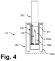
- Figure 4 shows a simplified schematic view of certain parts of a device 100 as already illustrated before.
- Figure 4 in particular is not drawn to scale and particularly certain distances and/or void spaces are exaggerated to demonstrate certain aspects for better understanding of embodiments disclosed herein.
- the main body 120 which may be surrounded, as before, by a housing 130, is shown in dashed outline only, and it may comprise any suitable structures 120a surrounding the extractor 110 which is also shown in a strongly simplified view.
- Embodiments disclosed herein may help to reduce or eliminate condensate formation or draining off of condensate formed, and may also provide further advantages in connection with heat conduction to the outer housing of the device 100.
- a root cause for condensation may be a lack of condensation retaining features on an outer surface of the peripheral wall 111 or a too small condensation surface, and embodiments disclosed herein are intended to increase this surface.
- Figures 5A and 5B show enlarged views of extractor 110 in a view corresponding to Figures 2A and 2B (see Figure 5A ) and in a view orthogonal thereto (see Figure 5B ) according to an embodiment.
- the extractor 110 comprises the receptacle 103 configured for receiving at least a portion of the article, into which the heater 125 or the pin-shaped structure element 125a thereof protrudes in assembled state, as already shown several times before.
- the peripheral wall enclosing and defining the receptacle 103 is again indicated with 111 in Figures 5A and 5B .
- a part or subregion 113 of an outer surface of the peripheral wall 111 is provided as a structured surface, wherein, in this specific example, meandering grooves 114 are provided as structuring elements.
- the "outer surface” is to be understood to be the surface of the peripheral wall facing away from the article 200 when the latter is inserted into the receptacle 103 and to further structures of the base unit 120.
- a meandering groove 114 may, however, only be one of a plurality of structuring elements which may be provided in certain embodiments.
- Structuring elements may be selected on the basis of specific requirements and may be provided in a part of the enclosing structure, particularly in a bottom region where condensate may particularly form and/or heating structures are arranged. They may be prepared in the form of joint or disjoint structures or groups of structures of any type conceivable.
- Providing the structuring elements serves the purpose of generating an air gap between the peripheral wall 111 and its surrounding structures, and also of forming retention regions for condensate which therefore cannot run off and reach the outside of the device 100 and the environment or sensitive parts within the base unit 120.
- the structuring elements of the structured surface of the peripheral wall 111 may comprise disjoint indentations or protrusions as illustrated in these Figures in only a limited number of examples, including indentations with, in a projection to the surface, a quadratic, a pentagonal, a trigonal, a rectangular, a circular or a hexagonal shape.
Landscapes
- Resistance Heating (AREA)
- Containers And Packaging Bodies Having A Special Means To Remove Contents (AREA)
Abstract
Aspects disclosed herein include an aerosol provision device configured to heat at least part of an article comprising aerosol generating material comprises a receptacle configured for receiving at least a portion of the article, the receptacle comprising a peripheral wall. An outer surface of the peripheral wall is at least partly provided as a structured surface comprising structuring elements.
Description
- The present disclosure relates to the field of providing aerosols. In particular, the present disclosure relates to an aerosol provision device. The present disclosure also relates to an aerosol provision system and a method of generating an aerosol.
- Smoking items such as cigarettes, cigars and the like traditionally burn tobacco during use, producing tobacco smoke. Efforts are being made to create alternatives to such items. In this regard, it may be envisaged in particular to heat, but not burn, a suitable material to release certain compounds, particularly in an inhalable aerosol. A suitable material may or may not contain tobacco and may or may not contain nicotine. Such a material may, e.g., be provided in a cylindrical unit or, more generally, an article comprising an aerosol generating material.
- According to an aspect, there is provided an aerosol provision device for generating aerosol from aerosol generating material, the aerosol provision device comprising:
- a receptacle for receiving at least a portion of an article comprising the aerosol generating material, the receptacle comprising a peripheral wall;
- wherein an outer surface of the peripheral wall is at least partly provided as a structured surface comprising structuring elements.
- In an embodiment of any of the above, the aerosol provision device may comprise a heater. The heater may define at least a part of the receptacle.
- In an embodiment of any of the above, the heater may be a resistive heating heater. The heater may comprise a resistive heating element in the housing. The resistive heating element may comprise a resistive heating coil.
- In an embodiment of any of the above, the heater may be an inductive heating heater. The heater may comprise an inductive heating element in the housing. The inductive heating element may comprise an inductive heating coil.
- In an embodiment of any of the above, the heater may protrude into the receptacle. The peripheral wall of the receptacle may at least partially extend around the heater as well. The receptacle may define at least a portion of a chamber, and the heater may be exposed to the chamber.
- In an embodiment of any of the above, the inner surface of the peripheral wall of the receptacle may be provided as or associated with a reflecting surface configured to reflect electromagnetic radiation towards the article.
- In an embodiment of any of the above, the structured surface may extend over at least 50%, at least 75% or at least 90% of the outer surface.
- In an embodiment of any of the above, the structuring elements of the structured surface may include one or more meandering channels.
- In an embodiment of any of the above, the structuring elements of the structured surface may include labyrinthic features.
- In an embodiment of any of the above, the structuring elements may be provided as joint or disjoint elements or groups of elements.
- In an embodiment of any of the above, the structuring elements of the structured surface may comprise joint or disjoint indentations or protrusions.
- In an embodiment of any of the above, the structuring elements of the structured surface may have at least one of a circular, rectangular, triangular, polygonal and irregular shape in a vertical projection to the structured surface.
- In an embodiment of any of the above, the structuring elements of the structured surface may taper in a depth direction vertical to the structured surface.
- In an embodiment of any of the above, a depth of the structuring elements of the structured surface may be in a range of 0.05 to 0.5 mm or 0.2 mm.
- In an embodiment of any of the above, a material of the peripheral wall may be a plastics material, particularly an at least partly heat-resistant plastics material.
- In an embodiment of any of the above, a void space at least partly surrounding the peripheral wall may be provided in the device.
- According to a further aspect, a system comprising a device according to any possible embodiment as mentioned above and below and an article including aerosol generating material is also provided.
- According to a further aspect, there is provided a method of generating an aerosol, including:
- providing an aerosol provision device as indicated above; and
- operating the aerosol provision device.
- Various embodiments will now be described, by way of example only, and with reference to the accompanying drawings, in which:
-
Figure 1A to 1C show perspective views of an aerosol provision device in three different operational configurations; -
Figures 2A and 2B show subunits of an aerosol provision device as shown inFigures 1A to 1C in an assembled and in a drawn-apart view; -
Figures 3A and3B show an enlarged drawn-apart and assembled view of certain parts of an aerosol provision device; -
Figure 4 shows a simplified schematic view of certain parts of an aerosol provision device as shown inFigures 3A and3B ; -
Figures 5A and5B show enlarged partial views of the aerosol provision device as shown in the previous Figures; and -
Figures 6A to 6F show a schematic views of structuring elements usable in certain configurations provided herein. - As used herein, the term "aerosol-generating material" is a material that is capable of generating aerosol, for example when heated, irradiated or energized in any other way. Aerosol-generating material may, for example, be in the form of a solid, liquid or gel which may or may not contain an active substance and/or flavourants. Aerosol-generating material may include any plant based material, such as tobacco-containing material and may, for example, include one or more of tobacco, tobacco derivatives, expanded tobacco, reconstituted tobacco or tobacco substitutes. Aerosol-generating material also may include other, non-tobacco, products, which, depending on the product, may or may not contain nicotine. Aerosol-generating material may for example be in the form of a solid, a liquid, a gel, a wax or the like. Aerosol-generating material may for example also be a combination or a blend of materials. Aerosol-generating material may also be known as "smokable material".
- The aerosol-generating material may comprise a binder and an aerosol former. Optionally, an active and/or filler may also be present. Optionally, a solvent, such as water, is also present and one or more other components of the aerosol-generating material may or may not be soluble in the solvent. In some embodiments, the aerosol-generating material is substantially free from botanical material. In some embodiments, the aerosol-generating material is substantially tobacco free.
- The aerosol-generating material may comprise or be an "amorphous solid". The amorphous solid may be a "monolithic solid". In some embodiments, the amorphous solid may be a dried gel. The amorphous solid is a solid material that may retain some fluid, such as liquid, within it. In some embodiments, the aerosol-generating material may, for example, comprise from about 50wt%, 60wt% or 70wt% of amorphous solid, to about 90wt%, 95wt% or 100wt% of amorphous solid.
- The aerosol-generating material may comprise an aerosol-generating film. The aerosol-generating film may comprise or be a sheet, which may optionally be shredded to form a shredded sheet. The aerosol-generating sheet or shredded sheet may be substantially tobacco free.
- According to the present disclosure, a "non-combustible" aerosol provision system is one where a constituent aerosol-generating material of the aerosol provision system (or component thereof) is not combusted or burned in order to facilitate delivery of at least one substance to a user.
- In some embodiments, the delivery system is a non-combustible aerosol provision system, such as a powered non-combustible aerosol provision system.
- In some embodiments, the non-combustible aerosol provision system is an electronic cigarette, also known as a vaping device or electronic nicotine delivery system (END), although it is noted that the presence of nicotine in the aerosol-generating material is not a requirement.
- In some embodiments, the non-combustible aerosol provision system is an aerosol-generating material heating system, also known as a heat-not-burn system. An example of such a system is a tobacco heating system.
- In some embodiments, the non-combustible aerosol provision system is a hybrid system to generate aerosol using a combination of aerosol-generating materials, one or a plurality of which may be heated. Each of the aerosol-generating materials may be, for example, in the form of a solid, liquid or gel and may or may not contain nicotine. In some embodiments, the hybrid system comprises a liquid or gel aerosol-generating material and a solid aerosol-generating material. The solid aerosol-generating material may comprise, for example, tobacco or a non-tobacco product.
- Typically, the non-combustible aerosol provision system may comprise a non-combustible aerosol provision device and a consumable for use with the non-combustible aerosol provision device.
- In some embodiments, the disclosure relates to consumables comprising aerosol-generating material and configured to be used with non-combustible aerosol provision devices. These consumables are sometimes referred to as articles throughout the disclosure.
- In some embodiments, the non-combustible aerosol provision system, such as a non-combustible aerosol provision device thereof, may comprise a power source and a controller. The power source may, for example, be an electric power source or an exothermic power source. In some embodiments, the exothermic power source comprises a carbon substrate which may be energised so as to distribute power in the form of heat to an aerosol-generating material or to a heat transfer material in proximity to the exothermic power source.
- In some embodiments, the non-combustible aerosol provision system may comprise an area for receiving the consumable, an aerosol generator, an aerosol generation area, a housing, a mouthpiece, a filter and/or an aerosol-modifying agent.
- In some embodiments, the consumable for use with the non-combustible aerosol provision device may comprise aerosol-generating material, an aerosol-generating material storage area, an aerosol-generating material transfer component, an aerosol generator, an aerosol generation area, a housing, a wrapper, a filter, a mouthpiece, and/or an aerosol-modifying agent.
- An aerosol generating device can receive an article comprising aerosol generating material for heating. An "article" in this context is a component that includes or contains in use the aerosol generating material, which is heated to volatilise the aerosol generating material, and optionally other components in use. A user may insert the article into the aerosol generating device before it is heated to produce an aerosol, which the user subsequently inhales. The article may be, for example, of a predetermined or specific size that is configured to be placed within a heating chamber of the device which is sized to receive the article.
-
Figures 1A to 1C show perspective views of anaerosol provision device 100 in three different operational configurations, wherein an "operational configuration" may result from at least one of certain components ofdevice 100 being operated by a user or an article being inserted into thedevice 100. - In
Figures 1A to 1C , like reference numerals indicate the same, essentially the same, functionally identical, or similar components and will be described together hereinbelow. Repeated explanations are omitted for reasons of conciseness. - The
aerosol provision device 100 is configured to generate aerosol from an aerosol generating article, which is not shown inFigures 1A and1B and which is shown and referred to withreference numeral 200 inFigure 1C . - The
aerosol provision device 100 is an elongate structure, extending along a longitudinal axis. Theaerosol provision device 100 has aproximal end 101, which will be closest to the user (e.g. the user's mouth) when in use by the user to inhale the aerosol generated by theaerosol provision device 100, as well as adistal end 102 which will be furthest from the user when in use. Theproximal end 101 may also be referred to as the "mouth end" or "top end". As further explained below, theproximal end 101 of theaerosol provision device 100 is formed by a subunit commonly referred to as anextractor 110, whose function is also described below. - The
aerosol generating article 200 may be inserted, in use, into theaerosol provision device 100. For this purpose, theaerosol provision device 100, or more precisely theextractor 110, comprises an opening to areceptacle 103, as shown inFigure 1B , into which theaerosol generating article 200 may be inserted, and which is not fully shown for reasons of clarity. In certain embodiments, theaerosol generating article 200 may form part of theaerosol provision device 100, or theaerosol provision device 100 and thearticle 200 may be understood as parts of an aerosol generating system as referred to withreference numeral 1000 inFigure 1C . - The
aerosol provision device 100 also accordingly defines a proximal direction, which is directed towards the user when in use. Further, theaerosol provision device 100 also likewise defines a distal direction, which is directed away from the user when in use. The terms proximal and distal as applied to features of thedevice 100 will be described by reference to the relative positioning of such features with respect to each other in a proximal-distal direction along a longitudinal axis which is not shown for reasons of conciseness. - The
device 100 includes aslidable lid unit 150. When theaerosol provision device 100 is not in use, theslidable lid unit 150 may be closed so as to cover the opening to thereceptacle 103 of theaerosol provision device 100 as shown inFigure 1A , and therefore restricts access to thereceptacle 103. Theslidable lid unit 150 may be held in certain positions by magnets associated with thelid unit 150 and/or a body of thedevice 100 beneath thelid unit 150. As shown inFigures 1B and1C , thelid unit 150 may be opened to provide or restrict access to the opening to thereceptacle 103. - One or more user-
operable control elements 104, such as buttons, sliders or the like which can be used to operate theaerosol provision device 100, may be provided on a side of theaerosol provision device 100. -
Figures 2A and 2B show thedevice 100 already shown inFigures 1A to 1C in a side view, whereinFigure 2A illustrates an assembled state andFigure 2B shows a disassembled or drawn-apart state. As can be seen fromFigure 2B in particular, thedevice 100 comprises, apart from theextractor 110 already shown before, a further subunit commonly referred to as amain body 120 with structures surrounding a part of theextractor 110, including in particular control electronics and one or more batteries, and ahousing unit 130. - When in use, an aerosol is withdrawn from the
article 200 by a user via his or her mouth and inhaled, but in between puffs, aerosol will continue to form and will be emitted from thearticle 200. Some of the aerosol and other moisture may condense in thedevice 100 on some, particularly colder, surfaces, generating unwanted moisture and sticky residues, as further explained below. This phenomenon, but also the surface temperature of thedevice 100, is a critical item for customer experience. A root cause for high surface temperature is that a heating isolation may not be sufficient, and a root cause for aerosol condensation may be a lack of condensation retaining features on thedevice 100 or that a condensation spread trace may be too small. - Embodiments as disclosed herein are provided to at overcome these disadvantages, providing both an improved insulation and a condensate retention in certain embodiments. Embodiments as disclosed herein therefore provide an improved user experience as an outer surface of a
device 100 may stay cooler and less condensate may form. -
Figures 3A and3B show certain parts of thedevice 100 and thearticle 200 essentially shown in the previous Figures already, but in a non-inventive configuration, in a drawn-apart view (Figure 3A ) and in an assembled view (Figure 3B ). Theextractor 110, which is shown here again, forms part of a removal mechanism which is used to aid extraction of thearticle 200 by pulling the article off aheater 125, or, more specifically, a pin-shapedpart 125a thereof in a reliable way. The pin-shapedelement 125a protrudes from themain body 120 shown before into a chamber in which thereceptacle 103 of theextractor 110 is received. The pin upstands in theextractor 110 through a hole in the base of the receptacle, as becomes clear in a synoptic view ofFigures 3A and3B . Thereceptacle 103 is surrounded, and defined, by aperipheral wall 111. -
Figure 4 shows a simplified schematic view of certain parts of adevice 100 as already illustrated before.Figure 4 in particular is not drawn to scale and particularly certain distances and/or void spaces are exaggerated to demonstrate certain aspects for better understanding of embodiments disclosed herein. Themain body 120, which may be surrounded, as before, by ahousing 130, is shown in dashed outline only, and it may comprise anysuitable structures 120a surrounding theextractor 110 which is also shown in a strongly simplified view. - As shown in
Figure 4 with a dashed arrow, when an aerosol is withdrawn from thearticle 200 by a user via his or her mouth, a stream of air is generated which first passes along an outer surface of thearticle 200, is then redirected by suitable features towards a distal end of thearticle 200, and passes through an air inlet orheating region 200a of thearticle 200 where it is loaded with aerosol particle. Air may also be present at the outer surface of theperipheral wall 111, i.e. in a gap between the peripheral wall and the surroundingstructures 120a. If this air contains water, this may condense at the outer surface of theperipheral wall 111 and condensate may build up at this outer surface. Formed condensate may drain off, causing an unpleasant user experience and/or damage to internal parts of thedevice 100, such as electronics in thebase unit 120. - Embodiments disclosed herein, which are now discussed with reference to the subsequent Figures, may help to reduce or eliminate condensate formation or draining off of condensate formed, and may also provide further advantages in connection with heat conduction to the outer housing of the
device 100. As recognized by the present inventors, a root cause for condensation may be a lack of condensation retaining features on an outer surface of theperipheral wall 111 or a too small condensation surface, and embodiments disclosed herein are intended to increase this surface. -
Figures 5A and5B show enlarged views ofextractor 110 in a view corresponding toFigures 2A and 2B (seeFigure 5A ) and in a view orthogonal thereto (seeFigure 5B ) according to an embodiment. - The
extractor 110 comprises thereceptacle 103 configured for receiving at least a portion of the article, into which theheater 125 or the pin-shapedstructure element 125a thereof protrudes in assembled state, as already shown several times before. - The peripheral wall enclosing and defining the
receptacle 103 is again indicated with 111 inFigures 5A and5B . A cap covering theproximal part 101 of thedevice 100, as shown before, and which is exposed to a user and the outer surface of thedevice 100, is also part ofextractor 110 in this specific example, but may also be provided as, or being part of, a different subunit of thedevice 100. - As shown in
Figures 5A and5B , a part orsubregion 113 of an outer surface of theperipheral wall 111 is provided as a structured surface, wherein, in this specific example, meanderinggrooves 114 are provided as structuring elements. The "outer surface" is to be understood to be the surface of the peripheral wall facing away from thearticle 200 when the latter is inserted into thereceptacle 103 and to further structures of thebase unit 120. - A meandering
groove 114 may, however, only be one of a plurality of structuring elements which may be provided in certain embodiments. Structuring elements may be selected on the basis of specific requirements and may be provided in a part of the enclosing structure, particularly in a bottom region where condensate may particularly form and/or heating structures are arranged. They may be prepared in the form of joint or disjoint structures or groups of structures of any type conceivable. - Providing the structuring elements serves the purpose of generating an air gap between the
peripheral wall 111 and its surrounding structures, and also of forming retention regions for condensate which therefore cannot run off and reach the outside of thedevice 100 and the environment or sensitive parts within thebase unit 120. - As illustrated in
Figures 6A to 6F , the structuring elements of the structured surface of theperipheral wall 111 may comprise disjoint indentations or protrusions as illustrated in these Figures in only a limited number of examples, including indentations with, in a projection to the surface, a quadratic, a pentagonal, a trigonal, a rectangular, a circular or a hexagonal shape. - While in
Figures 6A to 6F only one kind of structures is shown in each partial Figure, any combination of structural elements may be provided according to embodiments. While inFigures 6A to 6F disjoint structures are shown, they may also provided as joint structures, particularly to generate a combined structure. Any combinations, grouping or the like, of the same or different types of elements may be provided. - The various embodiments described herein are presented only to assist in understanding and teaching the claimed features. These embodiments are provided as a representative sample of embodiments only, and are not exhaustive and/or exclusive. It is to be understood that advantages, embodiments, examples, functions, features, structures, and/or other aspects described herein are not to be considered limitations on the scope of the invention as defined by the claims or limitations on equivalents to the claims, and that other embodiments may be utilised and modifications may be made without departing from the scope of the claimed invention. Various embodiments of the invention may suitably comprise, consist of, or consist essentially of, appropriate combinations of the disclosed elements, components, features, parts, steps, means, etc, other than those specifically described herein. In addition, this disclosure may include other inventions not presently claimed, but which may be claimed in future.
Claims (15)
- An aerosol provision device for generating aerosol from aerosol generating material, the aerosol provision device comprising:a receptacle for receiving at least a portion of an article comprising the aerosol generating material, the receptacle comprising a peripheral wall;wherein an outer surface of the peripheral wall is at least partly provided as a structured surface comprising structuring elements.
- The aerosol provision device of claim 1, comprising a heater.
- The aerosol provision device of claim 2, wherein the heater is a resistive heating heater, and/or wherein the heater comprises a housing and a resistive heating element in the housing, and/or wherein the heater protrudes into the receptacle.
- The aerosol provision device of claim 2 or 3, wherein the peripheral wall of the receptacle at least partially extends around the heater.
- The aerosol provision device of any of claims 2 to 4, wherein the receptacle defines at least a portion of a chamber, and wherein the heater is exposed to the chamber.
- The aerosol provision device of any of claims 1 to 5, wherein an inner surface of the peripheral wall of the receptacle is be provided as or associated with a reflecting surface configured to reflect electromagnetic radiation towards the article.
- The aerosol provision device of any of claims 1 to 6, wherein the structured surface extends over at least 50%, 75% or 90% of the outer surface of the peripheral wall.
- The aerosol provision device of any of claims 1 to 7, wherein the structuring elements are be provided as joint or disjoint elements or groups of elements.
- The device according to any one of claims 1 to 8, wherein the structuring elements of the structured surface include an least one of one or more meandering or bending channels, labyrinthic features and joint or disjoint indentations or protrusions having at least one of a circular, rectangular, triangular, polygonal and irregular shape in a vertical projection to the structured surface.
- The device according to any of claims 1 to 9, wherein the structuring elements of the structured surface taper in a depth direction vertical to the structured surface.
- The device according to any of claims 1 to 10, wherein a depth of the structuring elements of the structured surface is in a range of 0.01 to 0.5 mm.
- The device according to any of claims 1 to 11, wherein a material of the peripheral wall is be a plastics material, particularly a heat-resistant plastics material.
- The device according to any of claims 1 to 12, wherein a void space surrounding the peripheral wall is provided.
- An aerosol provision system comprising a device according to any of claims 1 to 13 and an article including aerosol generating material.
- A method of generating an aerosol, including:providing an aerosol provision device according to any of claims 1 to 14; andoperating the aerosol provision device.
Priority Applications (1)
| Application Number | Priority Date | Filing Date | Title |
|---|---|---|---|
| PCT/EP2024/086090 WO2025125517A1 (en) | 2023-12-13 | 2024-12-12 | Aerosol provision device |
Applications Claiming Priority (1)
| Application Number | Priority Date | Filing Date | Title |
|---|---|---|---|
| CN202311714727.1A CN120130695A (en) | 2023-12-13 | 2023-12-13 | Aerosol supply device |
Publications (1)
| Publication Number | Publication Date |
|---|---|
| EP4570089A1 true EP4570089A1 (en) | 2025-06-18 |
Family
ID=89723090
Family Applications (1)
| Application Number | Title | Priority Date | Filing Date |
|---|---|---|---|
| EP24154020.2A Pending EP4570089A1 (en) | 2023-12-13 | 2024-01-25 | Aerosol provision device |
Country Status (2)
| Country | Link |
|---|---|
| EP (1) | EP4570089A1 (en) |
| CN (1) | CN120130695A (en) |
Citations (6)
| Publication number | Priority date | Publication date | Assignee | Title |
|---|---|---|---|---|
| US5665262A (en) * | 1991-03-11 | 1997-09-09 | Philip Morris Incorporated | Tubular heater for use in an electrical smoking article |
| CN108323821A (en) * | 2018-03-30 | 2018-07-27 | 上海新型烟草制品研究院有限公司 | A kind of holding mechanism and aerosol generating device |
| US20190150508A1 (en) * | 2016-05-13 | 2019-05-23 | British American Tobacco (Investments) Limited | Apparatus for heating smokable material |
| WO2021099423A1 (en) * | 2019-11-18 | 2021-05-27 | Jt International Sa | Aerosol generation device |
| US20220361574A1 (en) * | 2019-09-06 | 2022-11-17 | Jt International Sa | Aerosol Generation Device and Heating Chamber Therefor |
| WO2023117994A1 (en) * | 2021-12-22 | 2023-06-29 | Nicoventures Trading Limited | Aerosol provision device |
-
2023
- 2023-12-13 CN CN202311714727.1A patent/CN120130695A/en active Pending
-
2024
- 2024-01-25 EP EP24154020.2A patent/EP4570089A1/en active Pending
Patent Citations (6)
| Publication number | Priority date | Publication date | Assignee | Title |
|---|---|---|---|---|
| US5665262A (en) * | 1991-03-11 | 1997-09-09 | Philip Morris Incorporated | Tubular heater for use in an electrical smoking article |
| US20190150508A1 (en) * | 2016-05-13 | 2019-05-23 | British American Tobacco (Investments) Limited | Apparatus for heating smokable material |
| CN108323821A (en) * | 2018-03-30 | 2018-07-27 | 上海新型烟草制品研究院有限公司 | A kind of holding mechanism and aerosol generating device |
| US20220361574A1 (en) * | 2019-09-06 | 2022-11-17 | Jt International Sa | Aerosol Generation Device and Heating Chamber Therefor |
| WO2021099423A1 (en) * | 2019-11-18 | 2021-05-27 | Jt International Sa | Aerosol generation device |
| WO2023117994A1 (en) * | 2021-12-22 | 2023-06-29 | Nicoventures Trading Limited | Aerosol provision device |
Also Published As
| Publication number | Publication date |
|---|---|
| CN120130695A (en) | 2025-06-13 |
Similar Documents
| Publication | Publication Date | Title |
|---|---|---|
| US12532912B2 (en) | Apparatus for heating smokable material | |
| CN110313645B (en) | Device with mouthpiece made of high temperature non-toxic material | |
| EP3454681B1 (en) | Apparatus for heating smokable material | |
| JP2023165701A (en) | Device for heating aerosol generating material | |
| EP4262449B1 (en) | Aerosol-generating article comprising dual aerosol generating-substrates | |
| US20250261688A1 (en) | Aerosol Generating Device and Assembly, and Packaging Enabling Easy Grabbing of a Consumable Article | |
| JP2025509493A (en) | Cleaning tool for cleaning the aerosol delivery device | |
| WO2025125517A1 (en) | Aerosol provision device | |
| US20250057215A1 (en) | Aerosol provision device | |
| CN120130695A (en) | Aerosol supply device | |
| US20250072507A1 (en) | Aerosol generating device | |
| EP4570086A1 (en) | Aerosol provision device | |
| JP7860238B2 (en) | Aerosol generation device | |
| US20260020609A1 (en) | Aerosol generating system | |
| WO2025125505A1 (en) | Aerosol provision device | |
| WO2025125643A1 (en) | Aerosol provision device | |
| EP4727391A1 (en) | Aerosol provision device | |
| CN118251139A (en) | Aerosol generating device comprising an LED | |
| JP2024545318A (en) | Aerosol Delivery Device | |
| JP2025536127A (en) | Aerosol Delivery Device | |
| JP2026512975A (en) | Heaters for aerosol supply devices |
Legal Events
| Date | Code | Title | Description |
|---|---|---|---|
| PUAI | Public reference made under article 153(3) epc to a published international application that has entered the european phase |
Free format text: ORIGINAL CODE: 0009012 |
|
| STAA | Information on the status of an ep patent application or granted ep patent |
Free format text: STATUS: THE APPLICATION HAS BEEN PUBLISHED |
|
| AK | Designated contracting states |
Kind code of ref document: A1 Designated state(s): AL AT BE BG CH CY CZ DE DK EE ES FI FR GB GR HR HU IE IS IT LI LT LU LV MC ME MK MT NL NO PL PT RO RS SE SI SK SM TR |
|
| P01 | Opt-out of the competence of the unified patent court (upc) registered |
Free format text: CASE NUMBER: UPC_APP_0010886_4570089/2025 Effective date: 20251023 |
|
| STAA | Information on the status of an ep patent application or granted ep patent |
Free format text: STATUS: THE APPLICATION IS DEEMED TO BE WITHDRAWN |