EP4570087A1 - Vapor generation apparatus - Google Patents
Vapor generation apparatus Download PDFInfo
- Publication number
- EP4570087A1 EP4570087A1 EP24163383.3A EP24163383A EP4570087A1 EP 4570087 A1 EP4570087 A1 EP 4570087A1 EP 24163383 A EP24163383 A EP 24163383A EP 4570087 A1 EP4570087 A1 EP 4570087A1
- Authority
- EP
- European Patent Office
- Prior art keywords
- positioning portion
- assembly
- generation apparatus
- support plane
- vapor generation
- Prior art date
- Legal status (The legal status is an assumption and is not a legal conclusion. Google has not performed a legal analysis and makes no representation as to the accuracy of the status listed.)
- Pending
Links
Images




Classifications
-
- A—HUMAN NECESSITIES
- A24—TOBACCO; CIGARS; CIGARETTES; SIMULATED SMOKING DEVICES; SMOKERS' REQUISITES
- A24F—SMOKERS' REQUISITES; MATCH BOXES; SIMULATED SMOKING DEVICES
- A24F40/00—Electrically operated smoking devices; Component parts thereof; Manufacture thereof; Maintenance or testing thereof; Charging means specially adapted therefor
- A24F40/30—Devices using two or more structurally separated inhalable precursors, e.g. using two liquid precursors in two cartridges
-
- A—HUMAN NECESSITIES
- A24—TOBACCO; CIGARS; CIGARETTES; SIMULATED SMOKING DEVICES; SMOKERS' REQUISITES
- A24F—SMOKERS' REQUISITES; MATCH BOXES; SIMULATED SMOKING DEVICES
- A24F40/00—Electrically operated smoking devices; Component parts thereof; Manufacture thereof; Maintenance or testing thereof; Charging means specially adapted therefor
- A24F40/40—Constructional details, e.g. connection of cartridges and battery parts
-
- A—HUMAN NECESSITIES
- A24—TOBACCO; CIGARS; CIGARETTES; SIMULATED SMOKING DEVICES; SMOKERS' REQUISITES
- A24F—SMOKERS' REQUISITES; MATCH BOXES; SIMULATED SMOKING DEVICES
- A24F40/00—Electrically operated smoking devices; Component parts thereof; Manufacture thereof; Maintenance or testing thereof; Charging means specially adapted therefor
- A24F40/10—Devices using liquid inhalable precursors
Definitions
- Embodiments of this application relate to the field of vapor generation technologies, and in particular, to a vapor generation apparatus.
- a vapor generation apparatus is an apparatus that can atomize a liquid preparation to form a vapor.
- a vapor generation apparatus including a plurality of atomizers that are selectively used.
- a typical vapor generation apparatus includes a power supply component and an atomization component including a plurality of atomizers. The atomization component rotates relative to the power supply component, to enable one of the atomizers in the atomization component to be electrically connected to an output electrode in the power supply component, so that the atomizer can be started and generates a vapor.
- the output electrode of the power supply component is generally arranged as a compressible elastic electrode, and the output electrode can be selectively in electrical contact with one of the atomizers in a longitudinal direction. When the atomizer and the power supply component rotate relative to each other, the output electrode is easy to deviate under a shear force and has a risk of damage.
- An objective of this application is to provide a vapor generation apparatus having a positioning member, to provide positioning feedback that is more easily perceived by a user in a rotation operation process.
- An embodiment of this application provides a vapor generation apparatus, including:
- a position of interference fit between the first positioning portion and the second positioning portion is visible on an outer surface of the vapor generation apparatus.
- one of the first positioning portion and the second positioning portion includes a protrusion
- the other of the first positioning portion and the second positioning portion includes a groove
- the protrusion is located outside the groove and abuts against the first support plane or the second support plane.
- the second support plane when the first positioning portion interferes with the second positioning portion, the second support plane is located at a first position in a longitudinal direction, and when the first positioning portion and the second positioning portion are staggered, the second support plane is located at a second position in the longitudinal direction longitudinally spaced from the first position.
- the vapor generation apparatus further includes a reinforcing mechanism, where the reinforcing mechanism is configured to provide a driving force for moving the second support plane from the second position to the first position when the first positioning portion rotates to an orientation aligned with the second positioning portion.
- the first assembly includes a first connection portion
- the second assembly further includes a second connection portion
- the reinforcing mechanism includes an elastic member that connects the first connection portion and the second connection portion, and when the first positioning portion and the second positioning portion are staggered, the elastic member is in stretched state or a compressed state.
- the first assembly includes a first connection portion
- the second assembly further includes a second connection portion
- the reinforcing mechanism includes a first magnetic member arranged on the first connection portion and a second magnetic member arranged on the second connection portion, and when the first positioning portion interferes with the second positioning portion, the first magnetic member and the second magnetic member magnetically attract or repel each other.
- the second assembly further includes a second holding member for holding the plurality of atomizers
- the first assembly further includes a connection shaft connected to the second connection portion, a support plate, and a connection hole provided on the support plate, and a part of the connection shaft is located in the connection hole and a part of the connection shaft extends in the longitudinal direction in the first assembly;
- the first assembly includes a power supply component, and when the first positioning portion interferes with the second positioning portion through rotation, at least one atomizer in the second assembly is electrically connected to the power supply component.
- the power supply component includes a core and an output electrode group connected to the core, and the output electrode group is fixed on the first holding member; and when the first positioning portion interferes with the second positioning portion, the output electrode group is electrically connected to one of the atomizers.
- the first holding member is provided with a sealing member and an air hole in communication with the outside, the sealing member surrounds the air hole, and the sealing member elastically abuts against the second assembly; and when the first positioning portion interferes with the second positioning portion, the air hole is in fluid communication with one of the atomizers.
- the first assembly further includes a first housing, and the power supply component is arranged in the first housing;
- the vapor generation apparatus further includes a suction nozzle component, and the second assembly is rotatably connected between the suction nozzle component and the power supply component, to enable the suction nozzle component to be in fluid communication with at least one atomizer in the second assembly through rotation.
- the first assembly includes a suction nozzle component, and when the first positioning portion interferes with the second positioning portion through rotation, at least one atomizer in the second assembly is in fluid communication with the suction nozzle component.
- a quantity of first positioning portions is the same as a quantity of atomizers; and/or a quantity of second positioning portions is the same as a quantity of atomizers.
- the vapor generation apparatus further includes a damping member, the damping member is fixedly connected to one of the first assembly and the second assembly and is connected to the other of the first assembly and the second assembly with damping, to provide resistance to prevent relative rotation of the first assembly and the second assembly.
- the first assembly is rotatably connected to the second assembly.
- the first assembly includes the first support plane, and the first positioning portion that is at least partially exposed is arranged on the first support plane.
- the second assembly includes the second support plane, and the second positioning portion that is at least partially exposed is arranged on the second support plane.
- the first support plane and the second support plane are arranged opposite to each other, and when the first positioning portion interferes with the second positioning portion through rotation, feedback that at least one atomizer in the second assembly is startable can be provided. Therefore, when the first positioning portion interferes with the second positioning portion, sense experience that makes it easier for a user to perceive can be caused, so that the user clearly learns whether at least one atomizer in the second assembly has been rotated in place and can be started.
- first”, “second”, and “third” in this application are merely intended for a purpose of description, and shall not be understood as indicating or implying relative significance or implicitly indicating the number or sequence of indicated technical features.
- All directional indications (for example, upper, lower, left, right, front, and rear) in the embodiments of this application are merely used for explaining relative position relationships, movement situations, or the like between the various components in a specific posture (as shown in the accompanying drawings). If the specific posture changes, the directional indications change accordingly.
- the terms “include”, “have”, and any variant thereof are intended to cover a non-exclusive inclusion.
- an embodiment of this application provides a vapor generation apparatus.
- the vapor generation apparatus includes a first assembly 2 and a second assembly 1.
- the second assembly 1 includes a plurality of atomizers 11 and a second holding member 12 configured to hold the plurality of atomizers 11.
- "Plurality of in this application means two or more. In an embodiment shown in FIG. 2 , there are a total of four atomizers 11 included in the second assembly 1. The four atomizers 11 are arranged in an array.
- At least two atomizers 11 of the plurality of atomizers 11 may be configured to accommodate different liquid substrates.
- Different liquid substrates include liquid substrates with different tastes or include liquid substrates with different components and proportions.
- Liquid substrates accommodated by all the atomizers 11 may be the same.
- the liquid substrate may include liquid containing a tobacco substance that includes a volatile tobacco flavor component, or may be liquid containing a non-tobacco substance.
- the liquid substrate may contain water, medicinal liquid, solvent, ethanol, plant extract, fragrance, a flavoring agent, vitamin mixture, or the like.
- the fragrance may include, but is not limited to, areca nut extract, menthol, peppermint, spearmint oil, various fruit fragrance components, and the like.
- the flavoring agent may include components that can provide various fragrances or flavors to a user.
- the vitamin mixture may be a mixture of at least one of vitamin A, vitamin B, vitamin C, and vitamin E, but is not limited thereto. Based on different attributes of the liquid substrate, the vapor generation apparatus may be used in different fields, for example, medical treatment and electronic vapor atomization.
- the atomizer 11 includes a liquid cup 111 configured to accommodate the liquid substrate and an atomization core 112 in fluid communication with the liquid cup 111.
- the atomization core 112 is configured to atomize the liquid substrate, to enable the liquid substrate to generate a vapor.
- the atomization core 112 may include a liquid absorbing element and a heating element.
- the liquid absorbing element may be a porous body or a fiber, and can absorb the liquid substrate and can guide the liquid substrate to an atomization range of the heating element.
- the heating element is configured to atomize at least a part of the liquid substrate on the liquid absorbing element, to form the vapor.
- the heating element may be combined on the liquid absorbing element, so that the heating element and the liquid absorbing element can form a whole.
- Each atomizer 11 may further include a first airway 113.
- the first airway 113 is in fluid communication with the atomization core 112, and the first airway 113 is configured to transfer the vapor.
- the atomizer 11 may have an atomization compartment in fluid communication with the liquid cup 111.
- the atomization core 112 is accommodated in the atomization compartment, and the first airway 113 is in fluid communication with the atomization compartment.
- at least a part of the atomization core 112 is arranged in the airway 113.
- the vapor generation apparatus further includes a suction nozzle component 3.
- the suction nozzle component 3 can be selectively in fluid communication with a first airway 113 in any atomizer 11 in the second assembly 1, and at least a part of the suction nozzle component 3 may be held in the mouth of a user, so that the user can inhale a vapor generated by the atomizer by sucking the suction nozzle component 3.
- the vapor generation apparatus further includes a power supply component 4.
- the power supply component 4 includes a core 41.
- the core 41 may be any suitable battery.
- the power supply component 4 further includes a circuit board 42 and an output electrode group 43.
- the circuit board 42 is electrically connected to the core 41 and the output electrode group 43.
- the circuit board 42 can control the core 41 to supply power to the output electrode group 43, so that the atomization core 112 in the atomizer 11 electrically connected to the output electrode group 43 can obtain the power and atomize the liquid substrate.
- An output electrode 431 in the output electrode group 43 may include a positive output electrode and a negative output electrode. The positive output electrode and the negative output electrode are respectively connected to a positive output end and a negative output end of the core 41.
- the first assembly 2 is rotatably connected to the second assembly 1, and a relative position relationship between the plurality of atomizers 11 in the second assembly 1 and the first assembly 2 may be changed through rotation.
- an atomizer 11 at a non-operating position is rotated to an operating position through rotation, and the atomizer 11 at the operating position can be started and can generate a vapor for the user to inhale or use.
- a liquid substrate in the atomizer 11 at the operating position is exhausted, through rotation, a new atomizer 11 having a sufficient liquid substrate is at the operating position instead of the atomizer 11 in which the liquid substrate is exhausted.
- an atomizer 11 with another taste is at the operating position instead of an original atomizer 11.
- the operating position can be occupied by only one atomizer 11 at the same moment.
- At least a part of the liquid cup 111 of the atomizer 11 is transparent, so that the user can observe a remaining volume of a liquid substrate in the liquid cup 111 through a wall of the liquid cup 111, and the user can determine, based on the remaining volume of the liquid substrate in the atomizer 11, whether the atomizer 11 at the operating position needs to be switched.
- the atomizer 11 can be engaged with the second holding member 12 in a longitudinal direction and is hold by the second holding member 12. At least a part of an outer side of the second holding member 12 is open, so that the second holding member 12 cannot block or does not fully block a side wall of the liquid cup 111 in the atomizer 11.
- the second assembly 1 may further include a second housing 13.
- the second holding member 12 and the plurality of atomizers 11 may be arranged in the second housing 13 or are surrounded by the second housing 13.
- a window 131 is provided on the second housing 13 or at least a part of the second housing 13 is transparent, so that the user can observe the liquid cup 111 in the atomizer 11 inside the second housing 13 through the window 131 or the second housing 13 and further observe the remaining volume of the liquid substrate in the atomizer 11.
- the second assembly 1 includes a second support plane 1211.
- the second positioning portion 1212 is arranged on the second support plane 1211.
- the first assembly 2 includes a first support plane 2111.
- the first positioning portion 2112 is arranged on the first support plane 2111.
- the first support plane 2111 and the second support plane 1211 are arranged opposite to each other, so that when the first assembly and the second assembly 1 rotate relative to each other, the first positioning portion 2112 and the second positioning portion 1212 can correspond to each other at a position, so as to interfere with each other.
- the first assembly 2 may include a first holding member 21.
- the first holding member 21 may be configured to hold or support the power supply component 4, or the first holding member 21 may be configured to connect a nozzle member 32 or a base body 31 in the suction nozzle component 3, or the first holding member 21 is a constituting part of the power supply component 4 or the suction nozzle component 3.
- the first holding member 21 is configured to hold the first support plane 2111 and the first positioning portion 2112.
- the first positioning portion 2112 may be integrally formed with the first support plane 2111 or the first holding member 21.
- the second holding member 12 can hold or support the second support plane 1211 and the second positioning portion 1212.
- the second positioning portion 1212 may be integrally formed with the second holding member 12 or the second support plane 1211.
- the second holding member 12 in the second assembly 1 is configured to hold or support the second support plane 1211 and the second positioning portion 1212.
- another member included in the second assembly 1 may alternatively be configured to hold or support the second support plane 1211 and the second positioning portion 1212, and the other member can rotate relative to the first assembly 2 and/or can be connected to the second holding member 12.
- Both at least a part of the first positioning portion 2112 and at least a part of the second positioning portion 1212 are exposed to the outside, are exposed to an outer surface of the vapor generation apparatus, and can be visually observed.
- the first positioning portion 2112 and the second positioning portion 1212 interfere with each other or are staggered, which can be directly felt by the user's vision.
- a position of interference fit between the first positioning portion 2112 and the second positioning portion 1212 is visible on the outer surface of the vapor generation apparatus.
- one of the first positioning portion 2112 and the second positioning portion 1212 includes a protrusion
- the other of the first positioning portion and the second positioning portion includes a groove.
- the protrusion is located outside the groove and abuts against the first support plane 2111 or the second support plane 1211.
- the vapor generation apparatus when the protrusion slides into the groove from abutting against the first support plane 2111 or the second support plane 1211, the vapor generation apparatus generates vibration feedback and sends sound feedback, and the user can learn, based on a tactile sense of the vibration and an auditory sense of the sound, that the first positioning portion 2112 and the second positioning portion 1212 are rotated to interfere with each other.
- the vibration and the sound generated through interference between the first positioning portion and the second positioning portion are more obvious and clear and are more easily perceived by the user.
- the protrusion when the first positioning portion 2112 interferes with the second positioning portion 1212, the protrusion is located in the groove, and the first support plane 2111 is in contact with or abuts against the second support plane 1211, so that an interaction force between the first holding member 21 and the second holding member 12 is uniformly distributed, and when the protrusion slides into the groove, because the first support plane 2111 and the second support plane 1211 are close to each other, the vibration is more obvious and a vibration range is larger, and because the first support plane 2111 and the second support plane 1211 are close to each other, the sound is more clear and prominent.
- the protrusion and the groove enable the first assembly 2 and the second assembly 1 to move relative to each other in a longitudinal direction.
- the longitudinal direction is perpendicular to a direction in which the first assembly 2 and the second assembly 1 rotate relative to each other, and the longitudinal direction may be an extending direction of the atomizer 11 or the vapor generation apparatus.
- the at least a part of the protrusion is located in the groove.
- the second assembly 1 or the second support plane 1211 directly associated with the second positioning portion 1212 is located at a first position in the longitudinal direction.
- the protrusion and the groove are staggered and the protrusion abuts against the first support plane 2111 or the second support plane 1211.
- the second assembly 1 or the second support plane 1211 directly associated with the second positioning portion 1212 is located at a second position in the longitudinal direction.
- the first position and the second position are two different positions in the longitudinal direction, and the first position and the second position are spaced apart from each other in the longitudinal direction.
- the first support plane 2111 may abut against the second support plane 1211.
- the second support plane 1211 is located at the second position, the first support plane 2111 and the second support plane 1211 may be separated from each other, so that there is a gap between the first support plane and the second support plane.
- the vapor generation apparatus further includes a reinforcing mechanism 5.
- the reinforcing mechanism is configured to increase strength and force of vibration and sound generated when the first positioning portion 2112 interferes with the second positioning portion 1212, to enhance the vibration and increase the sound, so that the user can more clearly and easily perceive that the first positioning portion 2112 has interfered with the second positioning portion 1212.
- the reinforcing mechanism 5 provides a driving force for moving the second support plane 1211 from the second position to the first position.
- the reinforcing mechanism 5 pushes the second holding member 12 to move from the second position to the first position, to increase the force for fitting between the first positioning portion 2111 and the second positioning portion 1212.
- a first connection portion 212 is arranged on the first holding member 21, so that a motion state of the first connection portion 212 is consistent with a motion state of the first holding member 21 or the first assembly.
- the second assembly 1 further includes a second connection portion 14.
- the second connection portion 14 is connected to the second holding member 12, so that a motion state of the second connection portion 14 is consistent with a motion state of the second holding member 12 or the second assembly 1.
- the reinforcing mechanism 5 acts on the first connection portion 212 and the second connection portion 14, so that the first connection portion 212 and the second connection portion 14 are separated from each other.
- the reinforcing mechanism 5 can generate an acting force for separating the first connection portion 212 and the second connection portion 14.
- the reinforcing mechanism 5 includes an elastic member 51, for example, a spring or an elastic rope. The elastic member 51 is connected to the first connection portion 212 and the second connection portion 14.
- the elastic member 51 is in a compressed state. Therefore, when the first positioning portion 2112 interferes with the second positioning portion 1212, the groove provides a recessed space for the protrusion, and the second assembly 1 is pushed downward in the longitudinal direction by an elastic force provided by the elastic member 51, so that the protrusion automatically enters the groove, the first support plane 2111 and the second support plane 1211 are automatically close to each other, and the elastic force provided by the elastic member 51 can further increase force for the protrusion to enter the groove or the first support plane 2111 and the second support plane 1211 to be close to each other.
- the reinforcing mechanism 5 includes a first magnetic member 52 arranged on the first connection portion 212 and a second magnetic member 53 arranged on the second connection portion 14.
- the first positioning portion 2112 interferes with the second positioning portion 1212
- the first magnetic member 52 and the second magnetic member 53 magnetically repel each other
- the second assembly 1 is pushed downward in the longitudinal direction by a magnetic repulsion force, so that the protrusion automatically enters the groove, the first support plane 2111 and the second support plane 1211 are automatically close to each other, and the magnetic repulsion force between the first magnetic member 52 and the second magnetic member 53 increases force of fitting between the first positioning portion 2112 and the second positioning portion 1212.
- the first assembly 2 further includes a connection shaft 25 connected to the second connection portion 14.
- the connection shaft 25 extends in the longitudinal direction and a part of the connection shaft extends in the longitudinal direction in the second holding member 12.
- the first connection portion 212 includes a support plate 2121 and a connection hole 2122 provided on the support plate 2121. Apart of the connection shaft 25 is located in the connection hole 2122, and when moving between the first position and the second position, the second support plane 1211 may move up and down in the longitudinal direction in the connection hole 2122. At least a part of the second holding member 12 and the second connection portion 14 are located on two opposite sides of the connection hole 2122.
- the elastic member 51 When the reinforcing mechanism 5 includes the elastic member 51, the elastic member 51 is arranged between the support plate 2121 and the second connection portion 14.
- the elastic member 51 may be always in the compressed state or the elastic member 51 may be in the compressed state only when the first positioning portion 2112 and the second positioning portion 1212 are staggered.
- the reinforcing mechanism 5 includes the first magnetic member 52 and the second magnetic member 53 that magnetically repel each other, the first magnetic member 52 is fixed on the support plate 2121, and the second magnetic member 53 is fixed on the second connection portion 14.
- a size of the second connection portion 14 extending in a horizontal direction is greater than a size of the connection hole 2122, to prevent the second connection portion 14 from passing through the connection hole 2122, so that the first holding member 21 and the second holding member 12 are not separable.
- the reinforcing mechanism 5 enables the first connection portion 212 and the second connection portion 14 to be separated from each other.
- the reinforcing mechanism acts on the first connection portion and the second connection portion, so that the first connection portion and the second connection portion are close to each other.
- the reinforcing mechanism can generate an acting force for pulling the first connection portion and the second connection portion together.
- the reinforcing mechanism includes an elastic member, for example, a spring or an elastic rope.
- the elastic member is connected to the first connection portion and the second connection portion.
- the elastic member is in a stretched state. Therefore, when the first positioning portion interferes with the second positioning portion, the groove provides a recessed space for the protrusion, and under elastic resilience of the elastic member, the protrusion automatically enters the groove, the first support plane and the second support plane are automatically close to each other, and the elastic force provided by the elastic member can further increase force for the protrusion to enter the groove or the first support plane and the second support plane to be close to each other.
- the reinforcing mechanism includes a first magnetic member arranged on the first connection portion and a second magnetic member arranged on the second connection portion.
- first positioning portion interferes with the second positioning portion
- the first magnetic member and the second magnetic member magnetically attract each other, and through a magnetic attraction force
- the protrusion automatically enters the groove
- the first support plane and the second support plane are automatically close to each other, and the magnetic attraction force between the first magnetic member and the second magnetic member increases force of fitting between the first positioning portion and the second positioning portion.
- the first assembly 2 includes the power supply component 4. Therefore, the power supply component 4 and the second assembly 1 can rotate relative to each other.
- the first positioning portion 2112 interferes with the second positioning portion 1212 through rotation, feedback that at least one atomizer 11 in the second assembly 1 is electrically connected to the power supply component 4 can be provided.
- the power supply component 4 has only one output electrode group 43, so that the power supply component 4 can supply power to only one atomizer 11 of the plurality of atomizers 11 in the second assembly 1 at same time, and only the atomizer 11 can be started and generates a vapor. Therefore, in this embodiment, the power supply component 4 and the second assembly 1 may rotate relative to each other, to switch the atomizer 11 at the operating position, so that one atomizer 11 of the plurality of atomizers 11 is electrically connected to the unique output electrode group 43 in the power supply component 4, and the remaining atomizers 11 are not electrically connected to the power supply component 4.
- the power supply component may have a plurality of output electrode groups.
- the plurality of output electrode groups are respectively electrically connected to the plurality of atomizers, and a power supply may be controlled through the circuit board to supply power to one or more atomizers, so that one or more atomizers can be started and generate a vapor. Therefore, in this embodiment, the power supply component and the second assembly may rotate relative to each other, to switch the atomizer at the operating position, so that one or more atomizers of the plurality of atomizers are electrically connected to one or more output electrode groups in the power supply component, and some atomizers in the second assembly are not electrically connected to the power supply component.
- the atomizer 11 in the second assembly 1 can move in the longitudinal direction with the second support plane 1211.
- the second support plane 1211 is located at the first position in the longitudinal direction.
- an output electrode 431 in the output electrode group 43 abuts against a corresponding atomizer 11 in the second assembly 1 and is electrically connected to the corresponding atomizer 11.
- the second support plane 1211 is located at the second position in the longitudinal direction longitudinally spaced from the first position.
- the output electrode 431 in the output electrode group 43 is separated from the atomizer 11 in the second assembly 1 or an acting force of abutment between the output electrode 431 and the second assembly 1 is reduced.
- the output electrode 431 can keep spaced from or keep no contact with the second assembly 1, or the output electrode 431 and the second assembly 1 can maintain a relatively small abutment acting force. Therefore, the output electrode 431 can be prevented from deviating due to a shear force, and the output electrode 431 or the output electrode of the atomizer 11 can be prevented from being damaged or deformed.
- an air hole 23 in communication with the outside is provided on the first holding member 21.
- external air enters the atomizer 11 at the operating position through the air hole 23 and then enters an oral cavity of the user through the suction nozzle component 3.
- a sealing member 24 is further arranged on the first holding member 21.
- the sealing member 24 surrounds the air hole 23, the sealing member 24 elastically abuts against the second assembly 1, and the sealing member 24 and the first holding member 21 may be combined through a two-color injection molding process or a two-time injection molding process.
- the sealing member 24 may surround the air hole 23, and the sealing member 24 elastically abuts against the second assembly 1 and surrounds a periphery of an air inlet of the atomizer 11 at the operating position. Therefore, during inhalation, the external air can be prevented from entering the atomizer 11 at the non-operating position and gas in the atomizer 11 at the non-operating position can be prevented from entering the atomizer 11 in an operating state. This is beneficial to ensure a taste of inhalation.
- the sealing member is provided with a plurality of annular holes.
- the plurality of annular holes are respectively provided around different air holes.
- the vapor generation apparatus may include an airflow detector 6.
- the airflow detector 6 may determine, based on an airflow change in the vapor generation apparatus, whether the vapor generation apparatus is being sucked, and when detecting that the vapor generation apparatus is being sucked, the airflow detector can control the core 41 to supply power to the atomizer 11 at the operating position, so that the atomization core 112 in the atomizer 11 atomizes a liquid substrate to generate a vapor.
- the first support plane 2111 and the first positioning portion 2112 are formed on the first boss 211 and are constituting parts of the first boss 211.
- the second support plane 1211 and the second positioning portion 1212 are formed on the second boss 121 and are constituting parts of the second boss 121. Therefore, both at least a part of the first support plane 2111 and at least a part of the second support plane 1211 are located between the first housing 22 and the second housing 13, and both at least a part of the first positioning portion 2112 and at least a part of the second positioning portion 1212 are located between the first housing 22 and the second housing 13, so that the first housing 22 and the second housing 13 do not block outer sides of the first positioning portion 2112 and the second positioning portion 1212.
- At least a part of the first holding member 21 or at least a part of the second holding member 12 is made of a transparent material.
- the first boss 211 or the second boss 121 is made of a transparent material.
- An LED light 6 is arranged in the vapor generation apparatus.
- the transparent material inside the first housing 22 or the second housing 13 can guide the light to the first boss 211 or the second boss 121. Because an outer side of the first boss 211 and an outer side of the second boss 121 are not blocked and are exposed, the light can be perceived by the user's vision. Therefore, when the LED light 6 emits the light, the first boss 211 or the second boss 121 can generate light, so that an appearance of the vapor generation apparatus is more beautiful, to improve user experience.
- the suction nozzle component 3 is rotatably connected to the second assembly 1, so that the suction nozzle component 3 is in fluid communication with at least one atomizer 11 in the second assembly 1 through rotation.
- the second assembly 1 is rotatably connected between the suction nozzle component 3 and the power supply component 4, so that the suction nozzle component 3 is in fluid communication with at least one atomizer 11 in the second assembly 1 through rotation.
- two opposite ends of the connection shaft 25 are respectively connected to the suction nozzle component 3 and the power supply component 4.
- the second holding member 12 or the plurality of atomizers 11 in the second assembly 1 can rotate around the connection shaft 25 and rotate relative to the suction nozzle component 3 and the power supply component 4 by rotating around the connection shaft 25.
- the connection shaft 25, the suction nozzle component 3, and the power supply component 4 may maintain motion consistency, for example, keep no rotation simultaneously.
- the suction nozzle component 3 includes the base body 31 and the nozzle member 32 arranged on the base body 31. At least a part of the nozzle member 32 may be held in the mouth of the user.
- the nozzle member 32 is arranged away from a central axis of the base body 31. When the first positioning portion 2112 interferes with the second positioning portion 1212, the nozzle member 32 can correspond to or can be aligned with one output electrode group 43 in the power supply component 4 in the longitudinal direction.
- the second holding member 12 or the plurality of atomizers 11 rotate, one atomizer 11 of the plurality of atomizers 11 can be electrically connected to the output electrode group 43 in the power supply component 4, and the atomizer 11 electrically connected to the power supply component 4 can be further in fluid communication with the suction nozzle component 3.
- connection between the second holding member 12 and the connection shaft 25 enables the second assembly 1 and the connection shaft 25 to move up and down together in the longitudinal direction. Therefore, the atomizer 11 in the second assembly 1 can move in the longitudinal direction with the second support plane 1211.
- the second assembly 1 further includes a flexible member 15.
- the flexible member 15 is elastic and includes silicone, rubber, a spring, or the like.
- the flexible member 15 elastically abuts against the base body 31. Therefore, the suction nozzle component 3 can apply a longitudinal acting force to the second assembly 1 through the flexible member 15, so that when the first positioning portion 2112 interferes with the second positioning portion 1212, the first positioning portion 2112 is aligned with the second positioning portion 1212, and the suction nozzle component 3 can provide, through the flexible member 15, a driving force for moving the second support plane 1211 from the second position to the first position, that is, the flexible member 15 may be a constituting part of a reinforcing structure.
- the flexibility of the flexible part 15 enables the second support plane 1211 to move from the first position to a recessed space of the first position.
- a third positioning member that is at least partially exposed may be arranged on the suction nozzle component 3.
- a fourth positioning member that is at least partially exposed may be arranged on the second assembly 1. When the third positioning member interferes with the fourth positioning member, the suction nozzle component 3 is in fluid communication with at least one atomizer 11.
- the third positioning member and the fourth positioning member may have same features as the first positioning portion 2112 and the second positioning portion 1212. Details are not described herein again.
- the first support plane 2111 and the second support plane 1211 are arranged opposite to each other in the longitudinal direction.
- the second assembly 1 is located between the suction nozzle component 3 and the power supply component 4.
- one first positioning portion 2112 and/or one second positioning portion 1212 has an alignment mark 8.
- a mark on the first housing 22 and/or a mark on the second housing 13 may be aligned by using the alignment mark 8, so that the first assembly and the second assembly 1 are engaged in a preset direction.
- damping member 16 between the first assembly 2 and the second assembly 1.
- the damping member 16 is fixed on one of the first assembly 2 and the second assembly 1 and is rotatably connected to the other of the first assembly and the second assembly with damping, to provide resistance for preventing relative rotation of the first assembly 2 and the second assembly 1.
- the first assembly 2 and the second assembly 1 can be maintained at a rotation stop position, so as to prevent switching of the atomizer 11 electrically connected to the power supply component 4 without expectation, which helps a stable and reliable electrical connection between the power supply component 4 and the atomizer 11 at the operating position.
- the damping member 16 provides resistance for preventing the relative rotation of the first assembly 2 and the second assembly 1 as a friction force.
- the damping member 16 includes a damping ring made of a material like silicone or rubber with a relatively high friction coefficient and wear resistance.
- the damping ring can be fixed or arranged on the first holding member 21, and may be supported by the first support plane 2111.
- the second holding member 12 is arranged on a periphery of the damping ring and rotates relative to the damping ring, so that the damping ring is sandwiched between an inner side of the second holding member 12 and an outer side of the first holding member 21.
- the first assembly 1 includes a suction nozzle component 3. Therefore, the suction nozzle component 3 and the second assembly 1 can rotate relative to each other.
- the first positioning portion 2112 interferes with the second positioning portion 1212 through rotation, feedback that at least one atomizer 11 in the second assembly 1 is in fluid communication with the suction nozzle component 3 can be provided.
- a nozzle member 32 in the suction nozzle component 3 is arranged away from a central axis of a base body 31 in the suction nozzle component 3, and the nozzle member 32 is configured to be in fluid communication with only one atomizer 11 at same time, so that only the atomizer 11 can be started and generates a vapor.
- the suction nozzle component 3 and the second assembly 1 may rotate relative to each other, to switch the atomizer 11 at the operating position, so that one atomizer 11 of the plurality of atomizers 11 is in fluid communication with the unique suction nozzle component 3, and the remaining atomizers 11 are fluid isolated from the suction nozzle component 3.
- the power supply component has a plurality of output electrode groups.
- the plurality of output electrode groups are electrically connected to the plurality of atomizers in a one-to-one correspondence.
- the vapor generation apparatus may have a selection switch or a plurality of independent switches. After the suction nozzle component 3 is in fluid communication with one of the atomizers 11 through rotation, the power supply component 4 may be controlled through the switch to supply power to the atomizer 11.
- the vapor generation apparatus includes a plurality of air inlet channels and a plurality of airflow detectors 6, the plurality of air inlet channels are respectively in communication with the plurality of atomizers 11 in a one-to-one correspondence, and the plurality of airflow detectors 6 respectively detect airflow changes in the plurality of air inlet channels.
- the suction nozzle component 3 is in fluid communication with one of the atomizers 11 through rotation, the user may directly suck the suction nozzle component 3.
- the power supply component 4 and the second assembly 1 may have motion consistency, and the power supply component and the second assembly may not rotate relative to each other.
- a quantity of first positioning portions 2112 may be the same as a quantity of atomizers 11, and/or a quantity of second positioning portions 1212 may be the same as a quantity of atomizers 11.
Landscapes
- Containers And Packaging Bodies Having A Special Means To Remove Contents (AREA)
- Physical Vapour Deposition (AREA)
- Special Spraying Apparatus (AREA)
Abstract
This application relates to a vapor generation apparatus, including: a first assembly, including a first support plane, where a first positioning portion that is at least partially exposed is arranged on the first support plane; and a second assembly, rotatably connected to the first assembly, where the second assembly includes a plurality of atomizers and a second support plane, and a second positioning portion that is at least partially exposed is arranged on the second support plane, where the first support plane and the second support plane are arranged opposite to each other, and when the first assembly and the second assembly rotate relative to each other, the first positioning portion is capable of being in interference fit with the second positioning portion, to provide feedback that at least one atomizer in the second assembly is startable.
Description
- Embodiments of this application relate to the field of vapor generation technologies, and in particular, to a vapor generation apparatus.
- A vapor generation apparatus is an apparatus that can atomize a liquid preparation to form a vapor. However, in some example conventional technologies, there is a vapor generation apparatus including a plurality of atomizers that are selectively used. For example, a typical vapor generation apparatus includes a power supply component and an atomization component including a plurality of atomizers. The atomization component rotates relative to the power supply component, to enable one of the atomizers in the atomization component to be electrically connected to an output electrode in the power supply component, so that the atomizer can be started and generates a vapor. However, when the atomizer electrically connected to the power supply component is switched through rotation, a user cannot clearly know whether a next atomizer has been rotated to be electrically connected to the power supply component. Consequently, tactile or visual feedback expected by the user cannot be provided, resulting in poor user experience. In addition, the output electrode of the power supply component is generally arranged as a compressible elastic electrode, and the output electrode can be selectively in electrical contact with one of the atomizers in a longitudinal direction. When the atomizer and the power supply component rotate relative to each other, the output electrode is easy to deviate under a shear force and has a risk of damage.
- An objective of this application is to provide a vapor generation apparatus having a positioning member, to provide positioning feedback that is more easily perceived by a user in a rotation operation process.
- An embodiment of this application provides a vapor generation apparatus, including:
- a first assembly, including a first support plane, where a first positioning portion that is at least partially exposed is arranged on the first support plane; and
- a second assembly, rotatably connected to the first assembly, where the second assembly includes a plurality of atomizers and a second support plane, and a second positioning portion that is at least partially exposed is arranged on the second support plane, wherein
- the first support plane and the second support plane are arranged opposite to each other, and when the first assembly and the second assembly rotate relative to each other, the first positioning portion is capable of being in interference fit with the second positioning portion, to provide feedback that at least one atomizer in the second assembly is startable.
- In an example, a position of interference fit between the first positioning portion and the second positioning portion is visible on an outer surface of the vapor generation apparatus.
- In an example, one of the first positioning portion and the second positioning portion includes a protrusion, the other of the first positioning portion and the second positioning portion includes a groove, when the first positioning portion is aligned with the second positioning portion, at least a part of the protrusion is located in the groove, and when the first positioning portion and the second positioning portion are staggered, the protrusion is located outside the groove and abuts against the first support plane or the second support plane.
- In an example, when the first positioning portion interferes with the second positioning portion, the second support plane is located at a first position in a longitudinal direction, and when the first positioning portion and the second positioning portion are staggered, the second support plane is located at a second position in the longitudinal direction longitudinally spaced from the first position.
- In an example, the vapor generation apparatus further includes a reinforcing mechanism, where the reinforcing mechanism is configured to provide a driving force for moving the second support plane from the second position to the first position when the first positioning portion rotates to an orientation aligned with the second positioning portion.
- In an example, the first assembly includes a first connection portion, and the second assembly further includes a second connection portion; and
the reinforcing mechanism includes an elastic member that connects the first connection portion and the second connection portion, and when the first positioning portion and the second positioning portion are staggered, the elastic member is in stretched state or a compressed state. - In an example, the first assembly includes a first connection portion, and the second assembly further includes a second connection portion; and
the reinforcing mechanism includes a first magnetic member arranged on the first connection portion and a second magnetic member arranged on the second connection portion, and when the first positioning portion interferes with the second positioning portion, the first magnetic member and the second magnetic member magnetically attract or repel each other. - In an example, the second assembly further includes a second holding member for holding the plurality of atomizers, the first assembly further includes a connection shaft connected to the second connection portion, a support plate, and a connection hole provided on the support plate, and a part of the connection shaft is located in the connection hole and a part of the connection shaft extends in the longitudinal direction in the first assembly;
- when the second support plane moves between the first position and the second position, the connection shaft moves in the longitudinal direction in the connection hole, and the second holding member and the second connection portion are located on two opposite sides of the connection hole; and
- a size of the second connection portion extending in a horizontal direction is greater than a hole diameter of the connection hole.
- In an example, the first assembly includes a power supply component, and when the first positioning portion interferes with the second positioning portion through rotation, at least one atomizer in the second assembly is electrically connected to the power supply component.
- In an example, the power supply component includes a core and an output electrode group connected to the core, and the output electrode group is fixed on the first holding member; and
when the first positioning portion interferes with the second positioning portion, the output electrode group is electrically connected to one of the atomizers. - In an example, the first holding member is provided with a sealing member and an air hole in communication with the outside, the sealing member surrounds the air hole, and the sealing member elastically abuts against the second assembly; and
when the first positioning portion interferes with the second positioning portion, the air hole is in fluid communication with one of the atomizers. - In an example, the first assembly further includes a first housing, and the power supply component is arranged in the first housing;
- the second assembly further includes a second housing, and the plurality of atomizers are arranged in the second housing; and
- both at least a part of the first positioning portion and at least a part of the second positioning portion are located between the first housing and the second housing.
- In an example, the vapor generation apparatus further includes a suction nozzle component, and the second assembly is rotatably connected between the suction nozzle component and the power supply component, to enable the suction nozzle component to be in fluid communication with at least one atomizer in the second assembly through rotation.
- In an example, the first assembly includes a suction nozzle component, and when the first positioning portion interferes with the second positioning portion through rotation, at least one atomizer in the second assembly is in fluid communication with the suction nozzle component.
- In an example, a quantity of first positioning portions is the same as a quantity of atomizers; and/or
a quantity of second positioning portions is the same as a quantity of atomizers. - In an example, the vapor generation apparatus further includes a damping member, the damping member is fixedly connected to one of the first assembly and the second assembly and is connected to the other of the first assembly and the second assembly with damping, to provide resistance to prevent relative rotation of the first assembly and the second assembly.
- In the vapor generation apparatus, the first assembly is rotatably connected to the second assembly. The first assembly includes the first support plane, and the first positioning portion that is at least partially exposed is arranged on the first support plane. The second assembly includes the second support plane, and the second positioning portion that is at least partially exposed is arranged on the second support plane. The first support plane and the second support plane are arranged opposite to each other, and when the first positioning portion interferes with the second positioning portion through rotation, feedback that at least one atomizer in the second assembly is startable can be provided. Therefore, when the first positioning portion interferes with the second positioning portion, sense experience that makes it easier for a user to perceive can be caused, so that the user clearly learns whether at least one atomizer in the second assembly has been rotated in place and can be started.
- To describe the technical solutions in embodiments of this application or in a conventional technology more clearly, the following briefly describes the accompanying drawings needed for describing the embodiments or the conventional technology. In all the accompanying drawings, similar elements or some elements are generally identified by using similar reference numerals. In the accompanying drawings, some or all elements are not necessarily drawn according to an actual proportion.
-
FIG. 1 is a schematic diagram of a vapor generation apparatus according to an embodiment of this application; -
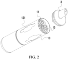
FIG. 2 is a schematic exploded view of a vapor generation apparatus according to an embodiment of this application; -
FIG. 3 is a cross-sectional view of a vapor generation apparatus according to an embodiment of this application; -
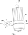
FIG. 4 is a schematic diagram in which a first positioning portion fits with a second holding member according to an embodiment of this application; -
FIG. 5 is a cross-sectional view ofFIG. 4 according to this application; -
FIG. 6 is a schematic diagram of a first assembly according to an embodiment of this application; -
FIG. 7 is a schematic exploded view of a first assembly according to an embodiment of this application; -
FIG. 8 is a schematic diagram of a second assembly according to an embodiment of this application; and -
FIG. 9 is a cross-sectional view ofFIG. 8 . - In the drawings:
- 1: second assembly; 11: atomizer; 111: liquid cup; 112: atomization core; 113: first airway; 12: second holding member; 121: second boss; 1211: second support plane; 1212: second positioning portion; 13: second housing; 131: window; 14: second connection portion; 15: flexible member;
- 2: first assembly; 21: first holding member; 211: first boss; 2111: first support plane; 2112: first positioning portion; 212: first connection portion; 2121: support plate; 2122: connection hole; 22: second housing; 23: air hole; 24: sealing member; 25: connection shaft;
- 3: suction nozzle component; 31: base body; 32: nozzle member;
- 4: power supply component; 41: power supply; 42: circuit board; 43: output electrode group; 431: output electrode;
- 5: reinforcing mechanism; 51: elastic member; 52: first magnetic member; 53: second magnetic member; 6: airflow detector; 7: LED light; and 8: alignment mark.
- The technical solutions in embodiments of this application are clearly and completely described below with reference to the accompanying drawings in the embodiments of this application. Apparently, the described embodiments are merely some rather than all of the embodiments of this application. All other embodiments obtained by a person of ordinary skill in the art based on the embodiments of this application without creative efforts shall fall within the protection scope of this application.
- The terms "first", "second", and "third" in this application are merely intended for a purpose of description, and shall not be understood as indicating or implying relative significance or implicitly indicating the number or sequence of indicated technical features. All directional indications (for example, upper, lower, left, right, front, and rear) in the embodiments of this application are merely used for explaining relative position relationships, movement situations, or the like between the various components in a specific posture (as shown in the accompanying drawings). If the specific posture changes, the directional indications change accordingly. In addition, the terms "include", "have", and any variant thereof are intended to cover a non-exclusive inclusion. For example, a process, method, system, product, or device that includes a series of steps or units is not limited to the listed steps or units, but further optionally includes a step or unit that is not listed, or further optionally includes another step or unit that is intrinsic to the process, method, product, or device.
- "Embodiment" mentioned in the specification means that particular features, structures, or characteristics described with reference to the embodiment may be included in at least one embodiment of this application. The term appearing at different positions of the specification may not refer to the same embodiment or an independent or alternative embodiment that is mutually exclusive with another embodiment. A person skilled in the art explicitly or implicitly understands that the embodiments described in the specification may be combined with other embodiments.
- It should be noted that, when a component is referred to as "being fixed to" another component, the component may be directly on the other component, or an intervening component may be present. When a component is considered to be "connected to" another component, the component may be directly connected to the other component, or one or more intervening components may also be present. The terms "vertical", "horizontal", "left", "right", and similar expressions used in this specification are only for purposes of illustration but not indicate a unique implementation.
- Refer to
FIG. 1 to FIG. 3 , an embodiment of this application provides a vapor generation apparatus. The vapor generation apparatus includes afirst assembly 2 and asecond assembly 1. Thesecond assembly 1 includes a plurality ofatomizers 11 and a second holdingmember 12 configured to hold the plurality ofatomizers 11. "Plurality of in this application means two or more. In an embodiment shown inFIG. 2 , there are a total of fouratomizers 11 included in thesecond assembly 1. The fouratomizers 11 are arranged in an array. - At least two
atomizers 11 of the plurality ofatomizers 11 may be configured to accommodate different liquid substrates. Different liquid substrates include liquid substrates with different tastes or include liquid substrates with different components and proportions. Certainly, in some embodiments, Liquid substrates accommodated by all theatomizers 11 may be the same. - The liquid substrate may include liquid containing a tobacco substance that includes a volatile tobacco flavor component, or may be liquid containing a non-tobacco substance. The liquid substrate may contain water, medicinal liquid, solvent, ethanol, plant extract, fragrance, a flavoring agent, vitamin mixture, or the like. The fragrance may include, but is not limited to, areca nut extract, menthol, peppermint, spearmint oil, various fruit fragrance components, and the like. The flavoring agent may include components that can provide various fragrances or flavors to a user. The vitamin mixture may be a mixture of at least one of vitamin A, vitamin B, vitamin C, and vitamin E, but is not limited thereto. Based on different attributes of the liquid substrate, the vapor generation apparatus may be used in different fields, for example, medical treatment and electronic vapor atomization.
- The
atomizer 11 includes aliquid cup 111 configured to accommodate the liquid substrate and anatomization core 112 in fluid communication with theliquid cup 111. Theatomization core 112 is configured to atomize the liquid substrate, to enable the liquid substrate to generate a vapor. Theatomization core 112 may include a liquid absorbing element and a heating element. The liquid absorbing element may be a porous body or a fiber, and can absorb the liquid substrate and can guide the liquid substrate to an atomization range of the heating element. The heating element is configured to atomize at least a part of the liquid substrate on the liquid absorbing element, to form the vapor. The heating element may be combined on the liquid absorbing element, so that the heating element and the liquid absorbing element can form a whole. - Each
atomizer 11 may further include afirst airway 113. Thefirst airway 113 is in fluid communication with theatomization core 112, and thefirst airway 113 is configured to transfer the vapor. In an example, theatomizer 11 may have an atomization compartment in fluid communication with theliquid cup 111. Theatomization core 112 is accommodated in the atomization compartment, and thefirst airway 113 is in fluid communication with the atomization compartment. Alternatively, refer toFIG. 2 , in another example, at least a part of theatomization core 112 is arranged in theairway 113. - Refer to
FIG. 1 andFIG. 2 , the vapor generation apparatus further includes asuction nozzle component 3. Thesuction nozzle component 3 can be selectively in fluid communication with afirst airway 113 in anyatomizer 11 in thesecond assembly 1, and at least a part of thesuction nozzle component 3 may be held in the mouth of a user, so that the user can inhale a vapor generated by the atomizer by sucking thesuction nozzle component 3. - Refer to
FIG. 3 ,FIG. 5 , andFIG. 6 , the vapor generation apparatus further includes a power supply component 4. The power supply component 4 includes acore 41. The core 41 may be any suitable battery. The power supply component 4 further includes acircuit board 42 and anoutput electrode group 43. Thecircuit board 42 is electrically connected to thecore 41 and theoutput electrode group 43. When theoutput electrode group 43 is electrically connected to theatomizer 11, thecircuit board 42 can control the core 41 to supply power to theoutput electrode group 43, so that theatomization core 112 in theatomizer 11 electrically connected to theoutput electrode group 43 can obtain the power and atomize the liquid substrate. Anoutput electrode 431 in theoutput electrode group 43 may include a positive output electrode and a negative output electrode. The positive output electrode and the negative output electrode are respectively connected to a positive output end and a negative output end of thecore 41. - The
first assembly 2 is rotatably connected to thesecond assembly 1, and a relative position relationship between the plurality ofatomizers 11 in thesecond assembly 1 and thefirst assembly 2 may be changed through rotation. For example, anatomizer 11 at a non-operating position is rotated to an operating position through rotation, and theatomizer 11 at the operating position can be started and can generate a vapor for the user to inhale or use. For example, when a liquid substrate in theatomizer 11 at the operating position is exhausted, through rotation, anew atomizer 11 having a sufficient liquid substrate is at the operating position instead of theatomizer 11 in which the liquid substrate is exhausted. For example, when there is a requirement of changing an inhalation taste, through rotation, anatomizer 11 with another taste is at the operating position instead of anoriginal atomizer 11. - It should be noted that, the operating position can be occupied by only one
atomizer 11 at the same moment. Alternatively, there can be two ormore atomizers 11 at the operating position at same time, so that the user can simultaneously inhale vapors generated by the plurality ofatomizers 11. - In an embodiment, refer to
FIG. 1 to FIG. 3 , at least a part of theliquid cup 111 of theatomizer 11 is transparent, so that the user can observe a remaining volume of a liquid substrate in theliquid cup 111 through a wall of theliquid cup 111, and the user can determine, based on the remaining volume of the liquid substrate in theatomizer 11, whether theatomizer 11 at the operating position needs to be switched. - In embodiments shown in
FIG. 2 to FIG. 4 , theatomizer 11 can be engaged with the second holdingmember 12 in a longitudinal direction and is hold by the second holdingmember 12. At least a part of an outer side of the second holdingmember 12 is open, so that the second holdingmember 12 cannot block or does not fully block a side wall of theliquid cup 111 in theatomizer 11. - The
second assembly 1 may further include asecond housing 13. The second holdingmember 12 and the plurality ofatomizers 11 may be arranged in thesecond housing 13 or are surrounded by thesecond housing 13. Awindow 131 is provided on thesecond housing 13 or at least a part of thesecond housing 13 is transparent, so that the user can observe theliquid cup 111 in theatomizer 11 inside thesecond housing 13 through thewindow 131 or thesecond housing 13 and further observe the remaining volume of the liquid substrate in theatomizer 11. - To facilitate the user determining whether one or
more atomizers 11 in thesecond assembly 1 are rotated to the operating position, or to determine whether one ormore atomizers 11 in thesecond assembly 1 are rotated to a position at which the atomizer can be started, afirst positioning portion 2112 may be arranged on thefirst assembly 2, and asecond positioning portion 1212 is arranged on thesecond assembly 1. When thefirst positioning portion 2112 interferes with thesecond positioning portion 1212, at least oneatomizer 11 in thesecond assembly 1 can be started. Interference includes alignment, contact, embedding, or mutual force interaction, and the like. - Specifically, the
second assembly 1 includes asecond support plane 1211. Thesecond positioning portion 1212 is arranged on thesecond support plane 1211. Thefirst assembly 2 includes afirst support plane 2111. Thefirst positioning portion 2112 is arranged on thefirst support plane 2111. Thefirst support plane 2111 and thesecond support plane 1211 are arranged opposite to each other, so that when the first assembly and thesecond assembly 1 rotate relative to each other, thefirst positioning portion 2112 and thesecond positioning portion 1212 can correspond to each other at a position, so as to interfere with each other. - More specifically, the
first assembly 2 may include a first holdingmember 21. The first holdingmember 21 may be configured to hold or support the power supply component 4, or the first holdingmember 21 may be configured to connect anozzle member 32 or abase body 31 in thesuction nozzle component 3, or the first holdingmember 21 is a constituting part of the power supply component 4 or thesuction nozzle component 3. The first holdingmember 21 is configured to hold thefirst support plane 2111 and thefirst positioning portion 2112. Thefirst positioning portion 2112 may be integrally formed with thefirst support plane 2111 or the first holdingmember 21. Correspondingly, the second holdingmember 12 can hold or support thesecond support plane 1211 and thesecond positioning portion 1212. Thesecond positioning portion 1212 may be integrally formed with the second holdingmember 12 or thesecond support plane 1211. It should be noted that, it is optional rather than necessary that the second holdingmember 12 in thesecond assembly 1 is configured to hold or support thesecond support plane 1211 and thesecond positioning portion 1212. In another embodiment, another member included in thesecond assembly 1 may alternatively be configured to hold or support thesecond support plane 1211 and thesecond positioning portion 1212, and the other member can rotate relative to thefirst assembly 2 and/or can be connected to the second holdingmember 12. - Both at least a part of the
first positioning portion 2112 and at least a part of thesecond positioning portion 1212 are exposed to the outside, are exposed to an outer surface of the vapor generation apparatus, and can be visually observed. Thefirst positioning portion 2112 and thesecond positioning portion 1212 interfere with each other or are staggered, which can be directly felt by the user's vision. As an example, refer toFIG. 1 , a position of interference fit between thefirst positioning portion 2112 and thesecond positioning portion 1212 is visible on the outer surface of the vapor generation apparatus. - In an embodiment, refer to
FIG. 1 ,FIG. 6 , andFIG. 8 , one of thefirst positioning portion 2112 and thesecond positioning portion 1212 includes a protrusion, and the other of the first positioning portion and the second positioning portion includes a groove. When thefirst positioning portion 2112 interferes with thesecond positioning portion 1212, at least a part of the protrusion is located in the groove. When thefirst positioning portion 2112 and thesecond positioning portion 1212 are staggered, the protrusion is located outside the groove and abuts against thefirst support plane 2111 or thesecond support plane 1211. Therefore, when the protrusion slides into the groove from abutting against thefirst support plane 2111 or thesecond support plane 1211, the vapor generation apparatus generates vibration feedback and sends sound feedback, and the user can learn, based on a tactile sense of the vibration and an auditory sense of the sound, that thefirst positioning portion 2112 and thesecond positioning portion 1212 are rotated to interfere with each other. - Because both the at least a part of the
first positioning portion 2112 and the at least a part of thesecond positioning portion 1212 are exposed, the vibration and the sound generated through interference between the first positioning portion and the second positioning portion are more obvious and clear and are more easily perceived by the user. - As an example, when the
first positioning portion 2112 interferes with thesecond positioning portion 1212, the protrusion is located in the groove, and thefirst support plane 2111 is in contact with or abuts against thesecond support plane 1211, so that an interaction force between the first holdingmember 21 and the second holdingmember 12 is uniformly distributed, and when the protrusion slides into the groove, because thefirst support plane 2111 and thesecond support plane 1211 are close to each other, the vibration is more obvious and a vibration range is larger, and because thefirst support plane 2111 and thesecond support plane 1211 are close to each other, the sound is more clear and prominent. - When the
first assembly 2 and thesecond assembly 1 rotate relative to each other, the protrusion and the groove enable thefirst assembly 2 and thesecond assembly 1 to move relative to each other in a longitudinal direction. It should be noted that, the longitudinal direction is perpendicular to a direction in which thefirst assembly 2 and thesecond assembly 1 rotate relative to each other, and the longitudinal direction may be an extending direction of theatomizer 11 or the vapor generation apparatus. - Specifically, when the
first positioning portion 2112 interferes with thesecond positioning portion 1212, the at least a part of the protrusion is located in the groove. In this case, thesecond assembly 1 or thesecond support plane 1211 directly associated with thesecond positioning portion 1212 is located at a first position in the longitudinal direction. When thefirst positioning portion 2112 and thesecond positioning portion 1212 are staggered, the protrusion and the groove are staggered and the protrusion abuts against thefirst support plane 2111 or thesecond support plane 1211. In this case, thesecond assembly 1 or thesecond support plane 1211 directly associated with thesecond positioning portion 1212 is located at a second position in the longitudinal direction. The first position and the second position are two different positions in the longitudinal direction, and the first position and the second position are spaced apart from each other in the longitudinal direction. When thesecond support plane 1211 is located at the first position, thefirst support plane 2111 may abut against thesecond support plane 1211. When thesecond support plane 1211 is located at the second position, thefirst support plane 2111 and thesecond support plane 1211 may be separated from each other, so that there is a gap between the first support plane and the second support plane. - In an embodiment, refer to
FIG. 3 ,FIG. 5 ,FIG. 8 , andFIG. 9 , the vapor generation apparatus further includes a reinforcingmechanism 5. The reinforcing mechanism is configured to increase strength and force of vibration and sound generated when thefirst positioning portion 2112 interferes with thesecond positioning portion 1212, to enhance the vibration and increase the sound, so that the user can more clearly and easily perceive that thefirst positioning portion 2112 has interfered with thesecond positioning portion 1212. Specifically, when thefirst positioning portion 2112 interferes with thesecond positioning portion 1212, or when the protrusion slides into the groove, the reinforcingmechanism 5 provides a driving force for moving thesecond support plane 1211 from the second position to the first position. For example, the reinforcingmechanism 5 pushes the second holdingmember 12 to move from the second position to the first position, to increase the force for fitting between thefirst positioning portion 2111 and thesecond positioning portion 1212. - As an example, refer to
FIG. 5 ,FIG. 8 , andFIG. 9 , afirst connection portion 212 is arranged on the first holdingmember 21, so that a motion state of thefirst connection portion 212 is consistent with a motion state of the first holdingmember 21 or the first assembly. Thesecond assembly 1 further includes asecond connection portion 14. Thesecond connection portion 14 is connected to the second holdingmember 12, so that a motion state of thesecond connection portion 14 is consistent with a motion state of the second holdingmember 12 or thesecond assembly 1. - When the
first positioning portion 2112 interferes with thesecond positioning portion 1212, the reinforcingmechanism 5 acts on thefirst connection portion 212 and thesecond connection portion 14, so that thefirst connection portion 212 and thesecond connection portion 14 are separated from each other. For example, when thefirst positioning portion 2112 interferes with thesecond positioning portion 1212, the reinforcingmechanism 5 can generate an acting force for separating thefirst connection portion 212 and thesecond connection portion 14. In an example, refer toFIG. 3 ,FIG. 8 , andFIG. 9 , the reinforcingmechanism 5 includes anelastic member 51, for example, a spring or an elastic rope. Theelastic member 51 is connected to thefirst connection portion 212 and thesecond connection portion 14. When thefirst positioning portion 2112 and thesecond positioning portion 1212 are staggered, there is a relatively large gap between thefirst support plane 2111 and thesecond support plane 1211. In this case, theelastic member 51 is in a compressed state. Therefore, when thefirst positioning portion 2112 interferes with thesecond positioning portion 1212, the groove provides a recessed space for the protrusion, and thesecond assembly 1 is pushed downward in the longitudinal direction by an elastic force provided by theelastic member 51, so that the protrusion automatically enters the groove, thefirst support plane 2111 and thesecond support plane 1211 are automatically close to each other, and the elastic force provided by theelastic member 51 can further increase force for the protrusion to enter the groove or thefirst support plane 2111 and thesecond support plane 1211 to be close to each other. In an example, refer toFIG. 3 andFIG. 5 , the reinforcingmechanism 5 includes a firstmagnetic member 52 arranged on thefirst connection portion 212 and a secondmagnetic member 53 arranged on thesecond connection portion 14. When thefirst positioning portion 2112 interferes with thesecond positioning portion 1212, the firstmagnetic member 52 and the secondmagnetic member 53 magnetically repel each other, and thesecond assembly 1 is pushed downward in the longitudinal direction by a magnetic repulsion force, so that the protrusion automatically enters the groove, thefirst support plane 2111 and thesecond support plane 1211 are automatically close to each other, and the magnetic repulsion force between the firstmagnetic member 52 and the secondmagnetic member 53 increases force of fitting between thefirst positioning portion 2112 and thesecond positioning portion 1212. - Further, refer to
FIG. 5 andFIG. 9 , thefirst assembly 2 further includes aconnection shaft 25 connected to thesecond connection portion 14. Theconnection shaft 25 extends in the longitudinal direction and a part of the connection shaft extends in the longitudinal direction in the second holdingmember 12. Thefirst connection portion 212 includes asupport plate 2121 and aconnection hole 2122 provided on thesupport plate 2121. Apart of theconnection shaft 25 is located in theconnection hole 2122, and when moving between the first position and the second position, thesecond support plane 1211 may move up and down in the longitudinal direction in theconnection hole 2122. At least a part of the second holdingmember 12 and thesecond connection portion 14 are located on two opposite sides of theconnection hole 2122. When the reinforcingmechanism 5 includes theelastic member 51, theelastic member 51 is arranged between thesupport plate 2121 and thesecond connection portion 14. Theelastic member 51 may be always in the compressed state or theelastic member 51 may be in the compressed state only when thefirst positioning portion 2112 and thesecond positioning portion 1212 are staggered. When the reinforcingmechanism 5 includes the firstmagnetic member 52 and the secondmagnetic member 53 that magnetically repel each other, the firstmagnetic member 52 is fixed on thesupport plate 2121, and the secondmagnetic member 53 is fixed on thesecond connection portion 14. - A size of the
second connection portion 14 extending in a horizontal direction is greater than a size of theconnection hole 2122, to prevent thesecond connection portion 14 from passing through theconnection hole 2122, so that the first holdingmember 21 and the second holdingmember 12 are not separable. - It should be noted that, it is optional rather than necessary that when the
first positioning portion 2112 interferes with thesecond positioning portion 1212, the reinforcingmechanism 5 enables thefirst connection portion 212 and thesecond connection portion 14 to be separated from each other. Alternatively, in another example, when the first positioning portion interferes with the second positioning portion, the reinforcing mechanism acts on the first connection portion and the second connection portion, so that the first connection portion and the second connection portion are close to each other. For example, when the first positioning portion interferes with the second positioning portion, the reinforcing mechanism can generate an acting force for pulling the first connection portion and the second connection portion together. In an example, the reinforcing mechanism includes an elastic member, for example, a spring or an elastic rope. The elastic member is connected to the first connection portion and the second connection portion. When the first positioning portion and the second positioning portion are staggered, there is a relatively large gap between the first support plane and the second support plane. In this case, the elastic member is in a stretched state. Therefore, when the first positioning portion interferes with the second positioning portion, the groove provides a recessed space for the protrusion, and under elastic resilience of the elastic member, the protrusion automatically enters the groove, the first support plane and the second support plane are automatically close to each other, and the elastic force provided by the elastic member can further increase force for the protrusion to enter the groove or the first support plane and the second support plane to be close to each other. In an example, the reinforcing mechanism includes a first magnetic member arranged on the first connection portion and a second magnetic member arranged on the second connection portion. When the first positioning portion interferes with the second positioning portion, the first magnetic member and the second magnetic member magnetically attract each other, and through a magnetic attraction force, the protrusion automatically enters the groove, the first support plane and the second support plane are automatically close to each other, and the magnetic attraction force between the first magnetic member and the second magnetic member increases force of fitting between the first positioning portion and the second positioning portion. - Based on a first aspect of this application, the
first assembly 2 includes the power supply component 4. Therefore, the power supply component 4 and thesecond assembly 1 can rotate relative to each other. When thefirst positioning portion 2112 interferes with thesecond positioning portion 1212 through rotation, feedback that at least oneatomizer 11 in thesecond assembly 1 is electrically connected to the power supply component 4 can be provided. - In an embodiment shown in
FIG. 6 , the power supply component 4 has only oneoutput electrode group 43, so that the power supply component 4 can supply power to only oneatomizer 11 of the plurality ofatomizers 11 in thesecond assembly 1 at same time, and only theatomizer 11 can be started and generates a vapor. Therefore, in this embodiment, the power supply component 4 and thesecond assembly 1 may rotate relative to each other, to switch theatomizer 11 at the operating position, so that oneatomizer 11 of the plurality ofatomizers 11 is electrically connected to the uniqueoutput electrode group 43 in the power supply component 4, and the remainingatomizers 11 are not electrically connected to the power supply component 4. - Alternatively, in another embodiment, the power supply component may have a plurality of output electrode groups. The plurality of output electrode groups are respectively electrically connected to the plurality of atomizers, and a power supply may be controlled through the circuit board to supply power to one or more atomizers, so that one or more atomizers can be started and generate a vapor. Therefore, in this embodiment, the power supply component and the second assembly may rotate relative to each other, to switch the atomizer at the operating position, so that one or more atomizers of the plurality of atomizers are electrically connected to one or more output electrode groups in the power supply component, and some atomizers in the second assembly are not electrically connected to the power supply component.
- In some embodiments of this application, when the
second support plane 1211 moves between the first position and the second position, theatomizer 11 in thesecond assembly 1 can move in the longitudinal direction with thesecond support plane 1211. - Therefore, when the
first positioning portion 2112 interferes with thesecond positioning portion 1212 through rotation, thesecond support plane 1211 is located at the first position in the longitudinal direction. In this case, anoutput electrode 431 in theoutput electrode group 43 abuts against a correspondingatomizer 11 in thesecond assembly 1 and is electrically connected to the correspondingatomizer 11. When thefirst positioning portion 2112 and thesecond positioning portion 1212 are staggered through rotation, thesecond support plane 1211 is located at the second position in the longitudinal direction longitudinally spaced from the first position. In this case, theoutput electrode 431 in theoutput electrode group 43 is separated from theatomizer 11 in thesecond assembly 1 or an acting force of abutment between theoutput electrode 431 and thesecond assembly 1 is reduced. - Therefore, when the
second support plane 1211 is located at the second position in the longitudinal direction and the first holdingmember 21 and the second holdingmember 12 rotate relative to each other, theoutput electrode 431 can keep spaced from or keep no contact with thesecond assembly 1, or theoutput electrode 431 and thesecond assembly 1 can maintain a relatively small abutment acting force. Therefore, theoutput electrode 431 can be prevented from deviating due to a shear force, and theoutput electrode 431 or the output electrode of theatomizer 11 can be prevented from being damaged or deformed. - Based on the first aspect, in an embodiment, refer to
FIG. 6 , anair hole 23 in communication with the outside is provided on the first holdingmember 21. When the user sucks thesuction nozzle component 3, external air enters theatomizer 11 at the operating position through theair hole 23 and then enters an oral cavity of the user through thesuction nozzle component 3. - Further, a sealing
member 24 is further arranged on the first holdingmember 21. The sealingmember 24 surrounds theair hole 23, the sealingmember 24 elastically abuts against thesecond assembly 1, and the sealingmember 24 and the first holdingmember 21 may be combined through a two-color injection molding process or a two-time injection molding process. - There may be only one
air hole 23 on the first holdingmember 21. Therefore, the sealingmember 24 may surround theair hole 23, and the sealingmember 24 elastically abuts against thesecond assembly 1 and surrounds a periphery of an air inlet of theatomizer 11 at the operating position. Therefore, during inhalation, the external air can be prevented from entering theatomizer 11 at the non-operating position and gas in theatomizer 11 at the non-operating position can be prevented from entering theatomizer 11 in an operating state. This is beneficial to ensure a taste of inhalation. - Alternatively, there may be a plurality of air holes on the first holding member. The sealing member is provided with a plurality of annular holes. The plurality of annular holes are respectively provided around different air holes. Alternatively, there are a plurality of sealing members, and the plurality of sealing members respectively surround different air holes. When the first positioning portion interferes with the second positioning portion, the plurality of annular holes on the sealing member or the plurality of sealing members respectively surround peripheries of air inlets of different atomizers. Therefore, during inhalation, gas in the atomizer at the non-operating position can be prevented from entering the atomizer in the operating state. This is beneficial to ensure a taste of inhalation.
- Based on the first aspect, in an embodiment, refer to
FIG. 3 , the vapor generation apparatus may include anairflow detector 6. Theairflow detector 6 may determine, based on an airflow change in the vapor generation apparatus, whether the vapor generation apparatus is being sucked, and when detecting that the vapor generation apparatus is being sucked, the airflow detector can control the core 41 to supply power to theatomizer 11 at the operating position, so that theatomization core 112 in theatomizer 11 atomizes a liquid substrate to generate a vapor. - Based on the first aspect, in an embodiment, refer to
FIG. 3 andFIG. 7 , thefirst assembly 2 further includes afirst housing 22. The power supply component 4 is arranged in thefirst housing 22, and the power supply component 4 and thefirst housing 22 have motion consistency. Both thefirst housing 22 and thesecond housing 13 extend in the longitudinal direction. A part of the first holdingmember 21 extends in a horizontal direction to form afirst boss 211. At least a part of thefirst boss 211 is located between thefirst housing 22 and thesecond housing 13. A part of the second holdingmember 12 extends in the horizontal direction to form asecond boss 121. At least a part of thesecond boss 121 is located between thefirst housing 22 and thesecond housing 13. Thefirst support plane 2111 and thefirst positioning portion 2112 are formed on thefirst boss 211 and are constituting parts of thefirst boss 211. Thesecond support plane 1211 and thesecond positioning portion 1212 are formed on thesecond boss 121 and are constituting parts of thesecond boss 121. Therefore, both at least a part of thefirst support plane 2111 and at least a part of thesecond support plane 1211 are located between thefirst housing 22 and thesecond housing 13, and both at least a part of thefirst positioning portion 2112 and at least a part of thesecond positioning portion 1212 are located between thefirst housing 22 and thesecond housing 13, so that thefirst housing 22 and thesecond housing 13 do not block outer sides of thefirst positioning portion 2112 and thesecond positioning portion 1212. - As an example, refer to
FIG. 5 , at least a part of the first holdingmember 21 or at least a part of the second holdingmember 12 is made of a transparent material. Thefirst boss 211 or thesecond boss 121 is made of a transparent material. AnLED light 6 is arranged in the vapor generation apparatus. When theLED light 6 emits light, the transparent material inside thefirst housing 22 or thesecond housing 13 can guide the light to thefirst boss 211 or thesecond boss 121. Because an outer side of thefirst boss 211 and an outer side of thesecond boss 121 are not blocked and are exposed, the light can be perceived by the user's vision. Therefore, when theLED light 6 emits the light, thefirst boss 211 or thesecond boss 121 can generate light, so that an appearance of the vapor generation apparatus is more beautiful, to improve user experience. - Based on the first aspect, in an embodiment, the
suction nozzle component 3 is rotatably connected to thesecond assembly 1, so that thesuction nozzle component 3 is in fluid communication with at least oneatomizer 11 in thesecond assembly 1 through rotation. - Based on the first aspect, in an embodiment, the
second assembly 1 is rotatably connected between thesuction nozzle component 3 and the power supply component 4, so that thesuction nozzle component 3 is in fluid communication with at least oneatomizer 11 in thesecond assembly 1 through rotation. Specifically, two opposite ends of theconnection shaft 25 are respectively connected to thesuction nozzle component 3 and the power supply component 4. The second holdingmember 12 or the plurality ofatomizers 11 in thesecond assembly 1 can rotate around theconnection shaft 25 and rotate relative to thesuction nozzle component 3 and the power supply component 4 by rotating around theconnection shaft 25. When the second holdingmember 12 or the plurality ofatomizers 11 rotate, theconnection shaft 25, thesuction nozzle component 3, and the power supply component 4 may maintain motion consistency, for example, keep no rotation simultaneously. - The
suction nozzle component 3 includes thebase body 31 and thenozzle member 32 arranged on thebase body 31. At least a part of thenozzle member 32 may be held in the mouth of the user. Thenozzle member 32 is arranged away from a central axis of thebase body 31. When thefirst positioning portion 2112 interferes with thesecond positioning portion 1212, thenozzle member 32 can correspond to or can be aligned with oneoutput electrode group 43 in the power supply component 4 in the longitudinal direction. Therefore, the second holdingmember 12 or the plurality ofatomizers 11 rotate, oneatomizer 11 of the plurality ofatomizers 11 can be electrically connected to theoutput electrode group 43 in the power supply component 4, and theatomizer 11 electrically connected to the power supply component 4 can be further in fluid communication with thesuction nozzle component 3. - In some embodiments of this application, connection between the second holding
member 12 and theconnection shaft 25 enables thesecond assembly 1 and theconnection shaft 25 to move up and down together in the longitudinal direction. Therefore, theatomizer 11 in thesecond assembly 1 can move in the longitudinal direction with thesecond support plane 1211. - In the embodiment shown in
FIG. 2 , thesecond assembly 1 further includes aflexible member 15. Theflexible member 15 is elastic and includes silicone, rubber, a spring, or the like. Theflexible member 15 elastically abuts against thebase body 31. Therefore, thesuction nozzle component 3 can apply a longitudinal acting force to thesecond assembly 1 through theflexible member 15, so that when thefirst positioning portion 2112 interferes with thesecond positioning portion 1212, thefirst positioning portion 2112 is aligned with thesecond positioning portion 1212, and thesuction nozzle component 3 can provide, through theflexible member 15, a driving force for moving thesecond support plane 1211 from the second position to the first position, that is, theflexible member 15 may be a constituting part of a reinforcing structure. When thefirst positioning portion 2112 and thesecond positioning portion 1212 are staggered, the flexibility of theflexible part 15 enables thesecond support plane 1211 to move from the first position to a recessed space of the first position. - It should be noted that, a third positioning member that is at least partially exposed may be arranged on the
suction nozzle component 3. A fourth positioning member that is at least partially exposed may be arranged on thesecond assembly 1. When the third positioning member interferes with the fourth positioning member, thesuction nozzle component 3 is in fluid communication with at least oneatomizer 11. The third positioning member and the fourth positioning member may have same features as thefirst positioning portion 2112 and thesecond positioning portion 1212. Details are not described herein again. - Based on the first aspect, in an embodiment, the
first support plane 2111 and thesecond support plane 1211 are arranged opposite to each other in the longitudinal direction. In the longitudinal direction, thesecond assembly 1 is located between thesuction nozzle component 3 and the power supply component 4. - Based on the first aspect, in an embodiment, refer to
FIG. 4 andFIG. 6 , onefirst positioning portion 2112 and/or onesecond positioning portion 1212 has analignment mark 8. When the first assembly and thesecond assembly 1 are assembled, a mark on thefirst housing 22 and/or a mark on thesecond housing 13 may be aligned by using thealignment mark 8, so that the first assembly and thesecond assembly 1 are engaged in a preset direction. - Based on the first aspect, in an embodiment, refer to
FIG. 3 , there is a dampingmember 16 between thefirst assembly 2 and thesecond assembly 1. The dampingmember 16 is fixed on one of thefirst assembly 2 and thesecond assembly 1 and is rotatably connected to the other of the first assembly and the second assembly with damping, to provide resistance for preventing relative rotation of thefirst assembly 2 and thesecond assembly 1. Therefore, when an external force that drives the relative rotation of thefirst assembly 2 and thesecond assembly 1 is revoked or reduced to be less than rotation damping provided by the dampingmember 16, thefirst assembly 2 and thesecond assembly 1 can be maintained at a rotation stop position, so as to prevent switching of theatomizer 11 electrically connected to the power supply component 4 without expectation, which helps a stable and reliable electrical connection between the power supply component 4 and theatomizer 11 at the operating position. - As an example, the damping
member 16 provides resistance for preventing the relative rotation of thefirst assembly 2 and thesecond assembly 1 as a friction force. For example, the dampingmember 16 includes a damping ring made of a material like silicone or rubber with a relatively high friction coefficient and wear resistance. The damping ring can be fixed or arranged on the first holdingmember 21, and may be supported by thefirst support plane 2111. The second holdingmember 12 is arranged on a periphery of the damping ring and rotates relative to the damping ring, so that the damping ring is sandwiched between an inner side of the second holdingmember 12 and an outer side of the first holdingmember 21. - Based on a second aspect of this application, the
first assembly 1 includes asuction nozzle component 3. Therefore, thesuction nozzle component 3 and thesecond assembly 1 can rotate relative to each other. When thefirst positioning portion 2112 interferes with thesecond positioning portion 1212 through rotation, feedback that at least oneatomizer 11 in thesecond assembly 1 is in fluid communication with thesuction nozzle component 3 can be provided. - In the embodiment shown in
FIG. 1 , anozzle member 32 in thesuction nozzle component 3 is arranged away from a central axis of abase body 31 in thesuction nozzle component 3, and thenozzle member 32 is configured to be in fluid communication with only oneatomizer 11 at same time, so that only theatomizer 11 can be started and generates a vapor. - Therefore, in this embodiment, the
suction nozzle component 3 and thesecond assembly 1 may rotate relative to each other, to switch theatomizer 11 at the operating position, so that oneatomizer 11 of the plurality ofatomizers 11 is in fluid communication with the uniquesuction nozzle component 3, and the remainingatomizers 11 are fluid isolated from thesuction nozzle component 3. - Based on the second aspect, in an embodiment, the power supply component has a plurality of output electrode groups. The plurality of output electrode groups are electrically connected to the plurality of atomizers in a one-to-one correspondence.
- Based on the second aspect, the vapor generation apparatus may have a selection switch or a plurality of independent switches. After the
suction nozzle component 3 is in fluid communication with one of theatomizers 11 through rotation, the power supply component 4 may be controlled through the switch to supply power to theatomizer 11. - Alternatively, the vapor generation apparatus includes a plurality of air inlet channels and a plurality of
airflow detectors 6, the plurality of air inlet channels are respectively in communication with the plurality ofatomizers 11 in a one-to-one correspondence, and the plurality ofairflow detectors 6 respectively detect airflow changes in the plurality of air inlet channels. After thesuction nozzle component 3 is in fluid communication with one of theatomizers 11 through rotation, the user may directly suck thesuction nozzle component 3. External air enters theatomizer 11 in fluid communication with thesuction nozzle component 3 through a corresponding air inlet channel, and acorresponding airflow detector 6 determines that theatomizer 11 corresponding to the airflow detector is inhaled because a change of an airflow is detected. Therefore, the power supply component 4 is automatically controlled to supply power to theatomizer 11, so that theatomizer 11 generates a vapor. - Based on the second aspect, the power supply component 4 and the
second assembly 1 may have motion consistency, and the power supply component and the second assembly may not rotate relative to each other. - Based on any one of the foregoing embodiments, a quantity of
first positioning portions 2112 may be the same as a quantity ofatomizers 11, and/or a quantity ofsecond positioning portions 1212 may be the same as a quantity ofatomizers 11. It should be noted that, the specification of this application and the accompanying drawings thereof illustrate preferred embodiments of this application, but are not limited to the embodiments described in this specification, furthermore, a person of ordinary skill in the art may make improvements or modifications according to the foregoing description, and all the improvements and modifications shall fall within the protection scope of the attached claims of this application.
Claims (15)
- A vapor generation apparatus, comprising:a first assembly (2), comprising a first support plane (2111), wherein a first positioning portion (2112) that is at least partially exposed is arranged on the first support plane (2111); anda second assembly (1), rotatably connected to the first assembly (2), wherein the second assembly (1) comprises a plurality of atomizers (11) and a second support plane (1211), and a second positioning portion (1212) that is at least partially exposed is arranged on the second support plane (1211), whereinthe first support plane (2111) and the second support plane (1211) are arranged opposite to each other, and when the first assembly (2) and the second assembly (1) are rotatable relative to each other, the first positioning portion (2112) is capable of being in interference fit with the second positioning portion (1212), to provide feedback that at least one atomizer (11) in the second assembly (1) is startable.
- The vapor generation apparatus according to claim 1, wherein a position of interference fit between the first positioning portion (2112) and the second positioning portion (1212) is visible on an outer surface of the vapor generation apparatus.
- The vapor generation apparatus according to claim 1, wherein one of the first positioning portion (2112) and the second positioning portion (1212) comprises a protrusion, the other of the first positioning portion (2112) and the second positioning portion (1212) comprises a groove, when the first positioning portion (2112) is aligned with the second positioning portion (1212), at least a part of the protrusion is located in the groove, and when the first positioning portion (2112) and the second positioning portion (1212) are staggered, the protrusion is located outside the groove and abuts against the first support plane (2111) or the second support plane (1211).
- The vapor generation apparatus according to claim 3, wherein when the first positioning portion (2112) interferes with the second positioning portion (1212), the second support plane (1211) is located at a first position in a longitudinal direction, and when the first positioning portion (2112) and the second positioning portion (1212) are staggered, the second support plane (1211) is located at a second position in the longitudinal direction longitudinally spaced from the first position.
- The vapor generation apparatus according to claim 4, wherein the vapor generation apparatus further comprises a reinforcing mechanism (5), wherein the reinforcing mechanism (5) is configured to provide a driving force for moving the second support plane (1211) from the second position to the first position when the first positioning portion (2112) rotates to an orientation aligned with the second positioning portion (1212).
- The vapor generation apparatus according to claim 4, wherein the first assembly (2) further comprises a first connection portion (212), and the second assembly (1) further comprises a second connection portion (14); andthe reinforcing mechanism (5) comprises an elastic member (51) that connects the first connection portion (212) and the second connection portion (14), and when the first positioning portion (2112) and the second positioning portion (1212) are staggered, the elastic member (51) is in stretched state or a compressed state; orthe reinforcing mechanism (5) comprises a first magnetic member (52) arranged on the first connection portion (212) and a second magnetic member (53) arranged on the second connection portion (14), and when the first positioning portion (2112) interferes with the second positioning portion (1212), the first magnetic member (52) and the second magnetic member (53) magnetically attract or repel each other.
- The vapor generation apparatus according to claim 6, wherein the second assembly (1) further comprises a second holding member (12) for holding the plurality of atomizers (11), the first assembly (2) further comprises a connection shaft (25) connected to the second connection portion (14), a support plate (2121), and a connection hole (2122) provided on the support plate (2121), and a part of the connection shaft (25) is located in the connection hole (2122) and a part of the connection shaft (25) extends in the longitudinal direction in the first assembly (2);when the second support plane (1211) moves between the first position and the second position, the connection shaft (25) moves in the longitudinal direction in the connection hole (2122), and the second holding member (12) and the second connection portion (14) are located on two opposite sides of the connection hole (2122); anda size of the second connection portion (14) extending in a horizontal direction is greater than a hole diameter of the connection hole (2122).
- The vapor generation apparatus according to any one of claims 1 to 6, wherein the first assembly (2) further comprises a power supply component (4), and when the first positioning portion (2112) interferes with the second positioning portion (1212) through rotation, at least one atomizer (11) in the second assembly (1) is electrically connected to the power supply component (4).
- The vapor generation apparatus according to claim 8, wherein the power supply component (4) comprises a core and an output electrode group (43) connected to the core, and the output electrode group (43) is fixed on the first holding member (21); and
when the first positioning portion (2112) interferes with the second positioning portion (1212), the output electrode group (43) is electrically connected to one of the atomizers (11). - The vapor generation apparatus according to claim 8, wherein the first holding member (21) is provided with a sealing member (24) and an air hole (23) in communication with the outside, the sealing member (24) surrounds the air hole (23), and the sealing member (24) elastically abuts against the second assembly (1); and
when the first positioning portion (2112) interferes with the second positioning portion (1212), the air hole (23) is in fluid communication with one of the atomizers (11). - The vapor generation apparatus according to claim 8, wherein the first assembly (2) further comprises a first housing, and the power supply component (4) is arranged in the first housing;the second assembly (1) further comprises a second housing, and the plurality of atomizers (11) are arranged in the second housing; andat least a part of the first positioning portion (2112) and at least a part of the second positioning portion (1212) are located between the first housing and the second housing.
- The vapor generation apparatus according to claim 8, wherein the vapor generation apparatus further comprises a suction nozzle component (3), and the second assembly (1) is rotatably connected between the suction nozzle component (3) and the power supply component (4), to enable the suction nozzle component (3) to be in fluid communication with at least one atomizer (11) in the second assembly (1) through rotation.
- The vapor generation apparatus according to any one of claims 1 to 6, wherein the first assembly (2) further comprises a suction nozzle component (3), and when the first positioning portion (2112) interferes with the second positioning portion (1212) through rotation, at least one atomizer (11) in the second assembly (1) is in fluid communication with the suction nozzle component (3).
- The vapor generation apparatus according to any one of claims 1 to 6, wherein a quantity of first positioning portions (2112) is the same as a quantity of atomizers (11); and/or
a quantity of second positioning portions (1212) is the same as a quantity of atomizers (11). - The vapor generation apparatus according to any one of claims 1 to 6, wherein the vapor generation apparatus further comprises a damping member (16), the damping member (16) is fixedly connected to one of the first assembly (2) and the second assembly (1) and is rotatably connected to the other of the first assembly (2) and the second assembly (1) with damping, to provide resistance to prevent relative rotation of the first assembly (2) and the second assembly (1).
Applications Claiming Priority (1)
| Application Number | Priority Date | Filing Date | Title |
|---|---|---|---|
| CN202323371728.9U CN221653627U (en) | 2023-12-11 | 2023-12-11 | Aerosol generating device |
Publications (1)
| Publication Number | Publication Date |
|---|---|
| EP4570087A1 true EP4570087A1 (en) | 2025-06-18 |
Family
ID=90365452
Family Applications (1)
| Application Number | Title | Priority Date | Filing Date |
|---|---|---|---|
| EP24163383.3A Pending EP4570087A1 (en) | 2023-12-11 | 2024-03-13 | Vapor generation apparatus |
Country Status (3)
| Country | Link |
|---|---|
| EP (1) | EP4570087A1 (en) |
| CN (1) | CN221653627U (en) |
| GB (1) | GB2626089B (en) |
Citations (1)
| Publication number | Priority date | Publication date | Assignee | Title |
|---|---|---|---|---|
| US20160366940A1 (en) * | 2014-02-28 | 2016-12-22 | Kimree Hi-Tech Inc. | Electronic cigarette and electronic cigarette atomization control method |
Family Cites Families (1)
| Publication number | Priority date | Publication date | Assignee | Title |
|---|---|---|---|---|
| CN217471245U (en) * | 2022-04-18 | 2022-09-23 | 深圳市雷霆风暴科技有限公司 | Combined electronic cigarette with multiple tastes |
-
2023
- 2023-12-11 CN CN202323371728.9U patent/CN221653627U/en active Active
-
2024
- 2024-03-13 GB GB2403645.1A patent/GB2626089B/en active Active
- 2024-03-13 EP EP24163383.3A patent/EP4570087A1/en active Pending
Patent Citations (1)
| Publication number | Priority date | Publication date | Assignee | Title |
|---|---|---|---|---|
| US20160366940A1 (en) * | 2014-02-28 | 2016-12-22 | Kimree Hi-Tech Inc. | Electronic cigarette and electronic cigarette atomization control method |
Also Published As
| Publication number | Publication date |
|---|---|
| GB2626089B (en) | 2025-01-01 |
| CN221653627U (en) | 2024-09-06 |
| GB202403645D0 (en) | 2024-04-24 |
| GB2626089A (en) | 2024-07-10 |
Similar Documents
| Publication | Publication Date | Title |
|---|---|---|
| EP4461147B1 (en) | Aerosol generation device | |
| WO2015127663A1 (en) | Electronic cigarette and electronic cigarette vaporization control method | |
| EP4461148A1 (en) | Aerosol generation apparatus | |
| EP4527218A2 (en) | Aerosol generation device | |
| CN218457270U (en) | Position adjusting assembly and atomizing device capable of switching flavors | |
| CN112273728A (en) | A power supply assembly and electronic atomization device | |
| CN220712903U (en) | Aerosol generating device | |
| WO2019196688A1 (en) | Atomizer and electronic cigarette | |
| JP7303937B2 (en) | aerosol generator | |
| KR20210009309A (en) | Aerosol generating device comprising two nebulizer assemblies | |
| CN217826746U (en) | Aerosol generating device | |
| CN116326838B (en) | Atomizer and aerosol generating device | |
| GB2626089A (en) | Vapor generation apparatus | |
| CN212306815U (en) | an electronic cigarette | |
| EP4085772A1 (en) | Atomizer, and aerosol generation device | |
| CN218418445U (en) | Electronic atomization device | |
| CN222109279U (en) | Aerosol generating device | |
| WO2025161930A1 (en) | Aerosol generation apparatus and atomizer | |
| CN217184824U (en) | Atomizer base and atomizer | |
| CN222303089U (en) | Aerosol generating device | |
| CN220192167U (en) | Atomizer and aerosol generating device with child lock function | |
| CN220109084U (en) | Ultrasonic atomizer and ultrasonic atomizing device | |
| CN223310646U (en) | Aerosol generating device | |
| CN221284669U (en) | Aerosol generating device | |
| CN222941782U (en) | Aerosol generating device |
Legal Events
| Date | Code | Title | Description |
|---|---|---|---|
| PUAI | Public reference made under article 153(3) epc to a published international application that has entered the european phase |
Free format text: ORIGINAL CODE: 0009012 |
|
| STAA | Information on the status of an ep patent application or granted ep patent |
Free format text: STATUS: REQUEST FOR EXAMINATION WAS MADE |
|
| 17P | Request for examination filed |
Effective date: 20240313 |
|
| AK | Designated contracting states |
Kind code of ref document: A1 Designated state(s): AL AT BE BG CH CY CZ DE DK EE ES FI FR GB GR HR HU IE IS IT LI LT LU LV MC ME MK MT NL NO PL PT RO RS SE SI SK SM TR |
|
| STAA | Information on the status of an ep patent application or granted ep patent |
Free format text: STATUS: EXAMINATION IS IN PROGRESS |
|
| 17Q | First examination report despatched |
Effective date: 20251010 |