EP4570086A1 - Aerosol provision device - Google Patents
Aerosol provision device Download PDFInfo
- Publication number
- EP4570086A1 EP4570086A1 EP24154010.3A EP24154010A EP4570086A1 EP 4570086 A1 EP4570086 A1 EP 4570086A1 EP 24154010 A EP24154010 A EP 24154010A EP 4570086 A1 EP4570086 A1 EP 4570086A1
- Authority
- EP
- European Patent Office
- Prior art keywords
- aerosol
- protrusions
- lid unit
- unit
- lid
- Prior art date
- Legal status (The legal status is an assumption and is not a legal conclusion. Google has not performed a legal analysis and makes no representation as to the accuracy of the status listed.)
- Pending
Links
Images








Classifications
-
- A—HUMAN NECESSITIES
- A24—TOBACCO; CIGARS; CIGARETTES; SIMULATED SMOKING DEVICES; SMOKERS' REQUISITES
- A24F—SMOKERS' REQUISITES; MATCH BOXES; SIMULATED SMOKING DEVICES
- A24F40/00—Electrically operated smoking devices; Component parts thereof; Manufacture thereof; Maintenance or testing thereof; Charging means specially adapted therefor
- A24F40/40—Constructional details, e.g. connection of cartridges and battery parts
-
- A—HUMAN NECESSITIES
- A24—TOBACCO; CIGARS; CIGARETTES; SIMULATED SMOKING DEVICES; SMOKERS' REQUISITES
- A24F—SMOKERS' REQUISITES; MATCH BOXES; SIMULATED SMOKING DEVICES
- A24F40/00—Electrically operated smoking devices; Component parts thereof; Manufacture thereof; Maintenance or testing thereof; Charging means specially adapted therefor
- A24F40/10—Devices using liquid inhalable precursors
-
- A—HUMAN NECESSITIES
- A24—TOBACCO; CIGARS; CIGARETTES; SIMULATED SMOKING DEVICES; SMOKERS' REQUISITES
- A24F—SMOKERS' REQUISITES; MATCH BOXES; SIMULATED SMOKING DEVICES
- A24F40/00—Electrically operated smoking devices; Component parts thereof; Manufacture thereof; Maintenance or testing thereof; Charging means specially adapted therefor
- A24F40/20—Devices using solid inhalable precursors
-
- B—PERFORMING OPERATIONS; TRANSPORTING
- B65—CONVEYING; PACKING; STORING; HANDLING THIN OR FILAMENTARY MATERIAL
- B65D—CONTAINERS FOR STORAGE OR TRANSPORT OF ARTICLES OR MATERIALS, e.g. BAGS, BARRELS, BOTTLES, BOXES, CANS, CARTONS, CRATES, DRUMS, JARS, TANKS, HOPPERS, FORWARDING CONTAINERS; ACCESSORIES, CLOSURES, OR FITTINGS THEREFOR; PACKAGING ELEMENTS; PACKAGES
- B65D43/00—Lids or covers for rigid or semi-rigid containers
- B65D43/14—Non-removable lids or covers
- B65D43/20—Non-removable lids or covers linearly slidable
Definitions
- the present disclosure relates to the field of providing aerosols.
- the present disclosure relates to an aerosol provision device.
- the present disclosure also relates to an aerosol provision system and to a method of generating an aerosol.
- Smoking items such as cigarettes, cigars and the like traditionally burn tobacco during use, producing tobacco smoke. Efforts are being made to create alternatives to such items. In this regard, it may be envisaged in particular to heat, but not burn, a suitable material to release certain compounds, particularly in an inhalable aerosol.
- a suitable material may or may not contain tobacco and may or may not contain nicotine.
- Such a material may, e.g., be provided in a cylindrical unit or, more generally, an article comprising an aerosol generating material.
- an aerosol provision device for generating aerosol from aerosol generating material, the device comprising:
- the guiding arrangement may comprise a flat base extending in a plane and a covering unit, wherein the lid unit comprises structures engaging in a groove formed between the flat base and the covering unit.
- the guiding structures may comprise at least one of protrusions arranged at the flat base, protrusions arranged at the covering unit, and protrusions arranged at the lid unit.
- the lifting protrusions may comprise sections of opposite slopes.
- a flat section between said sections of opposite slopes and particularly parallel to a surface of the lid unit may be provided.
- the protrusions may be provided in a curved or straight shape in a sectional view, wherein the sectional view is in particular a sectional view in a plane orthogonal to a surface of the lid unit and parallel to the sliding direction.
- the protrusions may protrude 0.01 to 0.5 mm, 0.025 to 0.075 or about 0.05 mm from adjacent regions parallel to a surface of the lid unit.
- the protrusions may be formed integrally with or separately from a material of adjacent regions.
- first protrusions spaced apart by a protrusion distance may be arranged at the covering unit along the sliding direction and second protrusions comprising a maximum height at a position corresponding to a position within the protrusion distance may be arranged at the base, or vice versa, wherein skids of the lid unit are interposed between the first protrusions and the second protrusions.
- the protrusions may be arranged at opposite ends or central positions at least one of the base, the covering unit, and the lid unit.
- a system comprising a device according to any possible embodiment disclosed herein and an article including the aerosol generating material is also provided.
- a method of generating an aerosol including providing an aerosol provision system as indicated above; and operating the aerosol provision system.
- aerosol-generating material is a material that is capable of generating aerosol, for example when heated, irradiated or energized in any other way.
- Aerosol-generating material may, for example, be in the form of a solid, liquid or gel which may or may not contain an active substance and/or flavourants.
- Aerosol-generating material may include any plant based material, such as tobacco-containing material and may, for example, include one or more of tobacco, tobacco derivatives, expanded tobacco, reconstituted tobacco or tobacco substitutes. Aerosol-generating material also may include other, non-tobacco, products, which, depending on the product, may or may not contain nicotine.
- Aerosol-generating material may for example be in the form of a solid, a liquid, a gel, a wax or the like. Aerosol-generating material may for example also be a combination or a blend of materials. Aerosol-generating material may also be known as "smokable material".
- the aerosol-generating material may comprise a binder and an aerosol former.
- an active and/or filler may also be present.
- a solvent such as water, is also present and one or more other components of the aerosol-generating material may or may not be soluble in the solvent.
- the aerosol-generating material is substantially free from botanical material. In some embodiments, the aerosol-generating material is substantially tobacco free.
- the aerosol-generating material may comprise or be an "amorphous solid".
- the amorphous solid may be a "monolithic solid".
- the amorphous solid may be a dried gel.
- the amorphous solid is a solid material that may retain some fluid, such as liquid, within it.
- the aerosol-generating material may, for example, comprise from about 50wt%, 60wt% or 70wt% of amorphous solid, to about 90wt%, 95wt% or 100wt% of amorphous solid.
- the aerosol-generating material may comprise an aerosol-generating film.
- the aerosol-generating film may comprise or be a sheet, which may optionally be shredded to form a shredded sheet.
- the aerosol-generating sheet or shredded sheet may be substantially tobacco free.
- a "non-combustible" aerosol provision system is one where a constituent aerosol-generating material of the aerosol provision system (or component thereof) is not combusted or burned in order to facilitate delivery of at least one substance to a user.
- the delivery system is a non-combustible aerosol provision system, such as a powered non-combustible aerosol provision system.
- the non-combustible aerosol provision system is an electronic cigarette, also known as a vaping device or electronic nicotine delivery system (END), although it is noted that the presence of nicotine in the aerosol-generating material is not a requirement.
- END electronic nicotine delivery system
- the non-combustible aerosol provision system is an aerosol-generating material heating system, also known as a heat-not-burn system.
- a heat-not-burn system is a tobacco heating system.
- the non-combustible aerosol provision system is a hybrid system to generate aerosol using a combination of aerosol-generating materials, one or a plurality of which may be heated.
- Each of the aerosol-generating materials may be, for example, in the form of a solid, liquid or gel and may or may not contain nicotine.
- the hybrid system comprises a liquid or gel aerosol-generating material and a solid aerosol-generating material.
- the solid aerosol-generating material may comprise, for example, tobacco or a non-tobacco product.
- the non-combustible aerosol provision system may comprise a non-combustible aerosol provision device and a consumable for use with the non-combustible aerosol provision device.
- the disclosure relates to consumables comprising aerosol-generating material and configured to be used with non-combustible aerosol provision devices. These consumables are sometimes referred to as articles throughout the disclosure.
- the non-combustible aerosol provision system such as a non-combustible aerosol provision device thereof, may comprise a power source and a controller.
- the power source may, for example, be an electric power source or an exothermic power source.
- the exothermic power source comprises a carbon substrate which may be energised so as to distribute power in the form of heat to an aerosol-generating material or to a heat transfer material in proximity to the exothermic power source.
- the non-combustible aerosol provision system may comprise an area for receiving the consumable, an aerosol generator, an aerosol generation area, a housing, a mouthpiece, a filter and/or an aerosol-modifying agent.
- the consumable for use with the non-combustible aerosol provision device may comprise aerosol-generating material, an aerosol-generating material storage area, an aerosol-generating material transfer component, an aerosol generator, an aerosol generation area, a housing, a wrapper, a filter, a mouthpiece, and/or an aerosol-modifying agent.
- An aerosol generating device can receive an article comprising aerosol generating material for heating.
- An "article” in this context is a component that includes or contains in use the aerosol generating material, which is heated to volatilise the aerosol generating material, and optionally other components in use.
- a user may insert the article into the aerosol generating device before it is heated to produce an aerosol, which the user subsequently inhales.
- the article may be, for example, of a predetermined or specific size that is configured to be placed within a heating chamber of the device which is sized to receive the article.
- Figures 1A to 1C show perspective views of an aerosol provision device 10 in three different operational configurations, wherein an "operational configuration" may result from at least one of certain components of device 10 being operated by a user or an article being inserted into the device 10.
- the aerosol provision device 10 is configured to generate aerosol from an aerosol generating article, which is not shown in Figures 1A and 1B and which is shown and referred to with reference numeral 20 in Figure 1C .
- the aerosol provision device 10 is an elongate structure, extending along a longitudinal axis.
- the aerosol provision device 10 has a proximal end 10a, which will be closest to the user (e.g. the user's mouth) when in use by the user to inhale the aerosol generated by the aerosol provision device 10, as well as a distal end 10b which will be furthest from the user when in use.
- the proximal end 10a may also be referred to as the "mouth end” or “top end”.
- the proximal end 10a of the aerosol provision device 10 is formed by a top unit, also referred to as an "extractor" 11.
- the aerosol generating article 20 may be inserted, in use, into the aerosol provision device 10.
- the aerosol provision device 10 comprises an opening 14 to a receptacle discussed below, as shown in Figure 1B , into which the aerosol generating article 20 may be inserted, and which is provided as a heating chamber which is not fully shown for reasons of clarity.
- the aerosol provision device 10 and the article 20 may be understood as parts of an aerosol generating system as referred to with reference numeral 100 in Figure 1C .
- the aerosol provision device 10 also accordingly defines a proximal direction, which is directed towards the user when in use. Further, the aerosol provision device 10 also likewise defines a distal direction, which is directed away from the user when in use.
- proximal and distal as applied to features of the device 10 will be described by reference to the relative positioning of such features with respect to each other in a proximal-distal direction along a longitudinal axis which is not shown for reasons of conciseness.
- the aerosol provision device 10 includes a slidable lid unit 12.
- the slidable lid unit 12 When the aerosol provision device 10 is not in use, the slidable lid unit 12 may be closed so as to cover the opening 14 to the receptacle of the aerosol provision device 10 as shown in Figure 1A .
- the slidable lid unit 12 may be held in certain positions by magnets associated with the lid unit 12 and/or a body of the device 10 beneath the lid unit 12.
- the lid unit 12 may be opened to provide access to the opening 14 to the receptacle, and the extractor 11 comprises a generally flat base 13 extending in a plane.
- One or more user-operable control elements 17, such as buttons, sliders or the like which can be used to operate the aerosol provision device 10, may be provided on a side of the aerosol provision device 10.
- Figures 2A to 2F show desired and undesired positions of lid unit 12 in the aerosol provision device 10 shown in Figures 1A to 1C . More specifically, the extractor 11 already shown above is shown in each of Figures 2A to 2F in a state being removed from the rest of the elements of the aerosol provision device 10. As visible from Figures 2A to 2F , the receptacle mentioned above is formed by a peripheral wall and referred to with reference numeral 15. The receptacle 15 is an integral part of the extractor 11, into which an article 20 can be introduced to be heated. A cap part, also referred to as covering unit 16 at other places herein, is also part of the extractor 11, as well as further parts described below.
- FIGs 2A and 2D show desired positions of the lid unit 12 in an open state corresponding to Figure 1B (see Figure 2A ) and a closed state corresponding to Figure 1A (see Figure 2D ).
- the lid unit 12 i.e. an upper surface thereof, is arranged essentially parallel to the upper surface of the extractor 11.
- Figures 2B, 2C, 2E and 2F show undesired positions in which the lid unit 12 is tilted. This is disadvantageous particularly because items, e.g., in a pocket of a user, such as keys, handkerchiefs, parts of a wallet or cloth may get under the lid, lift it up, and in a worst case tear it off.
- Embodiments as disclosed herein solve these problems as indicated below by providing a guiding structure in which parts of the lid unit 12 may be lifted to avoid tilting as shown before.
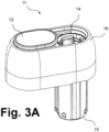
- Figures 3A to 3D show an extractor 11 as discussed before in an enlarged perspective view. More specifically, the extractor 11 is shown with the lid unit 12 in an open state corresponding to Figure 1B (see Figure 3A ) and a closed state corresponding to Figure 1A (see Figure 3B ).
- Figure 3C shows the extractor 11 with the lid unit 12 removed to expose the underlying components, i.e., a guiding arrangement configured to guide the lid unit 12 when slid between the positions shown in Figures 3A and 3B , which are referred to as a "first" and a "second" position herein, and in these positions.
- the guiding arrangement includes the flat base 13 already shown in Figure 1A , which extends in a plane, and lifting structures in the form of protrusions 18 arranged at edges of the base 13 parallel to the sliding direction.
- the protrusions 18 protrude from the base 13 in the proximal direction according to the definition given above and are configured to lift a part of the lid unit 12 in the first position and in the second position.
- the lifting structures 18 are arranged at central sections of two edges of the base 13, as further illustrated and explained below.
- protrusions 18 already mentioned or additional or alternative protrusions form guiding structures configured to at least one of lift and depress at least a part of the lid unit 12 when the lid unit 12 is in the first position and in the second position or moved therebetween
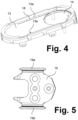
- Figure 4 shows an enlarged perspective view of a base subunit of the extractor 11 comprising the base 13 which was already shown before
- Figure 5 shows an enlarged top view of a lid carrier sled 19 which may form part of the lid unit 12
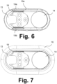
- Figure 6 shows an enlarged combined top view of the lid carrier sled 19 shown in Figure 5 and the base subunit shown in Figure 4
- Figure 7 shows an enlarged combined top view of the lid carrier sled 19 shown in Figure 5
- the base 13 of the lid guiding arrangement shown in Figure 4 and the covering unit 16 shown before
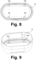
- Figure 8 shows an enlarged bottom view of the covering unit 16
- Figure 9 shows an enlarged perspective view of the covering unit 16.
- Figures 4 to 9 will be described together and the same reference numerals as above will be used further, wherein certain reference numerals will, for reasons of clarity, be used in certain Figures only without thereby indicating that corresponding elements are not present in the other Figures as well.
- the views of Figures 4 to 7 are from above, i.e. from a viewing point which would be at the top of Figures 1A to 1C , or "a user view” which a user would have from the device 10 when using the device 10
- the views of Figures 8 and 9 are from below, i.e. from a viewing point which would be at the bottom of Figures 1A to 1C , or a "device view" from the device towards the user of the device 10.
- the protrusions 18 protruding from the base 13 may be arranged at opposite edges 13a and 13b of the base 13 extending in parallel to a sliding direction of lid unit 12.
- the lid carrier sled 19 shown in Figure 5 in particular is configured to carry a sled cover which is exposed to a user, and may include structures configured to carry holding means such as magnets and the like. Skids 19a and 19b are part of the lid carrier sled 19 which are configured to mate with corresponding grooves formed between the base 13 and the covering unit 16 when they are brought into an operational configuration such as shown in Figures 7 and 8 .
- the lid carrier sled 19, and therefore the lid unit 12 as a whole is partly lifted when slid along the sliding direction between the first and second position, so that the unwanted tilting shown in Figures 2B, 2C, 2E and 2F is avoided.
- the covering unit 16 may comprise depressing structures, i.e. protrusions 16a to 16d, which may be formed as integral parts of the covering unit 16, and which serve to depress a part of the lid unit 12 to closely attach to the base 13 in the first and second position.
- depressing structures i.e. protrusions 16a to 16d, which may be formed as integral parts of the covering unit 16, and which serve to depress a part of the lid unit 12 to closely attach to the base 13 in the first and second position.
- Figures 10A to 10C show side views of certain elements of an aerosol provision device in a schematized manner, where the covering unit is partly illustrated and indicated, as above, with 16, and certain protrusions are indicated with 16a, 16b, and 18 as discussed in more detail in connection with the preceding Figures and one of the skids of the carrier sled 19 is indicated 19a.
- the protrusions 18 comprise sections 18a and 18b of opposite slopes, with or without an intermediate section 18c parallel to the plane of the base 13 or the lid unit 12.
- the protrusions 18 may be provided in a curved or straight shape in a sectional view orthogonal to the plane of the base 13.
- first protrusions in the form of protrusions 16a and 16b spaced apart by a protrusion distance are arranged at the covering unit 16 and second protrusions 18 comprising a maximum height at a position within the protrusion distance may be arranged at the base, and between these protrusions 16a, 16b and 18 the lid unit 12 or skids 19a are provided.
- Figures 11A to 11C show side views of certain elements of an aerosol provision device in a schematized manner, similarly to the views shown in Figures 10A to 10C .
- the covering unit 16 is provided without protrusions, but the lid unit 12, or the skids 19a, are provided with such, as indicated with 12a and 12b.
- a similar effect as above can be provided in this way, which comprises that guiding structures are generated including the protrusions 12a, 12b and 18, which are configured to at least one of lift and depress at least a part of the lid unit 12 when the lid unit 12 is in the first position and in the second position and or moved therebetween.
- Figures 12A to 12C show side views of certain elements of an aerosol provision device in a schematized manner, similarly to the views shown in Figures 10A to 10C and particularly Figures 11A to 11C .
- the covering unit 16 is, as before, provided without protrusions, but the lid unit 12, or the skids 19a, are provided with such, as indicated with 12c and 12c, but at opposite faces of the lid unit 12, or the skids 19a as compared to the configurations shown in Figures 11A to 11C . Again, a similar effect as above can be provided in this way, which was repeatedly explained above.
- Figures 13A to 13C show side views of certain elements of an aerosol provision device in a schematized manner, similarly to the views shown in Figures 10A to 10C , more particularly Figures 11A to 11C , and specifically Figures 12A to 12C .
- the covering unit 16 is provided with protrusions which are, however, provided in a similar shape as discussed for protrusions 18 which are arranged at the base 13 according to the configurations shown in Figures 10A to 10C , 11A to 11C , and 12A to 12C .
- protrusions 18 which are arranged at the base 13 according to the configurations shown in Figures 10A to 10C , 11A to 11C , and 12A to 12C .
- Figures 17A and 17B show certain parts of the device 10 and the article 20 essentially shown in the previous Figures already in a drawn-apart view ( Figure 17A ) and in an assembled view ( Figure 17B ).
- the pin-shaped element 125a protrudes from a main body of the device shown before into a chamber in which the receptacle 15 of the extractor 11 is received.
Landscapes
- Containers And Packaging Bodies Having A Special Means To Remove Contents (AREA)
Abstract
Aspects disclosed herein include an aerosol provision device (10) for generating aerosol from aerosol generating material, the device (10) comprising a receptacle (15) for receiving at least a portion of an article (20) comprising the aerosol generating material, the receptacle (15) comprising an opening (14) towards an outside of the device (10), a lid (12) configured to cover the opening (14) when in a first position and to allow access to the opening (14) when in a second position and slidable between the first position and the second position along a sliding direction, and a guiding arrangement configured to guide the lid (12) when slid between the first position and the second position, the arrangement comprising guiding structures configured to at least one of lift and depress at least a part of the lid unit (12) when the lid unit (12) is in the first position and in the second position and moved therebetween.
Description
- The present disclosure relates to the field of providing aerosols. In particular, the present disclosure relates to an aerosol provision device. The present disclosure also relates to an aerosol provision system and to a method of generating an aerosol.
- Smoking items such as cigarettes, cigars and the like traditionally burn tobacco during use, producing tobacco smoke. Efforts are being made to create alternatives to such items. In this regard, it may be envisaged in particular to heat, but not burn, a suitable material to release certain compounds, particularly in an inhalable aerosol. A suitable material may or may not contain tobacco and may or may not contain nicotine. Such a material may, e.g., be provided in a cylindrical unit or, more generally, an article comprising an aerosol generating material.
- According to an aspect, there is provided an aerosol provision device for generating aerosol from aerosol generating material, the device comprising:
- a receptacle for receiving at least a portion of an article comprising the aerosol generating material, the receptacle comprising an opening towards an outside of the device;
- a lid unit configured to cover the opening when in a first position and to allow access to the opening when in a second position, and slidable between the first position and the second position along a sliding direction; and
- a guiding arrangement configured to guide the lid unit when slid between the first position and the second position, the guiding arrangement comprising:
guiding structures configured to at least one of lift and depress at least a part of the lid unit when the lid unit is in at least one of the first position and the second position and moved between the first position and the second position. - In an embodiment of any of the above, the guiding arrangement may comprise a flat base extending in a plane and a covering unit, wherein the lid unit comprises structures engaging in a groove formed between the flat base and the covering unit.
- In an embodiment of any of the above, the guiding structures may comprise at least one of protrusions arranged at the flat base, protrusions arranged at the covering unit, and protrusions arranged at the lid unit.
- In an embodiment of any of the above, the lifting protrusions may comprise sections of opposite slopes.
- In an embodiment of any of the above, a flat section between said sections of opposite slopes and particularly parallel to a surface of the lid unit may be provided.
- In an embodiment of any of the above, the protrusions may be provided in a curved or straight shape in a sectional view, wherein the sectional view is in particular a sectional view in a plane orthogonal to a surface of the lid unit and parallel to the sliding direction.
- In an embodiment of any of the above, the protrusions may protrude 0.01 to 0.5 mm, 0.025 to 0.075 or about 0.05 mm from adjacent regions parallel to a surface of the lid unit.
- In an embodiment of any of the above, the protrusions may be formed integrally with or separately from a material of adjacent regions.
- In an embodiment of any of the above, first protrusions spaced apart by a protrusion distance may be arranged at the covering unit along the sliding direction and second protrusions comprising a maximum height at a position corresponding to a position within the protrusion distance may be arranged at the base, or vice versa, wherein skids of the lid unit are interposed between the first protrusions and the second protrusions.
- In an embodiment of any of the above, the protrusions may be arranged at opposite ends or central positions at least one of the base, the covering unit, and the lid unit.
- According to a further aspect, a system comprising a device according to any possible embodiment disclosed herein and an article including the aerosol generating material is also provided.
- According to a further aspect, there is provided a method of generating an aerosol, including providing an aerosol provision system as indicated above; and operating the aerosol provision system.
- Various embodiments will now be described, by way of example only, and with reference to the accompanying drawings, in which:
-
Figure 1A to 1C show perspective views of an aerosol provision device in three different operational configurations; -
Figures 2A to 2F show desired and undesired lid unit positions of the aerosol provision device shown inFigures 1A to 1C ; -
Figures 3A to 3C show enlarged perspective views of a top unit of the aerosol provision device as shown inFigures 1A to 1C ; -
Figure 4 shows an enlarged perspective view of a base of a lid unit guiding arrangement of the aerosol provision device shown inFigures 1A to 1C ; -
Figure 5 shows an enlarged top view of a lid carrier sled of the aerosol provision device shown inFigures 1A to 1C ; -
Figure 6 shows an enlarged combined view of the lid carrier sled shown inFigure 5 and the base of the lid unit guiding arrangement shown inFigure 4 ; -
Figure 7 shows an enlarged top view of the lid carrier sled shown inFigure 5 , the base of the lid unit guiding arrangement shown inFigure 4 , and a covering unit; -
Figure 8 shows an enlarged bottom view of the cover shown inFigure 7 ; -
Figure 9 shows an enlarged perspective view of the cover shown inFigure 8 ; -
Figures 10A to 10C show schematic side views of certain elements of an aerosol provision device; -
Figures 11A to 11C show schematic side views of certain elements of an aerosol provision device; -
Figures 12A to 12C show schematic side views of certain elements of an aerosol provision device; -
Figures 13A to 13C show schematic side views of certain elements of an aerosol provision device; -
Figures 14A to 14C show schematic side views of certain elements of an aerosol provision device; -
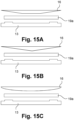
Figures 15A to 15C show schematic side views of certain elements of an aerosol provision device; -
Figures 16A to 16C show schematic side views of certain elements of an aerosol provision device; and -
Figures 17A and17B show side views of certain parts of an aerosol provision device illustrated in the previous Figures. - As used herein, the term "aerosol-generating material" is a material that is capable of generating aerosol, for example when heated, irradiated or energized in any other way. Aerosol-generating material may, for example, be in the form of a solid, liquid or gel which may or may not contain an active substance and/or flavourants. Aerosol-generating material may include any plant based material, such as tobacco-containing material and may, for example, include one or more of tobacco, tobacco derivatives, expanded tobacco, reconstituted tobacco or tobacco substitutes. Aerosol-generating material also may include other, non-tobacco, products, which, depending on the product, may or may not contain nicotine. Aerosol-generating material may for example be in the form of a solid, a liquid, a gel, a wax or the like. Aerosol-generating material may for example also be a combination or a blend of materials. Aerosol-generating material may also be known as "smokable material".
- The aerosol-generating material may comprise a binder and an aerosol former. Optionally, an active and/or filler may also be present. Optionally, a solvent, such as water, is also present and one or more other components of the aerosol-generating material may or may not be soluble in the solvent. In some embodiments, the aerosol-generating material is substantially free from botanical material. In some embodiments, the aerosol-generating material is substantially tobacco free.
- The aerosol-generating material may comprise or be an "amorphous solid". The amorphous solid may be a "monolithic solid". In some embodiments, the amorphous solid may be a dried gel. The amorphous solid is a solid material that may retain some fluid, such as liquid, within it. In some embodiments, the aerosol-generating material may, for example, comprise from about 50wt%, 60wt% or 70wt% of amorphous solid, to about 90wt%, 95wt% or 100wt% of amorphous solid.
- The aerosol-generating material may comprise an aerosol-generating film. The aerosol-generating film may comprise or be a sheet, which may optionally be shredded to form a shredded sheet. The aerosol-generating sheet or shredded sheet may be substantially tobacco free.
- According to the present disclosure, a "non-combustible" aerosol provision system is one where a constituent aerosol-generating material of the aerosol provision system (or component thereof) is not combusted or burned in order to facilitate delivery of at least one substance to a user.
- In some embodiments, the delivery system is a non-combustible aerosol provision system, such as a powered non-combustible aerosol provision system.
- In some embodiments, the non-combustible aerosol provision system is an electronic cigarette, also known as a vaping device or electronic nicotine delivery system (END), although it is noted that the presence of nicotine in the aerosol-generating material is not a requirement.
- In some embodiments, the non-combustible aerosol provision system is an aerosol-generating material heating system, also known as a heat-not-burn system. An example of such a system is a tobacco heating system.
- In some embodiments, the non-combustible aerosol provision system is a hybrid system to generate aerosol using a combination of aerosol-generating materials, one or a plurality of which may be heated. Each of the aerosol-generating materials may be, for example, in the form of a solid, liquid or gel and may or may not contain nicotine. In some embodiments, the hybrid system comprises a liquid or gel aerosol-generating material and a solid aerosol-generating material. The solid aerosol-generating material may comprise, for example, tobacco or a non-tobacco product.
- Typically, the non-combustible aerosol provision system may comprise a non-combustible aerosol provision device and a consumable for use with the non-combustible aerosol provision device.
- In some embodiments, the disclosure relates to consumables comprising aerosol-generating material and configured to be used with non-combustible aerosol provision devices. These consumables are sometimes referred to as articles throughout the disclosure.
- In some embodiments, the non-combustible aerosol provision system, such as a non-combustible aerosol provision device thereof, may comprise a power source and a controller. The power source may, for example, be an electric power source or an exothermic power source. In some embodiments, the exothermic power source comprises a carbon substrate which may be energised so as to distribute power in the form of heat to an aerosol-generating material or to a heat transfer material in proximity to the exothermic power source.
- In some embodiments, the non-combustible aerosol provision system may comprise an area for receiving the consumable, an aerosol generator, an aerosol generation area, a housing, a mouthpiece, a filter and/or an aerosol-modifying agent.
- In some embodiments, the consumable for use with the non-combustible aerosol provision device may comprise aerosol-generating material, an aerosol-generating material storage area, an aerosol-generating material transfer component, an aerosol generator, an aerosol generation area, a housing, a wrapper, a filter, a mouthpiece, and/or an aerosol-modifying agent.
- An aerosol generating device can receive an article comprising aerosol generating material for heating. An "article" in this context is a component that includes or contains in use the aerosol generating material, which is heated to volatilise the aerosol generating material, and optionally other components in use. A user may insert the article into the aerosol generating device before it is heated to produce an aerosol, which the user subsequently inhales. The article may be, for example, of a predetermined or specific size that is configured to be placed within a heating chamber of the device which is sized to receive the article.
-
Figures 1A to 1C show perspective views of anaerosol provision device 10 in three different operational configurations, wherein an "operational configuration" may result from at least one of certain components ofdevice 10 being operated by a user or an article being inserted into thedevice 10. - In
Figures 1A to 1C , like reference numerals indicate the same, essentially the same, functionally identical, or similar components and will be described together hereinbelow. Repeated explanations are omitted for reasons of conciseness. - The
aerosol provision device 10 is configured to generate aerosol from an aerosol generating article, which is not shown inFigures 1A and1B and which is shown and referred to withreference numeral 20 inFigure 1C . - The
aerosol provision device 10 is an elongate structure, extending along a longitudinal axis. Theaerosol provision device 10 has aproximal end 10a, which will be closest to the user (e.g. the user's mouth) when in use by the user to inhale the aerosol generated by theaerosol provision device 10, as well as adistal end 10b which will be furthest from the user when in use. Theproximal end 10a may also be referred to as the "mouth end" or "top end". As further explained below, theproximal end 10a of theaerosol provision device 10 is formed by a top unit, also referred to as an "extractor" 11. - The
aerosol generating article 20 may be inserted, in use, into theaerosol provision device 10. For this purpose, theaerosol provision device 10 comprises anopening 14 to a receptacle discussed below, as shown inFigure 1B , into which theaerosol generating article 20 may be inserted, and which is provided as a heating chamber which is not fully shown for reasons of clarity. In certain embodiments, or theaerosol provision device 10 and thearticle 20 may be understood as parts of an aerosol generating system as referred to withreference numeral 100 inFigure 1C . - The
aerosol provision device 10 also accordingly defines a proximal direction, which is directed towards the user when in use. Further, theaerosol provision device 10 also likewise defines a distal direction, which is directed away from the user when in use. The terms proximal and distal as applied to features of thedevice 10 will be described by reference to the relative positioning of such features with respect to each other in a proximal-distal direction along a longitudinal axis which is not shown for reasons of conciseness. - The
aerosol provision device 10 includes aslidable lid unit 12. When theaerosol provision device 10 is not in use, theslidable lid unit 12 may be closed so as to cover theopening 14 to the receptacle of theaerosol provision device 10 as shown inFigure 1A . Theslidable lid unit 12 may be held in certain positions by magnets associated with thelid unit 12 and/or a body of thedevice 10 beneath thelid unit 12. As shown inFigures 1B and1C , thelid unit 12 may be opened to provide access to theopening 14 to the receptacle, and theextractor 11 comprises a generallyflat base 13 extending in a plane. - One or more user-
operable control elements 17, such as buttons, sliders or the like which can be used to operate theaerosol provision device 10, may be provided on a side of theaerosol provision device 10. -
Figures 2A to 2F show desired and undesired positions oflid unit 12 in theaerosol provision device 10 shown inFigures 1A to 1C . More specifically, theextractor 11 already shown above is shown in each ofFigures 2A to 2F in a state being removed from the rest of the elements of theaerosol provision device 10. As visible fromFigures 2A to 2F , the receptacle mentioned above is formed by a peripheral wall and referred to withreference numeral 15. Thereceptacle 15 is an integral part of theextractor 11, into which anarticle 20 can be introduced to be heated. A cap part, also referred to as coveringunit 16 at other places herein, is also part of theextractor 11, as well as further parts described below. -
Figures 2A and 2D show desired positions of thelid unit 12 in an open state corresponding toFigure 1B (seeFigure 2A ) and a closed state corresponding toFigure 1A (seeFigure 2D ). In these desired positions, thelid unit 12, i.e. an upper surface thereof, is arranged essentially parallel to the upper surface of theextractor 11. In contrast, inFigures 2B, 2C, 2E and 2F show undesired positions in which thelid unit 12 is tilted. This is disadvantageous particularly because items, e.g., in a pocket of a user, such as keys, handkerchiefs, parts of a wallet or cloth may get under the lid, lift it up, and in a worst case tear it off. - Embodiments as disclosed herein solve these problems as indicated below by providing a guiding structure in which parts of the
lid unit 12 may be lifted to avoid tilting as shown before. -
Figures 3A to 3D show anextractor 11 as discussed before in an enlarged perspective view. More specifically, theextractor 11 is shown with thelid unit 12 in an open state corresponding toFigure 1B (seeFigure 3A ) and a closed state corresponding toFigure 1A (seeFigure 3B ).Figure 3C shows theextractor 11 with thelid unit 12 removed to expose the underlying components, i.e., a guiding arrangement configured to guide thelid unit 12 when slid between the positions shown inFigures 3A and3B , which are referred to as a "first" and a "second" position herein, and in these positions. - As particularly seen in
Figures 3B and3C , the guiding arrangement includes theflat base 13 already shown inFigure 1A , which extends in a plane, and lifting structures in the form ofprotrusions 18 arranged at edges of the base 13 parallel to the sliding direction. Of theprotrusions 18, only oneprotrusion 18 is visible inFigures 3B and3C while the other is hidden by a rim of coveringstructure 16. Theprotrusions 18 protrude from the base 13 in the proximal direction according to the definition given above and are configured to lift a part of thelid unit 12 in the first position and in the second position. The liftingstructures 18 are arranged at central sections of two edges of thebase 13, as further illustrated and explained below. - Certain elements of
extractor 11 are further illustrated below, and details and functions of certain parts are explained. As discussed, using theprotrusions 18 already mentioned or additional or alternative protrusions form guiding structures configured to at least one of lift and depress at least a part of thelid unit 12 when thelid unit 12 is in the first position and in the second position or moved therebetween - In this connection, and for this purpose,
Figure 4 shows an enlarged perspective view of a base subunit of theextractor 11 comprising the base 13 which was already shown before,Figure 5 shows an enlarged top view of alid carrier sled 19 which may form part of thelid unit 12,Figure 6 shows an enlarged combined top view of thelid carrier sled 19 shown inFigure 5 and the base subunit shown inFigure 4 ,Figure 7 shows an enlarged combined top view of thelid carrier sled 19 shown inFigure 5 , thebase 13 of the lid guiding arrangement shown inFigure 4 , and the coveringunit 16 shown before,Figure 8 shows an enlarged bottom view of the coveringunit 16, andFigure 9 shows an enlarged perspective view of the coveringunit 16. -
Figures 4 to 9 will be described together and the same reference numerals as above will be used further, wherein certain reference numerals will, for reasons of clarity, be used in certain Figures only without thereby indicating that corresponding elements are not present in the other Figures as well. It should be noted that the views ofFigures 4 to 7 are from above, i.e. from a viewing point which would be at the top ofFigures 1A to 1C , or "a user view" which a user would have from thedevice 10 when using thedevice 10, and the views ofFigures 8 and 9 are from below, i.e. from a viewing point which would be at the bottom ofFigures 1A to 1C , or a "device view" from the device towards the user of thedevice 10. - As can be seen from
Figure 4 , similarly toFigures 3A to 3C , theprotrusions 18 protruding from the base 13 may be arranged atopposite edges lid unit 12. Thelid carrier sled 19 shown inFigure 5 in particular is configured to carry a sled cover which is exposed to a user, and may include structures configured to carry holding means such as magnets and the like.Skids lid carrier sled 19 which are configured to mate with corresponding grooves formed between the base 13 and the coveringunit 16 when they are brought into an operational configuration such as shown inFigures 7 and8 . As can clearly be seen from the Figures, thelid carrier sled 19, and therefore thelid unit 12 as a whole, is partly lifted when slid along the sliding direction between the first and second position, so that the unwanted tilting shown inFigures 2B, 2C, 2E and 2F is avoided. - As can be seen from
Figures 8 and 9 , the coveringunit 16, on the other hand, may comprise depressing structures, i.e. protrusions 16a to 16d, which may be formed as integral parts of the coveringunit 16, and which serve to depress a part of thelid unit 12 to closely attach to the base 13 in the first and second position. -
Figures 10A to 10C show side views of certain elements of an aerosol provision device in a schematized manner, where the covering unit is partly illustrated and indicated, as above, with 16, and certain protrusions are indicated with 16a, 16b, and 18 as discussed in more detail in connection with the preceding Figures and one of the skids of thecarrier sled 19 is indicated 19a. - As can be seen from
Figures 10A and 10B , theprotrusions 18 comprisesections intermediate section 18c parallel to the plane of the base 13 or thelid unit 12. In an alternative configuration shown inFigure 10C , theprotrusions 18 may be provided in a curved or straight shape in a sectional view orthogonal to the plane of thebase 13. - As shown in
Figures 10A to 10C , in other words, first protrusions in the form ofprotrusions unit 16 andsecond protrusions 18 comprising a maximum height at a position within the protrusion distance may be arranged at the base, and between theseprotrusions lid unit 12 orskids 19a are provided. -
Figures 11A to 11C show side views of certain elements of an aerosol provision device in a schematized manner, similarly to the views shown inFigures 10A to 10C . - As shown in
Figures 11A to 11C , the coveringunit 16 is provided without protrusions, but thelid unit 12, or theskids 19a, are provided with such, as indicated with 12a and 12b. A similar effect as above can be provided in this way, which comprises that guiding structures are generated including theprotrusions lid unit 12 when thelid unit 12 is in the first position and in the second position and or moved therebetween. - Also
Figures 12A to 12C show side views of certain elements of an aerosol provision device in a schematized manner, similarly to the views shown inFigures 10A to 10C and particularlyFigures 11A to 11C . - As shown in
Figures 12A to 12C , the coveringunit 16 is, as before, provided without protrusions, but thelid unit 12, or theskids 19a, are provided with such, as indicated with 12c and 12c, but at opposite faces of thelid unit 12, or theskids 19a as compared to the configurations shown inFigures 11A to 11C . Again, a similar effect as above can be provided in this way, which was repeatedly explained above. -
Figures 13A to 13C show side views of certain elements of an aerosol provision device in a schematized manner, similarly to the views shown inFigures 10A to 10C , more particularlyFigures 11A to 11C , and specificallyFigures 12A to 12C . - As shown in
Figures 13A to 13C , the coveringunit 16 is provided with protrusions which are, however, provided in a similar shape as discussed forprotrusions 18 which are arranged at the base 13 according to the configurations shown inFigures 10A to 10C ,11A to 11C , and12A to 12C . As to further details and effects, reference is made to the explanations above regardingFigures 10A to 10C ,11A to 11C , and12A to 12C . - Further configurations are shown in
Figures 14A to 14C ,15A to 15C , and16A to 16C wherein essentially the same explanations as to the previousFigures 10A to 10C ,11A to 11C ,12A to 12C , and13A to 13C , apply. Further explanations are omitted for reasons of conciseness. -
Figures 17A and17B show certain parts of thedevice 10 and thearticle 20 essentially shown in the previous Figures already in a drawn-apart view (Figure 17A ) and in an assembled view (Figure 17B ). Theextractor 11, which is shown here again, forms part of a removal mechanism which is used to aid extraction of thearticle 20 by pulling the article off aheater 125, or, more specifically, a pin-shapedpart 125a thereof in a reliable way. The pin-shapedelement 125a protrudes from a main body of the device shown before into a chamber in which thereceptacle 15 of theextractor 11 is received. The pin upstands in theextractor 11 through a hole in the base of thereceptacle 15, as becomes clear in a synoptic view ofFigures 17A and17B . - The various embodiments described herein are presented only to assist in understanding and teaching the claimed features. These embodiments are provided as a representative sample of embodiments only, and are not exhaustive and/or exclusive. It is to be understood that advantages, embodiments, examples, functions, features, structures, and/or other aspects described herein are not to be considered limitations on the scope of the invention as defined by the claims or limitations on equivalents to the claims, and that other embodiments may be utilised and modifications may be made without departing from the scope of the claimed invention. Various embodiments of the invention may suitably comprise, consist of, or consist essentially of, appropriate combinations of the disclosed elements, components, features, parts, steps, means, etc, other than those specifically described herein. In addition, this disclosure may include other inventions not presently claimed, but which may be claimed in future.
Claims (14)
- An aerosol provision device for generating aerosol from aerosol generating material, the aerosol provision device comprising:a receptacle configured to receive at least a portion of an article comprising the aerosol generating material, the receptacle comprising an opening;a lid unit configured to cover the opening when in a first position and to allow access to the opening when in a second position, and slidable between the first position and the second position along a sliding direction; anda guiding arrangement configured to guide the lid when slid between the first position and the second position, at least one of the guiding arrangement and the lid unit comprising:
guiding structures configured to at least one of lift and depress at least a part of the lid unit when the lid unit is in the first position and in the second position or moved therebetween. - The device according to claim 1, wherein the guiding arrangement comprises a flat base extending in a plane and a covering unit, wherein the lid unit comprising structures engaging in a groove formed between the flat base and the covering unit.
- The device according to claim 1 or 2, wherein the guiding structures comprise at least one of protrusions arranged at central sections of two edges of the base extending in parallel to the sliding direction and protrusions arranged at the covering unit.
- The device according to claim 3, wherein the protrusions comprise sections of opposite slopes.
- The device according to claim 4, wherein a flat section parallel between said sections of opposite slopes sections is provided.
- The device according to claim 3, wherein the protrusions are provided in a curved or straight shape in a sectional view.
- The device according to any one of claims 1 to 6, wherein the lifting structures protrude 0.01 to 0.5 mm, 0.025 to 0.075 or about 0.05 mm from adjacent regions.
- The device according to any one of claims 3 to 7, wherein the protrusions are formed integrally with or separately from a material of adjacent regions.
- The device according to any one of claims 3 to 8, wherein first protrusions spaced apart by a protrusion distance are arranged at the covering unit and second protrusions comprising a maximum height at a position within the protrusion distance are arranged at the base or vice versa, wherein skids of the lid unit are interposed between the first protrusions and the second protrusions.
- The device according to any one of claims 3 to 9, wherein the protrusions are arranged at opposite ends or central positions of at least one of the base, the covering unit, and the lid unit.
- The device according to any one of the preceding claims, wherein the protrusions exert opposite forces at different positions to the lid unit from above and below the lid unit.
- The device according to any one of claims 2 to 11, wherein skids are provided at the lid unit and are configured to mate with the groove formed between the flat base and the covering unit.
- An aerosol provision system comprising an aerosol provision device according to any of the preceding claims and an article including aerosol generating material.
- A method of generating an aerosol, including:providing an aerosol provision device or system according to any one of claims 1 to 13; andoperating the aerosol provision device or system.
Priority Applications (1)
| Application Number | Priority Date | Filing Date | Title |
|---|---|---|---|
| PCT/EP2024/086060 WO2025125505A1 (en) | 2023-12-13 | 2024-12-12 | Aerosol provision device |
Applications Claiming Priority (1)
| Application Number | Priority Date | Filing Date | Title |
|---|---|---|---|
| CN202311722675.2A CN120130697A (en) | 2023-12-13 | 2023-12-13 | Aerosol supply device |
Publications (1)
| Publication Number | Publication Date |
|---|---|
| EP4570086A1 true EP4570086A1 (en) | 2025-06-18 |
Family
ID=89722977
Family Applications (1)
| Application Number | Title | Priority Date | Filing Date |
|---|---|---|---|
| EP24154010.3A Pending EP4570086A1 (en) | 2023-12-13 | 2024-01-25 | Aerosol provision device |
Country Status (2)
| Country | Link |
|---|---|
| EP (1) | EP4570086A1 (en) |
| CN (1) | CN120130697A (en) |
Citations (3)
| Publication number | Priority date | Publication date | Assignee | Title |
|---|---|---|---|---|
| US20220142247A1 (en) * | 2019-05-03 | 2022-05-12 | Jt International S.A. | Aerosol Generation Device With Closure |
| US20220167681A1 (en) * | 2019-04-04 | 2022-06-02 | Nicoventures Trading Limited | Aerosol generating apparatus |
| EP4374719A1 (en) * | 2022-11-25 | 2024-05-29 | JT International S.A. | An aerosol generation device, and a method of opening an aerosol generation chamber thereof |
-
2023
- 2023-12-13 CN CN202311722675.2A patent/CN120130697A/en active Pending
-
2024
- 2024-01-25 EP EP24154010.3A patent/EP4570086A1/en active Pending
Patent Citations (3)
| Publication number | Priority date | Publication date | Assignee | Title |
|---|---|---|---|---|
| US20220167681A1 (en) * | 2019-04-04 | 2022-06-02 | Nicoventures Trading Limited | Aerosol generating apparatus |
| US20220142247A1 (en) * | 2019-05-03 | 2022-05-12 | Jt International S.A. | Aerosol Generation Device With Closure |
| EP4374719A1 (en) * | 2022-11-25 | 2024-05-29 | JT International S.A. | An aerosol generation device, and a method of opening an aerosol generation chamber thereof |
Also Published As
| Publication number | Publication date |
|---|---|
| CN120130697A (en) | 2025-06-13 |
Similar Documents
| Publication | Publication Date | Title |
|---|---|---|
| JP2019122393A (en) | Device for heating aerosol generation material | |
| KR20180107161A (en) | Flavor transfer device | |
| JP7578797B2 (en) | Aerosol Delivery Device | |
| KR20200085170A (en) | Micro particle generator | |
| JP7465352B2 (en) | Aerosol generating device with movable parts | |
| KR20240110637A (en) | Aerosol delivery device | |
| US20250261688A1 (en) | Aerosol Generating Device and Assembly, and Packaging Enabling Easy Grabbing of a Consumable Article | |
| WO2025125505A1 (en) | Aerosol provision device | |
| JP2024545319A (en) | Aerosol Delivery Device | |
| US20250057215A1 (en) | Aerosol provision device | |
| CN120130697A (en) | Aerosol supply device | |
| EP4287863B1 (en) | Non-combustible aerosol provision device | |
| EP4570089A1 (en) | Aerosol provision device | |
| EP4570088A1 (en) | Aerosol provision device | |
| US20260101934A1 (en) | Aerosol provision device comprising a user input element | |
| WO2024259608A1 (en) | Extractor element of an aerosol provision device | |
| EP4652878A1 (en) | Aerosol provision device | |
| WO2025125517A1 (en) | Aerosol provision device | |
| JP2024504773A (en) | Non-flammable aerosol delivery device | |
| WO2025125512A1 (en) | Aerosol provision system | |
| WO2024261087A2 (en) | Extractor element of an aerosol provision device | |
| EP4727383A1 (en) | Aerosol provision device | |
| WO2025125643A1 (en) | Aerosol provision device | |
| WO2025202464A1 (en) | Aerosol provision device | |
| JP2026515000A (en) | Aerosol generator equipped with airflow control valve |
Legal Events
| Date | Code | Title | Description |
|---|---|---|---|
| PUAI | Public reference made under article 153(3) epc to a published international application that has entered the european phase |
Free format text: ORIGINAL CODE: 0009012 |
|
| STAA | Information on the status of an ep patent application or granted ep patent |
Free format text: STATUS: THE APPLICATION HAS BEEN PUBLISHED |
|
| AK | Designated contracting states |
Kind code of ref document: A1 Designated state(s): AL AT BE BG CH CY CZ DE DK EE ES FI FR GB GR HR HU IE IS IT LI LT LU LV MC ME MK MT NL NO PL PT RO RS SE SI SK SM TR |
|
| P01 | Opt-out of the competence of the unified patent court (upc) registered |
Free format text: CASE NUMBER: UPC_APP_0010885_4570086/2025 Effective date: 20251023 |
|
| STAA | Information on the status of an ep patent application or granted ep patent |
Free format text: STATUS: THE APPLICATION IS DEEMED TO BE WITHDRAWN |