EP4570083A1 - A device for separating a multi-segment rod-like article of tobacco industry - Google Patents
A device for separating a multi-segment rod-like article of tobacco industry Download PDFInfo
- Publication number
- EP4570083A1 EP4570083A1 EP23215589.5A EP23215589A EP4570083A1 EP 4570083 A1 EP4570083 A1 EP 4570083A1 EP 23215589 A EP23215589 A EP 23215589A EP 4570083 A1 EP4570083 A1 EP 4570083A1
- Authority
- EP
- European Patent Office
- Prior art keywords
- conveyor
- groove
- segment
- article
- perforating
- Prior art date
- Legal status (The legal status is an assumption and is not a legal conclusion. Google has not performed a legal analysis and makes no representation as to the accuracy of the status listed.)
- Granted
Links
Images


Classifications
-
- A—HUMAN NECESSITIES
- A24—TOBACCO; CIGARS; CIGARETTES; SIMULATED SMOKING DEVICES; SMOKERS' REQUISITES
- A24C—MACHINES FOR MAKING CIGARS OR CIGARETTES
- A24C5/00—Making cigarettes; Making tipping materials for, or attaching filters or mouthpieces to, cigars or cigarettes
- A24C5/36—Removing papers or other parts from defective cigarettes
Definitions
- the present invention relates to a device for separating a multi-segment rod-like article of tobacco industry.
- tobacco industry products include, apart from tobacco, a variety of materials used to filter tobacco smoke or to impart flavor. Furthermore, inserts, such as metal inserts, are utilized to heat tobacco or tobacco-based material.
- German patent DE1204118 discloses a device for continuously opening wrapper tissue paper on successive axially fed cigarettes by means of toothed disc knives.
- a device for cutting the wrapper paper of axially fed cigarettes is known from patent EP2364605 .
- a device for perforating multiple cigarettes simultaneously is known from patent PL204696 .
- devices for recovering single segments from rod-like articles and for perforating such single segments are not known.
- the object of the invention is a separating device for separating a multi-segment rod-like article of tobacco industry comprising segments wrapped with a wrapper material, the device comprising: a first conveyor for conveying multi-segment rod-like articles and having first grooves; a second conveyor for conveying separated segments after separation of the multi-segment rod-like article, having second grooves; wherein the first conveyor and the second conveyor are positioned so that a first movement track of the first groove and a second movement track of the second groove intersect; wherein the first conveyor and the second conveyor are synchronized such that in an intersection zone of said movement tracks, the first groove is positioned opposite the second groove so that the first groove and the second groove push adjacent segments in opposite directions.
- the device further comprises a perforating device for perforating and/or incising the wrapper material of the separated segment.
- the perforating device can be configured to perforate and/or incise the wrapper material of the separated segment transported in the second groove on the second conveyor.
- the perforating device may have a form of a rotating roller with needles.
- the perforating device may have a form of a rotating roller with knives.
- the rotation axis of the roller can be located parallel to the rotation axis of the perforating device.
- the first conveyor may have a form of a chain conveyor.
- the first conveyor may have a form of a rotary drum conveyor.
- the device may further comprise a positioning unit for correcting the position of the multi-segment rod-like article in the first groove in a direction transverse to the direction of movement of the first groove.
- the device may further comprise a feeder for placing the multi-segment rod-like article on the first conveyor.
- the invention also relates to a method for separating a multi-segment rod-like article of tobacco industry comprising segments wrapped with a wrapper, the method comprising the steps of: transferring the multi-segment rod-like article in a first groove of a first conveyor along a first movement track, rotating a second conveyor so that a second groove of the second conveyor moves along a second movement track such that the first movement track of the first groove and the multi-segment rod-like article and the second movement track of the second groove intersect, pressing adjacent segments in opposite directions in the intersection zone of said movement tracks, moving a separated segment of the multi-segment rod-like article in the second groove of the second conveyor to a perforating device.
- the method comprises perforating and/or incising the wrapper material of the separated segment moved in the second groove of the second conveyor with the perforating device.
- the device for separating a multi-segment rod-like article according to the invention is compact, simple, and inexpensive to manufacture.
- Fig. 1 shows a first embodiment of a separating device 1 for separating a multi-segment rod-like article 2 of tobacco industry into fragments.
- the exemplary multi-segment rod-like article 2 shown in Fig. 2 comprises four segments 2A, 2B, 2C, 2D wrapped with a wrapper material 2X.
- the multi-segment rod-like article 2 comprises at least two segments, but the number of segments can be arbitrary.
- the separating device 1 comprises a separating unit 3 with two movable elements that separate the multi-segment rod-like article 2 into parts.
- the separating unit 3 comprises a first conveyor 4 for transporting the multi-segment rod-like article 2 and a second conveyor 6 for transporting the separated segments 2B.
- the first conveyor 4 is provided with first grooves 5.
- the first conveyor 4 can have a form of a chain conveyor, a disc conveyor or a drum conveyor with the first grooves 5 located on its periphery.
- the first grooves 5 serve as transporting grooves for the rod-like articles 2.
- the second conveyor 6 is provided with second grooves 7, which serve as transporting grooves for conveying the separated segments 2B.
- the first conveyor 4 and the second conveyor 6 are synchronized so that the first grooves 5 and the second grooves 7 move coincidentally.
- the drawing shows a first movement track 5T of the first groove 5 and a second movement track 7T of the second groove 7, wherein the first movement track 5T and the second movement track 7T intersect at an intersection zone X.
- the first movement track 5T of the first groove 5 represents the track of movement of the conveyed multi-segment rod-like article 2.
- the first conveyor 4 and the second conveyor 6 are synchronized so that the first groove 5 aligns directly opposite the second groove 7.
- adjacent segments in the multi-segment rod-like article 2 are pressed in opposite directions, causing the segments to separate.
- segment 2A and segment 2B are pressed in opposite directions PA and PB.
- segments 2B and 2C are pressed in opposite directions PB and PC.
- the pressure on adjacent segments causes segments 2A, 2B, 2C to separate, and the wrapper material 2X within the boundary between segments 2A and 2B breaks apart, similarly, the wrapper material 2X within the boundary between segments 2B and 2C breaks apart.
- Segments 2A and 2C are carried and supported in the first groove 5 of the first conveyor 4, and segment 2B is carried and supported in the second groove 7 of the second conveyor 6. After separation, segment 2B remains in the second groove 7, whereby segment 2B can be held by a guide 23.
- the separated segment 2B is then subjected to a perforating device.
- the separated segments 2B can be received from the conveyor 6 and transferred to a perforating device not directly located at the conveyor 6.
- the perforating device 9 is located directly at the second conveyor 6. Segment 2B remains in the groove 7 and is transferred to the perforating location.
- the perforating device 9 is configured to incise or perforate the wrapper material 2X of the separated segment 2B to facilitate the extraction of the filler material from inside the separated segment 2B.
- the perforating device 9 shown in Fig. 4 is configured to perforate the wrapper material 2X of the separated segment 2B transported in the second groove 7 by means of needles 10 arranged in rows 12 on the peripheral surface of a roller 11.
- Successive rows 12 of needles 10 perforate successive separated segments 2B.
- the rows 12 are arranged parallel to the rotation axis k of the perforating device 9.
- the use of needles is particularly recommended for a hard wrapper material that is difficult to incise. Needles with a large taper angle can be used to ensure that the holes formed in the wrapper material after puncturing are enlarged equally in each direction, thereby preventing the segment from being displaced during perforation.
- Fig. 5 shows a second embodiment of the perforating device 9', wherein triangular-shaped knives 13 are used for perforation.
- the shape of the knife is an isosceles triangle or a non-isosceles triangle.
- the knives 13 rotate with the roller 11 and perforate the wrapper material 2X, and then as the roller 11 continues to rotate, the knives 13 plunge into the segment 2B and cut the wrapper material 2X. It is possible to use a single wide knife 13 having a width of the roller 11 or several narrower knives.
- the forces created when the triangular-shaped knife plunges into the segment are directed in opposite directions, offsetting each other out and preventing the segment from moving when the wrapper is cut.
- Perforating devices equipped with knives with different angles of inclination can be used, depending on the strength of the wrapper material.
- Fig. 6 shows an embodiment of a perforating device 9' using knives 13' with blades 21 and curved cutting edges 22.
- the blades 21 produce maximum unit pressure on the wrapper material 2X, facilitating perforation, after which the wrapper material 2X is cut by the cutting edges 22.
- This shape of the knives 13' is suitable for a strong, hard wrapper material 2X.
- the perforating device 9, 9', 9" perforates and cuts the wrapper material 2X to weaken the wrapper material 2X sectionally, making it easier to completely tear the wrapper material 2X and extract the filler material in the next step of the recovery process.
- a separating device 1' is presented wherein the rod-like articles 2 are conveyed on a first conveyor 4 in the form of a drum with first grooves 5.
- the separating device 1' is provided with a positioning unit 14 for adjusting the position of the multi-segment rod-like article 2 in the first groove 5 in a direction transverse to the direction of movement of the first conveying groove 5, i.e. axially along the axis of groove 5 so that only the segments 2B are pressed by the second grooves 7 of the second conveyor 6.
- the positioning unit 14 comprises a stop bar 15 and nozzles 16 that supply compressed air to press the articles 2 against the stop bar 15.
- the separated segment 2B is conveyed to the perforating device 9' and held in the second groove 7 by means of a vacuum supplied through holes 24 in the second groove 7.
- the rotation axis k of the perforating device 9', the rotation axis m of the second conveyor 6 and the rotation axis n of the first conveyor 5 are parallel to each other.
- a row 12 of knives 13 in the perforating device 9' is located parallel to the rotation axis k.
- the segment 2B is cylindrical, and the knives 13 perforate along the generatix of this cylinder, with the perforation being performed on the side opposite the holding area of the segment 2B by means of a vacuum.
- the separating device 1 comprises a feeder 17 for placing the multi-segment rod-like article 2 on the first conveyor 4 as shown in Fig. 1 .
- the multi-segment rod-like article 2 can be fed transversely to the axis of the article 2 as well as in line with the axis of the article 2.
- the separating device 1 is provided with a container 18 for the separated segments 2B and containers 19, 20 for the remaining separated segments 2A, 2C, 2D.
Landscapes
- Cigarettes, Filters, And Manufacturing Of Filters (AREA)
Abstract
Description
- The present invention relates to a device for separating a multi-segment rod-like article of tobacco industry.
- Currently, tobacco industry products include, apart from tobacco, a variety of materials used to filter tobacco smoke or to impart flavor. Furthermore, inserts, such as metal inserts, are utilized to heat tobacco or tobacco-based material.
- Since the onset of mass production of cigarettes, the recovery of tobacco from defective cigarettes has been a significant issue. The recovery of tobacco or other materials used in the smoking article remains important today, with some materials being sorted and recovered solely for disposal.
- In the current state of the art, there are known devices for making perforations along rod-like articles. A German patent
DE1204118 discloses a device for continuously opening wrapper tissue paper on successive axially fed cigarettes by means of toothed disc knives. A device for cutting the wrapper paper of axially fed cigarettes is known from patentEP2364605 . A device for perforating multiple cigarettes simultaneously is known from patentPL204696 - Therefore, there is a need to provide a device for separating a multi-segment rod-like article of tobacco industry that would be capable of recovering single segments from the article.
- The object of the invention is a separating device for separating a multi-segment rod-like article of tobacco industry comprising segments wrapped with a wrapper material, the device comprising: a first conveyor for conveying multi-segment rod-like articles and having first grooves; a second conveyor for conveying separated segments after separation of the multi-segment rod-like article, having second grooves; wherein the first conveyor and the second conveyor are positioned so that a first movement track of the first groove and a second movement track of the second groove intersect; wherein the first conveyor and the second conveyor are synchronized such that in an intersection zone of said movement tracks, the first groove is positioned opposite the second groove so that the first groove and the second groove push adjacent segments in opposite directions. The device further comprises a perforating device for perforating and/or incising the wrapper material of the separated segment.
- The perforating device can be configured to perforate and/or incise the wrapper material of the separated segment transported in the second groove on the second conveyor.
- The perforating device may have a form of a rotating roller with needles.
- The perforating device may have a form of a rotating roller with knives.
- The rotation axis of the roller can be located parallel to the rotation axis of the perforating device.
- The first conveyor may have a form of a chain conveyor.
- The first conveyor may have a form of a rotary drum conveyor.
- The device may further comprise a positioning unit for correcting the position of the multi-segment rod-like article in the first groove in a direction transverse to the direction of movement of the first groove.
- The device may further comprise a feeder for placing the multi-segment rod-like article on the first conveyor.
- The invention also relates to a method for separating a multi-segment rod-like article of tobacco industry comprising segments wrapped with a wrapper, the method comprising the steps of: transferring the multi-segment rod-like article in a first groove of a first conveyor along a first movement track, rotating a second conveyor so that a second groove of the second conveyor moves along a second movement track such that the first movement track of the first groove and the multi-segment rod-like article and the second movement track of the second groove intersect, pressing adjacent segments in opposite directions in the intersection zone of said movement tracks, moving a separated segment of the multi-segment rod-like article in the second groove of the second conveyor to a perforating device. The method comprises perforating and/or incising the wrapper material of the separated segment moved in the second groove of the second conveyor with the perforating device.
- The device for separating a multi-segment rod-like article according to the invention is compact, simple, and inexpensive to manufacture.
- The object of the invention is shown by means of example embodiments shown in a drawing, wherein:
-
Fig. 1 shows a first embodiment of a separating device, -
Fig. 2 shows an example of a rod-like article, -
Fig. 3 shows a cross-section of the separating device ofFig. 1 , -
Fig. 4 shows a first embodiment of a perforating device, -
Fig. 5 shows a second embodiment of the perforating device, -
Fig. 6 shows a third embodiment of the perforating device, -
Fig. 7 shows a first embodiment of the separating device. -
Fig. 1 shows a first embodiment of aseparating device 1 for separating a multi-segment rod-like article 2 of tobacco industry into fragments. The exemplary multi-segment rod-like article 2 shown inFig. 2 comprises foursegments wrapper material 2X. In the context of the present invention, the multi-segment rod-like article 2 comprises at least two segments, but the number of segments can be arbitrary. - The
separating device 1 comprises a separatingunit 3 with two movable elements that separate the multi-segment rod-like article 2 into parts. In the embodiment ofFig. 1 , theseparating unit 3 comprises afirst conveyor 4 for transporting the multi-segment rod-like article 2 and asecond conveyor 6 for transporting theseparated segments 2B. Thefirst conveyor 4 is provided withfirst grooves 5. Thefirst conveyor 4 can have a form of a chain conveyor, a disc conveyor or a drum conveyor with thefirst grooves 5 located on its periphery. Thefirst grooves 5 serve as transporting grooves for the rod-like articles 2. Thesecond conveyor 6 is provided withsecond grooves 7, which serve as transporting grooves for conveying theseparated segments 2B. Thefirst conveyor 4 and thesecond conveyor 6 are synchronized so that thefirst grooves 5 and thesecond grooves 7 move coincidentally. The drawing shows afirst movement track 5T of thefirst groove 5 and asecond movement track 7T of thesecond groove 7, wherein thefirst movement track 5T and thesecond movement track 7T intersect at an intersection zone X. Thefirst movement track 5T of thefirst groove 5 represents the track of movement of the conveyed multi-segment rod-like article 2. - The
first conveyor 4 and thesecond conveyor 6 are synchronized so that thefirst groove 5 aligns directly opposite thesecond groove 7. In the intersection zone X of thesetracks like article 2 are pressed in opposite directions, causing the segments to separate. As shown inFig. 3 ,segment 2A andsegment 2B are pressed in opposite directions PA and PB. Similarly,segments segments wrapper material 2X within the boundary betweensegments wrapper material 2X within the boundary betweensegments Segments first groove 5 of thefirst conveyor 4, andsegment 2B is carried and supported in thesecond groove 7 of thesecond conveyor 6. After separation,segment 2B remains in thesecond groove 7, wherebysegment 2B can be held by aguide 23. - The
separated segment 2B is then subjected to a perforating device. Theseparated segments 2B can be received from theconveyor 6 and transferred to a perforating device not directly located at theconveyor 6. In the embodiment shown inFig. 1 , theperforating device 9 is located directly at thesecond conveyor 6.Segment 2B remains in thegroove 7 and is transferred to the perforating location. Theperforating device 9 is configured to incise or perforate thewrapper material 2X of theseparated segment 2B to facilitate the extraction of the filler material from inside theseparated segment 2B. Theperforating device 9 shown inFig. 4 is configured to perforate thewrapper material 2X of theseparated segment 2B transported in thesecond groove 7 by means ofneedles 10 arranged inrows 12 on the peripheral surface of aroller 11.Successive rows 12 ofneedles 10 perforate successiveseparated segments 2B. Therows 12 are arranged parallel to the rotation axis k of theperforating device 9. The use of needles is particularly recommended for a hard wrapper material that is difficult to incise. Needles with a large taper angle can be used to ensure that the holes formed in the wrapper material after puncturing are enlarged equally in each direction, thereby preventing the segment from being displaced during perforation. -
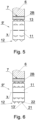
Fig. 5 shows a second embodiment of the perforating device 9', wherein triangular-shapedknives 13 are used for perforation. The shape of the knife is an isosceles triangle or a non-isosceles triangle. Initially, theknives 13 rotate with theroller 11 and perforate thewrapper material 2X, and then as theroller 11 continues to rotate, theknives 13 plunge into thesegment 2B and cut thewrapper material 2X. It is possible to use a singlewide knife 13 having a width of theroller 11 or several narrower knives. The forces created when the triangular-shaped knife plunges into the segment are directed in opposite directions, offsetting each other out and preventing the segment from moving when the wrapper is cut. Perforating devices equipped with knives with different angles of inclination can be used, depending on the strength of the wrapper material. -
Fig. 6 shows an embodiment of a perforating device 9' using knives 13' withblades 21 and curved cutting edges 22. Theblades 21 produce maximum unit pressure on thewrapper material 2X, facilitating perforation, after which thewrapper material 2X is cut by the cutting edges 22. This shape of the knives 13' is suitable for a strong,hard wrapper material 2X. The perforatingdevice wrapper material 2X to weaken thewrapper material 2X sectionally, making it easier to completely tear thewrapper material 2X and extract the filler material in the next step of the recovery process. - In the embodiment shown in
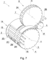
Fig. 7 , a separating device 1' is presented wherein the rod-like articles 2 are conveyed on afirst conveyor 4 in the form of a drum withfirst grooves 5. The separating device 1' is provided with apositioning unit 14 for adjusting the position of the multi-segment rod-like article 2 in thefirst groove 5 in a direction transverse to the direction of movement of the first conveyinggroove 5, i.e. axially along the axis ofgroove 5 so that only thesegments 2B are pressed by thesecond grooves 7 of thesecond conveyor 6. By positioning the multi-segment rod-like article 2, the risk of unwanted pressing of segments adjacent tosegment 2B is reduced, which in turn increases the effectiveness of tearing thewrapper 2X at the boundary between the adjacent segments and the tear line is approximate in shape to a circle. Thepositioning unit 14 comprises astop bar 15 andnozzles 16 that supply compressed air to press thearticles 2 against thestop bar 15. The separatedsegment 2B is conveyed to the perforating device 9' and held in thesecond groove 7 by means of a vacuum supplied throughholes 24 in thesecond groove 7. The rotation axis k of the perforating device 9', the rotation axis m of thesecond conveyor 6 and the rotation axis n of thefirst conveyor 5 are parallel to each other. Additionally, arow 12 ofknives 13 in the perforating device 9' is located parallel to the rotation axis k. Thesegment 2B is cylindrical, and theknives 13 perforate along the generatix of this cylinder, with the perforation being performed on the side opposite the holding area of thesegment 2B by means of a vacuum. - The
separating device 1 comprises afeeder 17 for placing the multi-segment rod-like article 2 on thefirst conveyor 4 as shown inFig. 1 . The multi-segment rod-like article 2 can be fed transversely to the axis of thearticle 2 as well as in line with the axis of thearticle 2. Theseparating device 1 is provided with acontainer 18 for the separatedsegments 2B andcontainers segments
Claims (10)
- A separating device (1) for separating a multi-segment rod-like article (2) of tobacco industry comprising segments (2A, 2B, 2C, 2D) wrapped with a wrapper material (2X), the device comprising:- a first conveyor (4) for conveying multi-segment rod-like articles (2) and having first grooves (5);- a second conveyor (6) for conveying separated segments (2B) after separation of the multi-segment rod-like article (2), having second grooves (7);- wherein the first conveyor (4) and the second conveyor (6) are positioned so that a first movement track (5T) of the first groove (5) and a second movement track (7T) of the second groove (7) intersect;- wherein the first conveyor (4) and the second conveyor (6) are synchronized such that in an intersection zone (X) of said movement tracks (5T, 7T), the first groove (5) is positioned opposite the second groove (7) so that the first groove (5) and the second groove (7) push adjacent segments (2A, 2B, 2C) in opposite directions (PA, PB, PC);characterized in that- the device (1) further comprises a perforating device (9) for perforating and/or incising the wrapper material (2X) of the separated segment (2B).
- The device according to claim 1, wherein the perforating device (9) is configured to perforate and/or incise the wrapper material (2X) of the separated segment (2B) transported in the second groove (7) on the second conveyor (6).
- The device according to claim 1 or 2, wherein the perforating device (9) has a form of a rotating roller (11) with needles (10).
- The device according to claim 1 or 2, wherein the perforating device (9) has a form of a rotating roller (11) with knives (13, 13').
- The device according to claim 4, wherein the rotation axis (k) of the roller (11) is located parallel to the rotation axis (m) of the perforating device (9).
- The device according to any one of claims 1 to 5, wherein the first conveyor (4) has a form of a chain conveyor.
- The device according to any one of claims 1 to 5, wherein the first conveyor (4) has a form of a rotary drum conveyor.
- The device according to any one of claims 1 to 7, further comprising a positioning unit (14) for correcting the position of the multi-segment rod-like article (2) in the first groove (5) in a direction transverse to the direction of movement of the first groove (5).
- The device according to any one of claims 1 to 8, further comprising a feeder (17) for placing the multi-segment rod-like article (2) on the first conveyor (4).
- A method for separating a multi-segment rod-like article (2) of tobacco industry comprising segments (2A, 2B, 2C, 2D) wrapped with a wrapper (2X), the method comprising the steps of:- transferring the multi-segment rod-like article (2) in a first groove (5) of a first conveyor (4) along a first movement track (5T),- rotating a second conveyor (6) so that a second groove (7) of the second conveyor (6) moves along a second movement track (7T) such that the first movement track (5T) of the first groove (5) and the multi-segment rod-like article (2) and the second movement track (7T) of the second groove (7) intersect,- pressing adjacent segments (2A, 2B, 2C) in opposite directions (PA, PB, PC) in the intersection zone (X) of said movement tracks (5T, 7T),- moving a separated segment (2B) of the multi-segment rod-like article (2) in the second groove (7) of the second conveyor (6) to a perforating device (9),characterized by:- perforating and/or incising the wrapper material (2X) of the separated segment (2B) moved in the second groove (7) of the second conveyor (6) with the perforating device (9).
Priority Applications (1)
| Application Number | Priority Date | Filing Date | Title |
|---|---|---|---|
| EP23215589.5A EP4570083B1 (en) | 2023-12-11 | 2023-12-11 | A device for separating a multi-segment rod-like article of tobacco industry |
Applications Claiming Priority (1)
| Application Number | Priority Date | Filing Date | Title |
|---|---|---|---|
| EP23215589.5A EP4570083B1 (en) | 2023-12-11 | 2023-12-11 | A device for separating a multi-segment rod-like article of tobacco industry |
Publications (2)
| Publication Number | Publication Date |
|---|---|
| EP4570083A1 true EP4570083A1 (en) | 2025-06-18 |
| EP4570083B1 EP4570083B1 (en) | 2026-04-22 |
Family
ID=89168222
Family Applications (1)
| Application Number | Title | Priority Date | Filing Date |
|---|---|---|---|
| EP23215589.5A Active EP4570083B1 (en) | 2023-12-11 | 2023-12-11 | A device for separating a multi-segment rod-like article of tobacco industry |
Country Status (1)
| Country | Link |
|---|---|
| EP (1) | EP4570083B1 (en) |
Citations (5)
| Publication number | Priority date | Publication date | Assignee | Title |
|---|---|---|---|---|
| US2815029A (en) * | 1954-04-14 | 1957-12-03 | Zigarettenfabrik Haus Neuerbur | Method and means for tearing out filters from defective filter cigarettes |
| DE1204118B (en) | 1962-11-20 | 1965-10-28 | Hauni Werke Koerber & Co Kg | Method and device for cutting cigarettes and other stick-shaped objects |
| PL204696A1 (en) | 1978-02-16 | 1979-09-24 | Wytwornia Sprzetu Komunikacyjn | DISPENSER ESPECIALLY FOR AIR SPREADING OF CHEMICALS AND LOOSE MATERIALS |
| EP2364605A2 (en) | 2010-03-11 | 2011-09-14 | International Tobacco Machinery Poland Sp. z o.o. | Method of opening cigarette covers and an assembly for opening cigarette covers in a machine for recovering tobacco from defective and/or substandard cigarettes |
| EP2545790A1 (en) * | 2011-07-12 | 2013-01-16 | Köhl Maschinenbau AG | Cigarette disassembly device for filter cigarettes and cigarette disassembly machine and method for disassembling a filter cigarette |
-
2023
- 2023-12-11 EP EP23215589.5A patent/EP4570083B1/en active Active
Patent Citations (5)
| Publication number | Priority date | Publication date | Assignee | Title |
|---|---|---|---|---|
| US2815029A (en) * | 1954-04-14 | 1957-12-03 | Zigarettenfabrik Haus Neuerbur | Method and means for tearing out filters from defective filter cigarettes |
| DE1204118B (en) | 1962-11-20 | 1965-10-28 | Hauni Werke Koerber & Co Kg | Method and device for cutting cigarettes and other stick-shaped objects |
| PL204696A1 (en) | 1978-02-16 | 1979-09-24 | Wytwornia Sprzetu Komunikacyjn | DISPENSER ESPECIALLY FOR AIR SPREADING OF CHEMICALS AND LOOSE MATERIALS |
| EP2364605A2 (en) | 2010-03-11 | 2011-09-14 | International Tobacco Machinery Poland Sp. z o.o. | Method of opening cigarette covers and an assembly for opening cigarette covers in a machine for recovering tobacco from defective and/or substandard cigarettes |
| EP2545790A1 (en) * | 2011-07-12 | 2013-01-16 | Köhl Maschinenbau AG | Cigarette disassembly device for filter cigarettes and cigarette disassembly machine and method for disassembling a filter cigarette |
Also Published As
| Publication number | Publication date |
|---|---|
| EP4570083B1 (en) | 2026-04-22 |
Similar Documents
| Publication | Publication Date | Title |
|---|---|---|
| KR101398745B1 (en) | Filter component cutting system | |
| EP2364605B1 (en) | Method and assembly for recovering tobacco from defective cigarettes | |
| JP5545959B2 (en) | Rotating disk knife, method of attaching rotating disk knife and method of removing rotating disk knife | |
| EP2773228B1 (en) | Smokeable material recovery | |
| GB2494159A (en) | Cigarette processing assembly for reclaiming tobacco | |
| CN106535670B (en) | Unit including tipping paper suction rollers | |
| US8721404B2 (en) | Device and method for completely removing at least one part of the breast cartilage from a poultry carcass that is free of breast meat | |
| US5001951A (en) | Apparatus for cutting apart cigarette packs in preparation for recovery of the tobacco in the cigarettes | |
| EP3214958B1 (en) | Smoking article assembly machine and method of making a smoking article | |
| EP3197302B1 (en) | Machine for making smokers' articles | |
| EP4570083B1 (en) | A device for separating a multi-segment rod-like article of tobacco industry | |
| EP3114945B1 (en) | Disassembly device and disassembly method for smokers' articles | |
| US4747591A (en) | Apparatus for separating folded perforated reel papers | |
| US6769435B2 (en) | Cigarette maker outfeed unit | |
| PL216538B1 (en) | Perforating unit for rodlike elements, especially cigarettes | |
| EP3592159B1 (en) | Unit and method for separating plugwraps and applying them to rod-shaped smoking articles | |
| PL230026B1 (en) | Device for slitting cigarettes and method for slitting cigarettes | |
| WO1992021566A1 (en) | Bread unwrapping apparatus | |
| JPH05337892A (en) | Rotary cross-cutter for final treatment of web | |
| WO2015189781A1 (en) | Method and apparatus for removing tobacco from cigarettes | |
| US5722318A (en) | Olive stoning machines | |
| HK1239469B (en) | Smoking article assembly machine and method of making a smoking article | |
| PL204696B1 (en) | Apparatus for recovering tobacco from rod-like tobacco products |
Legal Events
| Date | Code | Title | Description |
|---|---|---|---|
| PUAI | Public reference made under article 153(3) epc to a published international application that has entered the european phase |
Free format text: ORIGINAL CODE: 0009012 |
|
| STAA | Information on the status of an ep patent application or granted ep patent |
Free format text: STATUS: THE APPLICATION HAS BEEN PUBLISHED |
|
| AK | Designated contracting states |
Kind code of ref document: A1 Designated state(s): AL AT BE BG CH CY CZ DE DK EE ES FI FR GB GR HR HU IE IS IT LI LT LU LV MC ME MK MT NL NO PL PT RO RS SE SI SK SM TR |
|
| STAA | Information on the status of an ep patent application or granted ep patent |
Free format text: STATUS: REQUEST FOR EXAMINATION WAS MADE |
|
| 17P | Request for examination filed |
Effective date: 20251210 |
|
| RIC1 | Information provided on ipc code assigned before grant |
Ipc: A24C 5/36 20060101AFI20251216BHEP |
|
| GRAP | Despatch of communication of intention to grant a patent |
Free format text: ORIGINAL CODE: EPIDOSNIGR1 |
|
| STAA | Information on the status of an ep patent application or granted ep patent |
Free format text: STATUS: GRANT OF PATENT IS INTENDED |
|
| INTG | Intention to grant announced |
Effective date: 20260204 |
|
| GRAS | Grant fee paid |
Free format text: ORIGINAL CODE: EPIDOSNIGR3 |
|
| GRAA | (expected) grant |
Free format text: ORIGINAL CODE: 0009210 |
|
| STAA | Information on the status of an ep patent application or granted ep patent |
Free format text: STATUS: THE PATENT HAS BEEN GRANTED |
|
| P01 | Opt-out of the competence of the unified patent court (upc) registered |
Free format text: CASE NUMBER: UPC_APP_0008991_4570083/2026 Effective date: 20260306 |
|
| AK | Designated contracting states |
Kind code of ref document: B1 Designated state(s): AL AT BE BG CH CY CZ DE DK EE ES FI FR GB GR HR HU IE IS IT LI LT LU LV MC ME MK MT NL NO PL PT RO RS SE SI SK SM TR |
|
| REG | Reference to a national code |
Ref country code: CH Ref legal event code: F10 Free format text: ST27 STATUS EVENT CODE: U-0-0-F10-F00 (AS PROVIDED BY THE NATIONAL OFFICE) Effective date: 20260422 Ref country code: GB Ref legal event code: FG4D |
|
| REG | Reference to a national code |
Ref country code: DE Ref legal event code: R096 Ref document number: 602023015674 Country of ref document: DE |