EP4570067A2 - A rodent trap - Google Patents
A rodent trap Download PDFInfo
- Publication number
- EP4570067A2 EP4570067A2 EP25165657.5A EP25165657A EP4570067A2 EP 4570067 A2 EP4570067 A2 EP 4570067A2 EP 25165657 A EP25165657 A EP 25165657A EP 4570067 A2 EP4570067 A2 EP 4570067A2
- Authority
- EP
- European Patent Office
- Prior art keywords
- trigger member
- rodent trap
- rodent
- base
- state
- Prior art date
- Legal status (The legal status is an assumption and is not a legal conclusion. Google has not performed a legal analysis and makes no representation as to the accuracy of the status listed.)
- Pending
Links
Images




Classifications
-
- A—HUMAN NECESSITIES
- A01—AGRICULTURE; FORESTRY; ANIMAL HUSBANDRY; HUNTING; TRAPPING; FISHING
- A01M—CATCHING, TRAPPING OR SCARING OF ANIMALS; APPARATUS FOR THE DESTRUCTION OF NOXIOUS ANIMALS OR NOXIOUS PLANTS
- A01M23/00—Traps for animals
- A01M23/24—Spring traps, e.g. jaw or like spring traps
- A01M23/30—Break-back traps, i.e. mouse-trap type
-
- A—HUMAN NECESSITIES
- A01—AGRICULTURE; FORESTRY; ANIMAL HUSBANDRY; HUNTING; TRAPPING; FISHING
- A01M—CATCHING, TRAPPING OR SCARING OF ANIMALS; APPARATUS FOR THE DESTRUCTION OF NOXIOUS ANIMALS OR NOXIOUS PLANTS
- A01M23/00—Traps for animals
- A01M23/24—Spring traps, e.g. jaw or like spring traps
-
- A—HUMAN NECESSITIES
- A01—AGRICULTURE; FORESTRY; ANIMAL HUSBANDRY; HUNTING; TRAPPING; FISHING
- A01M—CATCHING, TRAPPING OR SCARING OF ANIMALS; APPARATUS FOR THE DESTRUCTION OF NOXIOUS ANIMALS OR NOXIOUS PLANTS
- A01M23/00—Traps for animals
- A01M23/24—Spring traps, e.g. jaw or like spring traps
- A01M23/245—Auxiliary devices for spring traps, e.g. attaching systems
-
- G—PHYSICS
- G01—MEASURING; TESTING
- G01D—MEASURING NOT SPECIALLY ADAPTED FOR A SPECIFIC VARIABLE; ARRANGEMENTS FOR MEASURING TWO OR MORE VARIABLES NOT COVERED IN A SINGLE OTHER SUBCLASS; TARIFF METERING APPARATUS; MEASURING OR TESTING NOT OTHERWISE PROVIDED FOR
- G01D5/00—Mechanical means for transferring the output of a sensing member; Means for converting the output of a sensing member to another variable where the form or nature of the sensing member does not constrain the means for converting; Transducers not specially adapted for a specific variable
- G01D5/12—Mechanical means for transferring the output of a sensing member; Means for converting the output of a sensing member to another variable where the form or nature of the sensing member does not constrain the means for converting; Transducers not specially adapted for a specific variable using electric or magnetic means
- G01D5/14—Mechanical means for transferring the output of a sensing member; Means for converting the output of a sensing member to another variable where the form or nature of the sensing member does not constrain the means for converting; Transducers not specially adapted for a specific variable using electric or magnetic means influencing the magnitude of a current or voltage
- G01D5/142—Mechanical means for transferring the output of a sensing member; Means for converting the output of a sensing member to another variable where the form or nature of the sensing member does not constrain the means for converting; Transducers not specially adapted for a specific variable using electric or magnetic means influencing the magnitude of a current or voltage using Hall-effect devices
Definitions
- the present invention relates to a rodent trap. More specifically the present invention relates to a rodent trap of a snap type comprising a sensor to detect states of the trap.
- the snap trap is designed to trap and kill a rodent between a spring loaded bar, here referred to as a kill bar, and a base of the trap.
- traps are made for mice or rats.
- the main difference between a trap made for rats and a trap made for mice is that rat traps are larger and made such that the bar hits the rat with a greater force than the mouse in the mouse trap.
- a problem with these traps is that they might fail in trapping or killing a rodent which has triggered the trap.
- a rodent may be fast enough to escape the trap before being trapped by the kill bar.
- a rodent may also be so large that even if it is hit by the kill bar it is not killed or not even trapped by the rodent trap.
- One objective is to provide a rodent trap which is robust and reliable in determining an armed ready state, a sprung empty state and if a rodent has been caught in a caught state thereof.
- a rodent trap comprising a base, a kill bar, wherein the kill bar is pivotably connected to the base, a trigger member, wherein the trigger member is pivotably connected to the base and arranged between the base and the kill bar such that when the trigger member is activated the kill bar is released and traps or kills a rodent, the rodent trap comprises a sensor configured to detect at least three different distances (A 1 , A 2 , A 3 ) between the trigger member and the base.
- a method for determining a ready state, a sprung empty state and a caught state of a rodent trap comprising a base, a kill bar and a trigger member arranged between the base and the kill bar such that when the trigger member is activated the kill bar is released and traps or kills the rodent, the method comprising detecting at least three different distances (A 1 , A 2 , A 3 ) between the trigger member and the base.
- a rodent trap system comprising a plurality of rodent traps, the rodent trap comprising a base, and a kill bar, wherein the kill bar is pivotably connected to the base, a trigger member, wherein the trigger member is pivotably connected to the base and arranged between the base and the kill bar such that when the trigger member is activated the kill bar is released and traps a rodent, a sensor configured to detect at least three different distances (A 1 , A 2 , A 3 ) between the trigger member and the base, a wireless transmitter in communication with the sensor and being configured to transmit any of the at least three different distances to at least one receiver, and/or transmit any of a ready state, a sprung empty state and a caught state of the rodent trap associated with the at least three different distances to at least one receiver, the rodent trap system comprising said at least one receiver.
- Having a sensor configured to detect at least three different distances between the trigger member and the base provides for a robust and reliable detection of different states of the rodent trap, since the position of the trigger member can be accurately determined, where said position is indicative of whether a rodent has been caught or not after the trap has been triggered.
- Some examples of the disclosure provide for a more robust and reliable detection of a ready state, a sprung empty state and a caught state of a rodent trap.
- Some examples of the disclosure provide for a facilitated and more efficient managing of a plurality of rodent traps in a rodent trap system.
- Fig. 1 is a schematic perspective view of an example of a rodent trap 1 comprising a base 10 and a kill bar 11.
- the kill bar 11 is pivotably connected to the base 10 by a connection bar 20 extending across the base 10 essentially in parallel with the kill bar 11.
- the kill bar 11 is also connected to a spring (not shown), for spring loading of the kill bar.
- Fig. 1 shows an armed ready state of the rodent trap 1 where the rodent trap 1 has been set by forcing the kill bar 11 against the spring and locked in place by a locking mechanism 21.
- the example in Fig. 1 shows the locking mechanism 21 engaging with an angled extension bar 11' of the kill bar 11, where the angled extension bar 11' locks into a notch 21' of the locking mechanism 21. It should be understood however that the kill bar 11 may be locked into place in an armed ready state of the rodent trap 1 by various locking mechanisms.
- the rodent trap 1 comprises a trigger member 12.
- the kill bar 11 is releasable from the locking mechanism 21 by the trigger member 12.
- the trigger member 12 is engaged with the locking mechanism 21 so that pivoting of the trigger member 12 unlocks the locking mechanism 21 from an armed position when holding the kill bar 11 in the ready state.
- the trigger member 12 is pivotably connected to the base 10 and arranged between the base 10 and the kill bar 11 such that when the trigger member 12 is activated by the rodent, the locking mechanism 21 is released which thereby releases the kill bar 11 which in turn traps or kills the rodent.
- the kill bar 11 may e.g. be released by releasing the angled extension bar 11' from notch 21'.
- the effect of the rodent triggering the trigger member 12 is that the kill bar 11 quickly and forcibly moves towards the base 10 and thus hits and traps the rodent against the base 10.
- the kill bar 11 will hit the rodent with a force which is enough to produce an impulse which kills the rodent instantaneously.
- a bait is usually placed on or in a bait holder 23 which may be arranged on or near the trigger member 12 in order to attract a rodent towards the trigger member 12.
- a rodent comes into contact with the trigger member 12 it should pivot the trigger member 12 which unlocks the locking mechanism 21 and thus releases the kill bar 11 as explained above.
- the rodent trap 1 comprises a sensor 13, 14, which is configured to detect at least three different distances (A 1 , A 2 , A 3 ) between the trigger member 12 and the base 10.
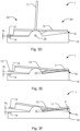
- Figs. 3A-G show examples of such detected distances (A 1 , A 2 , A 3 ) between the trigger member 12 and the base 10.
- the sensor 13, 14, is thus arranged to sense the position of the trigger member 12 relative to the base 10 as the trigger member 12 pivots with respect to the base 10 during the operational states of the rodent trap 1, as exemplified in Figs. 3A-G .
- Fig. 1 and Figs. 3A-G show examples where the sensor 13, 14, is arranged at an end of the rodent trap 1, essentially opposite the end where the rodent is trapped by the kill bar 11.
- the senor 13, 14 may be arranged at other positions, along the extension of the base 10 and trigger member 12 to detect at least three different distances (A 1 , A 2 , A 3 ) between the trigger member 12 and the base 10 while providing for the advantageous benefits as further described below.
- Increasing the distance between the sensor 13, 14, and a pivot point of the trigger member 12, which may be the arranged at or adjacent the connection bar 20 in some examples, provides for increasing the length of the range of motion of the trigger member 12 relative to the base 10. This may provide for a facilitated distinguishing and detecting of the at least three different distances (A 1 , A 2 , A 3 ), and thus for a more accurate detection of the states of the rodent trap 1.
- the sensor 13, 14, may comprise a sensor suitable to detect the distance (A 1 , A 2 , A 3 ) between the trigger member 12 and the base 10, e.g. one or more of an electrical sensor, mechanical sensor, electro-mechanical sensor, optical sensor, or a magnetic sensor.
- the sensor 13, 14, may comprise one or more sensor components 13, 14, arranged on the base 10 and/or on the trigger member 12.
- Fig. 1 and Figs. 3A-G show examples where the sensor 13, 14, comprises two sensor components 13, 14, arranged on the trigger member 12 and the base 10, respectively.
- a first sensor component 13, arranged on the trigger member 12 may be arranged essentially opposite a second sensor component 14 arranged on the base 10.
- the first and second sensor components 13, 14, may be in communication to detect a variation in the separation between the first and second sensor components 13, 14, as the trigger member 12 pivots relative to the base 10. At least three different distances (A 1 , A 2 , A 3 ) between the trigger member 12 and the base 10 may thus be determined as the amount of said separation varies.
- the first or second sensor component 13, 14, is a passive component which do not need a power supply, such as a magnet.
- the first or second sensor component 13, 14, is a part of the structure forming the trigger member 12 or the base 10 which is chosen as a passive detection point for e.g.
- a proximity sensor such as an optical sensor, configured to detect the at least three different distances (A 1 , A 2 , A 3 ) between the trigger member 12 and the base 10.
- the passive detection point be in such case be a flat surface in the material from which the trigger member 12 or base 10 is formed.
- the first sensor component 13 and the second sensor component 14 may comprise such passive detection point and proximity sensor, respectively, in one example.
- the senor 13, 14, comprises a magnetic sensor 13, 14.
- the magnetic sensor 13, 14, may comprise a magnet 13 as a first sensor component 13 and a magnetic sensor unit 14 as a second sensor component 14, as described further below.
- Having a sensor 13, 14, detecting at least three different distances (A 1 , A 2 , A 3 ) between the trigger member 12 and the base 10 provides for a robust and reliable detection of different states of the rodent trap, since the position of the trigger member 12 can be accurately determined, where said position is indicative of whether a rodent has been caught or not after the trap has been triggered.
- Having the sensor 13, 14, detecting the position of the trigger member 12 alleviates the need for having detection capability directly on the position of the kill bar 11 in sensor-based rodent traps. This allows for optimizing the function of the kill bar 11 separately, e.g. with respect to speed, force, or re-useability, without having concern of providing detection functionality.
- a more efficient rodent trap 1 is thus provided with a more reliable detection of the different states of the rodent trap.
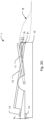
- Figs. 3D-G shows an armed ready state of the rodent trap 1, i.e. the kill bar 11 has been forced to its armed position and locked by the locking mechanism 21 ( Fig. 1 ), where the sensor 13, 14, is arranged to detect a distance denoted A 1 between the trigger member 12 and the base 10.
- the trigger member 12 assumes a first position (p 1 ) in this state, as further denoted in Fig. 3D .
- Fig. 3A shows an alternative side-view of this state of the rodent trap 1.
- Fig. 3E shows a state of the rodent trap 1 where the kill bar 11 is in an unloaded position and in abutment with the base 10. This state corresponds to a sprung empty state of the rodent trap 1, i.e. the trigger member 12 has been triggered, moving the kill bar 11 forcibly down towards the base 10, but no rodent is trapped by the kill bar 11.
- the kill bar 11 cause movement of the trigger member 12 from the first position (p 1 ) to a second position (p 2 ) when the kill bar 11 moves from the armed position ( Fig. 3D ) to the unloaded position in Fig. 3E .
- the sensor 13, 14 is arranged to detect a distance denoted A 3 between the trigger member 12 and the base 10, which accordingly is different from the distance denoted A 1 in Fig. 3D .
- Fig. 3C shows an alternative side-view of this state of the rodent trap 1.
- the trigger member 12 is movable relative the kill bar 11 in a direction towards the base 10 from the second position (p 2 ) to a third position (p 3 ) while the kill bar 11 is in said unloaded position, as schematically illustrated in Fig. 3F .
- a gap (d) can be arranged in between the second (p 2 ) and third positions (p 3 ) of the trigger member 12 which accommodates at least part of the rodent (R) when trapped in the rodent trap 1, as further schematically illustrated in Fig. 3G .
- the position of the trigger member 12 in the second position (p 2 ) is schematically illustrated in Fig. 3G with dashed lines for comparison.This is referred to as the caught state of the rodent trap 1.
- the sensor 13, 14 is arranged to detect a distance denoted A 2 between the trigger member 12 and the base 10, which is different from the distance denoted A 3 in Fig. 3E since the trigger member 12 has moved to the third position (p 3 ), e.g. by a rodent (R) pushing down on the trigger member 12 as exemplified in Fig. 3G .
- Fig. 3B shows an alternative side-view of this state of the rodent trap 1. It should be understood that while the trigger member 12 is movable relative the kill bar 11 from the second position (p 2 ) to the third position (p 3 ) while the kill bar 11 is in said unloaded position, as described with reference to Fig.
- the trapping of a rodent (R) under the kill bar 11, as shown in Fig. 3G can alter the position of the kill bar 11 depending on how large part of the rodent is trapped.
- having a trigger member 12 which is movable from the second position (p 2 ) to the third position (p 3 ) as described above provides for the detection of the third distance A 3 when a rodent has been trapped, independent on the current position of the kill bar 11 (in Fig. 3G ).
- the trigger member 12 may be resiliently movable from the second position (p 2 ) to the third position (p 3 ) upon application of a force (F) on the trigger member 12 towards the base 10, as illustrated in Fig. 3F .
- the trigger member 12 may be biased to move from the third position (p 3 ) to the second position (p 2 ) when the force (F) is removed.
- The provides for having the trigger member 12 returning to the second position (p 2 ) if a rodent first depresses the trigger member 12 to the third position (p 3 ) but later manages to escape from underneath the kill bar 11.
- the sensor 13, 14, detects the second distance A 2 (different from A 1 and A 3 ) which is indicative of the sprung empty state of the rodent trap 1, and may additionally provide the information that a rodent was first trapped but then escaped.
- the sensor 13, 14, may thus be configured to relate a first trigger distance (A 1 ) of the at least three different distances (A 1 , A 2 , A 3 ) to the first position (p 1 ) and the ready state of the rodent trap 1.
- the sensor 13, 14, may be configured to relate a second trigger distance (A 2 ) of the at least three different distances (A 1 , A 2 , A 3 ) to said third position (p 3 ) and the caught state of the rodent trap 1.
- the sensor 13, 14, may be configured to relate a third trigger distance (A 3 ) of the at least three different distances (A 1 , A 2 , A 3 ) to the second position (p 2 ) and the sprung empty state of the rodent trap 1.
- Fig. 2 is a top view of an example of the rodent trap 1. From this view it can be seen that the kill bar 11 may be formed in such a way that the kill bar 11 extends outside of the trigger member 12 on a left side 30a and right side 30b of the trigger member 12. I.e. the inner separation between arms 11a, 11b, which connect to the horizontal kill bar 11 is wider than the width (w) of the trigger member 12. The kill bar 11, or the arms 11a, 11b, thereof may thus strike against edges 25a, 25c, of the base 10 on a left and right side of the trigger member 12, without having the arms 11a, 11b, interfering with the trigger member 12.
- Edges 25a, 25c may in some examples comprise teeth and/or grooves, also denoted 25a and 25c in Fig. 2 .
- the kill bar arms 11a, 11b may extend to, and conform with, the arrangement of the aforementioned edges 25a, 25c, in the examples of Figs. 1 - 3 when activated and forced down by a kill bar spring (not shown).
- the edges 25a, 25c will therefore limit the downward movement of the kill bar 11 toward the base 10.
- the kill bar 11, and/or arms 11a, 11b, thereof rest on edges 25a, 25c, a top of the kill bar 11 (denoted with reference numeral 11 in Fig.
- the trigger member 12 may be biased to move towards the first position (p 1 ) in some examples. This provides for facilitating the arming of the rodent trap 1 in the ready position ( Fig. 3D ). In case the trigger member 12 has such bias, the kill bar 11 keeps the trigger member 12 from moving towards the first position (p 1 ) when pushing down on the trigger member 12 ( Fig. 3E ).
- the bias of the trigger member 12 may be provided by a trigger spring (not shown), which urges the trigger member 12 upward back to the first position (p 1 ).
- the trigger member 12 may not be connected to the trigger spring but instead the trigger member 12 strives towards the first position (p 1 ) due to the trigger member 12 having a larger mass on a locking mechanism side 33 of the connection rod 20 than towards a side 34 of the trigger member 12 where the rodent triggers the trigger member 12 (see references in Fig. 3D ).
- the locking mechanism side 33 of the trigger member 12 may act as a counterweight to the opposite side 34 of the trigger member 12. So, the locking mechanism side 33 is heavier, and this will make the trigger member 12 return to the first position (p 1 ) ( Fig. 3D ) unless the kill bar 11 is pushing the trigger member 12 down ( Fig. 3E ).
- a top of the kill bar 11 may in some examples extend above the trigger member 12 along edge 25b.
- the kill bar 11 or the trigger member 12 may in those examples comprise a linkage member that mechanically connects the kill bar 11 and the trigger member 12 so that the trigger member 12 is kept in a position corresponding to the second position (p 2 ).
- the trigger member 12 is configured to move from the second position (p 2 ) to the third position (p 3 ), to accommodate a rodent, as described above with reference to Figs. 3F-G , independent on how the pivot angle of the trigger member 12 is restricted to the second position (p 2 ) at the sprung empty state of the rodent trap 1.
- edges 25a-c of the base 10 comprises a sharp elevation from the base 10.
- the edges 25a-c comprises teeth and/or grooves.
- the rodent trap 1 may only have teeth/grooves and/or sharp elevations along one edge 25a-c. Teeth/grooves and/or sharp elevations may be mixed or combined along different edges 25a-c. In one example the edges 25a-c do not comprise teeth/grooves, or sharp elevations, but only blunt edges.
- the sensor 13, 14, may comprise a magnetic sensor 13, 14, as mentioned above.
- the trigger member 12 comprises a magnet 13 and the base 10 comprises a magnetic sensor unit 14.
- the magnetic sensor unit 14 is configured to detect the magnetic field from the magnet 13. The magnetic field varies depending on the amount of separation between the magnet 13 and the magnetic sensor unit 14.
- the magnet 13 and the magnetic sensor unit 14 may be arranged essentially opposite eachother on the trigger member 12 and the base 10, respectively.
- the magnetic sensor 13, 14, may thus relate the variation in magnetic field to the aforementioned at least three different distances (A 1 , A 2 , A 3 ) between the trigger member 12 and the base 10.
- the magnetic sensor 13, 14, comprises a Hall effect sensor or a reed switch which is configured to detect and convert a magnetic field into a current and/or voltage difference which can be related to the different distances (A 1 , A 2 , A 3 ).
- Other types of magnetic sensors 13, 14, may also be used to detect the magnetic field and relate the magnetic field to the distances (A 1 , A 2 , A 3 ). It is conceivable that in one example the magnet 13 is arranged on the base 10 and the magnetic sensor unit 14 is arranged on the trigger member 12.
- a magnetic sensor 13, 14, as described allows for accurately determine if the rodent trap 1 is in the ready state to catch a rodent, if the trap is in a sprung empty state, i.e. in false-positive state, or in the caught state when the rodent has been caught.
- a magnetic sensor 13, 14, provides for reduced complexity and a robust rodent trap 1 with minimal maintenance.
- the sensor 13, 14, may however comprise any sensor suitable to detect the distance (A 1 , A 2 , A 3 ) between the trigger member 12 and the base 10, e.g. one or more of an electrical sensor, mechanical sensor, electro-mechanical sensor, or an optical sensor.
- the trigger member 12 comprises an extension 15.
- the extension 15 may comprise the magnet 13, as schematically illustrated in e.g. Fig. 2 and Fig. 3E .
- the distance between the three different trigger distances (A 1 , A 2 , A 3 ) is increased and thus also aids in facilitating distinguishing and detecting the three different distances (A 1 , A 2 , A 3 ) by the magnetic sensor 13, 14.
- the detection of the different distances is further exemplified with reference to Figs. 3A-C .
- the sensor 13, 14, comprises a magnetic sensor 13, 14, in the described example.
- Fig. 3A is a side view of an example of the rodent trap 1 when there is a relatively small distance A 1 between the magnet 13 and the magnetic sensor unit 14, i.e. the trap is in the ready state.
- the trigger member 12 and the magnet 13 may be arranged in a parallel or almost parallel position relative to the base 10.
- the magnet 13 is arranged in close proximity to the magnetic sensor unit 14 and the first distance A 1 is thus very small, or the magnet 13 can even abut the base 10.
- the magnetic sensor unit 14 is configured to relate this first distance A 1 to the ready state of the rodent trap 1.
- the ready state means that the kill bar 11 is locked in place by the locking mechanism 21 and thus can be activated when the rodent activates the trigger member 12.
- FIG. 3B Illustrated in Fig. 3B is a side view of an example of the rodent trap 1 when there is a relatively large distance A 2 between the magnet 13 and the magnetic sensor unit 14.
- the rodent trap 1 is here in the caught state, corresponding to the description with respect to Figs. 3F-G above.
- the trigger member 12 and the magnet 13 may here be arranged in a maximum or close to maximum tilted position relative to the base 10.
- the magnet 13 may thus be arranged at the largest distance A 2 away from the magnetic sensor unit 14.
- the magnetic sensor unit 14 is configured to relate this second distance A 2 to the caught state of the rodent trap 1. Hence, the rodent trap 1 has caught the rodent in the rodent trap 1.
- the trigger member 12 may pivot around the connection bar 20. In other examples, the trigger member 12 may pivot around other parts of the rodent trap 1. Thus, at the end of the rodent trap 1 with edges 25a-25c, an end of the trigger member 12 may be fully depressed to abut the base 10, when in the maximum or close to maximum tilted state. At the opposite end of the trigger member 12, the magnet 13 together with the base 10, and/or locking mechanism 21 may stop the trigger member 12 from tilting in an opposite direction, so that the trigger member 12 may assume a parallel position with respect to the base 10, i.e. in the ready state.
- the trigger member 12 may be kept in a somewhat tilted position by the kill bar 11, as illustrated in e.g. Fig. 3E .
- the trigger member 12 In order to get the trigger member 12 to fully tilt, and in some examples touch the base 10, and thus having the magnet 13 and magnetic sensor unit 14 at the largest or maximum distance A 2 something need to be placed in between the kill bar 11 and the trigger member 12.
- the largest distance A 2 is only realized when the rodent is actually caught and placed between the kill bar 11 and the trigger member 12, as exemplified in Fig. 3G .
- Fig. 3C Illustrated in Fig. 3C is a side view of an example of the rodent trap 1 when there is a medium distance A 3 between the magnet 13 and the magnetic sensor unit 14, the rodent trap 1 is in the false-positive or sprung empty state.
- the trigger member 12 and the magnet 13 is arranged in a slightly tilted position relative to the base 10 and the magnet 13 is arranged at the distance A 3 , which is between the first A 1 and second distance A 2 , to the magnetic sensor 14. This is the same position of the trigger member 12 as discussed above in relation to Fig. 2 , i.e. when the kill bar 11 pushes on the trigger member 12.
- the magnetic sensor unit 14 is configured to relate this third distance A 3 to the false-positive or sprung empty state of the rodent trap 1.
- the trigger member 12 In the false-positive state the rodent or something have triggered the trigger member 12 to unlock the locking mechanism 21 and thus sending the kill bar 11 downward to the edges 25a and 25c.
- the trigger member 12 due to the configuration of the kill bar 11, edges 25a and 25c and the trigger member 12, as discussed above in relation to Fig. 2 and Figs. 3F-G , the trigger member 12 will not be tilted in the maximum tilted position.
- the trigger member 12 will thus be placed in the slightly tilted position, as seen in Fig. 3C , or the position p 2 in Fig. 3E , different from the maximum tilted position, as seen in Fig. 3B , or the position p 3 in Fig. 3G .
- the magnet 13 and/or magnetic sensor unit 14 is arranged on or attached to the trigger member 12, or any extension 15 of the trigger member 12.
- the attachment can be performed by e.g. gluing the magnet 13 to the trigger member 12.
- connection rods 20 making up the connection bar 20, one on each end of the kill bar 11.
- the kill bars 11 may be placed next to each other and sometimes joined together by a weld.
- the kill bar 11 and the connection rods 20 are made from one continuous piece which is bent into the shape of the kill bar 11 and connection rod(s) 20.
- the rodent trap 1 comprises a wireless transmitter 50, exemplified by an antenna denoted with reference numeral 50.
- the rodent trap 1 may also comprise a wireless receiver, exemplified by an antenna denoted with reference numeral 50' in Fig. 4 .
- the wireless transmitter 50 is in communication with the sensor 13, 14.
- the communication may be electrical and/or wireless.
- the wireless transmitter and/or receiver 50, 50' may be any of a cellular unit such as GSM (Global System for Mobile Communications) unit, 3G, 4G or 5G unit, a wireless network unit, a Bluetooth unit or the like.
- the rodent trap 1 comprises a sim card holder for communication with the cellular unit.
- the wireless transmitter and/or receiver 50, 50' may be embedded in the base 10 and may communicate with external antennas 50, 50'. In some examples the transmitter and/or receiver 50, 50', may be embedded with the antennas 50, 50'. In some examples one antenna 50 may be utilized for the wireless communication. Alternatively, a plurality of antennas 50, 50', may be utilized, depending on reception needs.
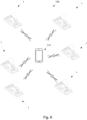
- the wireless transmitter 50 may be configured to transmit any of the at least three different distances (A 1 , A 2 , A 3 ) to a receiver 110, such as a remote receiver 110, as schematically illustrated in Fig. 6 .
- the wireless transmitter 50 is may be configured to transmit any of a ready state, a sprung empty state and a caught state of the rodent trap 1 associated with the at least three different distances (A 1 , A 2 , A 3 ), as described above, to a remote receiver 110.
- the wireless transmitter 50 allows for communicating the detected state, i.e. the armed ready state, the caught state, or the false-positive/sprung empty state, and/or the distances (A 1 , A 2 , A 3 ), to a receiver 110.
- the receiver 110 can e.g. be a mobile phone, a computer, lap-top, a tablet, a webserver or the like that is configured to receive the detected state and/or distance (A 1 , A 2 , A 3 ).
- This communication can be performed by sending and/or receiving a signal and/or data that comprises the detected state and/or distance (A 1 , A 2 , A 3 ).
- Fig. 5A is a flow chart of a method 200 for determining a ready state, a sprung empty state and a caught state of a rodent trap 1.
- the rodent trap 1 comprises a base 10, a kill bar 11 and a trigger member 12 arranged between the base 10 and the kill bar 11 such that when the trigger member 12 is activated the kill bar 11 is released and traps or kills the rodent.
- the method 200 comprises detecting 210 at least three different distances (A 1 , A 2 , A 3 ) between the trigger member 12 and the base 10.
- the method 200 thus provides for the advantageous benefits as described for the rodent trap 1 in relation to Figs. 1 - 4 above.
- the method 200 provides for a robust and reliable detection of different states of the rodent trap 1.
- Figs. 5B-E are further flow charts of a method 200 for determining a ready state, a sprung empty state and a caught state of a rodent trap 1.
- the method 200 may comprise detecting 220 a first position (p 1 ) of the trigger member 12 when the kill bar 11 is in an armed position in the ready state of the rodent trap 1.
- the method 200 may comprise relating 221 a first trigger distance (A 1 ) of the at least three different distances (A 1 , A 2 , A 3 ) to said first position (p 1 ) and the ready state of the rodent trap 1 ( Fig. 5B ).
- the method 200 may comprise detecting 230 a second position (p 2 ) of the trigger member 12 when the kill bar is in an unloaded position and in abutment with the base 10 corresponding to the sprung empty state of the rodent trap 1.
- the method 200 may comprise relating 231 a third trigger distance (A 3 ) of the at least three different distances (A 1 , A 2 , A 3 ) to said second position (p 2 ) and the sprung empty state of the rodent trap 1 ( Fig. 5C ).
- the method 200 may comprise detecting 240 a third position (p 3 ) of the trigger member 12, whereupon the trigger member 12 is movable relative the kill bar 11 in a direction towards the base 10 from the second position (p 2 ) to said third position (p 3 ) while the kill bar 11 is in said unloaded position.
- a gap (d) arranged in between the second and third positions (p 2 , p 3 ) of the trigger member 12 may accommodate part of a rodent when trapped in the rodent trap 1, in the caught state thereof.
- the method 200 may comprise relating 241 a second trigger distance (A 2 ) of the at least three different distances (A 1 , A 2 , A 3 ) to said third position and the caught state of the rodent trap 1 ( Fig. 5D ).
- the method 200 may comprise transmitting 250 any of the at least three different distances (A 1 , A 2 , A 3 ) to a receiver 110, and/or transmitting 250' any of the ready state, the sprung empty state and the caught state of the rodent trap 1 associated with the at least three different distances (A 1 , A 2 , A 3 ) to a receiver 110.
- the remote receiver 110 may be in direct communication with the wireless receiver and/or transmitter 50, 50', which in turn is in communication with the sensor 13, 14.
- the remote receiver 110 such as a mobile phone or computer, may communicate with the wireless receiver and/or transmitter 50, 50' of the rodent trap 1 via different types of relays such as a cellular tower, one or more webserver, apps, WIFI-protocols and so on.
- the magnetic sensor 13, 14 first detects e.g. distance A 3 .
- the distance A 3 is then communicated to the wireless transmitter 50, and then further to a cellular tower which relays the communication further to the remote receiver 110, such as a mobile phone 110.
- the mobile phone 110 can be programmed to show an alert that displays a given name of the rodent trap 1, a location of the rodent trap 1 and the detected distance A 3 , and/or the state related to A 3 , i.e. the false-positive/sprung empty state of the rodent trap 1.
- other parameters related to the rodent trap 1 can also be comprised in the communication to the remote receiver 110, such as temperature, humidity, sound alerts, or settings of the rodent trap 1 related to e.g. firmware, light commands for controlling connected light sources, error codes and so on.
- the communication is only one way, i.e. the receiver 110 only receives communication. In other examples, the communication is a two-way communication where the remote receiver 110 can send communication to a wireless receiver 50' of the rodent trap 1.
- the rodent trap 1 may comprise a notification unit 35 configured to emit an audible alert, and/or a visual alert to a user.
- a notification unit 35 is schematically indicated in the illustration of Fig. 2 .
- the audible and/or visual alert may be associated with any one of the ready state, the sprung empty state, and the caught state of the rodent trap 1.
- the notification unit 35 may thus be in communication with the sensor 13, 14, as schematically illustrated in Fig. 5F .
- Each of the aforementioned states may be associated with a different audible and/or visual notification signal which notifies the user of the different states.
- a plurality of rodent traps 1 are combined into a rodent trap system 100.
- the rodent trap system 100 comprises at least one remote receiver 110.
- the rodent trap 1 comprises a wireless transmitter 50 in communication with the sensor 13, 14, and which is configured to transmit any of the at least three different distances (A 1 , A 2 , A 3 ) to the at least one remote receiver 110.
- the wireless transmitter 50 is configured to transmit any of a ready state, a sprung empty state and a caught state of the rodent trap 1 associated with the at least three different distances (A 1 , A 2 , A 3 ) to at least one receiver 110.
- the rodent trap 1 and/or the system 100 configured to send and/or receive the detected state and/or distance (A 1 , A 2 , A 3 ) from at least one rodent trap 1 it is possible to minimize any time spent on checking the rodent traps 1 if they are triggered. It allows also for sending out the best fitted person for the job depending on the detected state of the rodent trap 1. For example, if the detected state of the rodent trap 1 is the false-positive/sprung empty state any one close to the rodent trap 1 may arm the rodent trap 1 again. If the detected state is the caught state, then a pest controller could be sent to the rodent trap 1.
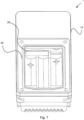
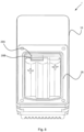
- the rodent trap 1 may comprise a battery compartment 26, as schematically illustrated in e.g. Fig. 7 , which may hold batteries for powering e.g. the sensor 13, 14, and/or the wireless transmitter and/or receiver 50, 50'.
- the battery compartment 26 may be accessible from underneath the rodent trap 1, or in other examples from above the rodent trap 1.
- the sensor 13, 14, and/or the wireless transmitter and/or receiver 50, 50' may have their own built-in battery.
- a connection port 27 is also illustrated which may allow for communication with internal components such as a PCB (printed circuit board), the sensor 13, 14, and/or the wireless transmitter and/or receiver 50, 50', of the rodent trap 1.
- connection port 27 may also allow for charging the batteries, either in the battery compartment 26 or built in batteries. In some examples, the connection port 27 may allow for externally powering rodent trap 1, if there are no batteries in the rodent trap 1.
- the connection port 27, as well as the rodent trap 1 as a whole may be classified according to IP class 67 or any other suitable IP class that allows for the rodent trap 1 to be placed in e.g. humid, wet and dusty conditions.
- Fig. 7 Illustrated in Fig. 7 is a bottom view of the rodent trap 1 and an example of the battery compartment 26 of the rodent trap 1.
- three batteries fit in the battery compartment 26.
- the number and type of batteries may be different depending on e.g. the power requirement of the sensor 13, 14, and/or the wireless transmitter and/or receiver 50, 50'.
- the batteries may be based on lithium, alkaline or other types of battery technologies.
- the rodent trap 1 may comprise a removable battery contact 28, illustrated in the example of Fig. 7 , which may be in electric connection with electrical components of the rodent trap 1, such as the sensor 13, 14, and/or the wireless transmitter and/or receiver 50, 50'.
- a removable battery contact 28 it is possible to make the rodent trap 1 more compact since components that requires only temporary access can be hidden behind the removable battery contact 28 and do not need a designated open access to the outside on the rodent trap 1.
- FIG. 8 Illustrated in Fig. 8 is a bottom view of the rodent trap 1 and an example of two components having connectors 29A and 29B facing out into the battery compartment 26.
- Such components could be a USB (Universal Serial Bus) connector, a SIM (Subscriber identity module) card holder, a power charger connector and/or a PCB connector.
- USB Universal Serial Bus
- SIM Subscriber identity module
- Example 1 A rodent trap (1) comprising
- Example 2 A rodent trap according to example 1, wherein the trigger member is configured to assume
- Example 3 A rodent trap according to example 2, wherein the trigger member is resiliently movable from the second position to the third position upon application of a force (F) on the trigger member towards the base, whereby the trigger member is biased to move from the third position to the second position when the force is removed.
- F a force
- Example 4 A rodent trap according to example 2 or 3, wherein the kill bar moves the trigger member from the first position to the second position when the kill bar moves from the armed position to the unloaded position.
- Example 5 A rodent trap according to any of examples 1 - 4, wherein the sensor comprises a magnetic sensor.
- Example 6 A rodent trap according to example 5, wherein the magnetic sensor comprises a magnet (13) and a magnetic sensor unit (14), wherein the trigger member comprises the magnet, and the base comprises the magnetic sensor unit, wherein the magnetic sensor is configured to detect at least three different separations between the magnet and the magnetic sensor unit corresponding to said at least three different distances.
- Example 7 A rodent trap according to example 6, wherein the trigger member comprises an extension (15), wherein the extension comprises the magnet.
- Example 8 A rodent trap according to any of examples 5 - 7, wherein the magnetic sensor comprises a Hall effect sensor or a reed switch.
- Example 9 A rodent trap according to any of examples 2 - 4, wherein the sensor is configured to relate a first trigger distance (A 1 ) of the at least three different distances to said first position and the ready state of the rodent trap.
- Example 10 A rodent trap according to any of examples 2 - 4, 9, wherein the sensor is configured to relate a second trigger distance (A 2 ) of the at least three different distances to said third position and the caught state of the rodent trap.
- Example 11 A rodent trap according to any of examples 2 - 4, 9 - 10, wherein the sensor is configured to relate a third trigger distance (A 3 ) of the at least three different distances to said second position and the sprung empty state of the rodent trap.
- Example 12 A rodent trap according to any of examples 1 - 11, comprising a wireless transmitter (50), the wireless transmitter is in communication with the sensor and is configured to transmit any of the at least three different distances to a receiver (110), and/or transmit any of a ready state, a sprung empty state and a caught state of the rodent trap associated with the at least three different distances to a receiver (110).
- Example 13 A method (200) for determining a ready state, a sprung empty state and a caught state of a rodent trap (1) comprising a base (10), a kill bar (11) and a trigger member (12) arranged between the base and the kill bar such that when the trigger member is activated the kill bar is released and traps or kills a rodent, the method comprising detecting (210) at least three different distances (A 1 , A 2 , A 3 ) between the trigger member and the base.
- Example 14 A method according to example 13, comprising
- Example 15 A method according to example 13 or 14, comprising
- Example 16 A method according to example 15, comprising
- Example 17 A method according to any of examples 13 - 16, comprising transmitting (250) any of the at least three different distances to a receiver (110), and/or transmitting (250') any of the ready state, the sprung empty state and the caught state of the rodent trap associated with the at least three different distances to a receiver (110).
- Example 18 A rodent trap system (100) comprising
- Example 19 A rodent trap system according to example 18, wherein the at least one receiver comprises a mobile phone, a computer, a webserver and/or a tablet.
Landscapes
- Life Sciences & Earth Sciences (AREA)
- Pest Control & Pesticides (AREA)
- Engineering & Computer Science (AREA)
- Insects & Arthropods (AREA)
- Wood Science & Technology (AREA)
- Zoology (AREA)
- Environmental Sciences (AREA)
- Catching Or Destruction (AREA)
- Physics & Mathematics (AREA)
- General Physics & Mathematics (AREA)
Abstract
Description
- The present invention relates to a rodent trap. More specifically the present invention relates to a rodent trap of a snap type comprising a sensor to detect states of the trap.
- There are different types of traps available today, such as mazes or cages to use when trying to get rid of rodents. Another type of rodent trap is a snap trap. The snap trap is designed to trap and kill a rodent between a spring loaded bar, here referred to as a kill bar, and a base of the trap.
- Commonly these traps are made for mice or rats. The main difference between a trap made for rats and a trap made for mice is that rat traps are larger and made such that the bar hits the rat with a greater force than the mouse in the mouse trap.
- A problem with these traps is that they might fail in trapping or killing a rodent which has triggered the trap. A rodent may be fast enough to escape the trap before being trapped by the kill bar. A rodent may also be so large that even if it is hit by the kill bar it is not killed or not even trapped by the rodent trap.
- Thus, improvements to rodent traps which allows for confirming the trapping or killing of the rodent, if the trap has sprung empty or if the trap is armed is desirable.
- It is, therefore, an object of the present invention to overcome or alleviate the above described problems.
- One objective is to provide a rodent trap which is robust and reliable in determining an armed ready state, a sprung empty state and if a rodent has been caught in a caught state thereof.
- One or more of these objectives, and other objectives that may appear from the description below, are at least partly achieved by means of a rodent trap according to the independent claims, embodiments thereof being defined by the dependent claims.
- According to a first aspect, a rodent trap is provided comprising a base, a kill bar, wherein the kill bar is pivotably connected to the base, a trigger member, wherein the trigger member is pivotably connected to the base and arranged between the base and the kill bar such that when the trigger member is activated the kill bar is released and traps or kills a rodent, the rodent trap comprises a sensor configured to detect at least three different distances (A1, A2, A3) between the trigger member and the base.
- According to a second aspect, a method is provided for determining a ready state, a sprung empty state and a caught state of a rodent trap comprising a base, a kill bar and a trigger member arranged between the base and the kill bar such that when the trigger member is activated the kill bar is released and traps or kills the rodent, the method comprising detecting at least three different distances (A1, A2, A3) between the trigger member and the base.
- According to a third aspect, a rodent trap system is provided comprising a plurality of rodent traps, the rodent trap comprising a base, and a kill bar, wherein the kill bar is pivotably connected to the base, a trigger member, wherein the trigger member is pivotably connected to the base and arranged between the base and the kill bar such that when the trigger member is activated the kill bar is released and traps a rodent, a sensor configured to detect at least three different distances (A1, A2, A3) between the trigger member and the base, a wireless transmitter in communication with the sensor and being configured to transmit any of the at least three different distances to at least one receiver, and/or transmit any of a ready state, a sprung empty state and a caught state of the rodent trap associated with the at least three different distances to at least one receiver, the rodent trap system comprising said at least one receiver.
- Further examples of the disclosure are defined in the dependent claims, wherein features for the first aspect may be implemented for the second and subsequent aspects, and vice versa.
- Having a sensor configured to detect at least three different distances between the trigger member and the base provides for a robust and reliable detection of different states of the rodent trap, since the position of the trigger member can be accurately determined, where said position is indicative of whether a rodent has been caught or not after the trap has been triggered.
- Some examples of the disclosure provide for a more robust and reliable detection of a ready state, a sprung empty state and a caught state of a rodent trap.
- Some examples of the disclosure provide for a facilitated and more efficient managing of a plurality of rodent traps in a rodent trap system.
- Still other objectives, features, aspects and advantages of the present disclosure will appear from the following detailed description, from the attached claims as well as from the drawings.
- It should be emphasized that the term "comprises/comprising" when used in this specification is taken to specify the presence of stated features, integers, steps or components but does not preclude the presence or addition of one or more other features, integers, steps, components or groups thereof.
- These and other aspects, features and advantages of which examples of the invention are capable of will be apparent and elucidated from the following description of examples of the present invention, reference being made to the accompanying drawings, in which;
-
Fig. 1 is a schematic illustration, in a perspective view of a rodent trap comprising a sensor, according to one example; -
Fig. 2 is a schematic illustration, in a top view of a rodent trap, according to one example; -
Figs. 3A-G are schematic illustrations, in side views of a rodent trap having three different distances between a base and a trigger member thereof, for different states of the rodent trap, according to examples of the disclosure; -
Fig. 4 is a schematic illustration, in a perspective view of a rodent trap comprising a sensor and a wireless transmitter, according to one example; -
Fig. 5A is a flow chart of a method for determining a ready state, a sprung empty state and a caught state of a rodent trap, according to one example; -
Figs. 5B-E are further flow charts of a method for determining a ready state, a sprung empty state and a caught state of a rodent trap, according to examples of the disclosure; -
Fig. 5F is a schematic illustration, in a schematic view of an electronic communication between a sensor, a transmitter of a rodent trap, and a remote receiver, according to one example; -
Fig. 6 is a schematic view of a rodent trap system comprising rodent traps and at least one receiver, according to one example; -
Fig. 7 is a schematic illustration, in a bottom view of a battery compartment of a rodent trap comprising a removable contact of the rodent trap, according to one example; and -
Fig. 8 is a schematic illustration, in a bottom view of a battery compartment of a rodent trap comprising additional connectors behind a removable contact, according to one example. - Embodiments of the invention will now be described more fully hereinafter with reference to the accompanying drawings, in which some, but not all, embodiments of the invention are shown. The invention may be embodied in many different forms and should not be construed as limited to the embodiments set forth herein.
-
Fig. 1 is a schematic perspective view of an example of arodent trap 1 comprising abase 10 and akill bar 11. Thekill bar 11 is pivotably connected to thebase 10 by aconnection bar 20 extending across thebase 10 essentially in parallel with thekill bar 11. Thekill bar 11 is also connected to a spring (not shown), for spring loading of the kill bar.Fig. 1 shows an armed ready state of therodent trap 1 where therodent trap 1 has been set by forcing thekill bar 11 against the spring and locked in place by alocking mechanism 21. The example inFig. 1 shows thelocking mechanism 21 engaging with an angled extension bar 11' of thekill bar 11, where the angled extension bar 11' locks into a notch 21' of thelocking mechanism 21. It should be understood however that thekill bar 11 may be locked into place in an armed ready state of therodent trap 1 by various locking mechanisms. - The
rodent trap 1 comprises atrigger member 12. Thekill bar 11 is releasable from thelocking mechanism 21 by thetrigger member 12. Thetrigger member 12 is engaged with thelocking mechanism 21 so that pivoting of thetrigger member 12 unlocks thelocking mechanism 21 from an armed position when holding thekill bar 11 in the ready state. Thus, thetrigger member 12 is pivotably connected to thebase 10 and arranged between thebase 10 and thekill bar 11 such that when thetrigger member 12 is activated by the rodent, thelocking mechanism 21 is released which thereby releases thekill bar 11 which in turn traps or kills the rodent. Thekill bar 11 may e.g. be released by releasing the angled extension bar 11' from notch 21'. Thus, the effect of the rodent triggering thetrigger member 12 is that thekill bar 11 quickly and forcibly moves towards thebase 10 and thus hits and traps the rodent against thebase 10. Ideally, thekill bar 11 will hit the rodent with a force which is enough to produce an impulse which kills the rodent instantaneously. - A bait is usually placed on or in a
bait holder 23 which may be arranged on or near thetrigger member 12 in order to attract a rodent towards thetrigger member 12. When a rodent comes into contact with thetrigger member 12 it should pivot thetrigger member 12 which unlocks thelocking mechanism 21 and thus releases thekill bar 11 as explained above. - The
rodent trap 1 comprises asensor trigger member 12 and thebase 10.Figs. 3A-G show examples of such detected distances (A1, A2, A3) between thetrigger member 12 and thebase 10. Thesensor trigger member 12 relative to thebase 10 as thetrigger member 12 pivots with respect to thebase 10 during the operational states of therodent trap 1, as exemplified inFigs. 3A-G .Fig. 1 andFigs. 3A-G show examples where thesensor rodent trap 1, essentially opposite the end where the rodent is trapped by thekill bar 11. It should be understood however that thesensor base 10 andtrigger member 12 to detect at least three different distances (A1, A2, A3) between thetrigger member 12 and the base 10 while providing for the advantageous benefits as further described below. Increasing the distance between thesensor trigger member 12, which may be the arranged at or adjacent theconnection bar 20 in some examples, provides for increasing the length of the range of motion of thetrigger member 12 relative to thebase 10. This may provide for a facilitated distinguishing and detecting of the at least three different distances (A1, A2, A3), and thus for a more accurate detection of the states of therodent trap 1. - The
sensor trigger member 12 and thebase 10, e.g. one or more of an electrical sensor, mechanical sensor, electro-mechanical sensor, optical sensor, or a magnetic sensor. Thesensor more sensor components base 10 and/or on thetrigger member 12.Fig. 1 andFigs. 3A-G show examples where thesensor sensor components trigger member 12 and thebase 10, respectively. In one example, afirst sensor component 13, arranged on thetrigger member 12, may be arranged essentially opposite asecond sensor component 14 arranged on thebase 10. The first andsecond sensor components second sensor components trigger member 12 pivots relative to thebase 10. At least three different distances (A1, A2, A3) between thetrigger member 12 and the base 10 may thus be determined as the amount of said separation varies. In some examples the first orsecond sensor component second sensor component trigger member 12 or the base 10 which is chosen as a passive detection point for e.g. a proximity sensor, such as an optical sensor, configured to detect the at least three different distances (A1, A2, A3) between thetrigger member 12 and thebase 10. The passive detection point be in such case be a flat surface in the material from which thetrigger member 12 orbase 10 is formed. Thefirst sensor component 13 and thesecond sensor component 14 may comprise such passive detection point and proximity sensor, respectively, in one example. - In one example, the
sensor magnetic sensor magnetic sensor magnet 13 as afirst sensor component 13 and amagnetic sensor unit 14 as asecond sensor component 14, as described further below. - Having a
sensor trigger member 12 and thebase 10 provides for a robust and reliable detection of different states of the rodent trap, since the position of thetrigger member 12 can be accurately determined, where said position is indicative of whether a rodent has been caught or not after the trap has been triggered. Having thesensor trigger member 12 alleviates the need for having detection capability directly on the position of thekill bar 11 in sensor-based rodent traps. This allows for optimizing the function of thekill bar 11 separately, e.g. with respect to speed, force, or re-useability, without having concern of providing detection functionality. A moreefficient rodent trap 1 is thus provided with a more reliable detection of the different states of the rodent trap. - Detection of at least three different distances (A1, A2, A3) between the
trigger member 12 and thebase 10 is exemplified inFigs. 3D-G .Fig. 3D shows an armed ready state of therodent trap 1, i.e. thekill bar 11 has been forced to its armed position and locked by the locking mechanism 21 (Fig. 1 ), where thesensor trigger member 12 and thebase 10. Thetrigger member 12 assumes a first position (p1) in this state, as further denoted inFig. 3D .Fig. 3A shows an alternative side-view of this state of therodent trap 1. -
Fig. 3E shows a state of therodent trap 1 where thekill bar 11 is in an unloaded position and in abutment with thebase 10. This state corresponds to a sprung empty state of therodent trap 1, i.e. thetrigger member 12 has been triggered, moving thekill bar 11 forcibly down towards thebase 10, but no rodent is trapped by thekill bar 11. Thekill bar 11 cause movement of thetrigger member 12 from the first position (p1) to a second position (p2) when thekill bar 11 moves from the armed position (Fig. 3D ) to the unloaded position inFig. 3E . Thesensor trigger member 12 and thebase 10, which accordingly is different from the distance denoted A1 inFig. 3D .Fig. 3C shows an alternative side-view of this state of therodent trap 1. - The
trigger member 12 is movable relative thekill bar 11 in a direction towards the base 10 from the second position (p2) to a third position (p3) while thekill bar 11 is in said unloaded position, as schematically illustrated inFig. 3F . Thus, a gap (d) can be arranged in between the second (p2) and third positions (p3) of thetrigger member 12 which accommodates at least part of the rodent (R) when trapped in therodent trap 1, as further schematically illustrated inFig. 3G . The position of thetrigger member 12 in the second position (p2) is schematically illustrated inFig. 3G with dashed lines for comparison.This is referred to as the caught state of therodent trap 1. Thesensor trigger member 12 and thebase 10, which is different from the distance denoted A3 inFig. 3E since thetrigger member 12 has moved to the third position (p3), e.g. by a rodent (R) pushing down on thetrigger member 12 as exemplified inFig. 3G .Fig. 3B shows an alternative side-view of this state of therodent trap 1. It should be understood that while thetrigger member 12 is movable relative thekill bar 11 from the second position (p2) to the third position (p3) while thekill bar 11 is in said unloaded position, as described with reference toFig. 3F , the trapping of a rodent (R) under thekill bar 11, as shown inFig. 3G , can alter the position of thekill bar 11 depending on how large part of the rodent is trapped. Regardless, having atrigger member 12 which is movable from the second position (p2) to the third position (p3) as described above provides for the detection of the third distance A3 when a rodent has been trapped, independent on the current position of the kill bar 11 (inFig. 3G ). - The
trigger member 12 may be resiliently movable from the second position (p2) to the third position (p3) upon application of a force (F) on thetrigger member 12 towards thebase 10, as illustrated inFig. 3F . Thus, thetrigger member 12 may be biased to move from the third position (p3) to the second position (p2) when the force (F) is removed. The provides for having thetrigger member 12 returning to the second position (p2) if a rodent first depresses thetrigger member 12 to the third position (p3) but later manages to escape from underneath thekill bar 11. Thesensor rodent trap 1, and may additionally provide the information that a rodent was first trapped but then escaped. - The
sensor rodent trap 1. Thesensor rodent trap 1. Further, thesensor rodent trap 1. -
Fig. 2 is a top view of an example of therodent trap 1. From this view it can be seen that thekill bar 11 may be formed in such a way that thekill bar 11 extends outside of thetrigger member 12 on aleft side 30a andright side 30b of thetrigger member 12. I.e. the inner separation betweenarms horizontal kill bar 11 is wider than the width (w) of thetrigger member 12. Thekill bar 11, or thearms edges trigger member 12, without having thearms trigger member 12.Edges Fig. 2 . Thus, thekill bar arms aforementioned edges Figs. 1 - 3 when activated and forced down by a kill bar spring (not shown). Theedges kill bar 11 toward thebase 10. Further, when thekill bar 11, and/orarms edges reference numeral 11 inFig. 1 ), extending in parallel with atop edge 25b of thebase 10, and in some examples interior to thetop edge 25b, will push down on thetrigger member 12, as illustrated and described above with reference toFig. 3E and the second position (p2) of thetrigger member 12. Thetrigger member 12 may be biased to move towards the first position (p1) in some examples. This provides for facilitating the arming of therodent trap 1 in the ready position (Fig. 3D ). In case thetrigger member 12 has such bias, thekill bar 11 keeps thetrigger member 12 from moving towards the first position (p1) when pushing down on the trigger member 12 (Fig. 3E ). - The bias of the
trigger member 12 may be provided by a trigger spring (not shown), which urges thetrigger member 12 upward back to the first position (p1). In an example, thetrigger member 12 may not be connected to the trigger spring but instead thetrigger member 12 strives towards the first position (p1) due to thetrigger member 12 having a larger mass on alocking mechanism side 33 of theconnection rod 20 than towards aside 34 of thetrigger member 12 where the rodent triggers the trigger member 12 (see references inFig. 3D ). Thus, thelocking mechanism side 33 of thetrigger member 12 may act as a counterweight to theopposite side 34 of thetrigger member 12. So, thelocking mechanism side 33 is heavier, and this will make thetrigger member 12 return to the first position (p1) (Fig. 3D ) unless thekill bar 11 is pushing thetrigger member 12 down (Fig. 3E ). - A top of the
kill bar 11 may in some examples extend above thetrigger member 12 alongedge 25b. Thekill bar 11 or thetrigger member 12 may in those examples comprise a linkage member that mechanically connects thekill bar 11 and thetrigger member 12 so that thetrigger member 12 is kept in a position corresponding to the second position (p2). Regardless, thetrigger member 12 is configured to move from the second position (p2) to the third position (p3), to accommodate a rodent, as described above with reference toFigs. 3F-G , independent on how the pivot angle of thetrigger member 12 is restricted to the second position (p2) at the sprung empty state of therodent trap 1. - In some examples the
edges 25a-c of thebase 10 comprises a sharp elevation from thebase 10. Alternatively, or in addition, theedges 25a-c comprises teeth and/or grooves. Therodent trap 1 may only have teeth/grooves and/or sharp elevations along oneedge 25a-c. Teeth/grooves and/or sharp elevations may be mixed or combined alongdifferent edges 25a-c. In one example theedges 25a-c do not comprise teeth/grooves, or sharp elevations, but only blunt edges. - The
sensor magnetic sensor trigger member 12 comprises amagnet 13 and thebase 10 comprises amagnetic sensor unit 14. Themagnetic sensor unit 14 is configured to detect the magnetic field from themagnet 13. The magnetic field varies depending on the amount of separation between themagnet 13 and themagnetic sensor unit 14. Themagnet 13 and themagnetic sensor unit 14 may be arranged essentially opposite eachother on thetrigger member 12 and thebase 10, respectively. Themagnetic sensor trigger member 12 and thebase 10. In an example, themagnetic sensor magnetic sensors magnet 13 is arranged on thebase 10 and themagnetic sensor unit 14 is arranged on thetrigger member 12. - In an example where the
magnetic sensor rodent trap 1 may be chosen to correspond to at least the number of distances (A1, A2, A3) that should be sensed minus one. I.e. if three distances (A1, A2, A3) need to be distinguished, 3-1=2 reed switches suffices to detect the three distances (A1, A2, A3). This is due to the reed switch being an on-off switch. - Having a
magnetic sensor rodent trap 1 is in the ready state to catch a rodent, if the trap is in a sprung empty state, i.e. in false-positive state, or in the caught state when the rodent has been caught. At the same time, amagnetic sensor robust rodent trap 1 with minimal maintenance. - The
sensor trigger member 12 and thebase 10, e.g. one or more of an electrical sensor, mechanical sensor, electro-mechanical sensor, or an optical sensor. - In an example and to further increase a distance between the three different trigger distances (A1, A2, A3), the
trigger member 12 comprises anextension 15. Theextension 15 may comprise themagnet 13, as schematically illustrated in e.g.Fig. 2 andFig. 3E . By having theextension 15, the distance between the three different trigger distances (A1, A2, A3) is increased and thus also aids in facilitating distinguishing and detecting the three different distances (A1, A2, A3) by themagnetic sensor - The detection of the different distances (A1, A2, A3) is further exemplified with reference to
Figs. 3A-C . Thesensor magnetic sensor Fig. 3A is a side view of an example of therodent trap 1 when there is a relatively small distance A1 between themagnet 13 and themagnetic sensor unit 14, i.e. the trap is in the ready state. In this ready state, thetrigger member 12 and themagnet 13 may be arranged in a parallel or almost parallel position relative to thebase 10. In the ready state themagnet 13 is arranged in close proximity to themagnetic sensor unit 14 and the first distance A1 is thus very small, or themagnet 13 can even abut thebase 10. Themagnetic sensor unit 14 is configured to relate this first distance A1 to the ready state of therodent trap 1. The ready state means that thekill bar 11 is locked in place by thelocking mechanism 21 and thus can be activated when the rodent activates thetrigger member 12. - Illustrated in
Fig. 3B is a side view of an example of therodent trap 1 when there is a relatively large distance A2 between themagnet 13 and themagnetic sensor unit 14. Therodent trap 1 is here in the caught state, corresponding to the description with respect toFigs. 3F-G above. Thetrigger member 12 and themagnet 13 may here be arranged in a maximum or close to maximum tilted position relative to thebase 10. Themagnet 13 may thus be arranged at the largest distance A2 away from themagnetic sensor unit 14. Themagnetic sensor unit 14 is configured to relate this second distance A2 to the caught state of therodent trap 1. Hence, therodent trap 1 has caught the rodent in therodent trap 1. - In the illustrated examples, the
trigger member 12 may pivot around theconnection bar 20. In other examples, thetrigger member 12 may pivot around other parts of therodent trap 1. Thus, at the end of therodent trap 1 withedges 25a-25c, an end of thetrigger member 12 may be fully depressed to abut thebase 10, when in the maximum or close to maximum tilted state. At the opposite end of thetrigger member 12, themagnet 13 together with thebase 10, and/orlocking mechanism 21 may stop thetrigger member 12 from tilting in an opposite direction, so that thetrigger member 12 may assume a parallel position with respect to thebase 10, i.e. in the ready state. - After the
locking mechanism 21 has disengaged thetrigger member 12, and thekill bar 11 has been released, thetrigger member 12 may be kept in a somewhat tilted position by thekill bar 11, as illustrated in e.g.Fig. 3E . In order to get thetrigger member 12 to fully tilt, and in some examples touch thebase 10, and thus having themagnet 13 andmagnetic sensor unit 14 at the largest or maximum distance A2 something need to be placed in between thekill bar 11 and thetrigger member 12. Thus, the largest distance A2 is only realized when the rodent is actually caught and placed between thekill bar 11 and thetrigger member 12, as exemplified inFig. 3G . - Illustrated in
Fig. 3C is a side view of an example of therodent trap 1 when there is a medium distance A3 between themagnet 13 and themagnetic sensor unit 14, therodent trap 1 is in the false-positive or sprung empty state. Thetrigger member 12 and themagnet 13 is arranged in a slightly tilted position relative to thebase 10 and themagnet 13 is arranged at the distance A3, which is between the first A1 and second distance A2, to themagnetic sensor 14. This is the same position of thetrigger member 12 as discussed above in relation toFig. 2 , i.e. when thekill bar 11 pushes on thetrigger member 12. Themagnetic sensor unit 14 is configured to relate this third distance A3 to the false-positive or sprung empty state of therodent trap 1. In the false-positive state the rodent or something have triggered thetrigger member 12 to unlock thelocking mechanism 21 and thus sending thekill bar 11 downward to theedges kill bar 11,edges trigger member 12, as discussed above in relation toFig. 2 andFigs. 3F-G , thetrigger member 12 will not be tilted in the maximum tilted position. Thus, if thetrigger member 12 triggers thelocking mechanism 21 to release thekill bar 11 but there is no rodent or something else placed between thekill bar 11 and thebase 10, thetrigger member 12 will thus be placed in the slightly tilted position, as seen inFig. 3C , or the position p2 inFig. 3E , different from the maximum tilted position, as seen inFig. 3B , or the position p3 inFig. 3G . - In some examples, the
magnet 13 and/ormagnetic sensor unit 14 is arranged on or attached to thetrigger member 12, or anyextension 15 of thetrigger member 12. The attachment can be performed by e.g. gluing themagnet 13 to thetrigger member 12. - In an example, there may be two
connection rods 20 making up theconnection bar 20, one on each end of thekill bar 11. In these cases, there might be two killbars 11, each connected torespective connection rod 20. In these types ofrodent traps 1, the kill bars 11 may be placed next to each other and sometimes joined together by a weld. In some examples, thekill bar 11 and theconnection rods 20 are made from one continuous piece which is bent into the shape of thekill bar 11 and connection rod(s) 20. - Illustrated in e.g.
Fig. 4 is an example wherein therodent trap 1 comprises awireless transmitter 50, exemplified by an antenna denoted withreference numeral 50. In some examples therodent trap 1 may also comprise a wireless receiver, exemplified by an antenna denoted with reference numeral 50' inFig. 4 . Thewireless transmitter 50 is in communication with thesensor receiver 50, 50', may be any of a cellular unit such as GSM (Global System for Mobile Communications) unit, 3G, 4G or 5G unit, a wireless network unit, a Bluetooth unit or the like. In an example, therodent trap 1 comprises a sim card holder for communication with the cellular unit. In some examples the wireless transmitter and/orreceiver 50, 50', may be embedded in thebase 10 and may communicate withexternal antennas 50, 50'. In some examples the transmitter and/orreceiver 50, 50', may be embedded with theantennas 50, 50'. In some examples oneantenna 50 may be utilized for the wireless communication. Alternatively, a plurality ofantennas 50, 50', may be utilized, depending on reception needs. - The
wireless transmitter 50 may be configured to transmit any of the at least three different distances (A1, A2, A3) to areceiver 110, such as aremote receiver 110, as schematically illustrated inFig. 6 . Alternatively, or in addition, thewireless transmitter 50 is may be configured to transmit any of a ready state, a sprung empty state and a caught state of therodent trap 1 associated with the at least three different distances (A1, A2, A3), as described above, to aremote receiver 110. - Hence, the
wireless transmitter 50 allows for communicating the detected state, i.e. the armed ready state, the caught state, or the false-positive/sprung empty state, and/or the distances (A1, A2, A3), to areceiver 110. Thereceiver 110 can e.g. be a mobile phone, a computer, lap-top, a tablet, a webserver or the like that is configured to receive the detected state and/or distance (A1, A2, A3). This communication can be performed by sending and/or receiving a signal and/or data that comprises the detected state and/or distance (A1, A2, A3). -
Fig. 5A is a flow chart of amethod 200 for determining a ready state, a sprung empty state and a caught state of arodent trap 1. Therodent trap 1 comprises abase 10, akill bar 11 and atrigger member 12 arranged between the base 10 and thekill bar 11 such that when thetrigger member 12 is activated thekill bar 11 is released and traps or kills the rodent. Themethod 200 comprises detecting 210 at least three different distances (A1, A2, A3) between thetrigger member 12 and thebase 10. Themethod 200 thus provides for the advantageous benefits as described for therodent trap 1 in relation toFigs. 1 - 4 above. Themethod 200 provides for a robust and reliable detection of different states of therodent trap 1. -
Figs. 5B-E are further flow charts of amethod 200 for determining a ready state, a sprung empty state and a caught state of arodent trap 1. Themethod 200 may comprise detecting 220 a first position (p1) of thetrigger member 12 when thekill bar 11 is in an armed position in the ready state of therodent trap 1. Themethod 200 may comprise relating 221 a first trigger distance (A1) of the at least three different distances (A1, A2, A3) to said first position (p1) and the ready state of the rodent trap 1 (Fig. 5B ). - The
method 200 may comprise detecting 230 a second position (p2) of thetrigger member 12 when the kill bar is in an unloaded position and in abutment with the base 10 corresponding to the sprung empty state of therodent trap 1. Themethod 200 may comprise relating 231 a third trigger distance (A3) of the at least three different distances (A1, A2, A3) to said second position (p2) and the sprung empty state of the rodent trap 1 (Fig. 5C ). - The
method 200 may comprise detecting 240 a third position (p3) of thetrigger member 12, whereupon thetrigger member 12 is movable relative thekill bar 11 in a direction towards the base 10 from the second position (p2) to said third position (p3) while thekill bar 11 is in said unloaded position. A gap (d) arranged in between the second and third positions (p2, p3) of thetrigger member 12 may accommodate part of a rodent when trapped in therodent trap 1, in the caught state thereof. Themethod 200 may comprise relating 241 a second trigger distance (A2) of the at least three different distances (A1, A2, A3) to said third position and the caught state of the rodent trap 1 (Fig. 5D ). - The
method 200 may comprise transmitting 250 any of the at least three different distances (A1, A2, A3) to areceiver 110, and/or transmitting 250' any of the ready state, the sprung empty state and the caught state of therodent trap 1 associated with the at least three different distances (A1, A2, A3) to areceiver 110. - Illustrated in
figure 5F is an example wherein theremote receiver 110 may be in direct communication with the wireless receiver and/ortransmitter 50, 50', which in turn is in communication with thesensor remote receiver 110, such as a mobile phone or computer, may communicate with the wireless receiver and/ortransmitter 50, 50' of therodent trap 1 via different types of relays such as a cellular tower, one or more webserver, apps, WIFI-protocols and so on. - In an example of the communication of the detected distances (A1, A2, A3) between the
rodent trap 1 and theremote receiver 110, themagnetic sensor wireless transmitter 50, and then further to a cellular tower which relays the communication further to theremote receiver 110, such as amobile phone 110. Themobile phone 110 can be programmed to show an alert that displays a given name of therodent trap 1, a location of therodent trap 1 and the detected distance A3, and/or the state related to A3, i.e. the false-positive/sprung empty state of therodent trap 1. - In some examples, other parameters related to the
rodent trap 1 can also be comprised in the communication to theremote receiver 110, such as temperature, humidity, sound alerts, or settings of therodent trap 1 related to e.g. firmware, light commands for controlling connected light sources, error codes and so on. In some examples, the communication is only one way, i.e. thereceiver 110 only receives communication. In other examples, the communication is a two-way communication where theremote receiver 110 can send communication to a wireless receiver 50' of therodent trap 1. - The
rodent trap 1 may comprise anotification unit 35 configured to emit an audible alert, and/or a visual alert to a user. Anotification unit 35 is schematically indicated in the illustration ofFig. 2 . The audible and/or visual alert may be associated with any one of the ready state, the sprung empty state, and the caught state of therodent trap 1. Thenotification unit 35 may thus be in communication with thesensor Fig. 5F . Each of the aforementioned states may be associated with a different audible and/or visual notification signal which notifies the user of the different states. - In an example illustrated in
Fig. 6 , a plurality ofrodent traps 1 are combined into arodent trap system 100. Therodent trap system 100 comprises at least oneremote receiver 110. Therodent trap 1 comprises awireless transmitter 50 in communication with thesensor remote receiver 110. Alternatively, or in addition, thewireless transmitter 50 is configured to transmit any of a ready state, a sprung empty state and a caught state of therodent trap 1 associated with the at least three different distances (A1, A2, A3) to at least onereceiver 110. By having therodent trap 1 and/or thesystem 100 configured to send and/or receive the detected state and/or distance (A1, A2, A3) from at least onerodent trap 1 it is possible to minimize any time spent on checking the rodent traps 1 if they are triggered. It allows also for sending out the best fitted person for the job depending on the detected state of therodent trap 1. For example, if the detected state of therodent trap 1 is the false-positive/sprung empty state any one close to therodent trap 1 may arm therodent trap 1 again. If the detected state is the caught state, then a pest controller could be sent to therodent trap 1. - The
rodent trap 1 may comprise abattery compartment 26, as schematically illustrated in e.g.Fig. 7 , which may hold batteries for powering e.g. thesensor receiver 50, 50'. Thebattery compartment 26 may be accessible from underneath therodent trap 1, or in other examples from above therodent trap 1. In other examples thesensor receiver 50, 50', may have their own built-in battery. In the illustrated example ofFig. 4 , aconnection port 27 is also illustrated which may allow for communication with internal components such as a PCB (printed circuit board), thesensor receiver 50, 50', of therodent trap 1. Theconnection port 27 may also allow for charging the batteries, either in thebattery compartment 26 or built in batteries. In some examples, theconnection port 27 may allow for externally poweringrodent trap 1, if there are no batteries in therodent trap 1. Theconnection port 27, as well as therodent trap 1 as a whole may be classified according to IP class 67 or any other suitable IP class that allows for therodent trap 1 to be placed in e.g. humid, wet and dusty conditions. - Illustrated in
Fig. 7 is a bottom view of therodent trap 1 and an example of thebattery compartment 26 of therodent trap 1. In this example three batteries fit in thebattery compartment 26. The number and type of batteries may be different depending on e.g. the power requirement of thesensor receiver 50, 50'. The batteries may be based on lithium, alkaline or other types of battery technologies. - The
rodent trap 1 may comprise aremovable battery contact 28, illustrated in the example ofFig. 7 , which may be in electric connection with electrical components of therodent trap 1, such as thesensor receiver 50, 50'. By having aremovable battery contact 28, it is possible to make therodent trap 1 more compact since components that requires only temporary access can be hidden behind theremovable battery contact 28 and do not need a designated open access to the outside on therodent trap 1. - Illustrated in
Fig. 8 is a bottom view of therodent trap 1 and an example of twocomponents having connectors battery compartment 26. Such components could be a USB (Universal Serial Bus) connector, a SIM (Subscriber identity module) card holder, a power charger connector and/or a PCB connector. - From the description above follows that, although various examples of the invention have been described and shown, the invention is not restricted thereto, but may also be embodied in other ways within the scope of the subject-matter defined in the following claims.
- Example 1. A rodent trap (1) comprising
- a base (10),
- a kill bar (11), wherein the kill bar is pivotably connected to the base,
- a trigger member (12), wherein the trigger member is pivotably connected to the base and arranged between the base and the kill bar such that when the trigger member is activated the kill bar is released and traps or kills a rodent, the rodent trap further comprises
- a sensor (13, 14) configured to detect at least three different distances (A1, A2, A3) between the trigger member and the base.
- Example 2. A rodent trap according to example 1, wherein the trigger member is configured to assume
- a first position (p1) when the kill bar is in an armed position in a ready state of the rodent trap,
- a second position (p2) when the kill bar is in an unloaded position and in abutment with the base corresponding to a sprung empty state of the rodent trap,
- wherein the trigger member is movable relative the kill bar in a direction towards the base from the second position to a third position (p3) while the kill bar is in said unloaded position,
- whereby a gap (d) arranged in between the second and third positions of the trigger member accommodates part of the rodent when trapped in the rodent trap, in a caught state thereof.
- Example 3. A rodent trap according to example 2, wherein the trigger member is resiliently movable from the second position to the third position upon application of a force (F) on the trigger member towards the base, whereby the trigger member is biased to move from the third position to the second position when the force is removed.
- Example 4. A rodent trap according to example 2 or 3, wherein the kill bar moves the trigger member from the first position to the second position when the kill bar moves from the armed position to the unloaded position.
- Example 5. A rodent trap according to any of examples 1 - 4, wherein the sensor comprises a magnetic sensor.
- Example 6. A rodent trap according to example 5, wherein the magnetic sensor comprises a magnet (13) and a magnetic sensor unit (14), wherein the trigger member comprises the magnet, and the base comprises the magnetic sensor unit, wherein the magnetic sensor is configured to detect at least three different separations between the magnet and the magnetic sensor unit corresponding to said at least three different distances.
- Example 7. A rodent trap according to example 6, wherein the trigger member comprises an extension (15), wherein the extension comprises the magnet.
- Example 8. A rodent trap according to any of examples 5 - 7, wherein the magnetic sensor comprises a Hall effect sensor or a reed switch.
- Example 9. A rodent trap according to any of examples 2 - 4, wherein the sensor is configured to relate a first trigger distance (A1) of the at least three different distances to said first position and the ready state of the rodent trap.
- Example 10. A rodent trap according to any of examples 2 - 4, 9, wherein the sensor is configured to relate a second trigger distance (A2) of the at least three different distances to said third position and the caught state of the rodent trap.
- Example 11. A rodent trap according to any of examples 2 - 4, 9 - 10, wherein the sensor is configured to relate a third trigger distance (A3) of the at least three different distances to said second position and the sprung empty state of the rodent trap.
- Example 12. A rodent trap according to any of examples 1 - 11, comprising a wireless transmitter (50), the wireless transmitter is in communication with the sensor and is configured to
transmit any of the at least three different distances to a receiver (110), and/or transmit any of a ready state, a sprung empty state and a caught state of the rodent trap associated with the at least three different distances to a receiver (110). - Example 13. A method (200) for determining a ready state, a sprung empty state and a caught state of a rodent trap (1) comprising a base (10), a kill bar (11) and a trigger member (12) arranged between the base and the kill bar such that when the trigger member is activated the kill bar is released and traps or kills a rodent, the method comprising
detecting (210) at least three different distances (A1, A2, A3) between the trigger member and the base. - Example 14. A method according to example 13, comprising
- detecting (220) a first position (p1) of the trigger member when the kill bar is in an armed position in the ready state of the rodent trap,
- relating (221) a first trigger distance (A1) of the at least three different distances to said first position and the ready state of the rodent trap.
- Example 15. A method according to example 13 or 14, comprising
- detecting (230) a second position (p2) of the trigger member when the kill bar is in an unloaded position and in abutment with the base corresponding to the sprung empty state of the rodent trap,
- relating (231) a third trigger distance (A3) of the at least three different distances to said second position and the sprung empty state of the rodent trap.
- Example 16. A method according to example 15, comprising
- detecting (240) a third position (p3) of the trigger member, whereupon the trigger member is movable relative the kill bar in a direction towards the base from the second position to said third position (p3) while the kill bar is in said unloaded position,
- whereby a gap (d) arranged in between the second and third positions of the trigger member accommodates part of the rodent when trapped in the rodent trap, in the caught state thereof,
- relating (241) a second trigger distance (A2) of the at least three different distances to said third position and the caught state of the rodent trap.
- Example 17. A method according to any of examples 13 - 16, comprising
transmitting (250) any of the at least three different distances to a receiver (110), and/or transmitting (250') any of the ready state, the sprung empty state and the caught state of the rodent trap associated with the at least three different distances to a receiver (110). - Example 18. A rodent trap system (100) comprising
- a plurality of rodent traps (1), a rodent trap (1) of the plurality of rodent traps comprising
- a base (10),
- a kill bar (11), wherein the kill bar is pivotably connected to the base,
- a trigger member (12), wherein the trigger member is pivotably connected to the base and arranged between the base and the kill bar such that when the trigger member is activated the kill bar is released and traps a rodent,
- a sensor configured to detect at least three different distances (A1, A2, A3) between the trigger member and the base,
- a wireless transmitter (50) in communication with the sensor and being configured to transmit any of the at least three different distances to at least one receiver (110), and/or transmit any of a ready state, a sprung empty state and a caught state of the rodent trap associated with the at least three different distances to at least one receiver (110), the rodent trap system comprising said at least one receiver.
- Example 19. A rodent trap system according to example 18, wherein the at least one receiver comprises a mobile phone, a computer, a webserver and/or a tablet.
Claims (15)
- A rodent trap (1) comprisinga base (10),a kill bar (11), wherein the kill bar is pivotably connected to the base,a trigger member (12), wherein the trigger member is pivotably connected to the base and arranged between the base and the kill bar such that when the trigger member is activated the kill bar is released and traps or kills a rodent, the rodent trap further comprisesa sensor (13, 14) configured to detect at least three different distances (A1, A2, A3) between the trigger member and the base,wherein the trigger member is configured to move toa first position (p1) when the kill bar is in an armed position in a ready state of the rodent trap,a second position (p2) when the kill bar is in an unloaded position and in abutment with the base corresponding to a sprung empty state of the rodent trap,wherein the trigger member is movable relative the kill bar in a direction towards the base from the second position to a third position (p3) while the kill bar is in said unloaded position,whereby a gap (d) arranged in between the second and third positions of the trigger member accommodates part of the rodent when trapped in the rodent trap, in a caught state thereof.
- A rodent trap according to claim 1, wherein the trigger member is resiliently movable from the second position to the third position upon application of a force (F) on the trigger member towards the base, whereby the trigger member is biased to move from the third position to the second position when the force is removed.
- A rodent trap according to claim 1 or 2, wherein the kill bar moves the trigger member from the first position to the second position when the kill bar moves from the armed position to the unloaded position.
- A rodent trap according to any of claims 1 - 3, wherein the sensor comprises a magnetic sensor.
- A rodent trap according to claim 4, wherein the magnetic sensor comprises a magnet (13) and a magnetic sensor unit (14), wherein the trigger member comprises the magnet, and the base comprises the magnetic sensor unit, wherein the magnetic sensor is configured to detect at least three different separations between the magnet and the magnetic sensor unit corresponding to said at least three different distances.
- A rodent trap according to claim 5, wherein the trigger member comprises an extension (15), wherein the extension comprises the magnet.
- A rodent trap according to any of claims 4 - 6, wherein the magnetic sensor comprises a Hall effect sensor or a reed switch.
- A rodent trap according to any of claims 1 - 3, wherein the sensor is configured to relate a first trigger distance (A1) of the at least three different distances to said first position and the ready state of the rodent trap.
- A rodent trap according to any of claims 1 - 3, 8, wherein the sensor is configured to relate a second trigger distance (A2) of the at least three different distances to said third position and the caught state of the rodent trap.
- A rodent trap according to any of claims 1 - 3, 8 - 9, wherein the sensor is configured to relate a third trigger distance (A3) of the at least three different distances to said second position and the sprung empty state of the rodent trap.
- A rodent trap according to any of claims 1 - 10, comprising a wireless transmitter (50), the wireless transmitter is in communication with the sensor and is configured to
transmit any of the at least three different distances to a receiver (110), and/or transmit any of a ready state, a sprung empty state and a caught state of the rodent trap associated with the at least three different distances to a receiver (110). - A method (200) for determining a ready state, a sprung empty state and a caught state of a rodent trap (1) comprising a base (10), a kill bar (11) and a trigger member (12) arranged between the base and the kill bar such that when the trigger member is activated the kill bar is released and traps or kills a rodent, the method comprisingdetecting (210) at least three different distances (A1, A2, A3) between the trigger member and the base,detecting (220) a first position (p1) of the trigger member when the kill bar is in an armed position in the ready state of the rodent trap,detecting (230) a second position (p2) of the trigger member when the kill bar is in an unloaded position and in abutment with the base corresponding to the sprung empty state of the rodent trap, anddetecting (240) a third position (p3) of the trigger member, whereupon the trigger member is movable relative the kill bar in a direction towards the base from the second position to said third position (p3) while the kill bar is in said unloaded position,whereby a gap (d) arranged in between the second and third positions of the trigger member accommodates part of the rodent when trapped in the rodent trap, in the caught state thereof.
- A method according to claim 12, comprisingrelating (221) a first trigger distance (A1) of the at least three different distances to said first position and the ready state of the rodent trap, and/orrelating (231) a third trigger distance (A3) of the at least three different distances to said second position and the sprung empty state of the rodent trap, and/orrelating (241) a second trigger distance (A2) of the at least three different distances to said third position and the caught state of the rodent trap.
- A method according to claim 12 or 13, comprising
transmitting (250) any of the at least three different distances to a receiver (110), and/or transmitting (250') any of the ready state, the sprung empty state and the caught state of the rodent trap associated with the at least three different distances to a receiver (110). - A rodent trap system (100) comprising
a plurality of rodent traps (1) according to any of claims 1 - 11 and a wireless transmitter (50) in communication with the sensor and being configured to transmit any of the at least three different distances to at least one receiver (110), and/or transmit any of a ready state, a sprung empty state and a caught state of the rodent trap associated with the at least three different distances to at least one receiver (110), the rodent trap system comprising said at least one receiver, wherein the at least one receiver comprises a mobile phone, a computer, a webserver and/or a tablet.
Applications Claiming Priority (3)
| Application Number | Priority Date | Filing Date | Title |
|---|---|---|---|
| SE1930326A SE543735C2 (en) | 2019-10-11 | 2019-10-11 | A rodent trap configured to detect at least three distances |
| EP20797044.3A EP4040955B1 (en) | 2019-10-11 | 2020-10-09 | A rodent trap |
| PCT/EP2020/078505 WO2021069720A1 (en) | 2019-10-11 | 2020-10-09 | A rodent trap |
Related Parent Applications (1)
| Application Number | Title | Priority Date | Filing Date |
|---|---|---|---|
| EP20797044.3A Division EP4040955B1 (en) | 2019-10-11 | 2020-10-09 | A rodent trap |
Publications (2)
| Publication Number | Publication Date |
|---|---|
| EP4570067A2 true EP4570067A2 (en) | 2025-06-18 |
| EP4570067A3 EP4570067A3 (en) | 2026-01-07 |
Family
ID=73014473
Family Applications (2)
| Application Number | Title | Priority Date | Filing Date |
|---|---|---|---|
| EP25165657.5A Pending EP4570067A3 (en) | 2019-10-11 | 2020-10-09 | A rodent trap |
| EP20797044.3A Active EP4040955B1 (en) | 2019-10-11 | 2020-10-09 | A rodent trap |
Family Applications After (1)
| Application Number | Title | Priority Date | Filing Date |
|---|---|---|---|
| EP20797044.3A Active EP4040955B1 (en) | 2019-10-11 | 2020-10-09 | A rodent trap |
Country Status (5)
| Country | Link |
|---|---|
| US (1) | US11819018B2 (en) |
| EP (2) | EP4570067A3 (en) |
| DK (1) | DK4040955T3 (en) |
| SE (1) | SE543735C2 (en) |
| WO (1) | WO2021069720A1 (en) |
Families Citing this family (7)
| Publication number | Priority date | Publication date | Assignee | Title |
|---|---|---|---|---|
| JP7053629B2 (en) * | 2017-01-06 | 2022-04-12 | バイエル クロップサイエンス エルピー | Sensor for wireless animal catcher detection system |
| DK180462B1 (en) * | 2019-07-05 | 2021-05-06 | Anticimex Innovation Center As | Rodent trap |
| EP3822031A1 (en) * | 2019-11-14 | 2021-05-19 | Hilti Aktiengesellschaft | Method for controlling and regulating a machine tool |
| EP4366524A4 (en) * | 2021-07-09 | 2025-05-28 | Rewild Limited | KILLING TRAP FOR ANIMALS |
| US20240122172A1 (en) * | 2022-10-18 | 2024-04-18 | Paul F. Gigante | Rodent Trap |
| DE202023107576U1 (en) * | 2023-12-21 | 2024-01-24 | Jan-Josef Bunse | Snap trap for rodents |
| USD1118810S1 (en) * | 2025-01-09 | 2026-03-17 | Mianyang Huaao Technology Co., Ltd | Mouse trap |
Family Cites Families (30)
| Publication number | Priority date | Publication date | Assignee | Title |
|---|---|---|---|---|
| US1462739A (en) * | 1922-03-20 | 1923-07-24 | Richard E Rutledge | Animal trap |
| US2616211A (en) * | 1947-05-22 | 1952-11-04 | Triple E Mfg Company | Mousetrap |
| US4711049A (en) * | 1986-09-25 | 1987-12-08 | Kness Manufacturing Co., Inc. | Animal trap |
| DE29802012U1 (en) * | 1998-02-06 | 1998-06-10 | Bock, Ernst, 35716 Dietzhölztal | Overiodic, electronically controlled vole trapping system |
| US7026942B2 (en) * | 1999-06-08 | 2006-04-11 | Gilberto Cristofori | Method for signalling the presence of prey in traps for vermin and device for carrying out this method |
| DE60304049T2 (en) * | 2002-03-29 | 2006-10-26 | Ecolab Inc., Saint Paul | METHOD AND DEVICE FOR AUTOMATICALLY GENERATING PEST FARM REPORTS AND RECORDING ADDITIONAL FIELD PARAMETER DATA |
| US6574912B1 (en) * | 2002-07-12 | 2003-06-10 | Bell Laboratories, Inc. | Pipe or beam mounted rodent trap |
| US20040020100A1 (en) * | 2002-08-05 | 2004-02-05 | O'brien Denis Michael | Apparatus for a wireless animal trap detection system |
| DE202005009127U1 (en) * | 2005-06-06 | 2005-12-01 | Urbanguard Gmbh | Mouse trap for home use and agricultural animal husbandry, has striking mechanism that is set in first position to stop disengaging unit and moved to second position by tension spring to set disengaging unit in release position |
| US20090151221A1 (en) * | 2007-12-14 | 2009-06-18 | Daley James D | Signaling rodent trap system |
| US7954275B2 (en) * | 2009-02-09 | 2011-06-07 | Ap&G Co., Inc. | Rodent trap with removable trigger plate |
| US8181383B2 (en) * | 2009-12-02 | 2012-05-22 | Chang-Hsiu Huang | Mouse trap having retractable biting portions |
| EP3054769A1 (en) * | 2013-10-09 | 2016-08-17 | Traptec Limited | A monitoring device, a system and a method for monitoring the status of a trap for vermin |
| MX2017004561A (en) * | 2014-11-04 | 2017-08-08 | Dow Agrosciences Llc | Pest control system and method of operating same. |
| US20180199565A1 (en) * | 2015-07-21 | 2018-07-19 | Smart Wave Technologies Corp. | Pest Control Monitoring System |
| WO2017036480A1 (en) * | 2015-08-31 | 2017-03-09 | Cb Svendsen A/S | Method for monitoring one or more pet traps, such as rat traps |
| US10531653B2 (en) * | 2016-02-03 | 2020-01-14 | Iot Sense, Llc | Pest trap monitor |
| WO2017149163A1 (en) * | 2016-03-04 | 2017-09-08 | Arctic Systems Aps | A monitoring device for a snap trap |
| JP7053629B2 (en) * | 2017-01-06 | 2022-04-12 | バイエル クロップサイエンス エルピー | Sensor for wireless animal catcher detection system |
| EP3351099A1 (en) * | 2017-01-18 | 2018-07-25 | Soren Fisker ApS | Snap trap enclosure with trap release indicator |
| NL2018579B1 (en) * | 2017-03-24 | 2018-10-03 | Maarten Crezee Hendrik | Trap for catching animals, especially mice |
| US10743531B2 (en) * | 2017-05-03 | 2020-08-18 | Keven Walter Jones | Wireless rodent trap sensor |
| US11564386B2 (en) * | 2017-08-22 | 2023-01-31 | Vm Products, Inc. | Methods and systems of pest management |
| US11470836B2 (en) * | 2018-07-25 | 2022-10-18 | Woodstream Corporation | Rodent snap trap interfaced with electronics monitoring system and method of interfacing a snap trap with electronics monitoring system |
| US10477854B1 (en) * | 2018-10-19 | 2019-11-19 | Qianming Yang | Mousetrap with alarming and reminding functions |
| US11337416B1 (en) * | 2018-10-22 | 2022-05-24 | Bell Laboratories, Inc. | Remote sensing mechanical rodent trap |
| GB2578734A (en) * | 2018-11-05 | 2020-05-27 | Rentokil Initial 1927 Plc | Rodent traps |
| DK180462B1 (en) * | 2019-07-05 | 2021-05-06 | Anticimex Innovation Center As | Rodent trap |
| GB201913904D0 (en) * | 2019-09-26 | 2019-11-13 | Rentokil Initial 1927 Plc | Rodent traps |
| BE1029141B1 (en) * | 2021-02-25 | 2022-09-19 | Simteligence Sprl | SELF-ARMING AND REMOTE PEST TRAP |
-
2019
- 2019-10-11 SE SE1930326A patent/SE543735C2/en unknown
-
2020
- 2020-10-09 DK DK20797044.3T patent/DK4040955T3/en active
- 2020-10-09 EP EP25165657.5A patent/EP4570067A3/en active Pending
- 2020-10-09 EP EP20797044.3A patent/EP4040955B1/en active Active
- 2020-10-09 US US17/641,409 patent/US11819018B2/en active Active
- 2020-10-09 WO PCT/EP2020/078505 patent/WO2021069720A1/en not_active Ceased
Also Published As
| Publication number | Publication date |
|---|---|
| SE543735C2 (en) | 2021-07-06 |
| WO2021069720A1 (en) | 2021-04-15 |
| EP4040955A1 (en) | 2022-08-17 |
| SE1930326A1 (en) | 2021-04-12 |
| EP4040955B1 (en) | 2025-03-26 |
| US11819018B2 (en) | 2023-11-21 |
| EP4570067A3 (en) | 2026-01-07 |
| DK4040955T3 (en) | 2025-06-30 |
| US20220295778A1 (en) | 2022-09-22 |
Similar Documents
| Publication | Publication Date | Title |
|---|---|---|
| EP4040955B1 (en) | A rodent trap | |
| US20230404060A1 (en) | Sensor for a wireless animal trap detection system | |
| US7530195B2 (en) | Electrocution animal trap with a sender | |
| US12219950B2 (en) | Electronic rodent trap with remote monitoring capability | |
| US6807767B1 (en) | Small animal trap with infrared trigger | |
| EP3993624B1 (en) | Rodent trap | |
| WO2020095032A1 (en) | Rodent traps | |
| US20130342344A1 (en) | Wireless Mousetrap and System | |
| US20090151221A1 (en) | Signaling rodent trap system | |
| US8872666B2 (en) | Trap for small animals | |
| US20240114890A1 (en) | Adaptable bait station | |
| WO2021254865A1 (en) | A trap with a near-field communication device | |
| US11457622B2 (en) | Motion sensing rodent killing apparatus | |
| EP4297570B1 (en) | Automatically and remotely armed pest trap | |
| KR20210119993A (en) | Animal Trap Detection System Using Glue Board | |
| CA3147305A1 (en) | Electronic rodent trap with remote monitoring capability | |
| KR20140119924A (en) | Control apparatus and method for trap | |
| CN219125207U (en) | Intelligent central control equipment of omnidirectional strong-sound bird repelling equipment | |
| US12150440B2 (en) | Automated snare assembly | |
| CN218825215U (en) | Control device for titanium laser bomb bird repelling equipment | |
| JP2019118336A (en) | Capture apparatus |
Legal Events
| Date | Code | Title | Description |
|---|---|---|---|
| PUAI | Public reference made under article 153(3) epc to a published international application that has entered the european phase |
Free format text: ORIGINAL CODE: 0009012 |
|
| STAA | Information on the status of an ep patent application or granted ep patent |
Free format text: STATUS: THE APPLICATION HAS BEEN PUBLISHED |
|
| AC | Divisional application: reference to earlier application |
Ref document number: 4040955 Country of ref document: EP Kind code of ref document: P |
|
| AK | Designated contracting states |
Kind code of ref document: A2 Designated state(s): AL AT BE BG CH CY CZ DE DK EE ES FI FR GB GR HR HU IE IS IT LI LT LU LV MC MK MT NL NO PL PT RO RS SE SI SK SM TR |
|
| PUAL | Search report despatched |
Free format text: ORIGINAL CODE: 0009013 |
|
| AK | Designated contracting states |
Kind code of ref document: A3 Designated state(s): AL AT BE BG CH CY CZ DE DK EE ES FI FR GB GR HR HU IE IS IT LI LT LU LV MC MK MT NL NO PL PT RO RS SE SI SK SM TR |
|
| RIC1 | Information provided on ipc code assigned before grant |
Ipc: A01M 23/30 20060101AFI20251203BHEP Ipc: A01M 23/24 20060101ALI20251203BHEP |