EP4568077A1 - Drive system for vehicle, and vehicle - Google Patents
Drive system for vehicle, and vehicle Download PDFInfo
- Publication number
- EP4568077A1 EP4568077A1 EP24218446.3A EP24218446A EP4568077A1 EP 4568077 A1 EP4568077 A1 EP 4568077A1 EP 24218446 A EP24218446 A EP 24218446A EP 4568077 A1 EP4568077 A1 EP 4568077A1
- Authority
- EP
- European Patent Office
- Prior art keywords
- drive system
- housing
- cover
- vehicle
- connector
- Prior art date
- Legal status (The legal status is an assumption and is not a legal conclusion. Google has not performed a legal analysis and makes no representation as to the accuracy of the status listed.)
- Pending
Links
Images

Classifications
-
- B—PERFORMING OPERATIONS; TRANSPORTING
- B60—VEHICLES IN GENERAL
- B60L—PROPULSION OF ELECTRICALLY-PROPELLED VEHICLES; SUPPLYING ELECTRIC POWER FOR AUXILIARY EQUIPMENT OF ELECTRICALLY-PROPELLED VEHICLES; ELECTRODYNAMIC BRAKE SYSTEMS FOR VEHICLES IN GENERAL; MAGNETIC SUSPENSION OR LEVITATION FOR VEHICLES; MONITORING OPERATING VARIABLES OF ELECTRICALLY-PROPELLED VEHICLES; ELECTRIC SAFETY DEVICES FOR ELECTRICALLY-PROPELLED VEHICLES
- B60L53/00—Methods of charging batteries, specially adapted for electric vehicles; Charging stations or on-board charging equipment therefor; Exchange of energy storage elements in electric vehicles
- B60L53/20—Methods of charging batteries, specially adapted for electric vehicles; Charging stations or on-board charging equipment therefor; Exchange of energy storage elements in electric vehicles characterised by converters located in the vehicle
- B60L53/22—Constructional details or arrangements of charging converters specially adapted for charging electric vehicles
-
- H—ELECTRICITY
- H02—GENERATION; CONVERSION OR DISTRIBUTION OF ELECTRIC POWER
- H02K—DYNAMO-ELECTRIC MACHINES
- H02K5/00—Casings; Enclosures; Supports
- H02K5/04—Casings or enclosures characterised by the shape, form or construction thereof
- H02K5/22—Auxiliary parts of casings not covered by groups H02K5/06-H02K5/20, e.g. shaped to form connection boxes or terminal boxes
- H02K5/225—Terminal boxes or connection arrangements
-
- B—PERFORMING OPERATIONS; TRANSPORTING
- B60—VEHICLES IN GENERAL
- B60K—ARRANGEMENT OR MOUNTING OF PROPULSION UNITS OR OF TRANSMISSIONS IN VEHICLES; ARRANGEMENT OR MOUNTING OF PLURAL DIVERSE PRIME-MOVERS IN VEHICLES; AUXILIARY DRIVES FOR VEHICLES; INSTRUMENTATION OR DASHBOARDS FOR VEHICLES; ARRANGEMENTS IN CONNECTION WITH COOLING, AIR INTAKE, GAS EXHAUST OR FUEL SUPPLY OF PROPULSION UNITS IN VEHICLES
- B60K1/00—Arrangement or mounting of electrical propulsion units
-
- B—PERFORMING OPERATIONS; TRANSPORTING
- B60—VEHICLES IN GENERAL
- B60K—ARRANGEMENT OR MOUNTING OF PROPULSION UNITS OR OF TRANSMISSIONS IN VEHICLES; ARRANGEMENT OR MOUNTING OF PLURAL DIVERSE PRIME-MOVERS IN VEHICLES; AUXILIARY DRIVES FOR VEHICLES; INSTRUMENTATION OR DASHBOARDS FOR VEHICLES; ARRANGEMENTS IN CONNECTION WITH COOLING, AIR INTAKE, GAS EXHAUST OR FUEL SUPPLY OF PROPULSION UNITS IN VEHICLES
- B60K17/00—Arrangement or mounting of transmissions in vehicles
- B60K17/04—Arrangement or mounting of transmissions in vehicles characterised by arrangement, location or kind of gearing
- B60K17/06—Arrangement or mounting of transmissions in vehicles characterised by arrangement, location or kind of gearing of change-speed gearing
-
- B—PERFORMING OPERATIONS; TRANSPORTING
- B60—VEHICLES IN GENERAL
- B60L—PROPULSION OF ELECTRICALLY-PROPELLED VEHICLES; SUPPLYING ELECTRIC POWER FOR AUXILIARY EQUIPMENT OF ELECTRICALLY-PROPELLED VEHICLES; ELECTRODYNAMIC BRAKE SYSTEMS FOR VEHICLES IN GENERAL; MAGNETIC SUSPENSION OR LEVITATION FOR VEHICLES; MONITORING OPERATING VARIABLES OF ELECTRICALLY-PROPELLED VEHICLES; ELECTRIC SAFETY DEVICES FOR ELECTRICALLY-PROPELLED VEHICLES
- B60L53/00—Methods of charging batteries, specially adapted for electric vehicles; Charging stations or on-board charging equipment therefor; Exchange of energy storage elements in electric vehicles
- B60L53/10—Methods of charging batteries, specially adapted for electric vehicles; Charging stations or on-board charging equipment therefor; Exchange of energy storage elements in electric vehicles characterised by the energy transfer between the charging station and the vehicle
- B60L53/14—Conductive energy transfer
- B60L53/16—Connectors, e.g. plugs or sockets, specially adapted for charging electric vehicles
-
- B—PERFORMING OPERATIONS; TRANSPORTING
- B60—VEHICLES IN GENERAL
- B60R—VEHICLES, VEHICLE FITTINGS, OR VEHICLE PARTS, NOT OTHERWISE PROVIDED FOR
- B60R16/00—Electric or fluid circuits specially adapted for vehicles and not otherwise provided for; Arrangement of elements of electric or fluid circuits specially adapted for vehicles and not otherwise provided for
- B60R16/02—Electric or fluid circuits specially adapted for vehicles and not otherwise provided for; Arrangement of elements of electric or fluid circuits specially adapted for vehicles and not otherwise provided for electric constitutive elements
- B60R16/0207—Wire harnesses
-
- B—PERFORMING OPERATIONS; TRANSPORTING
- B60—VEHICLES IN GENERAL
- B60T—VEHICLE BRAKE CONTROL SYSTEMS OR PARTS THEREOF; BRAKE CONTROL SYSTEMS OR PARTS THEREOF, IN GENERAL; ARRANGEMENT OF BRAKING ELEMENTS ON VEHICLES IN GENERAL; PORTABLE DEVICES FOR PREVENTING UNWANTED MOVEMENT OF VEHICLES; VEHICLE MODIFICATIONS TO FACILITATE COOLING OF BRAKES
- B60T1/00—Arrangements of braking elements, i.e. of those parts where braking effect occurs specially for vehicles
- B60T1/02—Arrangements of braking elements, i.e. of those parts where braking effect occurs specially for vehicles acting by retarding wheels
- B60T1/06—Arrangements of braking elements, i.e. of those parts where braking effect occurs specially for vehicles acting by retarding wheels acting otherwise than on tread, e.g. employing rim, drum, disc, or transmission or on double wheels
- B60T1/062—Arrangements of braking elements, i.e. of those parts where braking effect occurs specially for vehicles acting by retarding wheels acting otherwise than on tread, e.g. employing rim, drum, disc, or transmission or on double wheels acting on transmission parts
-
- F—MECHANICAL ENGINEERING; LIGHTING; HEATING; WEAPONS; BLASTING
- F16—ENGINEERING ELEMENTS AND UNITS; GENERAL MEASURES FOR PRODUCING AND MAINTAINING EFFECTIVE FUNCTIONING OF MACHINES OR INSTALLATIONS; THERMAL INSULATION IN GENERAL
- F16H—GEARING
- F16H57/00—General details of gearing
- F16H57/02—Gearboxes; Mounting gearing therein
- F16H57/029—Gearboxes; Mounting gearing therein characterised by means for sealing the gearboxes, e.g. to improve airtightness
-
- F—MECHANICAL ENGINEERING; LIGHTING; HEATING; WEAPONS; BLASTING
- F16—ENGINEERING ELEMENTS AND UNITS; GENERAL MEASURES FOR PRODUCING AND MAINTAINING EFFECTIVE FUNCTIONING OF MACHINES OR INSTALLATIONS; THERMAL INSULATION IN GENERAL
- F16H—GEARING
- F16H57/00—General details of gearing
- F16H57/02—Gearboxes; Mounting gearing therein
- F16H57/031—Gearboxes; Mounting gearing therein characterised by covers or lids for gearboxes
-
- F—MECHANICAL ENGINEERING; LIGHTING; HEATING; WEAPONS; BLASTING
- F16—ENGINEERING ELEMENTS AND UNITS; GENERAL MEASURES FOR PRODUCING AND MAINTAINING EFFECTIVE FUNCTIONING OF MACHINES OR INSTALLATIONS; THERMAL INSULATION IN GENERAL
- F16H—GEARING
- F16H63/00—Control outputs from the control unit to change-speed- or reversing-gearings for conveying rotary motion or to other devices than the final output mechanism
- F16H63/02—Final output mechanisms therefor; Actuating means for the final output mechanisms
- F16H63/30—Constructional features of the final output mechanisms
- F16H63/34—Locking or disabling mechanisms
- F16H63/3416—Parking lock mechanisms or brakes in the transmission
- F16H63/3425—Parking lock mechanisms or brakes in the transmission characterised by pawls or wheels
-
- H—ELECTRICITY
- H02—GENERATION; CONVERSION OR DISTRIBUTION OF ELECTRIC POWER
- H02K—DYNAMO-ELECTRIC MACHINES
- H02K11/00—Structural association of dynamo-electric machines with electric components or with devices for shielding, monitoring or protection
- H02K11/0094—Structural association with other electrical or electronic devices
-
- H—ELECTRICITY
- H02—GENERATION; CONVERSION OR DISTRIBUTION OF ELECTRIC POWER
- H02K—DYNAMO-ELECTRIC MACHINES
- H02K11/00—Structural association of dynamo-electric machines with electric components or with devices for shielding, monitoring or protection
- H02K11/30—Structural association with control circuits or drive circuits
- H02K11/33—Drive circuits, e.g. power electronics
-
- H—ELECTRICITY
- H02—GENERATION; CONVERSION OR DISTRIBUTION OF ELECTRIC POWER
- H02K—DYNAMO-ELECTRIC MACHINES
- H02K5/00—Casings; Enclosures; Supports
- H02K5/04—Casings or enclosures characterised by the shape, form or construction thereof
- H02K5/22—Auxiliary parts of casings not covered by groups H02K5/06-H02K5/20, e.g. shaped to form connection boxes or terminal boxes
-
- H—ELECTRICITY
- H02—GENERATION; CONVERSION OR DISTRIBUTION OF ELECTRIC POWER
- H02K—DYNAMO-ELECTRIC MACHINES
- H02K7/00—Arrangements for handling mechanical energy structurally associated with dynamo-electric machines, e.g. structural association with mechanical driving motors or auxiliary dynamo-electric machines
- H02K7/10—Structural association with clutches, brakes, gears, pulleys or mechanical starters
- H02K7/116—Structural association with clutches, brakes, gears, pulleys or mechanical starters with gears
-
- B—PERFORMING OPERATIONS; TRANSPORTING
- B60—VEHICLES IN GENERAL
- B60Y—INDEXING SCHEME RELATING TO ASPECTS CROSS-CUTTING VEHICLE TECHNOLOGY
- B60Y2200/00—Type of vehicle
- B60Y2200/90—Vehicles comprising electric prime movers
- B60Y2200/91—Electric vehicles
-
- F—MECHANICAL ENGINEERING; LIGHTING; HEATING; WEAPONS; BLASTING
- F16—ENGINEERING ELEMENTS AND UNITS; GENERAL MEASURES FOR PRODUCING AND MAINTAINING EFFECTIVE FUNCTIONING OF MACHINES OR INSTALLATIONS; THERMAL INSULATION IN GENERAL
- F16H—GEARING
- F16H57/00—General details of gearing
- F16H57/02—Gearboxes; Mounting gearing therein
- F16H2057/02026—Connection of auxiliaries with a gear case; Mounting of auxiliaries on the gearbox
-
- F—MECHANICAL ENGINEERING; LIGHTING; HEATING; WEAPONS; BLASTING
- F16—ENGINEERING ELEMENTS AND UNITS; GENERAL MEASURES FOR PRODUCING AND MAINTAINING EFFECTIVE FUNCTIONING OF MACHINES OR INSTALLATIONS; THERMAL INSULATION IN GENERAL
- F16H—GEARING
- F16H57/00—General details of gearing
- F16H57/02—Gearboxes; Mounting gearing therein
- F16H2057/02034—Gearboxes combined or connected with electric machines
-
- F—MECHANICAL ENGINEERING; LIGHTING; HEATING; WEAPONS; BLASTING
- F16—ENGINEERING ELEMENTS AND UNITS; GENERAL MEASURES FOR PRODUCING AND MAINTAINING EFFECTIVE FUNCTIONING OF MACHINES OR INSTALLATIONS; THERMAL INSULATION IN GENERAL
- F16H—GEARING
- F16H57/00—General details of gearing
- F16H57/02—Gearboxes; Mounting gearing therein
- F16H2057/02039—Gearboxes for particular applications
- F16H2057/02043—Gearboxes for particular applications for vehicle transmissions
-
- Y—GENERAL TAGGING OF NEW TECHNOLOGICAL DEVELOPMENTS; GENERAL TAGGING OF CROSS-SECTIONAL TECHNOLOGIES SPANNING OVER SEVERAL SECTIONS OF THE IPC; TECHNICAL SUBJECTS COVERED BY FORMER USPC CROSS-REFERENCE ART COLLECTIONS [XRACs] AND DIGESTS
- Y02—TECHNOLOGIES OR APPLICATIONS FOR MITIGATION OR ADAPTATION AGAINST CLIMATE CHANGE
- Y02T—CLIMATE CHANGE MITIGATION TECHNOLOGIES RELATED TO TRANSPORTATION
- Y02T10/00—Road transport of goods or passengers
- Y02T10/60—Other road transportation technologies with climate change mitigation effect
- Y02T10/64—Electric machine technologies in electromobility
Definitions
- the present disclosure relates to a drive system for a vehicle, and a vehicle.
- a boost connector may be installed on an electric drive system, being used to electrically connect an external power source and an all-in-one product or electric motor of the electric drive system, for example to achieve boost charging of a battery.
- an electric drive system being used to electrically connect an external power source and an all-in-one product or electric motor of the electric drive system, for example to achieve boost charging of a battery.
- well-sealed and reliable power distribution and conduction are critical to the safety of the new energy vehicle as a whole.
- a boost connector is generally installed at the non-drive end of the electric motor, in a position which is quite remote from an electrical connector of the electric motor; a larger space is needed to provide a protective component, resulting in an increase in the volume of the electric drive system. If installed at the drive end of the electric motor, the boost connector will need to pass through the transmission for connection to the electrical connector of the electric motor, and the position of the electrical connector and the parking lock mechanism in the transmission will make it difficult to find a suitable position to install the boost connector.
- an objective of the present disclosure is to provide a drive system for a vehicle, and a vehicle, wherein a boost connector of the drive system is arranged at a drive end of an electric motor, being structurally compact, convenient to install, well-sealed and highly reliable.
- the present disclosure provides a drive system for a vehicle, the drive system comprising: a housing, containing an electric motor of the drive system; a cover, fixed to the housing and formed with a cavity accommodating a transmission of the drive system; and a boost connector, passing through the cover and extending into the housing, and electrically connected to an electrical connector of the electric motor.
- the boost connector of the present disclosure is installed at the drive end of the electric motor, closer to the electrical connector of the electric motor, thus making the structure more compact.
- the drive system according to the present disclosure may also have one or more of the following features, individually or in combination.
- the drive system further comprises a positioning shaft for positioning a pawl of a parking lock mechanism of the transmission, the positioning shaft being hollow and extending through a drive end wall of the housing, wherein the boost connector extends from one end of the hollow positioning shaft through the positioning shaft into the housing.
- the present disclosure can use an existing structure to install the boost connector, so saves space and simplifies installation; moreover, the hollow shaft can be used to provide protection for the boost connector, thus improving reliability.
- this type of installation has little impact on the layout of the existing structure; in particular, it has no impact at all on the layout of the parking lock mechanism of the transmission.
- the boost connector comprises a connection seat and a cable fixed to the connection seat, the connection seat being fixed to the cover by a first fastener, and the cable extending through the connection seat.
- the boost connector can be fixed to the transmission cover, and a certain degree of protection can be provided for the cable.
- the cover is provided with an installation hole, the connection seat being fixed in the installation hole, and a first sealing member is arranged between the connection seat and a hole wall of the installation hole.
- the first sealing member comprises multiple sealing rings distributed in an extension direction of the cable.
- connection seat comprises a flange, the first fastener passing through the flange and being fixed to the cover.
- a first end of the cable is electrically connected to a power source, and a second end extends into the housing and is electrically connected to the electrical connector of the electric motor via a wiring terminal.
- an installation window is provided on a peripheral side wall of the housing, and a second fastener is used to fix the wiring terminal to the electrical connector through the installation window.
- the drive system further comprises an installation cover for closing the installation window.
- the drive system further comprises a second sealing member, arranged between the installation cover and the installation window.
- the present disclosure further provides a vehicle, comprising the drive system described above.
- a drive system of a vehicle generally comprises an electric motor, a speed reducer and a power electronics unit.
- the electric motor converts inputted electrical energy to rotational mechanical energy;
- the speed reducer is mechanically coupled to the electric motor, adjusts the speed of rotation and the torque generated by the electric motor, and then transmits same to wheels of the vehicle.
- the power electronics unit may comprise at least one of an inverter, an on-board charger and a DC-DC converter.
- the inverter can be used to invert DC outputted by an electrical energy storage means (e.g.
- the on-board charger can charge the electrical energy storage means when the vehicle is recovering energy; and the DC-DC converter can convert high-voltage DC outputted by the electrical energy storage means to low-voltage DC suitable for use in a low-voltage system of the vehicle.
- the electric motor and the speed reducer in the drive system are generally arranged adjacent to each other, to facilitate mechanical coupling therebetween.
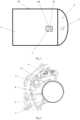
- Fig. 1 Part of a drive system comprised in a vehicle according to the present disclosure is shown in Fig. 1 .
- the drive system may comprise a housing 1, a cover 2 and a boost connector 3.
- Fig.1 merely shows the drive system in highly schematic form, in which the shapes and sizes, etc. of the various parts are not representative of the actual situation.
- an electric motor 4 of the drive system is arranged inside the substantially cylindrical housing 1, and has an electrical connector 7.
- the electrical connector 7 takes the form of a bus-bar, located at a drive side of the electric motor 4.
- the cover 2 is fixed to the housing 1; specifically, the cover is fixed to the housing 1 at a drive end of the electric motor.
- Fig. 1 the cover 2 is fixed to the housing 1; specifically, the cover is fixed to the housing 1 at a drive end of the electric motor.
- the cover 2 is formed with a cavity 6 accommodating a transmission 5 of the drive system.
- the boost connector 3 passes through the cover 2 and extends into the housing 1, and is electrically connected to the electrical connector 7 of the electric motor 4.
- the boost connector 3 is electrically connected to a winding of the electric motor via the electrical connector 7, and then electrically connected to an inverter, a high-voltage power distribution unit (PDU) and an on-board charger (OBC), etc. of the drive system.
- the boost connector 3 can boost power from a 400 V charging device to 800 V, to charge a battery of the vehicle.
- the boost connector of the present disclosure is installed at the drive end of the electric motor, closer to the electrical connector of the electric motor, thus making the structure more compact.
- the drive system further comprises a positioning shaft 8 for positioning a pawl 10 of a parking lock mechanism of the transmission 5, the positioning shaft 8 being fixed to a drive end wall 9 of the housing 1, and the pawl 10 being rotatable around the positioning shaft 8.
- the positioning shaft 8 is hollow and extends through the drive end wall 9 of the housing 1.
- the boost connector 3 extends from one end of the hollow positioning shaft through the positioning shaft into the housing.
- the present disclosure can use an existing structure to install the boost connector, so saves space and simplifies installation; moreover, the hollow shaft can be used to provide protection for the boost connector, thus improving reliability.
- this type of installation has little impact on the layout of the existing structure; in particular, it has no impact at all on the layout of the parking lock mechanism of the transmission.
- the installation of boost connectors of different sizes can be achieved by choosing the inner diameter of the hollow positioning shaft. For example, there is an option to suitably increase the inner diameter of the hollow positioning shaft to ensure that the boost connector passes through.
- the boost connector 3 comprises a connection seat 11 and a cable 12 fixed to the connection seat 11; the connection seat 11 is fixed to the cover 2 by a first fastener 13, and the cable 12 extends through the connection seat 11.
- the cable 12 may pass through a hole in the connection seat 11 and be fixed in the hole.
- the boost connector can be fixed to a transmission cover (i.e. the cover 2 in the present disclosure), and a certain degree of protection can be provided for the cable.
- the cover 2 is provided with an installation hole, the connection seat 11 being fixed in the installation hole, and a first sealing member 14 is arranged between the connection seat 11 and a hole wall of the installation hole.
- the first sealing member 14 comprises multiple sealing rings distributed in an extension direction of the cable 12.
- the first sealing member may be made of rubber or silicone rubber. In this way, a good sealing effect can be achieved, and the extension of the boost connector through the cover and the housing from the electric motor drive side will not affect the sealing of the drive system.
- connection seat 11 may comprise a flange 15, the first fastener 13 passing through the flange 15 and being fixed to the cover 2.
- the first fastener 13 may be a bolt, a screw, etc.
- a first end 16 of the cable 12 may be electrically connected to a power source, such as an external charging station. As shown in Figs. 1 and 3 , a second end 17 of the cable 12 extends into the housing 1 and is electrically connected to the electrical connector 7 of the electric motor 4 via a wiring terminal 18.
- an installation window 20 is provided on a peripheral side wall 19 of the housing 1; through the installation window 20, a second fastener 21 is used to fix the wiring terminal 18 to the electrical connector 7.
- the second fastener 21 may be a bolt, a screw, etc.
- the drive system further comprises an installation cover for closing the installation window 20, but this is not shown in the figures.
- the drive system further comprises a second sealing member which is not shown in the figures, the second sealing member being arranged between the installation cover and the installation window 20; the housing 1 is thus sealed by the second sealing member and the installation cover together.
- the second sealing member may be made of rubber or silicone rubber.
- the boost connector of the drive system described above is arranged at the drive end of the electric motor, extends through the transmission cover and the electric motor housing and is installed using the pawl positioning shaft of the parking lock mechanism; such a drive system is structurally compact, convenient to install, well-sealed and highly reliable.
- a vehicle of the present disclosure comprises the drive system described above.
- the vehicle may be an electrified vehicle, for example, a battery electric vehicle (BEV), a hybrid electric vehicle (HEV), a plug-in hybrid electric vehicle (PHEV), a range-extended EV, or a fuel cell electric vehicle (FCEV).
- BEV battery electric vehicle
- HEV hybrid electric vehicle
- PHEV plug-in hybrid electric vehicle
- FCEV fuel cell electric vehicle
- the vehicle may also be a hydrogen-powered vehicle. It should be understood that the vehicle of the present disclosure also has the advantages described above in relation to the drive system.
Landscapes
- Engineering & Computer Science (AREA)
- Mechanical Engineering (AREA)
- General Engineering & Computer Science (AREA)
- Power Engineering (AREA)
- Transportation (AREA)
- Chemical & Material Sciences (AREA)
- Combustion & Propulsion (AREA)
- Microelectronics & Electronic Packaging (AREA)
- Electric Propulsion And Braking For Vehicles (AREA)
- Motor Or Generator Frames (AREA)
Abstract
The present disclosure provides a drive system for a vehicle, and a vehicle. The drive system comprises: a housing, containing an electric motor of the drive system; a cover, fixed to the housing and formed with a cavity accommodating a transmission of the drive system; and a boost connector, passing through the cover and extending into the housing, and electrically connected to an electrical connector of the electric motor.
Description
- The present disclosure relates to a drive system for a vehicle, and a vehicle.
- Developments in science and technology coupled with technical progress have resulted in changes in automotive products with each passing day, and this has placed higher requirements on circuit connector products. In a new energy vehicle, a boost connector may be installed on an electric drive system, being used to electrically connect an external power source and an all-in-one product or electric motor of the electric drive system, for example to achieve boost charging of a battery. In a high-voltage, high-current environment, well-sealed and reliable power distribution and conduction are critical to the safety of the new energy vehicle as a whole. In an existing technical solution, a boost connector is generally installed at the non-drive end of the electric motor, in a position which is quite remote from an electrical connector of the electric motor; a larger space is needed to provide a protective component, resulting in an increase in the volume of the electric drive system. If installed at the drive end of the electric motor, the boost connector will need to pass through the transmission for connection to the electrical connector of the electric motor, and the position of the electrical connector and the parking lock mechanism in the transmission will make it difficult to find a suitable position to install the boost connector.
- Thus, there is a need for an electric drive system capable of solving the above-mentioned problems.
- Thus, an objective of the present disclosure is to provide a drive system for a vehicle, and a vehicle, wherein a boost connector of the drive system is arranged at a drive end of an electric motor, being structurally compact, convenient to install, well-sealed and highly reliable.
- The abovementioned objective is achieved through a drive system for a vehicle, and a vehicle, which are described below.
- The present disclosure provides a drive system for a vehicle, the drive system comprising: a housing, containing an electric motor of the drive system; a cover, fixed to the housing and formed with a cavity accommodating a transmission of the drive system; and a boost connector, passing through the cover and extending into the housing, and electrically connected to an electrical connector of the electric motor.
- Thus, the boost connector of the present disclosure is installed at the drive end of the electric motor, closer to the electrical connector of the electric motor, thus making the structure more compact.
- The drive system according to the present disclosure may also have one or more of the following features, individually or in combination.
- In one embodiment, the drive system further comprises a positioning shaft for positioning a pawl of a parking lock mechanism of the transmission, the positioning shaft being hollow and extending through a drive end wall of the housing, wherein the boost connector extends from one end of the hollow positioning shaft through the positioning shaft into the housing.
- In this way, the present disclosure can use an existing structure to install the boost connector, so saves space and simplifies installation; moreover, the hollow shaft can be used to provide protection for the boost connector, thus improving reliability. In addition, this type of installation has little impact on the layout of the existing structure; in particular, it has no impact at all on the layout of the parking lock mechanism of the transmission.
- In an embodiment, the boost connector comprises a connection seat and a cable fixed to the connection seat, the connection seat being fixed to the cover by a first fastener, and the cable extending through the connection seat.
- By means of the connection seat, the boost connector can be fixed to the transmission cover, and a certain degree of protection can be provided for the cable.
- In an embodiment, the cover is provided with an installation hole, the connection seat being fixed in the installation hole, and a first sealing member is arranged between the connection seat and a hole wall of the installation hole.
- In an embodiment, the first sealing member comprises multiple sealing rings distributed in an extension direction of the cable.
- In this way, a good sealing effect can be achieved, and the extension of the boost connector through the cover and the housing from the electric motor drive side will not affect the sealing of the drive system.
- In an embodiment, the connection seat comprises a flange, the first fastener passing through the flange and being fixed to the cover.
- In an embodiment, a first end of the cable is electrically connected to a power source, and a second end extends into the housing and is electrically connected to the electrical connector of the electric motor via a wiring terminal.
- In an embodiment, an installation window is provided on a peripheral side wall of the housing, and a second fastener is used to fix the wiring terminal to the electrical connector through the installation window.
- In an embodiment, the drive system further comprises an installation cover for closing the installation window.
- In an embodiment, the drive system further comprises a second sealing member, arranged between the installation cover and the installation window.
- The present disclosure further provides a vehicle, comprising the drive system described above.
- A better understanding of the advantages and objective of the present disclosure can be gained from the preferred embodiments of the present disclosure described in detail below with reference to the drawings. To better illustrate the relationships among components in the drawings, the drawings are not drawn to scale. In the drawings:
-
Fig. 1 shows a highly schematic drawing of a drive system for a vehicle according to an embodiment of the present disclosure; -
Fig. 2 shows a schematic drawing of an end of a drive system according to an embodiment of the present disclosure; and -
Fig. 3 shows a sectional schematic drawing of part of a drive system according to an embodiment of the present disclosure. - In order to clarify the technical solution and its objective and advantages of the present disclosure, the technical solutions of embodiments of the present disclosure are described clearly and completely below in conjunction with the drawings of particular embodiments of the present disclosure. In the drawings, identical reference numerals denote identical components. It must be explained that the embodiments described are some, not all, of the embodiments of the present disclosure. All other embodiments obtained by those skilled in the art based on the described embodiments of the present disclosure without the need for inventive effort shall fall within the scope of protection of the present disclosure.
- Unless otherwise defined, the technical or scientific terms used herein shall have the common meanings understood by those skilled in the art. The words "first", "second", and the like used in the description and claims of the patent application disclosed herein do not indicate any order, quantity or importance, being merely used to distinguish different component parts. Likewise, words such as "a" or "one" do not necessarily represent a quantity limit. Words such as "comprising", "including" or "having" mean that the element or object preceding the word covers the elements or objects and equivalents thereof listed after the word, without excluding other elements or objects. Words such as "connection" or "communication", rather than being limited to the physical or mechanical connection or communication shown in a drawing, may include connection or communication equivalent thereto, irrespective of whether it is direct or indirect. "Upper", "lower", "left", "right", etc. are only used to indicate a relative positional relationship, and when the absolute position of a described object changes, the relative positional relationship may also change accordingly.
- A drive system of a vehicle generally comprises an electric motor, a speed reducer and a power electronics unit. The electric motor converts inputted electrical energy to rotational mechanical energy; the speed reducer is mechanically coupled to the electric motor, adjusts the speed of rotation and the torque generated by the electric motor, and then transmits same to wheels of the vehicle. The power electronics unit may comprise at least one of an inverter, an on-board charger and a DC-DC converter. The inverter can be used to invert DC outputted by an electrical energy storage means (e.g. a battery or another electrical energy storage means) to AC capable of driving the electric motor; the on-board charger can charge the electrical energy storage means when the vehicle is recovering energy; and the DC-DC converter can convert high-voltage DC outputted by the electrical energy storage means to low-voltage DC suitable for use in a low-voltage system of the vehicle. The electric motor and the speed reducer in the drive system are generally arranged adjacent to each other, to facilitate mechanical coupling therebetween.
- Various embodiments of the present disclosure will be described in detail below with reference to
Figs. 1 to 3 . - Part of a drive system comprised in a vehicle according to the present disclosure is shown in
Fig. 1 . The drive system may comprise ahousing 1, acover 2 and aboost connector 3.Fig.1 merely shows the drive system in highly schematic form, in which the shapes and sizes, etc. of the various parts are not representative of the actual situation. In addition, as shown inFig. 2 , anelectric motor 4 of the drive system is arranged inside the substantiallycylindrical housing 1, and has anelectrical connector 7. For example, theelectrical connector 7 takes the form of a bus-bar, located at a drive side of theelectric motor 4. As shown inFig. 1 , thecover 2 is fixed to thehousing 1; specifically, the cover is fixed to thehousing 1 at a drive end of the electric motor. As shown inFig. 2 , thecover 2 is formed with acavity 6 accommodating atransmission 5 of the drive system. Theboost connector 3 passes through thecover 2 and extends into thehousing 1, and is electrically connected to theelectrical connector 7 of theelectric motor 4. For example, theboost connector 3 is electrically connected to a winding of the electric motor via theelectrical connector 7, and then electrically connected to an inverter, a high-voltage power distribution unit (PDU) and an on-board charger (OBC), etc. of the drive system. For example, theboost connector 3 can boost power from a 400 V charging device to 800 V, to charge a battery of the vehicle. - Thus, the boost connector of the present disclosure is installed at the drive end of the electric motor, closer to the electrical connector of the electric motor, thus making the structure more compact.
- As shown in
Fig. 2 , the drive system further comprises apositioning shaft 8 for positioning apawl 10 of a parking lock mechanism of thetransmission 5, thepositioning shaft 8 being fixed to adrive end wall 9 of thehousing 1, and thepawl 10 being rotatable around thepositioning shaft 8. Thepositioning shaft 8 is hollow and extends through thedrive end wall 9 of thehousing 1. Theboost connector 3 extends from one end of the hollow positioning shaft through the positioning shaft into the housing. - In this way, the present disclosure can use an existing structure to install the boost connector, so saves space and simplifies installation; moreover, the hollow shaft can be used to provide protection for the boost connector, thus improving reliability. In addition, this type of installation has little impact on the layout of the existing structure; in particular, it has no impact at all on the layout of the parking lock mechanism of the transmission.
- Specifically, the installation of boost connectors of different sizes can be achieved by choosing the inner diameter of the hollow positioning shaft. For example, there is an option to suitably increase the inner diameter of the hollow positioning shaft to ensure that the boost connector passes through.
- As shown in
Fig. 3 , theboost connector 3 comprises aconnection seat 11 and acable 12 fixed to theconnection seat 11; theconnection seat 11 is fixed to thecover 2 by afirst fastener 13, and thecable 12 extends through theconnection seat 11. Thecable 12 may pass through a hole in theconnection seat 11 and be fixed in the hole. By means of theconnection seat 11, the boost connector can be fixed to a transmission cover (i.e. thecover 2 in the present disclosure), and a certain degree of protection can be provided for the cable. - As shown in
Fig. 3 , thecover 2 is provided with an installation hole, theconnection seat 11 being fixed in the installation hole, and a first sealingmember 14 is arranged between theconnection seat 11 and a hole wall of the installation hole. Thefirst sealing member 14 comprises multiple sealing rings distributed in an extension direction of thecable 12. The first sealing member may be made of rubber or silicone rubber. In this way, a good sealing effect can be achieved, and the extension of the boost connector through the cover and the housing from the electric motor drive side will not affect the sealing of the drive system. - As shown in
Fig. 3 , theconnection seat 11 may comprise aflange 15, thefirst fastener 13 passing through theflange 15 and being fixed to thecover 2. For example, thefirst fastener 13 may be a bolt, a screw, etc. - A
first end 16 of thecable 12 may be electrically connected to a power source, such as an external charging station. As shown inFigs. 1 and3 , asecond end 17 of thecable 12 extends into thehousing 1 and is electrically connected to theelectrical connector 7 of theelectric motor 4 via awiring terminal 18. - Again referring to
Fig. 1 , aninstallation window 20 is provided on aperipheral side wall 19 of thehousing 1; through theinstallation window 20, asecond fastener 21 is used to fix thewiring terminal 18 to theelectrical connector 7. For example, thesecond fastener 21 may be a bolt, a screw, etc. - To facilitate installation, the drive system further comprises an installation cover for closing the
installation window 20, but this is not shown in the figures. The drive system further comprises a second sealing member which is not shown in the figures, the second sealing member being arranged between the installation cover and theinstallation window 20; thehousing 1 is thus sealed by the second sealing member and the installation cover together. The second sealing member may be made of rubber or silicone rubber. - The boost connector of the drive system described above is arranged at the drive end of the electric motor, extends through the transmission cover and the electric motor housing and is installed using the pawl positioning shaft of the parking lock mechanism; such a drive system is structurally compact, convenient to install, well-sealed and highly reliable.
- A vehicle of the present disclosure comprises the drive system described above. The vehicle may be an electrified vehicle, for example, a battery electric vehicle (BEV), a hybrid electric vehicle (HEV), a plug-in hybrid electric vehicle (PHEV), a range-extended EV, or a fuel cell electric vehicle (FCEV). The vehicle may also be a hydrogen-powered vehicle. It should be understood that the vehicle of the present disclosure also has the advantages described above in relation to the drive system.
- In addition, the technical features disclosed above are not limited to combinations of the disclosed features with other features, and those skilled in the art could combine technical features in other ways according to the objective of the invention, to realize the objective of the present disclosure.
Claims (11)
- A drive system for a vehicle, characterized in that the drive system comprises:a housing (1), in which an electric motor (4) of the drive system is provided;a cover (2), which is attached to the housing (1) and forms a cavity (6) accommodating a transmission (5) of the drive system; anda boost connector (3), which extends through the cover (2) and into an interior of the housing, and is electrically connected to an electrical connector (7) of the electric motor (4).
- The drive system according to claim 1, characterized in that
the drive system further comprises a positioning shaft (8) for positioning a pawl (10) of a parking lock mechanism of a transmission (5), the positioning shaft (8) being hollow and extending through a drive end wall (9) of the housing (1), wherein the boost connector (3) extends from one end of the positioning shaft through the positioning shaft to the interior of the housing (1). - The drive system according to claim 1 or 2, characterized in that
the boost connector (3) comprises a connection seat (11) and a cable (12) fixed to the connection seat, the connection seat being fixed to the cover (2) by a first fastener (13), and the cable (12) extending through the connection seat. - The drive system according to claim 3, characterized in that
an installation hole is provided on the cover (2), the connection seat (11) is fixed in the installation hole, and a first sealing member (14) is provided between the connection seat (11) and a hole wall of the installation hole. - The drive system according to claim 4, characterized in that
the first sealing member (14) comprises a plurality of sealing rings distributed along an extension direction of the cable. - The drive system according to one of the claims 3 to 5, characterized in that the connection seat (11) comprises a flange (15) through which the first fastener (13) is fixed to the cover (2).
- The drive system according to one of the claims 3 to 6, characterized in that
a first end (16) of the cable (12) is electrically connected to a power source, and a second end (17) extends into the housing and is electrically connected to the electrical connector (7) of the electric motor (4) via a wiring terminal (18). - The drive system according to claim 7, characterized in that
an installation window (20) is provided on a peripheral side wall (19) of the housing (1), and a second fastener (21) is used to fix the wiring terminal (18) to the electrical connector (7) through the installation window. - The drive system according to claim 8, characterized in that
the drive system further comprises an installation cover for closing the installation window (20). - The drive system according to claim 9, characterized in that
the drive system further comprises a second sealing member which is provided between the installation cover and the installation window. - A vehicle, characterized in that the vehicle comprises the drive system according to any one of claims 1 to 10.
Applications Claiming Priority (1)
| Application Number | Priority Date | Filing Date | Title |
|---|---|---|---|
| CN202311679526.2A CN120127911A (en) | 2023-12-07 | 2023-12-07 | Drive system for vehicle and vehicle |
Publications (1)
| Publication Number | Publication Date |
|---|---|
| EP4568077A1 true EP4568077A1 (en) | 2025-06-11 |
Family
ID=93843361
Family Applications (1)
| Application Number | Title | Priority Date | Filing Date |
|---|---|---|---|
| EP24218446.3A Pending EP4568077A1 (en) | 2023-12-07 | 2024-12-09 | Drive system for vehicle, and vehicle |
Country Status (4)
| Country | Link |
|---|---|
| US (1) | US12545090B2 (en) |
| EP (1) | EP4568077A1 (en) |
| KR (1) | KR20250087475A (en) |
| CN (1) | CN120127911A (en) |
Citations (4)
| Publication number | Priority date | Publication date | Assignee | Title |
|---|---|---|---|---|
| US20140374139A1 (en) * | 2013-06-25 | 2014-12-25 | Yazaki Corporation | Booster cable holding structure |
| US20170237312A1 (en) * | 2016-01-15 | 2017-08-17 | Cts Corporation | Actuator |
| US20230001793A1 (en) * | 2019-11-29 | 2023-01-05 | Valeo Siemens Eautomotive Germany Gmbh | Transmission device for an electrically driveable vehicle, drive device for an electrically driveable vehicle, and vehicle |
| WO2023061800A1 (en) * | 2021-10-12 | 2023-04-20 | Valeo Systemes De Controle Moteur | Actuator for a parking lock system of a vehicle gearbox |
Family Cites Families (14)
| Publication number | Priority date | Publication date | Assignee | Title |
|---|---|---|---|---|
| JP4926019B2 (en) * | 2007-12-07 | 2012-05-09 | 本田技研工業株式会社 | Connection structure for vehicle cables |
| US8052427B2 (en) * | 2009-04-01 | 2011-11-08 | GM Global Technology Operations LLC | Connector assembly for coupling an electric motor to a power source |
| US8523576B2 (en) * | 2011-10-24 | 2013-09-03 | GM Global Technology Operations LLC | Connector for coupling an electric motor to a power source |
| JP2013115904A (en) * | 2011-11-28 | 2013-06-10 | Hitachi Automotive Systems Ltd | Combined mechano-electric electric driving apparatus |
| DE102012200488A1 (en) | 2012-01-13 | 2013-03-28 | Schaeffler Technologies AG & Co. KG | Drive train for electric drive of axle of e.g. motor vehicle, has one side open main portion connected with lead terminals and cover that is provided for closing connecting box |
| KR102182647B1 (en) | 2013-11-08 | 2020-11-24 | 주식회사 브이씨텍 | Integrated electric drive system for electric vehicle |
| CN105827060A (en) | 2015-01-08 | 2016-08-03 | 大陆汽车投资(上海)有限公司 | integrated electric drive system |
| DE102016014523A1 (en) * | 2016-12-07 | 2018-06-07 | Fte Automotive Gmbh | Electric parking brake actuator for actuating a parking brake in a motor vehicle |
| DE102019132496A1 (en) * | 2019-11-29 | 2021-06-02 | Valeo Siemens Eautomotive Germany Gmbh | Transmission device for an electrically drivable vehicle, drive device for an electrically drivable vehicle and vehicle |
| CN114094746B (en) | 2020-06-29 | 2024-02-27 | 比亚迪股份有限公司 | Motor, power assembly and vehicle |
| CN112555407B (en) | 2020-12-29 | 2022-06-10 | 南京朗禾智能控制研究院有限公司 | Vehicle parking mechanism |
| DE102021130767B4 (en) | 2021-11-24 | 2025-03-27 | Schaeffler Technologies AG & Co. KG | Electric drivetrain with electrical interface and electric vehicle with such an electric drivetrain |
| CN115570995A (en) | 2022-09-22 | 2023-01-06 | 广汽埃安新能源汽车有限公司 | A pure electric vehicle boost system and pure electric vehicle |
| CN116461445A (en) | 2023-03-29 | 2023-07-21 | 中国第一汽车股份有限公司 | Boosting system, method and vehicle |
-
2023
- 2023-12-07 CN CN202311679526.2A patent/CN120127911A/en active Pending
-
2024
- 2024-12-05 KR KR1020240179177A patent/KR20250087475A/en active Pending
- 2024-12-06 US US18/971,095 patent/US12545090B2/en active Active
- 2024-12-09 EP EP24218446.3A patent/EP4568077A1/en active Pending
Patent Citations (4)
| Publication number | Priority date | Publication date | Assignee | Title |
|---|---|---|---|---|
| US20140374139A1 (en) * | 2013-06-25 | 2014-12-25 | Yazaki Corporation | Booster cable holding structure |
| US20170237312A1 (en) * | 2016-01-15 | 2017-08-17 | Cts Corporation | Actuator |
| US20230001793A1 (en) * | 2019-11-29 | 2023-01-05 | Valeo Siemens Eautomotive Germany Gmbh | Transmission device for an electrically driveable vehicle, drive device for an electrically driveable vehicle, and vehicle |
| WO2023061800A1 (en) * | 2021-10-12 | 2023-04-20 | Valeo Systemes De Controle Moteur | Actuator for a parking lock system of a vehicle gearbox |
Also Published As
| Publication number | Publication date |
|---|---|
| US12545090B2 (en) | 2026-02-10 |
| US20250187415A1 (en) | 2025-06-12 |
| CN120127911A (en) | 2025-06-10 |
| KR20250087475A (en) | 2025-06-16 |
Similar Documents
| Publication | Publication Date | Title |
|---|---|---|
| US10661668B2 (en) | Power conversion apparatus and junction box | |
| US8466586B2 (en) | High-voltage terminal assembly with integral high-voltage interlock | |
| JP3112226B2 (en) | Charging connector for electric vehicles | |
| US7786386B2 (en) | High-voltage vehicle component connection method and apparatus | |
| US8993890B2 (en) | Electric cable and electric connector | |
| JP2011216424A (en) | Power storage module | |
| US11548379B2 (en) | Electrified vehicle including remote terminals accessible via charging port door | |
| US8523576B2 (en) | Connector for coupling an electric motor to a power source | |
| KR102182647B1 (en) | Integrated electric drive system for electric vehicle | |
| CN109228868A (en) | High voltage distribution box and electric car | |
| US12187203B2 (en) | Wiring module and power distribution apparatus having the same | |
| US12545090B2 (en) | Drive system for vehicle, and vehicle | |
| US11990306B2 (en) | Electrified vehicle traction powertrain module having removably insertable fuse box | |
| US11664624B2 (en) | Electrical connectors with disconnection blocking features | |
| US11688985B2 (en) | Electrical interconnect system for an electric vehicle | |
| US20240051479A1 (en) | Electrified Vehicle Traction Powertrain Module Having Externally Integrated Fuse Box | |
| CN212579643U (en) | Low-power non-vehicle-mounted charger with high protection performance | |
| WO2021161787A1 (en) | Battery connection system | |
| CN222601389U (en) | Vehicle controller and vehicle | |
| CN222875776U (en) | Wireless charging device for electric vehicle | |
| US20260014882A1 (en) | Power Line Assembly and Motor Vehicle | |
| US12603544B2 (en) | Connection structure | |
| CN218513632U (en) | Battery pack system and vehicle including the same | |
| WO2018054453A1 (en) | An electrical junction box | |
| CN118630416A (en) | Battery pack and vehicle |
Legal Events
| Date | Code | Title | Description |
|---|---|---|---|
| PUAI | Public reference made under article 153(3) epc to a published international application that has entered the european phase |
Free format text: ORIGINAL CODE: 0009012 |
|
| STAA | Information on the status of an ep patent application or granted ep patent |
Free format text: STATUS: REQUEST FOR EXAMINATION WAS MADE |
|
| STAA | Information on the status of an ep patent application or granted ep patent |
Free format text: STATUS: EXAMINATION IS IN PROGRESS |
|
| 17P | Request for examination filed |
Effective date: 20241209 |
|
| AK | Designated contracting states |
Kind code of ref document: A1 Designated state(s): AL AT BE BG CH CY CZ DE DK EE ES FI FR GB GR HR HU IE IS IT LI LT LU LV MC ME MK MT NL NO PL PT RO RS SE SI SK SM TR |
|
| 17Q | First examination report despatched |
Effective date: 20250516 |