EP4568067A1 - Embedded magnet-type rotor and rotary electric machine - Google Patents
Embedded magnet-type rotor and rotary electric machine Download PDFInfo
- Publication number
- EP4568067A1 EP4568067A1 EP23850004.5A EP23850004A EP4568067A1 EP 4568067 A1 EP4568067 A1 EP 4568067A1 EP 23850004 A EP23850004 A EP 23850004A EP 4568067 A1 EP4568067 A1 EP 4568067A1
- Authority
- EP
- European Patent Office
- Prior art keywords
- flux barrier
- base portion
- rotor
- iron core
- magnetic pole
- Prior art date
- Legal status (The legal status is an assumption and is not a legal conclusion. Google has not performed a legal analysis and makes no representation as to the accuracy of the status listed.)
- Pending
Links
Images



Classifications
-
- H—ELECTRICITY
- H02—GENERATION; CONVERSION OR DISTRIBUTION OF ELECTRIC POWER
- H02K—DYNAMO-ELECTRIC MACHINES
- H02K1/00—Details of the magnetic circuit
- H02K1/06—Details of the magnetic circuit characterised by the shape, form or construction
- H02K1/22—Rotating parts of the magnetic circuit
- H02K1/27—Rotor cores with permanent magnets
- H02K1/2706—Inner rotors
- H02K1/272—Inner rotors the magnetisation axis of the magnets being perpendicular to the rotor axis
- H02K1/274—Inner rotors the magnetisation axis of the magnets being perpendicular to the rotor axis the rotor consisting of two or more circumferentially positioned magnets
- H02K1/2753—Inner rotors the magnetisation axis of the magnets being perpendicular to the rotor axis the rotor consisting of two or more circumferentially positioned magnets the rotor consisting of magnets or groups of magnets arranged with alternating polarity
- H02K1/276—Magnets embedded in the magnetic core, e.g. interior permanent magnets [IPM]
- H02K1/2766—Magnets embedded in the magnetic core, e.g. interior permanent magnets [IPM] having a flux concentration effect
-
- H—ELECTRICITY
- H02—GENERATION; CONVERSION OR DISTRIBUTION OF ELECTRIC POWER
- H02K—DYNAMO-ELECTRIC MACHINES
- H02K2213/00—Specific aspects, not otherwise provided for and not covered by codes H02K2201/00 - H02K2211/00
- H02K2213/03—Machines characterised by numerical values, ranges, mathematical expressions or similar information
Definitions
- the present invention relates to an embedded magnet rotor and a rotary electric machine.
- Patent Literature 1 proposes a rotor having a flux barrier having a shape extending inward from a magnet end portion toward a magnetic pole center in order to reduce a torque ripple of a rotary electric machine.
- Patent Literature 1 JP 5696820 B2
- the present invention has been made in view of the above circumstances, and provides an embedded magnet rotor capable of suppressing demagnetization at a magnet end portion away from a magnetic pole center while maintaining a reduction effect of an electromagnetic excitation force.
- One aspect of the present invention is an embedded magnet rotor in which a plurality of magnetic poles are formed in a circumferential direction of an iron core.
- Each magnetic pole includes the iron core in which a magnet is arranged, and has a first flux barrier and a second flux barrier at end portions of the magnet, respectively, across a magnetic pole center.
- the first flux barrier includes a first base portion formed radially outward from a first end portion of the magnet, and a first extending portion communicating with the first base portion and extending circumferentially from the first base portion toward the magnetic pole center.
- the second flux barrier includes a second base portion formed radially outward from a second end portion of the magnet, and a second extending portion arranged away from the second base portion with the iron core in between and extending in a circumferential direction from the second base portion side toward the magnetic pole center. Between the second base portion and the second extending portion, a magnetic flux bypass portion connecting an outer periphery and an inner periphery of a rotor in a radial direction by the iron core is formed.
- a width of the magnetic flux bypass portion may be smaller than a radial width from an outer periphery of the iron core to the second flux barrier.
- a rotary electric machine includes a stator and the embedded magnet rotor described above.
- the rotary electric machine described above may be a motor, and, in each magnetic pole, the second flux barrier and the magnetic flux bypass portion may be arranged on a forward rotation side, and the first flux barrier is arranged on a reverse rotation side.
- the rotary electric machine described above may be an electric generator, and, in each magnetic pole, the first flux barrier may be arranged on a forward rotation side, and the second flux barrier and the magnetic flux bypass portion may be arranged on a reverse rotation side.
- an embedded magnet rotor capable of suppressing demagnetization at a magnet end portion away from a magnetic pole center while maintaining a reduction effect of an electromagnetic excitation force.
- Fig. 1 is a cross-sectional view illustrating a transverse cross section in a direction orthogonal to a rotation axis Ax in a rotary electric machine of the present embodiment.
- a direction parallel to an extending direction of the rotation axis Ax is referred to as an axial direction
- a circumferential direction around the rotation axis Ax is simply referred to as a circumferential direction
- a radial direction around the rotation axis Ax is simply referred to as a radial direction.
- a rotary electric machine 1 illustrated in Fig. 1 is an inner rotor type motor, and includes a rotor 2 which is an example of an embedded magnet rotor, and a cylindrical stator 3 arranged on an outer periphery of the rotor 2.
- the extending direction (axial direction) of the rotation axis Ax of the rotary electric machine 1 is a direction perpendicular to the page. Note that, in the rotary electric machine 1 in Fig. 1 , a clockwise direction is defined as a forward rotation direction.
- the stator 3 is arranged on the outer periphery of the rotor 2 with an air gap in between.
- the rotor 2 rotates about the rotation axis Ax with an attractive force or a repulsive force with respect to the magnetic field of the rotor 2.
- the stator 3 accommodates the rotor 2 in a central space portion around the rotation axis Ax.
- a plurality of teeth 3a each protruding radially inward toward the rotation axis Ax are provided side by side at equal intervals in the circumferential direction. Between the adjacent teeth 3a, slots are individually formed.
- the coil 3b is attached to the slot of the stator 3 along the outer periphery of the rotor 2.
- the rotor 2 includes an iron core 4, a shaft 5, and a permanent magnet 6.
- the iron core 4 of the rotor 2 is, for example, a cylindrical member formed by stacking punched silicon steel sheets in the axial direction. An insulating adhesive is interposed between the individual silicon steel sheets constituting the iron core 4, and the individual silicon steel sheets are insulated from each other.
- the shaft 5 is fitted in a shaft center portion of the iron core 4 along the rotation axis Ax. In the rotary electric machine 1, the shaft 5 is rotatably supported by a bearing (not illustrated).
- the rotor 2 of the present embodiment is an eight-pole rotor, and the permanent magnets 6 are arranged in a predetermined arrangement in the iron core 4 of the rotor 2 so that eight magnetic poles are formed at equal intervals along the circumferential direction.
- the permanent magnets 6 are arranged such that magnetic poles adjacent to each other in the circumferential direction in the rotor 2 have polarities opposite to each other.
- a pair of permanent magnets 6 is arranged per magnetic pole in a tapered pattern in which a distance between the permanent magnets 6 increases toward the outer periphery of the iron core 4.
- Each permanent magnet 6 has a rectangular cross-sectional shape intersecting with the axial direction, and is magnetized in a direction orthogonal to a long side on a plane orthogonal to the rotation axis Ax.
- magnetic pole surfaces facing the outer peripheral side are all aligned to the same magnetic polarity (S pole or N pole).
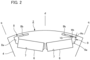
- Fig. 2 is a diagram illustrating the rotor 2 for one magnetic pole in the present embodiment.
- an axis connecting an axial center (rotation axis Ax) of the rotor 2 in Fig. 1 and a magnetic pole center for generating magnet torque is a d-axis of d-q axis coordinates.
- an axis orthogonal to the d-axis in terms of an electrical angle is a q-axis of the d-q axis coordinate.
- a portion between a pair of q axes adjacent to each other serves as an auxiliary magnetic pole portion that generates a reactant torque.
- two magnet holes 7 for fitting magnets are formed to penetrate the iron core 4 in the axial direction.
- the magnet holes 7 are formed in a tapered pattern in which a distance between the magnet holes 7 increases toward the outer periphery of the iron core 4 so as to be line-symmetric with respect to the magnetic pole center.
- first flux barrier 8 and a second flux barrier 9 are individually formed on the outer peripheral side from the permanent magnet 6 of the iron core 4.
- the first flux barrier 8 and the second flux barrier 9 are substantially line-symmetric with respect to the d-axis, and are both formed so as to penetrate the iron core 4 in the axial direction.
- the first flux barrier 8 is arranged on the reverse rotation side (left side in the drawing) with respect to the d-axis
- the second flux barrier 9 is arranged on the forward rotation side (right side in the drawing) with respect to the d-axis.
- the first flux barrier 8 has a first base portion 8a and a first extending portion 8b.
- the first base portion 8a of the first flux barrier 8 communicates with the magnet hole 7 on the reverse rotation side, and extends radially outward from an end portion of the permanent magnet 6. Further, the first extending portion 8b of the first flux barrier 8 communicates with the first base portion 8a, and extends circumferentially inward from the first base portion 8a toward the d-axis side.
- the second flux barrier 9 has a second base portion 9a and a second extending portion 9b.
- the second base portion 9a of the second flux barrier 9 communicates with the magnet hole 7 on the forward rotation side, and extends radially outward from an end portion of the permanent magnet 6. Further, the second extending portion 9b of the second flux barrier 9 is formed between the first extending portion 8b and the second base portion 9a in the circumferential direction, and is separated from the second base portion 9a by the iron core (a magnetic flux bypass portion 10 described later).
- the second extending portion 9b extends inward in the circumferential direction from the second base portion 9a side toward the d-axis side, and a distal end of the second extending portion 9b faces a distal end of the first extending portion 8b across the d-axis.
- the first extending portion 8b and the second extending portion 9b are each formed with a width wa in the radial direction from the outer periphery of the rotor 2.
- the magnetic flux bypass portion 10 connecting an outer periphery and an inner periphery of the rotor 2 in the radial direction by the iron core 4 is formed.
- a width Wb (interval from the second base portion 9a to the second extending portion 9b) of the magnetic flux bypass portion 10 is preferably formed to be smaller than the radial width Wa of the iron core 4 from the outer periphery of the rotor 2 to the second flux barrier 9 (Wa > Wb).
- Each of the first flux barrier 8 and the second flux barrier 9 is a hole (space), has a magnetic permeability extremely smaller than that of the iron core 4, and is less likely to allow a magnetic flux to pass therethrough. Therefore, the first flux barrier 8 and the second flux barrier 9 function as a magnetic blocking portion. Note that, in a case where the hole (space) forming the first flux barrier 8 and the second flux barrier 9 is filled with a nonmagnetic metal having a low magnetic permeability (for example, aluminum, brass, or the like), an adhesive, a varnish, a resin, or the like, each of the holes functions as a magnetic blocking portion.
- a nonmagnetic metal having a low magnetic permeability for example, aluminum, brass, or the like
- the first flux barrier 8 and the second flux barrier 9 are formed between the d-axis and the q-axis of the rotor 2, so that harmonic components included in a waveform of a magnetic flux density are suppressed.
- distribution of a magnetic flux density generated on the outer peripheral surface of the rotor 2 by the permanent magnet 6 is changed, and in particular, magnetic flux density distribution at both circumferential end portions of the magnetic pole approaches a sine wave.
- an electromagnetic excitation force such as a torque ripple in the rotor 2 is effectively reduced.
- the magnetic flux bypass portion 10 is formed on the second flux barrier 9 side, demagnetization in the permanent magnet 6 is suppressed.
- demagnetization suppression effect in the magnetic flux bypass portion 10 will be described.
- Fig. 3(a) is a schematic diagram illustrating a flow of magnetic flux in a rotor 2' of a comparative example
- Fig. 3(b) is a schematic diagram illustrating a flow of a magnetic flux in the rotor 2 of the present embodiment.
- the comparative example illustrated in Fig. 3(a) is different from the present embodiment in that the magnetic flux bypass portion 10 is not formed in a second flux barrier 9', and the second base portion 9a and the second extending portion 9b communicate with each other.
- a flow of a magnetic flux is indicated by an arrow.
- a magnetic flux generated in the rotor 2' during forward rotation of the motor is directed from the stator side toward the permanent magnet 6 on the inner peripheral side. Thereafter, a part of the magnetic flux passes through the iron core on the outer peripheral side from the second extending portion 9b, and flows toward an adjacent magnetic pole.
- the magnetic flux passing through the inner peripheral side from the second extending portion 9b does not easily pass through the second extending portion 9b, the magnetic flux easily flows to the iron core through the permanent magnet 6. As a result, demagnetization in the permanent magnet 6 easily occurs in the comparative example.
- a part of a magnetic flux passing through the inner peripheral side from the second extending portion 9b passes through the iron core of the magnetic flux bypass portion 10, and flows from the outer peripheral side of the second base portion 9a toward an adjacent magnetic pole.
- a part of the magnetic flux passing through the inner peripheral side from the second extending portion 9b is bypassed to the outer peripheral side of the rotor in the vicinity of the end portion of the permanent magnet 6, and the magnetic flux flowing to the iron core through the permanent magnet 6 is reduced as compared with the comparative example. Therefore, demagnetization in the permanent magnet 6 is suppressed.
- a torque ripple can be effectively suppressed by making the width Wb of the magnetic flux bypass portion 10 smaller than the radial width Wa from the outer periphery of the rotor 2 to the second flux barrier 9.
- Fig. 4 is a graph illustrating a simulation result of a relationship between a ratio of Wb and Wa and a torque ripple.
- the embedded magnet rotor of the present invention may be applied to an electric generator.
- the configuration of the forward rotation direction and the reverse rotation direction is reversed, and the first flux barrier is arranged on the forward rotation side while the second flux barrier having the magnetic flux bypass portion is arranged on the reverse rotation side.
- the arrangement of the permanent magnets 6 is not limited to the above.
- one permanent magnet extending in a direction orthogonal to the d-axis may be arranged for one magnetic pole.
Landscapes
- Engineering & Computer Science (AREA)
- Power Engineering (AREA)
- Permanent Field Magnets Of Synchronous Machinery (AREA)
Abstract
Each magnetic pole of an embedded magnet rotor includes an iron core in which a magnet is arranged, and has a first flux barrier and a second flux barrier at end portions of the magnet, respectively, across a magnetic pole center. The first flux barrier includes a first extending portion communicating with a first base portion and extending circumferentially from the first base portion toward the magnetic pole center. The second flux barrier includes a second extending portion arranged away from a second base portion with the iron core in between and extending in a circumferential direction from the second base portion side toward the magnetic pole center. Between the second base portion and the second extending portion, a magnetic flux bypass portion connecting an outer periphery and an inner periphery of a rotor in a radial direction by the iron core is formed.
Description
- The present invention relates to an embedded magnet rotor and a rotary electric machine.
- In electric vehicles such as an EV, an HEV, and a PHEV, further reduction in vibration and noise is desired. In order to reduce vibration and noise, it is important to reduce an electromagnetic excitation force of a torque ripple or the like in a rotary electric machine.
- For example,
Patent Literature 1 proposes a rotor having a flux barrier having a shape extending inward from a magnet end portion toward a magnetic pole center in order to reduce a torque ripple of a rotary electric machine. - Patent Literature 1:
JP 5696820 B2 - In the rotor having the flux barrier in
Patent Literature 1, when a current flows through a coil of a stator, a magnetic flux is less likely to flow on an end portion side in a circumferential direction. Therefore, in the rotor ofPatent Literature 1, a magnetic flux flowing through the magnet to an iron core is likely to increase, and demagnetization is likely to occur particularly at a magnet end portion away from the magnetic pole center. - The present invention has been made in view of the above circumstances, and provides an embedded magnet rotor capable of suppressing demagnetization at a magnet end portion away from a magnetic pole center while maintaining a reduction effect of an electromagnetic excitation force.
- One aspect of the present invention is an embedded magnet rotor in which a plurality of magnetic poles are formed in a circumferential direction of an iron core. Each magnetic pole includes the iron core in which a magnet is arranged, and has a first flux barrier and a second flux barrier at end portions of the magnet, respectively, across a magnetic pole center. The first flux barrier includes a first base portion formed radially outward from a first end portion of the magnet, and a first extending portion communicating with the first base portion and extending circumferentially from the first base portion toward the magnetic pole center. The second flux barrier includes a second base portion formed radially outward from a second end portion of the magnet, and a second extending portion arranged away from the second base portion with the iron core in between and extending in a circumferential direction from the second base portion side toward the magnetic pole center. Between the second base portion and the second extending portion, a magnetic flux bypass portion connecting an outer periphery and an inner periphery of a rotor in a radial direction by the iron core is formed.
- A width of the magnetic flux bypass portion may be smaller than a radial width from an outer periphery of the iron core to the second flux barrier.
- A rotary electric machine according to another aspect of the present invention includes a stator and the embedded magnet rotor described above.
- The rotary electric machine described above may be a motor, and, in each magnetic pole, the second flux barrier and the magnetic flux bypass portion may be arranged on a forward rotation side, and the first flux barrier is arranged on a reverse rotation side.
- The rotary electric machine described above may be an electric generator, and, in each magnetic pole, the first flux barrier may be arranged on a forward rotation side, and the second flux barrier and the magnetic flux bypass portion may be arranged on a reverse rotation side.
- According to one aspect of the present invention, it is possible to provide an embedded magnet rotor capable of suppressing demagnetization at a magnet end portion away from a magnetic pole center while maintaining a reduction effect of an electromagnetic excitation force.
-
-
Fig. 1 is a transverse cross-sectional view of a rotary electric machine of the present embodiment. -
Fig. 2 is a diagram illustrating a rotor for one magnetic pole in the present embodiment. -
Fig. 3 is a schematic diagram illustrating a flow of a magnetic flux in a rotor of a comparative example and a rotor of the present embodiment. -
Fig. 4 is a graph illustrating a simulation result of a relationship between a ratio of Wb and Wa and a torque ripple. - Hereinafter, an embodiment of the present invention will be described with reference to the drawings.
- In the embodiment, for easy understanding, structures and elements other than a main part of the present invention will be described in a simplified or omitted manner. Further, in the drawings, the same elements are denoted by the same reference numerals. Note that, shapes, dimensions, and the like of individual elements illustrated in the drawings are schematically illustrated, and do not indicate actual shapes, dimensions, and the like.
-
Fig. 1 is a cross-sectional view illustrating a transverse cross section in a direction orthogonal to a rotation axis Ax in a rotary electric machine of the present embodiment. Note that, in the following description, a direction parallel to an extending direction of the rotation axis Ax is referred to as an axial direction, a circumferential direction around the rotation axis Ax is simply referred to as a circumferential direction, and a radial direction around the rotation axis Ax is simply referred to as a radial direction. - A rotary
electric machine 1 illustrated inFig. 1 is an inner rotor type motor, and includes arotor 2 which is an example of an embedded magnet rotor, and acylindrical stator 3 arranged on an outer periphery of therotor 2. InFig. 1 , the extending direction (axial direction) of the rotation axis Ax of the rotaryelectric machine 1 is a direction perpendicular to the page. Note that, in the rotaryelectric machine 1 inFig. 1 , a clockwise direction is defined as a forward rotation direction. - The
stator 3 is arranged on the outer periphery of therotor 2 with an air gap in between. In the rotaryelectric machine 1, by sequentially switching a magnetic field of thestator 3 by current control of acoil 3b, therotor 2 rotates about the rotation axis Ax with an attractive force or a repulsive force with respect to the magnetic field of therotor 2. - The
stator 3 accommodates therotor 2 in a central space portion around the rotation axis Ax. On an inner peripheral side of thestator 3, a plurality ofteeth 3a each protruding radially inward toward the rotation axis Ax are provided side by side at equal intervals in the circumferential direction. Between theadjacent teeth 3a, slots are individually formed. Thecoil 3b is attached to the slot of thestator 3 along the outer periphery of therotor 2. - The
rotor 2 includes aniron core 4, ashaft 5, and apermanent magnet 6. - The
iron core 4 of therotor 2 is, for example, a cylindrical member formed by stacking punched silicon steel sheets in the axial direction. An insulating adhesive is interposed between the individual silicon steel sheets constituting theiron core 4, and the individual silicon steel sheets are insulated from each other. Theshaft 5 is fitted in a shaft center portion of theiron core 4 along the rotation axis Ax. In the rotaryelectric machine 1, theshaft 5 is rotatably supported by a bearing (not illustrated). - The
rotor 2 of the present embodiment is an eight-pole rotor, and thepermanent magnets 6 are arranged in a predetermined arrangement in theiron core 4 of therotor 2 so that eight magnetic poles are formed at equal intervals along the circumferential direction. Thepermanent magnets 6 are arranged such that magnetic poles adjacent to each other in the circumferential direction in therotor 2 have polarities opposite to each other. - In the example of
Fig. 1 , a pair ofpermanent magnets 6 is arranged per magnetic pole in a tapered pattern in which a distance between thepermanent magnets 6 increases toward the outer periphery of theiron core 4. Eachpermanent magnet 6 has a rectangular cross-sectional shape intersecting with the axial direction, and is magnetized in a direction orthogonal to a long side on a plane orthogonal to the rotation axis Ax. In eachpermanent magnet 6 in the same magnetic pole, magnetic pole surfaces facing the outer peripheral side are all aligned to the same magnetic polarity (S pole or N pole). -
Fig. 2 is a diagram illustrating therotor 2 for one magnetic pole in the present embodiment. In one magnetic pole of therotor 2, an axis connecting an axial center (rotation axis Ax) of therotor 2 inFig. 1 and a magnetic pole center for generating magnet torque is a d-axis of d-q axis coordinates. Further, an axis orthogonal to the d-axis in terms of an electrical angle is a q-axis of the d-q axis coordinate. In therotor 2, a portion between a pair of q axes adjacent to each other serves as an auxiliary magnetic pole portion that generates a reactant torque. - In the
iron core 4 of therotor 2, twomagnet holes 7 for fitting magnets are formed to penetrate theiron core 4 in the axial direction. Themagnet holes 7 are formed in a tapered pattern in which a distance between themagnet holes 7 increases toward the outer periphery of theiron core 4 so as to be line-symmetric with respect to the magnetic pole center. - On the outer peripheral side from the
permanent magnet 6 of theiron core 4, afirst flux barrier 8 and asecond flux barrier 9 are individually formed. Thefirst flux barrier 8 and thesecond flux barrier 9 are substantially line-symmetric with respect to the d-axis, and are both formed so as to penetrate theiron core 4 in the axial direction. Further, in a case where the rotaryelectric machine 1 is a motor, thefirst flux barrier 8 is arranged on the reverse rotation side (left side in the drawing) with respect to the d-axis, and thesecond flux barrier 9 is arranged on the forward rotation side (right side in the drawing) with respect to the d-axis. - The
first flux barrier 8 has afirst base portion 8a and a first extendingportion 8b. Thefirst base portion 8a of thefirst flux barrier 8 communicates with themagnet hole 7 on the reverse rotation side, and extends radially outward from an end portion of thepermanent magnet 6. Further, the first extendingportion 8b of thefirst flux barrier 8 communicates with thefirst base portion 8a, and extends circumferentially inward from thefirst base portion 8a toward the d-axis side. - The
second flux barrier 9 has asecond base portion 9a and a second extendingportion 9b. Thesecond base portion 9a of thesecond flux barrier 9 communicates with themagnet hole 7 on the forward rotation side, and extends radially outward from an end portion of thepermanent magnet 6. Further, the second extendingportion 9b of thesecond flux barrier 9 is formed between the first extendingportion 8b and thesecond base portion 9a in the circumferential direction, and is separated from thesecond base portion 9a by the iron core (a magneticflux bypass portion 10 described later). - The second extending
portion 9b extends inward in the circumferential direction from thesecond base portion 9a side toward the d-axis side, and a distal end of the second extendingportion 9b faces a distal end of the first extendingportion 8b across the d-axis. Here, the first extendingportion 8b and the second extendingportion 9b are each formed with a width wa in the radial direction from the outer periphery of therotor 2. - Between the
second base portion 9a and the second extendingportion 9b, the magneticflux bypass portion 10 connecting an outer periphery and an inner periphery of therotor 2 in the radial direction by theiron core 4 is formed. A width Wb (interval from thesecond base portion 9a to the second extendingportion 9b) of the magneticflux bypass portion 10 is preferably formed to be smaller than the radial width Wa of theiron core 4 from the outer periphery of therotor 2 to the second flux barrier 9 (Wa > Wb). - Each of the
first flux barrier 8 and thesecond flux barrier 9 is a hole (space), has a magnetic permeability extremely smaller than that of theiron core 4, and is less likely to allow a magnetic flux to pass therethrough. Therefore, thefirst flux barrier 8 and thesecond flux barrier 9 function as a magnetic blocking portion. Note that, in a case where the hole (space) forming thefirst flux barrier 8 and thesecond flux barrier 9 is filled with a nonmagnetic metal having a low magnetic permeability (for example, aluminum, brass, or the like), an adhesive, a varnish, a resin, or the like, each of the holes functions as a magnetic blocking portion. - The
first flux barrier 8 and thesecond flux barrier 9 are formed between the d-axis and the q-axis of therotor 2, so that harmonic components included in a waveform of a magnetic flux density are suppressed. As a result, distribution of a magnetic flux density generated on the outer peripheral surface of therotor 2 by thepermanent magnet 6 is changed, and in particular, magnetic flux density distribution at both circumferential end portions of the magnetic pole approaches a sine wave. As a result, an electromagnetic excitation force such as a torque ripple in therotor 2 is effectively reduced. - In the present embodiment, since the magnetic
flux bypass portion 10 is formed on thesecond flux barrier 9 side, demagnetization in thepermanent magnet 6 is suppressed. Hereinafter, demagnetization suppression effect in the magneticflux bypass portion 10 will be described. -
Fig. 3(a) is a schematic diagram illustrating a flow of magnetic flux in a rotor 2' of a comparative example, andFig. 3(b) is a schematic diagram illustrating a flow of a magnetic flux in therotor 2 of the present embodiment. Note that the comparative example illustrated inFig. 3(a) is different from the present embodiment in that the magneticflux bypass portion 10 is not formed in a second flux barrier 9', and thesecond base portion 9a and the second extendingportion 9b communicate with each other. Note that, inFigs. 3(a) and 3(b) , a flow of a magnetic flux is indicated by an arrow. - In the case of the rotor 2' of the comparative example illustrated in
Fig. 3(a) , a magnetic flux generated in the rotor 2' during forward rotation of the motor is directed from the stator side toward thepermanent magnet 6 on the inner peripheral side. Thereafter, a part of the magnetic flux passes through the iron core on the outer peripheral side from the second extendingportion 9b, and flows toward an adjacent magnetic pole. However, since the magnetic flux passing through the inner peripheral side from the second extendingportion 9b does not easily pass through the second extendingportion 9b, the magnetic flux easily flows to the iron core through thepermanent magnet 6. As a result, demagnetization in thepermanent magnet 6 easily occurs in the comparative example. - Whereas, in the case of the
rotor 2 of the present embodiment illustrated inFig. 3(b) , a part of a magnetic flux passing through the inner peripheral side from the second extendingportion 9b passes through the iron core of the magneticflux bypass portion 10, and flows from the outer peripheral side of thesecond base portion 9a toward an adjacent magnetic pole. As a result, in the present embodiment, a part of the magnetic flux passing through the inner peripheral side from the second extendingportion 9b is bypassed to the outer peripheral side of the rotor in the vicinity of the end portion of thepermanent magnet 6, and the magnetic flux flowing to the iron core through thepermanent magnet 6 is reduced as compared with the comparative example. Therefore, demagnetization in thepermanent magnet 6 is suppressed. - Note that, in the configuration of the present embodiment, in order to suppress demagnetization of the
permanent magnet 6, it is not necessary to take measures such as adopting thepermanent magnet 6 having a high coercive force and increasing a thickness of thepermanent magnet 6, so that the cost of thepermanent magnet 6 can be suppressed. - In the present embodiment, a torque ripple can be effectively suppressed by making the width Wb of the magnetic
flux bypass portion 10 smaller than the radial width Wa from the outer periphery of therotor 2 to thesecond flux barrier 9. -
Fig. 4 is a graph illustrating a simulation result of a relationship between a ratio of Wb and Wa and a torque ripple. A horizontal axis inFig. 4 is Wb/Wa, which is 1 when Wb = Wa. A vertical axis inFig. 4 indicates a size of a torque ripple normalized with a torque ripple when Wb = Wa as 1. - As illustrated in
Fig. 4 , in a region where Wb is larger than Wa (Wb > Wa), the torque ripple increases as compared with the case of Wb = Wa, and the effect of suppressing the torque ripple by the flux barrier decreases. Whereas, in a region where Wb is smaller than Wa (Wb < Wa), the torque ripple tends to decrease as compared with the case of Wb = Wa. Therefore, by making the width Wb of the magneticflux bypass portion 10 smaller than Wa, the torque ripple can be more effectively suppressed by the flux barrier. - The present invention is not limited to the embodiment described above, and various improvements and design changes may be made without departing from the gist of the present invention.
- In the embodiment described above, the case where the rotary
electric machine 1 is a motor has been described, but the embedded magnet rotor of the present invention may be applied to an electric generator. Note that, in a case of applying the embedded magnet rotor of the present invention to an electric generator, the configuration of the forward rotation direction and the reverse rotation direction is reversed, and the first flux barrier is arranged on the forward rotation side while the second flux barrier having the magnetic flux bypass portion is arranged on the reverse rotation side. - In the embodiment described above, the configuration example in which the pair of
permanent magnets 6 is arranged in the tapered pattern has been described, but the arrangement of thepermanent magnets 6 is not limited to the above. For example, one permanent magnet extending in a direction orthogonal to the d-axis may be arranged for one magnetic pole. - In addition, the embodiment disclosed herein is to be considered in all respects as illustrative and not restrictive. The scope of the present invention is defined not by the description above but by the claims, and it is intended to include all modifications within the meaning and scope equivalent to the claims.
-
- 1
- rotary electric machine
- 2
- rotor
- 3
- stator
- 3a
- teeth
- 3b
- coil
- 4
- iron core
- 5
- shaft
- 6
- permanent magnet
- 7
- magnet hole
- 8
- first flux barrier
- 8a
- first base portion
- 8b
- first extending portion
- 9
- second flux barrier
- 9a
- second base portion
- 9b
- second extending portion
- 10
- magnetic flux bypass portion
Claims (5)
- An embedded magnet rotor in which a plurality of magnetic poles are formed in a circumferential direction of an iron core, whereineach magnetic pole includes the iron core in which a magnet is arranged, and has a first flux barrier and a second flux barrier at end portions of the magnet, respectively, across a magnetic pole center,the first flux barrier includes a first base portion formed radially outward from a first end portion of the magnet, and a first extending portion communicating with the first base portion and extending circumferentially from the first base portion toward the magnetic pole center,the second flux barrier includes a second base portion formed radially outward from a second end portion of the magnet, and a second extending portion arranged away from the second base portion with the iron core in between and extending in a circumferential direction from the second base portion side toward the magnetic pole center, andbetween the second base portion and the second extending portion, a magnetic flux bypass portion connecting an outer periphery and an inner periphery of a rotor in a radial direction by the iron core is formed.
- The embedded magnet rotor according to claim 1, wherein
a width of the magnetic flux bypass portion is smaller than a radial width from an outer periphery of the iron core to the second flux barrier. - A rotary electric machine comprising:a stator; andthe embedded magnet rotor according to claim 1 or 2.
- The rotary electric machine according to claim 3, whereinthe rotary electric machine is a motor, andin each magnetic pole, the second flux barrier and the magnetic flux bypass portion are arranged on a forward rotation side, and the first flux barrier is arranged on a reverse rotation side.
- The rotary electric machine according to claim 3, whereinthe rotary electric machine is an electric generator, andin each magnetic pole, the first flux barrier is arranged on a forward rotation side, and the second flux barrier and the magnetic flux bypass portion are arranged on a reverse rotation side.
Applications Claiming Priority (2)
| Application Number | Priority Date | Filing Date | Title |
|---|---|---|---|
| JP2022123287A JP7447945B2 (en) | 2022-08-02 | 2022-08-02 | rotating electric machine |
| PCT/JP2023/027614 WO2024029449A1 (en) | 2022-08-02 | 2023-07-27 | Embedded magnet-type rotor and rotary electric machine |
Publications (1)
| Publication Number | Publication Date |
|---|---|
| EP4568067A1 true EP4568067A1 (en) | 2025-06-11 |
Family
ID=89849302
Family Applications (1)
| Application Number | Title | Priority Date | Filing Date |
|---|---|---|---|
| EP23850004.5A Pending EP4568067A1 (en) | 2022-08-02 | 2023-07-27 | Embedded magnet-type rotor and rotary electric machine |
Country Status (4)
| Country | Link |
|---|---|
| US (1) | US12573899B2 (en) |
| EP (1) | EP4568067A1 (en) |
| JP (1) | JP7447945B2 (en) |
| WO (1) | WO2024029449A1 (en) |
Family Cites Families (17)
| Publication number | Priority date | Publication date | Assignee | Title |
|---|---|---|---|---|
| JP4131276B2 (en) * | 2005-12-19 | 2008-08-13 | ダイキン工業株式会社 | Electric motor and its rotor and magnetic core for rotor |
| KR101065991B1 (en) * | 2007-02-21 | 2011-09-19 | 미쓰비시덴키 가부시키가이샤 | Permanent Magnet Synchronous Motor and Hermetic Compressor |
| US8179011B2 (en) * | 2008-12-17 | 2012-05-15 | Asmo Co., Ltd. | Brushless motor |
| CN102754308B (en) * | 2010-02-08 | 2015-04-22 | 三菱电机株式会社 | Rotors of permanent magnet embedded motors, blowers and compressors |
| WO2013077109A1 (en) * | 2011-11-25 | 2013-05-30 | 日産自動車株式会社 | Electric motor |
| JP5569542B2 (en) * | 2012-01-30 | 2014-08-13 | ダイキン工業株式会社 | Permanent magnet embedded rotor |
| WO2014038695A1 (en) | 2012-09-07 | 2014-03-13 | 株式会社 明電舎 | Rotor of permanent magnet motor |
| JP6110151B2 (en) * | 2013-02-07 | 2017-04-05 | 本田技研工業株式会社 | Rotating electrical machine rotor |
| JP2014212589A (en) * | 2013-04-17 | 2014-11-13 | 株式会社豊田自動織機 | Dynamo-electric machine |
| US10491065B2 (en) * | 2014-09-11 | 2019-11-26 | Nissan Motor Co., Ltd. | Permanent magnet synchronous motor |
| JP6390506B2 (en) * | 2015-04-28 | 2018-09-19 | 株式会社デンソー | Rotating electrical machine rotor |
| JP2018011450A (en) * | 2016-07-14 | 2018-01-18 | パナソニック株式会社 | Permanent magnet embedded synchronous machine |
| KR101919697B1 (en) * | 2017-05-30 | 2018-11-16 | 엘지전자 주식회사 | A magnetic core for rotor and a brushless d.c. motor using the same |
| JP6992368B2 (en) * | 2017-09-27 | 2022-01-13 | 富士電機株式会社 | Variable magnetic flux type permanent magnet type rotary electric machine |
| WO2019064801A1 (en) | 2017-09-28 | 2019-04-04 | 三菱電機株式会社 | Permanent magnet rotating electric machine |
| JP6671553B1 (en) * | 2018-07-19 | 2020-03-25 | 三菱電機株式会社 | Rotating electric machine |
| JP7022282B2 (en) | 2019-03-28 | 2022-02-18 | ダイキン工業株式会社 | Motor and motor system with it |
-
2022
- 2022-08-02 JP JP2022123287A patent/JP7447945B2/en active Active
-
2023
- 2023-07-27 WO PCT/JP2023/027614 patent/WO2024029449A1/en not_active Ceased
- 2023-07-27 US US19/100,236 patent/US12573899B2/en active Active
- 2023-07-27 EP EP23850004.5A patent/EP4568067A1/en active Pending
Also Published As
| Publication number | Publication date |
|---|---|
| WO2024029449A1 (en) | 2024-02-08 |
| US20250260279A1 (en) | 2025-08-14 |
| US12573899B2 (en) | 2026-03-10 |
| JP7447945B2 (en) | 2024-03-12 |
| JP2024020820A (en) | 2024-02-15 |
Similar Documents
| Publication | Publication Date | Title |
|---|---|---|
| US9172279B2 (en) | Automotive embedded permanent magnet rotary electric machine | |
| US9444295B2 (en) | Rotor of permanent magnet motor | |
| JP7293371B2 (en) | Rotor of rotary electric machine | |
| JP7314789B2 (en) | Embedded magnet rotor and rotating electric machine | |
| JP5811565B2 (en) | Rotor and permanent magnet motor | |
| JP7076188B2 (en) | Variable magnetic force motor | |
| EP3890161B1 (en) | Rotating electrical machine | |
| JP2009207333A (en) | Motor having lundell-type rotor | |
| US10680475B2 (en) | Rotor for rotary electric machine | |
| WO2018235145A1 (en) | Rotating electric machine rotor | |
| JP6507956B2 (en) | Permanent magnet type rotating electric machine | |
| JPWO2020194390A1 (en) | Rotating machine | |
| JP7166066B2 (en) | Rotating electric machine | |
| EP2626977A2 (en) | Rotary electric machine | |
| JP2013132124A (en) | Core for field element | |
| JP2017011858A (en) | Rotary electric machine, magnet, and manufacturing method for magnet | |
| EP4047788A1 (en) | Rotary electric machine | |
| US12573899B2 (en) | Rotary electric machine | |
| JP2019115205A (en) | Rotor of dynamo-electric machine | |
| EP3098942B1 (en) | Rotor | |
| CN114270663B (en) | rotor | |
| JP2024007285A (en) | Embedded magnet rotor and rotating electric machine | |
| JP7666109B2 (en) | Rotating Electric Machine | |
| JP2008206351A (en) | PM synchronous motor | |
| KR20250154452A (en) | Rotor core, rotor, rotating electric machine and method of designing rotor core |
Legal Events
| Date | Code | Title | Description |
|---|---|---|---|
| STAA | Information on the status of an ep patent application or granted ep patent |
Free format text: STATUS: THE INTERNATIONAL PUBLICATION HAS BEEN MADE |
|
| PUAI | Public reference made under article 153(3) epc to a published international application that has entered the european phase |
Free format text: ORIGINAL CODE: 0009012 |
|
| STAA | Information on the status of an ep patent application or granted ep patent |
Free format text: STATUS: REQUEST FOR EXAMINATION WAS MADE |
|
| 17P | Request for examination filed |
Effective date: 20250206 |
|
| AK | Designated contracting states |
Kind code of ref document: A1 Designated state(s): AL AT BE BG CH CY CZ DE DK EE ES FI FR GB GR HR HU IE IS IT LI LT LU LV MC ME MK MT NL NO PL PT RO RS SE SI SK SM TR |
|
| DAV | Request for validation of the european patent (deleted) | ||
| DAX | Request for extension of the european patent (deleted) |