EP4568057A1 - Apparatus and method for controlling charge of battery pack - Google Patents
Apparatus and method for controlling charge of battery pack Download PDFInfo
- Publication number
- EP4568057A1 EP4568057A1 EP24196920.3A EP24196920A EP4568057A1 EP 4568057 A1 EP4568057 A1 EP 4568057A1 EP 24196920 A EP24196920 A EP 24196920A EP 4568057 A1 EP4568057 A1 EP 4568057A1
- Authority
- EP
- European Patent Office
- Prior art keywords
- charging
- voltage
- cell
- battery pack
- stop
- Prior art date
- Legal status (The legal status is an assumption and is not a legal conclusion. Google has not performed a legal analysis and makes no representation as to the accuracy of the status listed.)
- Pending
Links
Images






Classifications
-
- H—ELECTRICITY
- H02—GENERATION; CONVERSION OR DISTRIBUTION OF ELECTRIC POWER
- H02J—ELECTRIC POWER NETWORKS; CIRCUIT ARRANGEMENTS OR SYSTEMS FOR SUPPLYING OR DISTRIBUTING ELECTRIC POWER; SYSTEMS FOR STORING ELECTRIC ENERGY
- H02J7/00—Circuit arrangements for charging or discharging batteries or for supplying loads from batteries
- H02J7/90—Regulation of charging or discharging current or voltage
- H02J7/96—Regulation of charging or discharging current or voltage in response to battery voltage
-
- H—ELECTRICITY
- H02—GENERATION; CONVERSION OR DISTRIBUTION OF ELECTRIC POWER
- H02J—ELECTRIC POWER NETWORKS; CIRCUIT ARRANGEMENTS OR SYSTEMS FOR SUPPLYING OR DISTRIBUTING ELECTRIC POWER; SYSTEMS FOR STORING ELECTRIC ENERGY
- H02J7/00—Circuit arrangements for charging or discharging batteries or for supplying loads from batteries
- H02J7/60—Circuit arrangements for charging or discharging batteries or for supplying loads from batteries including safety or protection arrangements
- H02J7/61—Circuit arrangements for charging or discharging batteries or for supplying loads from batteries including safety or protection arrangements against overcharge
-
- H—ELECTRICITY
- H02—GENERATION; CONVERSION OR DISTRIBUTION OF ELECTRIC POWER
- H02J—ELECTRIC POWER NETWORKS; CIRCUIT ARRANGEMENTS OR SYSTEMS FOR SUPPLYING OR DISTRIBUTING ELECTRIC POWER; SYSTEMS FOR STORING ELECTRIC ENERGY
- H02J7/00—Circuit arrangements for charging or discharging batteries or for supplying loads from batteries
- H02J7/60—Circuit arrangements for charging or discharging batteries or for supplying loads from batteries including safety or protection arrangements
- H02J7/685—Circuit arrangements for charging or discharging batteries or for supplying loads from batteries including safety or protection arrangements using connection detecting circuits
-
- H—ELECTRICITY
- H01—ELECTRIC ELEMENTS
- H01M—PROCESSES OR MEANS, e.g. BATTERIES, FOR THE DIRECT CONVERSION OF CHEMICAL ENERGY INTO ELECTRICAL ENERGY
- H01M10/00—Secondary cells; Manufacture thereof
- H01M10/42—Methods or arrangements for servicing or maintenance of secondary cells or secondary half-cells
- H01M10/4207—Methods or arrangements for servicing or maintenance of secondary cells or secondary half-cells for several batteries or cells simultaneously or sequentially
-
- H—ELECTRICITY
- H01—ELECTRIC ELEMENTS
- H01M—PROCESSES OR MEANS, e.g. BATTERIES, FOR THE DIRECT CONVERSION OF CHEMICAL ENERGY INTO ELECTRICAL ENERGY
- H01M10/00—Secondary cells; Manufacture thereof
- H01M10/42—Methods or arrangements for servicing or maintenance of secondary cells or secondary half-cells
- H01M10/44—Methods for charging or discharging
- H01M10/441—Methods for charging or discharging for several batteries or cells simultaneously or sequentially
-
- H—ELECTRICITY
- H01—ELECTRIC ELEMENTS
- H01M—PROCESSES OR MEANS, e.g. BATTERIES, FOR THE DIRECT CONVERSION OF CHEMICAL ENERGY INTO ELECTRICAL ENERGY
- H01M10/00—Secondary cells; Manufacture thereof
- H01M10/42—Methods or arrangements for servicing or maintenance of secondary cells or secondary half-cells
- H01M10/48—Accumulators combined with arrangements for measuring, testing or indicating the condition of cells, e.g. the level or density of the electrolyte
- H01M10/482—Accumulators combined with arrangements for measuring, testing or indicating the condition of cells, e.g. the level or density of the electrolyte for several batteries or cells simultaneously or sequentially
-
- H—ELECTRICITY
- H02—GENERATION; CONVERSION OR DISTRIBUTION OF ELECTRIC POWER
- H02H—EMERGENCY PROTECTIVE CIRCUIT ARRANGEMENTS
- H02H7/00—Emergency protective circuit arrangements specially adapted for specific types of electric machines or apparatus or for sectionalised protection of cable or line systems, and effecting automatic switching in the event of an undesired change from normal working conditions
- H02H7/18—Emergency protective circuit arrangements specially adapted for specific types of electric machines or apparatus or for sectionalised protection of cable or line systems, and effecting automatic switching in the event of an undesired change from normal working conditions for batteries; for accumulators
-
- H—ELECTRICITY
- H02—GENERATION; CONVERSION OR DISTRIBUTION OF ELECTRIC POWER
- H02J—ELECTRIC POWER NETWORKS; CIRCUIT ARRANGEMENTS OR SYSTEMS FOR SUPPLYING OR DISTRIBUTING ELECTRIC POWER; SYSTEMS FOR STORING ELECTRIC ENERGY
- H02J7/00—Circuit arrangements for charging or discharging batteries or for supplying loads from batteries
- H02J7/40—Circuit arrangements for charging or discharging batteries or for supplying loads from batteries characterised by the exchange of charge or discharge related data
- H02J7/44—Circuit arrangements for charging or discharging batteries or for supplying loads from batteries characterised by the exchange of charge or discharge related data between battery management systems and power sources
-
- H—ELECTRICITY
- H02—GENERATION; CONVERSION OR DISTRIBUTION OF ELECTRIC POWER
- H02J—ELECTRIC POWER NETWORKS; CIRCUIT ARRANGEMENTS OR SYSTEMS FOR SUPPLYING OR DISTRIBUTING ELECTRIC POWER; SYSTEMS FOR STORING ELECTRIC ENERGY
- H02J7/00—Circuit arrangements for charging or discharging batteries or for supplying loads from batteries
- H02J7/485—Circuit arrangements for charging or discharging batteries or for supplying loads from batteries with provisions for charging different types of batteries
-
- H—ELECTRICITY
- H02—GENERATION; CONVERSION OR DISTRIBUTION OF ELECTRIC POWER
- H02J—ELECTRIC POWER NETWORKS; CIRCUIT ARRANGEMENTS OR SYSTEMS FOR SUPPLYING OR DISTRIBUTING ELECTRIC POWER; SYSTEMS FOR STORING ELECTRIC ENERGY
- H02J7/00—Circuit arrangements for charging or discharging batteries or for supplying loads from batteries
- H02J7/60—Circuit arrangements for charging or discharging batteries or for supplying loads from batteries including safety or protection arrangements
- H02J7/62—Circuit arrangements for charging or discharging batteries or for supplying loads from batteries including safety or protection arrangements against overcurrent
-
- H—ELECTRICITY
- H02—GENERATION; CONVERSION OR DISTRIBUTION OF ELECTRIC POWER
- H02J—ELECTRIC POWER NETWORKS; CIRCUIT ARRANGEMENTS OR SYSTEMS FOR SUPPLYING OR DISTRIBUTING ELECTRIC POWER; SYSTEMS FOR STORING ELECTRIC ENERGY
- H02J7/00—Circuit arrangements for charging or discharging batteries or for supplying loads from batteries
- H02J7/60—Circuit arrangements for charging or discharging batteries or for supplying loads from batteries including safety or protection arrangements
- H02J7/64—Circuit arrangements for charging or discharging batteries or for supplying loads from batteries including safety or protection arrangements against overvoltage
-
- H—ELECTRICITY
- H02—GENERATION; CONVERSION OR DISTRIBUTION OF ELECTRIC POWER
- H02J—ELECTRIC POWER NETWORKS; CIRCUIT ARRANGEMENTS OR SYSTEMS FOR SUPPLYING OR DISTRIBUTING ELECTRIC POWER; SYSTEMS FOR STORING ELECTRIC ENERGY
- H02J7/00—Circuit arrangements for charging or discharging batteries or for supplying loads from batteries
- H02J7/60—Circuit arrangements for charging or discharging batteries or for supplying loads from batteries including safety or protection arrangements
- H02J7/663—Circuit arrangements for charging or discharging batteries or for supplying loads from batteries including safety or protection arrangements using battery or load disconnect circuits
-
- H—ELECTRICITY
- H02—GENERATION; CONVERSION OR DISTRIBUTION OF ELECTRIC POWER
- H02J—ELECTRIC POWER NETWORKS; CIRCUIT ARRANGEMENTS OR SYSTEMS FOR SUPPLYING OR DISTRIBUTING ELECTRIC POWER; SYSTEMS FOR STORING ELECTRIC ENERGY
- H02J7/00—Circuit arrangements for charging or discharging batteries or for supplying loads from batteries
- H02J7/80—Circuit arrangements for charging or discharging batteries or for supplying loads from batteries including monitoring or indicating arrangements
-
- H—ELECTRICITY
- H02—GENERATION; CONVERSION OR DISTRIBUTION OF ELECTRIC POWER
- H02J—ELECTRIC POWER NETWORKS; CIRCUIT ARRANGEMENTS OR SYSTEMS FOR SUPPLYING OR DISTRIBUTING ELECTRIC POWER; SYSTEMS FOR STORING ELECTRIC ENERGY
- H02J7/00—Circuit arrangements for charging or discharging batteries or for supplying loads from batteries
- H02J7/80—Circuit arrangements for charging or discharging batteries or for supplying loads from batteries including monitoring or indicating arrangements
- H02J7/82—Control of state of charge [SOC]
- H02J7/825—Detection of fully charged condition
-
- H—ELECTRICITY
- H02—GENERATION; CONVERSION OR DISTRIBUTION OF ELECTRIC POWER
- H02J—ELECTRIC POWER NETWORKS; CIRCUIT ARRANGEMENTS OR SYSTEMS FOR SUPPLYING OR DISTRIBUTING ELECTRIC POWER; SYSTEMS FOR STORING ELECTRIC ENERGY
- H02J7/00—Circuit arrangements for charging or discharging batteries or for supplying loads from batteries
- H02J7/90—Regulation of charging or discharging current or voltage
- H02J7/94—Regulation of charging or discharging current or voltage in response to battery current
-
- H—ELECTRICITY
- H02—GENERATION; CONVERSION OR DISTRIBUTION OF ELECTRIC POWER
- H02J—ELECTRIC POWER NETWORKS; CIRCUIT ARRANGEMENTS OR SYSTEMS FOR SUPPLYING OR DISTRIBUTING ELECTRIC POWER; SYSTEMS FOR STORING ELECTRIC ENERGY
- H02J7/00—Circuit arrangements for charging or discharging batteries or for supplying loads from batteries
- H02J7/90—Regulation of charging or discharging current or voltage
- H02J7/96—Regulation of charging or discharging current or voltage in response to battery voltage
- H02J7/965—Regulation of charging or discharging current or voltage in response to battery voltage obtained with the battery disconnected from the charge or discharge circuit
-
- H—ELECTRICITY
- H01—ELECTRIC ELEMENTS
- H01M—PROCESSES OR MEANS, e.g. BATTERIES, FOR THE DIRECT CONVERSION OF CHEMICAL ENERGY INTO ELECTRICAL ENERGY
- H01M10/00—Secondary cells; Manufacture thereof
- H01M10/42—Methods or arrangements for servicing or maintenance of secondary cells or secondary half-cells
- H01M10/425—Structural combination with electronic components, e.g. electronic circuits integrated to the outside of the casing
- H01M2010/4271—Battery management systems including electronic circuits, e.g. control of current or voltage to keep battery in healthy state, cell balancing
-
- H—ELECTRICITY
- H01—ELECTRIC ELEMENTS
- H01M—PROCESSES OR MEANS, e.g. BATTERIES, FOR THE DIRECT CONVERSION OF CHEMICAL ENERGY INTO ELECTRICAL ENERGY
- H01M10/00—Secondary cells; Manufacture thereof
- H01M10/42—Methods or arrangements for servicing or maintenance of secondary cells or secondary half-cells
- H01M10/425—Structural combination with electronic components, e.g. electronic circuits integrated to the outside of the casing
- H01M2010/4278—Systems for data transfer from batteries, e.g. transfer of battery parameters to a controller, data transferred between battery controller and main controller
-
- Y—GENERAL TAGGING OF NEW TECHNOLOGICAL DEVELOPMENTS; GENERAL TAGGING OF CROSS-SECTIONAL TECHNOLOGIES SPANNING OVER SEVERAL SECTIONS OF THE IPC; TECHNICAL SUBJECTS COVERED BY FORMER USPC CROSS-REFERENCE ART COLLECTIONS [XRACs] AND DIGESTS
- Y02—TECHNOLOGIES OR APPLICATIONS FOR MITIGATION OR ADAPTATION AGAINST CLIMATE CHANGE
- Y02E—REDUCTION OF GREENHOUSE GAS [GHG] EMISSIONS, RELATED TO ENERGY GENERATION, TRANSMISSION OR DISTRIBUTION
- Y02E60/00—Enabling technologies; Technologies with a potential or indirect contribution to GHG emissions mitigation
- Y02E60/10—Energy storage using batteries
Definitions
- This disclosure relates to an apparatus and method for controlling charge of a battery pack.
- the battery In order to maximize capacity of a battery, the battery must be charged to the maximum capacity according to the battery specifications.
- a normal charging device performs constant current (CC) charging and constant voltage (CV) charging according to design specifications, and can detect full charge with a reduced current value in the CV section.
- the CC section may also be referred to as CC charging method.
- the CV section may also be referred to as CV charging method.
- the charging voltage is greater than the design specification due to an error in the charging device, or a voltage of a specific cell rises above a certain voltage due to cell imbalance, it may not be possible to enter the CV section, or the reduced current value in the CV section is not met, a full charge condition may not be met even if it enters the CV section.
- the charging device may not detect full charge, and overcharge may occur.
- At least one of the embodiments may provide an apparatus and method for controlling charge of a battery pack that can prevent overcharging due to errors in the charging device.
- a method for controlling charging of a battery pack including a plurality of cells in a battery management system includes checking identification information of a charging device connected to the battery pack; and controlling charging of the battery pack using the charging device based on a charging stop voltage and a charging stop current stored in response to the identification information of the charging device.
- the plurality of cells are controlled, that is charged and discharged, by the battery management system.
- Checking identification information may include disconnecting the battery pack and the charging device and measuring a charging voltage of the charging device; and setting the charging voltage of the charging device as the identification information of the charging device.
- Controlling charging of the battery pack may include monitoring a cell voltage of at least one first cell among the plurality of cells and a cell current flowing through the plurality of cells while the battery pack is being charged; and adjusting the charging stop voltage and the charging stop current based on the cell voltage and the cell current.
- Adjusting may include stopping charging if the cell voltage reaches the charging stop voltage; measuring an open circuit voltage of the first cell; and changing the charging stop voltage if the open circuit voltage of the first cell does not satisfy a full charge voltage of the battery pack.
- Satisfying a full charge may refer to that the nominal capacity of the cell has been reached. In other words, a full charge may not be satisfied if the nominal capacity of the cell has not been reached.
- Changing the charging stop voltage may include reducing the charging stop voltage by a set voltage; and updating the reduced charging stop voltage in response to the identification information of the charging device.
- Adjusting may further include stopping charging if the cell current reaches the charging stop current; measuring an open circuit voltage of at least one second cell among the plurality of cells; and changing the charging stop current if the open circuit voltage of the at least one second cell does not satisfy the full charge voltage of the battery pack.
- Changing the charging stop current may include reducing the charging stop current by a set current; and updating the reduced charging stop current in response to the identification information of the charging device.
- Controlling charging of the battery pack may include setting a default value of the charging stop voltage and a default value of the charging stop current set to specifications of the battery pack as initial values of the charging stop voltage and charging stop current corresponding to the identification information of the charging device.
- an apparatus for controlling charge of a battery pack includes a cell voltage measurement part that measures a cell voltage of each of a plurality of cells; a cell current measurement part that measures cell current flowing through the plurality of cells; a storage part that stores a charging stop voltage and a charging stop current for each identification information of a charging device; and a controller that checks identification information of a first charging device connected to the battery pack, controls charging of the battery pack using the first charging device based on a charging stop voltage and a charging stop current stored in response to the identification information of the charging device, and adjusts at least one of the charging stop voltage and the charging stop current stored in response to identification information of the first charging device based on the cell voltage and the cell current.
- the controller may disconnect the battery pack and the first charging device, measure a charging voltage of the first charging device, and may set the charging voltage of the first charging device as the identification information.
- the controller may disconnect the battery pack and the first charging device and measures a charging voltage of the first charging device, and may set the charging voltage of the first charging device as the identification information.
- the controller may update the charging stop voltage stored in response to the identification information of the first charging device to the reduced charge stop voltage.
- the controller may stop charging if the cell current reaches the charging stop current, may measure an open circuit voltage of a second cell among the plurality of cells, and may reduce the charging stop current if the open circuit voltage of the second cell does not satisfy a full charge voltage of the battery pack.
- the controller may update the charging stop current stored in response to the identification information of the first charging device to the reduced charging stop current.
- a component is referred to as being "connected” with another component, it includes not only the case where two components are “directly connected” but also the case where two components are “indirectly or non-contactedly connected” with another component interposed therebetween, or the case where two components are “electrically connected.”
- an element is referred to as “directly connected” to another element, it should be understood that no other element exists in the middle.
- FIG. 1 is a diagram showing a battery pack according to one or more embodiments.
- the battery pack 1 may include at least one battery module 10, a switch 20, and a battery management system (BMS) 30.
- the battery pack 1 may further include terminals "T+” and "T-". "T+” may be referred to as the positive terminal and "T-" may be referred to as the negative terminal.
- At least one battery module 10 may include a plurality of cells 11 electrically connected to each other in series and/or parallel.
- the switch 20 may be set to open or closed according to the switch control signal SCS supplied from the BMS 30, and may set or block the connection between the battery module 10 and the external device.
- the BMS 30 may control and manage the overall operation of the battery pack 1.
- the BMS 30 may monitor the overall status of the battery module 10 and the cells 11 included in the battery module 10, and may perform various control functions to adjust the status of the battery module 10 and the cells 11 included in the battery module 10.
- the BMS 30 may perform a cell balancing operation for the plurality of cells 11 based on information such as cell voltages of the plurality of cells 11 and battery current.
- the BMS 30 may measure the voltages of the plurality of cells 11 or receive the voltages of the plurality of cells 11, for example, from a voltage sensor at the cell 11.
- the BMS 30 may measure battery current or may receive battery current measured by a current sensor.
- the BMS 30 may include a memory 32 that stores information about the charging device.
- the memory 32 may be a non-volatile memory (NVM).
- Information about the charging device may include information about identification information of the charging device (e.g., charging voltage of the charging device), charging stop voltage, and charging stop current.
- the battery module 10 may be charged using a constant current (CC) method and a constant voltage (CV) method of a charging device.
- CC constant current
- CV constant voltage
- the battery module 10 may be charged first using the CC method and then may be charged using the CV method.
- the charging device may maintain the amount of current flowing through the battery module 10 constant according to CC conditions. At this time, the voltage of the battery module 10 may be continuously increased.
- the battery module 10 As time passes and the voltage of the battery module 10 reaches the reference value, it may be switched to charging by the CV method to prevent overvoltage and for safety.
- the charging device may maintain the voltage of the battery module 10 constant, but the amount of current flowing through the battery module 10 may be gradually decreased.
- the reference value for switching from the CC method to the CV method may be set higher than the charging stop voltage, which is the design specification of the battery pack 1, and lower than the full charge voltage, which is the design specification of the battery pack 1.
- a normal charging device may detect full charge with a decreased current value in the CV section or when using the CV method. However, if the charging voltage becomes greater than the design specifications of the charging device due to an error in the charging device or the voltage of a specific cell may rise above a certain voltage due to cell imbalance, it may not be possible to enter the CV section (and/or proceed with the CV method) or even if it enters the CV section the current reduced in the CV section does not satisfy the full charge condition, so full charge may not be detected, and eventually overcharge may occur.
- the battery pack 1 may deteriorate.
- the BMS 30 may monitor the state of the cell 11 of the battery module 10, may set the charging stop voltage for each charging device based on the state of the cell 11, and may control charging of the battery pack 1 using the charging stop voltage. By controlling charging of the battery pack 1 using the charging stop voltage, the BMS 30 according to one or more embodiments may maximize the charging amount while preventing overcharging of the battery pack 1.
- the charging amount may be fraction of a capacity of the battery pack 1 measured, for example, in mAh
- the BMS 30 may set a charging stop current for each charging device and control charging of the battery pack 1 using the charging stop current. By controlling charging using the charging stop current, the BMS 30 according to one or more embodiments may maximize the charging amount while preventing overcharging of the battery pack 1.
- the battery pack 1 may be charged using various charging devices. Each charging device has different specifications.
- the BMS 30 may identify each charging device and adjust the charging stop voltage and charging stop current for each charging device.
- FIG. 3 is a flowchart showing a method for controlling charge in a BMS according to one or more embodiment.
- the BMS 30 may check the identification information of the charging device.
- the BMS 30 may disconnect the battery module 10 and the charging device, may measure the charging voltage of the charging device (S302), and may set the charging voltage of the charging device as identification information of the charging device (S304).
- the BMS 30 may check whether the charging voltage of the charging device is registered in the memory 32. If the charging voltage of the charging device is not registered in the memory 32, the BMS 30 may recognize the charging device as a new charging device. If the charging device is recognized as a new charging device , the BMS 30 may store a default value of the charging stop voltage set as the design specification of the battery pack 1 as the charging stop voltage corresponding to the charging voltage of the charging device.
- the battery module 10 and the charging device are connected, and the battery module 10, that is, the battery pack 1, may be charged using the CC method and CV method of the charging device.
- the BMS 30 may monitor a cell voltage while the battery module 10 is charging (S306).
- the cell voltage may mean the largest cell voltage among a plurality of cell voltages of the battery module 10.
- the cell voltage may mean the average cell voltage of a plurality of cell voltages.
- the BMS 30 may stop charging of the battery pack 1 (S310).
- the BMS 30 may stop charging of the battery pack 1 by controlling the switch 20 to be open.
- the BMS 30 may measure an open circuit voltage (OCV) of the cell, for example, after a time (for example, a set time or a flexible time depending on the voltage change of the battery pack) has passed (S312). After the battery stops charging, the OCV may be measured when there is little change in current.
- OCV open circuit voltage
- the time may be several tens of minutes. In some embodiments, the time may be 20-30 minutes or more.
- the BMS 30 may adjust the charging stop voltage (S316) and store the adjusted charge stop voltage in response to the identification information of the charging device in memory 32 (S318).
- the BMS 30 may terminate charging and maintain the charging stop voltage (S320).
- the BMS 30 may control charging of the battery pack 1 through the same process as steps S302 to S320.
- the full charge voltage which is the full charge condition of the battery pack 1
- the overcharge voltage of the cell is set to 4.2V
- the charging stop voltage is set to 4.15V
- the charging voltage of a charging device is 4.19V.
- the BMS 30 may stop charging.
- the BMS 30 may measure the OCV of the cell after a set time has passed. At this time, if the measured OCV is 4.13V and is less than 4.15V, which is the full charge voltage of the battery pack 1, the BMS 30 may increase the charging stop voltage of the battery pack 1 for the charging device from 4.15V to 4.17V.
- the BMS 30 may store the charging stop voltage of 4.17V in the memory 32 in response to the identification information (4.19V) of the charging device.
- the BMS 30 may check (in other words, recognize) the charging voltage of the charging device as 4.19V, and may check the stored charging stop voltage of 4.17V corresponding to 4.19V from the memory 32.
- the BMS 30 may stop charging if the cell voltage reaches the charging stop voltage of 4.17V, and may measure the OCV of the cell if a set time has passed after stopping charging. If the measured OCV is 4.15V, and reaches the full charge voltage of 4.15V, the BMS 30 may terminate charging of the battery pack 1.
- the BMS 30 may not change the stored charging stop voltage of 4.17V in response to the charging voltage of 4.19V of the charging device.
- the full charge voltage of, for example, 4.15V is not reached, the charging stop voltage may be changed.
- the BMS 30 may stop charging if the cell voltage reaches the charging stop voltage of the battery pack 1 for the charging device, may measure the OCV of the cell, and may compare it to the full charge voltage. In this way, the charge amount of the battery pack 1 may be maximized while preventing overcharging that occurs if the charging voltage becomes greater than the design specifications of the charging device due to an error in the charging device or the voltage of a specific cell rises above a certain voltage due to cell imbalance.
- the charging voltage of the charging device may become lower than the adjusted charging stop voltage.
- the cell voltage may not reach the charging stop voltage of the battery pack 1 for the charging device and the charging device may enter the CV section.
- the charging voltage of the charging device is 4.16V
- the charging stop voltage for the charging device may be adjusted to 4.17V through the steps of FIG. 3 . If the charging device that provides a charging voltage of 4.16V is connected to the battery pack 1, the charging voltage of 4.16V of the charging device is lower than the charging stop voltage of 4.17V, so the charging device may enter the CV section if the cell voltage reaches the charging voltage of the charging device in the CC section and may charge the battery pack 1 using the CV method. As a result, overcharging of the battery pack 1 may occur in some cases.
- the BMS 30 may set a charging stop current to stop charging in the CV section along with the charging stop voltage, and may control the charging of the battery pack 1 by adjusting the charging stop voltage and the charging stop current based on the cell voltage and battery current.
- FIGS. 4 and 5 are flowcharts showing a method for controlling charge according to another embodiment.
- the BMS 30 may disconnect the battery module 10 and the charging device and may measure the charging voltage of the charging device (S402).
- the BMS 30 may set the charging voltage of the charging device as identification information of the charging device (S404).
- the BMS 30 may check whether the charging voltage of the charging device is registered in the memory 32. If the charging voltage of the charging device is not registered in the memory 32, the BMS 30 may recognize the charging device as a new charging device. If the charging device is recognized as a new charging device, the BMS 30 may store a default value of the charging stop voltage and a default value of the charging stop current set as the design specification of the battery pack 1 as the charging stop voltage and the charging stop current corresponding to the charging voltage of the charging device, respectively.
- the BMS 30 may monitor the cell voltage and cell current (S406).
- the cell current may represent the current of the battery module 10, that is, the battery current.
- the BMS 30 may check whether the cell voltage has reached the charging stop voltage in the CC section (S408) and/or when using the cc method.
- the BMS 30 may check whether the cell voltage in the CC section reaches the charging voltage of the charging device (S409). The BMS 30 may perform step S406 if the cell voltage does not reach the charging voltage of the charging device in the CC section.
- the BMS 30 may check whether the cell current reaches the charging stop current in the CV section (S410). If the cell voltage reaches the charging voltage of the charging device in the CC section, the battery pack 1 may be charged using the CV method. The case where the cell current reaches the charging stop current will be described with reference to FIG. 5 .
- the BMS 30 may stop charging of the battery pack 1 if the cell voltage reaches the charging stop voltage (S412).
- the BMS 30 may measure the OCV of the cell if a set time has passed after stopping charging of the battery pack 1. (S414).
- the BMS 30 may determine whether the OCV of the cell satisfies the full charge condition of the battery pack 1 (S416).
- the BMS 30 may adjust the charging stop voltage (S418), and may store the adjusted charge stop voltage in response to the identification information of the charging device in memory 32 (S420).
- the BMS 30 may terminate charging and maintain the charging stop voltage (S422).
- the BMS 30 may stop charging of the battery pack 1 if the cell current reaches the charging stop current of the battery pack 1 in the CV section (S502).
- the cell current may decrease in the CV section, and if the cell current decreases to the charging stop current, the BMS 30 may stop charging of the battery pack 1 (S502).
- the BMS 30 may measure the OCV of the cell after a time (for example, a preset time or a flexible time depending on the voltage change of the battery pack) has passed after stopping charging of the battery pack 1 (S504).
- a time for example, a preset time or a flexible time depending on the voltage change of the battery pack
- the BMS 30 may determine whether the OCV of the cell satisfies the full charge condition of the battery pack 1 (S506).
- the BMS 30 may adjust the charging stop current (S508) and may store the adjusted charging stop current in response to the charging voltage of the charging device in the memory 32 (S510).
- the full charge voltage which is the full charge condition of the battery pack 1
- the overcharge voltage of the cell is set to 4.2V
- the default value of the charge stop voltage is set to 4.15V
- the default value of the charge stop current is set to 1A.
- the charging voltage of the charging device may be 4.16V. While the charging device is first connected to the battery pack 1 and the battery pack 1 is being charged, the cell voltage reached 4.15V, which is the full charge voltage, and charging was stopped at the charging stop voltage of 4.15V.
- the charging stop voltage of the corresponding charging device may be adjusted to 4.17V and may be stored as an adjusted charging stop voltage of 4.17V in the memory 32. That is, the charging voltage of 4.16V of the charging device is lower than the charging stop voltage of 4.17V. Therefore, if the charging device is connected to the battery module 10 again and the battery pack 1 is charged, the charging device may enter the CV section (and/or the CV method) and charge the battery pack 1. In the CV section (and/or the CV method), the cell current may decrease, and the BMS 30 may stop charging if the cell current reaches the charging stop current of 1A.
- the BMS 30 may measure the OCV of the cell if a set time has passed after stopping charging. At this time, if the measured OCV of the cell is 4.14V, the OCV of the cell does not reaches the full charge voltage of 4.15V, so the BMS 30 may lower the charging stop current from 1A to 0.8A.
- the BMS 30 may store the adjusted charging stop current of 0.8A in response to the charging voltage of 4.16V of the charging device in the memory 32. As the charging stop current is lowered from 1A to 0.8A and the charging stop current of 0.8A stored, the BMS 30 may control the switch 20 to charge the battery pack 1 until the OCV of the cell reaches the full charge voltage of 4.15V. In this way, the BMS 30 according to embodiments can maximize the amount of charge while preventing overcharging of the battery pack 1.
- the BMS 30 may terminate charging and maintain the charging stop current (S512).
- FIGS. 4 and 5 The method for controlling charging shown in FIGS. 4 and 5 will be described in detail based on FIGS. 6 to 9 .
- the full charge voltage corresponding to the full charge condition of the battery pack 1 is set to 4.15V
- the overcharge voltage of the cell is set to 4.2V
- the default value of the charging stop voltage is set to 4.15V
- the default value of charging stop current is set to 1A.
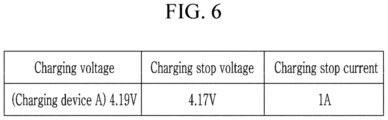
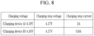
- FIGS. 6 to 9 are diagrams illustrating examples of charging stop voltage and charging stop current for each charging voltage of the charging device stored in the memory, respectively.
- the BMS 30 may disconnect the battery module 10 from charging device A and measure the charging voltage and the charging current of charging device A.
- the charging voltage of charging device A was measured at 4.19V and the charging current of charging device A was measured at 1.2A.
- the BMS 30 may check whether the charging voltage of 4.19V of charging device A is registered in the memory 32. If the charging voltage of 4.19V of charging device A is not registered in the memory 32, the BMS 30 may recognize charging device A as a new charging device.
- the BMS 30 may store a default value of 4.15V for the charging stop voltage and a default value of 1A for the charging stop current set as the design specifications of the battery pack 1 as the charging stop voltage and charging stop current for the charging voltage of 4.19V of the charging device A, respectively.
- the BMS 30 may connect the charging device A and the battery module 10 after checking the charging voltage of 4.19V of the charging device A.
- the battery module 10 may be connected to the charging device A and the battery pack 1 may be charged. Since the charging voltage of charging device A is 4.19V, the cell voltage of battery pack 1 may be increased.
- the BMS 30 may stop charging of the battery pack 1 if the cell voltage reaches the charging stop voltage of 4.15V of the charging device A in the CC section (and/or while using the CC method), and may measure the OCV of the cell if a set time has passed after stopping charging of the battery pack 1.
- the BMS 30 may increase the charging stop voltage from 4.15V to 4.17V. As shown in FIG. 6 , the BMS 30 may update the charging stop voltage for the charging voltage of 4.19 V of the charging device A stored in the memory 32 to the adjusted charging stop voltage of 4.17 V. At this time, the charging stop current of 1A for the charging voltage of 4.19V of charging device A stored in the memory 32 may remain the same.
- the charging device A was connected to the battery pack 1. If the BMS 30 recognizes the charging device A connected to the battery pack 1, it may disconnect the battery module 10 and the charging device A and may measure the charging voltage and charging current of the charging device A. The charging voltage of charging device A was measured at 4.19V and the charging current of charging device A was measured at 1.2A.
- the BMS 30 may check the stored charging stop voltage of 4.17V and charging stop current of 1A in response to the charging voltage of 4.19V of the charging device A in the memory 32.
- the BMS 30 may connect the charging device A and the battery module 10 after checking the charging voltage of 4.19V of the charging device A.
- the battery module 10 may be connected to the charging device A and the battery pack 1 may be charged. Since the charging voltage of charging device A is 4.19V, the cell voltage of battery pack 1 may be increased in the CC section and may reach the charging stop voltage of 4.17V of charging device A.
- the BMS 30 may stop charging of the battery pack 1 if the cell voltage reaches the charging stop voltage of 4.17V of charging device A in the CC section, and may measure the OCV of the cell if a set time has passed after stopping charging of the battery pack 1.
- the BMS 30 may terminate charging of the battery pack 1 and maintain the charging stop of the voltage charging device A at 4.17V. Accordingly, the charging stop voltage and charging stop current for the charging voltage of 4.19V of the charging device A stored in the memory 32 may be maintained at 4.17V and 1A, respectively, as shown in FIG. 6 .
- a charging device B was connected to the battery pack 1.
- the BMS 30 may disconnect the battery module 10 and the charging device B may measure the charging voltage and the charging current of the charging device B.
- the charging voltage of charging device B was measured at 4.16V and the charging current of charging device B was measured at 1.2A.
- the BMS 30 may check the charging stop voltage and charging stop current stored in response to the charging voltage of 4.16V in the memory 32. If the charging voltage of 4.16V is not registered in the memory 32, the BMS 30 may recognize charging device B as a new charging device. If the new charging device is recognized, the BMS 30 may store a default value of 4.15V for the charging stop voltage and a default value of 1A for the charging stop current set as the design specifications of the battery pack 1 as the charging stop voltage and charging stop current for the charging voltage of 4.16V of the charging device B, respectively.
- the BMS 30 may connect the charging device B and the battery module 10 in this example embodiment after checking the charging voltage of 4.16V of the charging device B.
- the battery module 10 may be connected to the charging device B and the battery pack 1 may be charged. Since the charging voltage of charging device B is 4.16V, the cell voltage of battery pack 1 may reach the charging stop voltage of 4.15V in the CC section.
- the BMS 30 may stop charging of the battery pack 1 if the cell voltage reaches the charging stop voltage of 4.15V of the charging device B in the CC section, and may measure the OCV of the cell if a set time has passed after stopping charging of the battery pack 1.
- the BMS 30 may increase the charging stop voltage from 4.15V to 4.17V. As shown in FIG. 7 , the BMS 30 may update the charging stop voltage for the charging voltage of 4.16 V of the charging device B stored in the memory 32 to the adjusted charging stop voltage of 4.17 V. At this time, the charging stop current of 1A for the charging voltage of 4.16V of the charging device B stored in the memory 32 may not change (that is, remain the same).
- the charging device B was connected to the battery pack 1. If the BMS 30 recognizes the charging device B connected to the battery pack 1, it may disconnect the battery module 10 and the charging device B and may measure the charging voltage and charging current of the charging device B. The charging voltage of charging device B was measured at 4.16V and the charging current of charging device B was measured at 1.2A.
- the BMS 30 may check the stored charging stop voltage of 4.17V and charging stop current of 1A in response to the charging voltage of 4.16V of the charging device B in the memory 32.
- the BMS 30 may connect charging device B and the battery module 10.
- the battery module 10 may be connected to the charging device B and the battery pack 1 may be charged. Since the charging voltage of 4.16V of charging device B is lower than the charging stop voltage of 4.17V, the cell voltage reaches the charging voltage of 4.16V of charging device B in the CC section, and the battery pack 1 may be charged by the CV method.
- the BMS 30 may check whether the cell current reaches the charging stop current of 1A in the CV section.
- the BMS 30 may stop charging of the battery pack 1 if the cell current reaches the charging stop current of 1A in the CV section and may measure the OCV of the cell if a set time has passed after stopping charging of the battery pack 1. If the OCV of the cell is 4.14V, the OCV of the cell does not reach the full charge voltage of 4.15V, so the BMS 30 may decrease the charging stop current from 1A to 0.8A.
- the BMS 30 in this example embodiment may update the charging stop current for the charging voltage of 4.16V stored in the memory 32 to the adjusted charging stop current of 0.8A. At this time, the charging stop voltage for the charging voltage of 4.16V stored in the memory 32 may not change (that is, remain the same).
- the charging device B was connected to the battery pack 1.
- the charging voltage of charging device B was measured at 4.16V and the charging current of charging device B was measured at 1.2A.
- the BMS 30 may check the stored charging stop voltage of 4.17V and charging stop current of 0.8A, in this example embodiment, in response to the charging voltage of 4.16V in the memory 32.
- the BMS 30 may connect charging device B and the battery module 10.
- the battery module 10 may be connected to the charging device B and the battery pack 1 may be charged. Since the charging voltage of 4.16V of charging device B is lower than the charging stop voltage of 4.17V, the cell voltage may be increased in the CC section and may reach the charging voltage of 4.16V, and the battery pack 1 may be charged by the CV method. The cell current may be reduced in the CV section.
- the BMS 30 may stop charging of the battery pack 1 if the cell current reaches the charging stop current of 0.8A in the CV section and may measure the OCV of the cell if a set time has passed after stopping charging of the battery pack 1.
- the BMS 30 may terminate charging of the battery pack 1, and may not change the charging stop voltage of 4.17V and the charge stop current of 0.8A for charging device B.
- the charging stop voltage and charging stop current for the charging voltage of 4.16V stored in the memory 32 may be maintained as shown in FIG. 8 .
- a charging device C was connected to the battery pack 1.
- the BMS 30 may disconnect the battery module 10 from charging device C and measure the charging voltage and the charging current of charging device C.
- the charging voltage of charging device C was measured at 4.165V and the charging current of charging device C was measured at 1.2A.
- the BMS 30 may check the stored charging stop voltage and charging stop current corresponding to the charging voltage of 4.165V of the charging device C in the memory 32. If the charging voltage of 4.165V of charging device C is not registered in the memory 32, the BMS 30 may recognize charging device C as a new charging device.
- the BMS 30 may store a default value of 4.15V for the charging stop voltage and a default value of 1A for the charging stop current set as the design specifications of the battery pack 1 as the charging stop voltage and charging stop current for the charging voltage of 4.165V of the charging device C, respectively.
- the BMS 30 may connect the charging device C and the battery module 10.
- the battery module 10 may be connected to the charging device C and the battery pack 1 may be charged. Since the charging voltage of charging device C is 4.165V, the cell voltage may reach the charging stop voltage of 4.15V in the CV section.
- the BMS 30 may stop charging of the battery pack 1 if the cell voltage reaches the charging stop voltage of 4.15V in the CC section, and may measure the OCV of the cell if a set time has passed after stopping charging of the battery pack 1. If the OCV of the cell is 4.13V, the OCV of the cell does not reach the full charge voltage of 4.15V, so the BMS 30 may increase the charging stop voltage of the charging device C from 4.15V to 4.17V.
- the BMS 30 of this example embodiment may update the charging stop voltage for the charging voltage of 4.165V of the charging device C stored in the memory 32 to the adjusted charge stop voltage of 4.17V.
- the charging stop current of 1A for the charging voltage of 4.165V of the charging device C stored in the memory 32 may not change (that is, remain the same).
- the charging device C was connected to the battery pack 1.
- the charging voltage of charging device C was measured to be 4.165V and the charging current of charging device C was measured to be 1.2A.
- the BMS 30 may check the stored charging stop voltage of 4.17V and charging stop current of 1A in response to the charging voltage of 4.165V of the charging device C in the memory 32.
- the BMS 30 may connect the charging device C and the battery module 10.
- the battery module 10 may be connected to the charging device C and the battery pack 1 may be charged. Since the charging voltage of 4.165V of charging device C is lower than the charging stop voltage of 4.17V, the cell voltage may reach the charging voltage of 4.165V in the CC section, and the battery pack 1 may be charged by the CV method.
- the BMS 30 may check whether the cell current reaches the charging stop current of 1A in the CV section.
- the BMS 30 may stop charging of the battery pack 1 if the cell current reaches the charging stop current of 1A in the CV section, and may measure the OCV of the cell if a set time has passed after stopping charging of the battery pack 1. If the OCV of the cell is 4.15V, the OCV of the cell reaches the full charge voltage of 4.15V, so the BMS 30 may terminate charging of the battery pack 1, and may maintain the charging stop voltage of 4.17V and the charge stop current of 0.8A for the charging voltage of 4.165V of charging device C.
- the charging stop voltage and charging stop current for the charging voltage of 4.165V of the charging device C stored in the memory 32 may be maintained as shown in FIG. 9 .
- the BMS 30 may distinguish each charging device using the charging voltage of each charging device, and may manage and adjust the charging stop voltage and charging stop current of the battery pack 1 according to the charging voltage. As a result, the charging amount may be maximized while preventing overcharging.
- FIG. 10 is a diagram showing an apparatus for controlling charge according to one or more embodiments.
- the apparatus 100 for controlling charge may include a cell voltage measurement part 110, a cell current measurement part 120, an OCV measurement part 130, a controller 140, and a storage part 150.
- the apparatus 100 for controlling charge may perform the functions of the BMS 30 described above.
- the apparatus 100 for controlling charge may be the BMS 30 or an apparatus implemented within the BMS 30.
- the cell voltage measurement part 110 may measure the cell voltage of the battery pack 1.
- the cell current measurement part 120 may measure the cell current of the battery pack 1.
- the OCV measurement part 130 may measure the OCV of the cell under the control of the controller 140.
- the controller 140 may measure a charging voltage of the charging device and may manage the charging stop voltage and charging stop current by using the charging voltage of the charging device as identification information of the charging device. The controller 140 may adjust the charging stop voltage and charging stop current for each charging voltage based on the charging control method described with reference to FIGS. 3 to 9 .
- the controller 140 may monitor the cell voltage measured by the cell voltage measurement part 110 and the cell current measured by the cell current measurement part 120, may stop charging of the battery pack 1 based on the cell voltage and cell current, and may change the stored charging stop voltage and charge stop current in response to the charging voltage of the charging device based on the cell voltage and cell current. If the charging stop voltage and charging stop current corresponding to the charging voltage of the charging device are not stored in the storage part 150, the controller 140 may use the default value of the charging stop voltage and the default value of the charging stop current corresponding to the design specifications of the battery pack 1.
- the storage part 150 may store the charging stop voltage and charging stop current using the charging voltage of the charging device as identification information of the charging device.
- the storage part 150 may be the memory 32 described above.
- FIG. 11 is a diagram showing an apparatus for controlling charge according to one or more other embodiments.
- the apparatus 200 for controlling charge may represent a computing device in which the method for controlling charge described above is implemented.
- the apparatus 200 for controlling charge may include at least one of a processor 210, a memory 220, an input interface device 230, an output interface device 240, and a storage device 250.
- Each component may be connected by a bus 260 and may communicate with each other. Additionally, each component may be connected through an individual interface or individual bus centered on the processor 210, rather than the common bus 260.
- the processor 210 may be implemented in various forms, such as an application processor (AP), a central processing unit (CPU), a graphics processing unit (GPU), etc., and may be any semiconductor device that executes a command stored in the memory 220 or storage device 250.
- the processor 210 may execute program commands stored in at least one of the memory 220 and the storage device 250. This processor 210 may be configured to implement the functions and methods described based on FIGS. 1 to 10 above.
- the memory 220 and the storage device 250 may include various types of volatile and/or non-volatile storage media.
- the memory 220 may include read-only memory (ROM) 221 and/or random access memory (RAM) 222.
- ROM read-only memory
- RAM random access memory
- the memory 220 may be located inside and/or outside the processor 210, and the memory 220 may be connected to the processor 210 through various known means, for example, signal lines.
- the input interface device 230 may be configured to provide data to the processor 210.
- the output interface device 240 may be configured to output data from the processor 210.
- overcharging may be prevented and the charging amount (for example, a capacity) may be increased to the maximum even when charging device abnormality or cell imbalance occurs.
- the charging amount for example, a capacity
- overcharging due to errors between charging devices may be prevented in an environment where various charging devices may be used, and the charging amount may be adjusted according to the charging device.
Landscapes
- Engineering & Computer Science (AREA)
- Power Engineering (AREA)
- Manufacturing & Machinery (AREA)
- Chemical & Material Sciences (AREA)
- Chemical Kinetics & Catalysis (AREA)
- Electrochemistry (AREA)
- General Chemical & Material Sciences (AREA)
- Secondary Cells (AREA)
- Charge And Discharge Circuits For Batteries Or The Like (AREA)
Abstract
An apparatus and method for controlling charging of a battery pack may be provided. A method for controlling charging of a battery pack including a plurality of cells in a battery management system may include checking identification information of a charging device connected to the battery pack; and controlling charging of the battery pack using the charging device based on a charging stop voltage and a charging stop current stored in response to the identification information of the charging device. An apparatus for controlling charge of a battery pack is also provided.
Description
- This disclosure relates to an apparatus and method for controlling charge of a battery pack.
- In order to maximize capacity of a battery, the battery must be charged to the maximum capacity according to the battery specifications.
- A normal charging device performs constant current (CC) charging and constant voltage (CV) charging according to design specifications, and can detect full charge with a reduced current value in the CV section. The CC section may also be referred to as CC charging method. Further, the CV section may also be referred to as CV charging method. However, if the charging voltage is greater than the design specification due to an error in the charging device, or a voltage of a specific cell rises above a certain voltage due to cell imbalance, it may not be possible to enter the CV section, or the reduced current value in the CV section is not met, a full charge condition may not be met even if it enters the CV section. Thus, the charging device may not detect full charge, and overcharge may occur.
- If overcharging is a one-time occurrence, there may be no major problem with the battery, but if a product with a built-in battery and a charging device are sold as a set, overcharging may occur each time the battery is charged. If the battery is maintained at high voltage due to overcharging, every time it is charged, it may be fatal to the deterioration and swelling of the battery.
- At least one of the embodiments may provide an apparatus and method for controlling charge of a battery pack that can prevent overcharging due to errors in the charging device.
- According to one embodiment, a method for controlling charging of a battery pack including a plurality of cells in a battery management system may be provided. The method for controlling charging includes checking identification information of a charging device connected to the battery pack; and controlling charging of the battery pack using the charging device based on a charging stop voltage and a charging stop current stored in response to the identification information of the charging device.
- In other words, the plurality of cells are controlled, that is charged and discharged, by the battery management system.
- Checking identification information may include disconnecting the battery pack and the charging device and measuring a charging voltage of the charging device; and setting the charging voltage of the charging device as the identification information of the charging device.
- Controlling charging of the battery pack may include monitoring a cell voltage of at least one first cell among the plurality of cells and a cell current flowing through the plurality of cells while the battery pack is being charged; and adjusting the charging stop voltage and the charging stop current based on the cell voltage and the cell current.
- Adjusting may include stopping charging if the cell voltage reaches the charging stop voltage; measuring an open circuit voltage of the first cell; and changing the charging stop voltage if the open circuit voltage of the first cell does not satisfy a full charge voltage of the battery pack.
- Satisfying a full charge may refer to that the nominal capacity of the cell has been reached. In other words, a full charge may not be satisfied if the nominal capacity of the cell has not been reached.
- Changing the charging stop voltage may include reducing the charging stop voltage by a set voltage; and updating the reduced charging stop voltage in response to the identification information of the charging device.
- Adjusting may further include stopping charging if the cell current reaches the charging stop current; measuring an open circuit voltage of at least one second cell among the plurality of cells; and changing the charging stop current if the open circuit voltage of the at least one second cell does not satisfy the full charge voltage of the battery pack.
- Changing the charging stop current may include reducing the charging stop current by a set current; and updating the reduced charging stop current in response to the identification information of the charging device.
- Controlling charging of the battery pack may include setting a default value of the charging stop voltage and a default value of the charging stop current set to specifications of the battery pack as initial values of the charging stop voltage and charging stop current corresponding to the identification information of the charging device.
- According to another embodiment, an apparatus for controlling charge of a battery pack may be provided. The apparatus for controlling charge includes a cell voltage measurement part that measures a cell voltage of each of a plurality of cells; a cell current measurement part that measures cell current flowing through the plurality of cells; a storage part that stores a charging stop voltage and a charging stop current for each identification information of a charging device; and a controller that checks identification information of a first charging device connected to the battery pack, controls charging of the battery pack using the first charging device based on a charging stop voltage and a charging stop current stored in response to the identification information of the charging device, and adjusts at least one of the charging stop voltage and the charging stop current stored in response to identification information of the first charging device based on the cell voltage and the cell current.
- According to an embodiment, the controller may disconnect the battery pack and the first charging device, measure a charging voltage of the first charging device, and may set the charging voltage of the first charging device as the identification information.
- According to another embodiment, the controller may disconnect the battery pack and the first charging device and measures a charging voltage of the first charging device, and may set the charging voltage of the first charging device as the identification information.
- According to an embodiment, the controller may update the charging stop voltage stored in response to the identification information of the first charging device to the reduced charge stop voltage.
- According to an embodiment, the controller may stop charging if the cell current reaches the charging stop current, may measure an open circuit voltage of a second cell among the plurality of cells, and may reduce the charging stop current if the open circuit voltage of the second cell does not satisfy a full charge voltage of the battery pack.
- According to an embodiment, the controller may update the charging stop current stored in response to the identification information of the first charging device to the reduced charging stop current.
- Features will become apparent to those of skill in the art by describing in detail exemplary embodiments with reference to the attached drawings in which:
-
FIG. 1 is a diagram showing a battery pack according to one or more embodiments. -
FIG. 2 is a diagram explaining a charging method of a battery module according to one or more embodiments. -
FIG. 3 is a flowchart showing a method for controlling charge in a BMS according to one or more embodiments. -
FIGS. 4 and5 are flowcharts showing a method for controlling charge according to one or more embodiments. -
FIGS. 6 to 9 are diagrams illustrating examples of charging stop voltage and charging stop current for each charging voltage of the charging device stored in the memory, respectively, according to one or more embodiments. -
FIG. 10 is a diagram showing an apparatus for controlling charge according to one or more embodiments. -
FIG. 11 is a diagram showing an apparatus for controlling charge according to one or more embodiments. - Example embodiments will now be described more fully hereinafter with reference to the accompanying drawings; however, they may be embodied in different forms and should not be construed as limited to the embodiments set forth herein. Rather, these embodiments are provided so that this disclosure will be thorough and complete, and will fully convey exemplary implementations to those skilled in the art. The drawings and description are to be regarded as illustrative in nature and not restrictive. Like reference numerals designate like elements throughout the specification. In the flowchart described with reference to the drawings in this specification, the order of operations may be changed, several operations may be merged, some operations may be divided, and specific operations may not be performed.
- Throughout the specification and claims, if a part is referred to "include" a certain element, it may mean that it may further include other elements rather than exclude other elements, unless specifically indicated otherwise.
- In addition, expressions described in the singular may be interpreted in the singular or plural unless explicit expressions such as "one" or "single" are used.
- In addition, terms including an ordinal number, such as first, second, etc., may be used to describe various elements, but the elements are not limited by the terms. The above terms are used only for the purpose of distinguishing one element from another element. For example, without departing from the scope of the present disclosure, a first element may be referred to as a second element, and similarly, a second element may be referred to as a first element.
- Furthermore, if a component is referred to as being "connected" with another component, it includes not only the case where two components are "directly connected" but also the case where two components are "indirectly or non-contactedly connected" with another component interposed therebetween, or the case where two components are "electrically connected." On the other hand, if an element is referred to as "directly connected" to another element, it should be understood that no other element exists in the middle.
-
FIG. 1 is a diagram showing a battery pack according to one or more embodiments. - Referring to
FIG. 1 , thebattery pack 1 may include at least onebattery module 10, aswitch 20, and a battery management system (BMS) 30. Thebattery pack 1 may further include terminals "T+" and "T-". "T+" may be referred to as the positive terminal and "T-" may be referred to as the negative terminal. - The
battery pack 1 may be connected to an external device through terminals "T+" and "T-". For example, thebattery pack 1 may be connected to a charging device or a load through terminals "T+" and "T-", and may be charged by the charging device and discharged by the load. - At least one
battery module 10 may include a plurality ofcells 11 electrically connected to each other in series and/or parallel. - The
switch 20 may be set to open or closed according to the switch control signal SCS supplied from theBMS 30, and may set or block the connection between thebattery module 10 and the external device. - The BMS 30 may control and manage the overall operation of the
battery pack 1. TheBMS 30 may monitor the overall status of thebattery module 10 and thecells 11 included in thebattery module 10, and may perform various control functions to adjust the status of thebattery module 10 and thecells 11 included in thebattery module 10. - The
BMS 30 may perform a cell balancing operation for the plurality ofcells 11 based on information such as cell voltages of the plurality ofcells 11 and battery current. TheBMS 30 may measure the voltages of the plurality ofcells 11 or receive the voltages of the plurality ofcells 11, for example, from a voltage sensor at thecell 11. TheBMS 30 may measure battery current or may receive battery current measured by a current sensor. - According to one or more embodiments, the
BMS 30 may identify a charging device for charging thebattery pack 1 and control charging of thebattery pack 1 based on the identification information of the charging device. If the charging device connected to thebattery pack 1 is recognized, theBMS 30 may control theswitch 20 to be open to open the charging path between thebattery module 10 and the charging device and measure the charging voltage of the charging device. TheBMS 30 may control charging of thebattery pack 1 by using the measured charging voltage of the charging device as identification information of the charging device. - The
BMS 30 may include amemory 32 that stores information about the charging device. In embodiments, thememory 32 may be a non-volatile memory (NVM). Information about the charging device may include information about identification information of the charging device (e.g., charging voltage of the charging device), charging stop voltage, and charging stop current. -
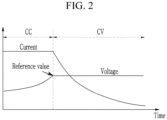
FIG. 2 is a diagram explaining a charging method of a battery module according to one or more embodiments. - Referring to
FIG. 2 , thebattery module 10 may be charged using a constant current (CC) method and a constant voltage (CV) method of a charging device. - If the charging device is connected to the
battery module 10, thebattery module 10 may be charged first using the CC method and then may be charged using the CV method. - In the CC section (area indicated by the dashed arrow labeled "CC") where charging by the CC method is performed, the charging device may maintain the amount of current flowing through the
battery module 10 constant according to CC conditions. At this time, the voltage of thebattery module 10 may be continuously increased. - As time passes and the voltage of the
battery module 10 reaches the reference value, it may be switched to charging by the CV method to prevent overvoltage and for safety. - In the CV section (area indicated by the dashed arrow labeled "CV") where charging by the CV method is performed, the charging device may maintain the voltage of the
battery module 10 constant, but the amount of current flowing through thebattery module 10 may be gradually decreased. - Afterwards, if a full charge is detected based on the current flowing through the
battery module 10, charging of thebattery module 10 may be completed. In general, the reference value for switching from the CC method to the CV method may be set higher than the charging stop voltage, which is the design specification of thebattery pack 1, and lower than the full charge voltage, which is the design specification of thebattery pack 1. - A normal charging device may detect full charge with a decreased current value in the CV section or when using the CV method. However, if the charging voltage becomes greater than the design specifications of the charging device due to an error in the charging device or the voltage of a specific cell may rise above a certain voltage due to cell imbalance, it may not be possible to enter the CV section (and/or proceed with the CV method) or even if it enters the CV section the current reduced in the CV section does not satisfy the full charge condition, so full charge may not be detected, and eventually overcharge may occur.
- If the
battery pack 1 continues to maintain high voltage due to overcharging, thebattery pack 1 may deteriorate. - The
BMS 30 may monitor the state of thecell 11 of thebattery module 10, may set the charging stop voltage for each charging device based on the state of thecell 11, and may control charging of thebattery pack 1 using the charging stop voltage. By controlling charging of thebattery pack 1 using the charging stop voltage, theBMS 30 according to one or more embodiments may maximize the charging amount while preventing overcharging of thebattery pack 1. The charging amount may be fraction of a capacity of thebattery pack 1 measured, for example, in mAh - Additionally, the
BMS 30 may set a charging stop current for each charging device and control charging of thebattery pack 1 using the charging stop current. By controlling charging using the charging stop current, theBMS 30 according to one or more embodiments may maximize the charging amount while preventing overcharging of thebattery pack 1. - Additionally, the
battery pack 1 may be charged using various charging devices. Each charging device has different specifications. In embodiments, theBMS 30 may identify each charging device and adjust the charging stop voltage and charging stop current for each charging device. -
FIG. 3 is a flowchart showing a method for controlling charge in a BMS according to one or more embodiment. - Referring to
FIG. 3 , if theBMS 30 recognizes that the charging device is connected to thebattery pack 1, it may check the identification information of the charging device. TheBMS 30 may disconnect thebattery module 10 and the charging device, may measure the charging voltage of the charging device (S302), and may set the charging voltage of the charging device as identification information of the charging device (S304). - The
BMS 30 may check whether the charging voltage of the charging device is registered in thememory 32. If the charging voltage of the charging device is not registered in thememory 32, theBMS 30 may recognize the charging device as a new charging device. If the charging device is recognized as a new charging device , theBMS 30 may store a default value of the charging stop voltage set as the design specification of thebattery pack 1 as the charging stop voltage corresponding to the charging voltage of the charging device. - The
battery module 10 and the charging device are connected, and thebattery module 10, that is, thebattery pack 1, may be charged using the CC method and CV method of the charging device. - The
BMS 30 may monitor a cell voltage while thebattery module 10 is charging (S306). In one or more embodiments, the cell voltage may mean the largest cell voltage among a plurality of cell voltages of thebattery module 10. Alternatively, the cell voltage may mean the average cell voltage of a plurality of cell voltages. - If the cell voltage reaches the set charging stop voltage (S308), the
BMS 30 may stop charging of the battery pack 1 (S310). TheBMS 30 may stop charging of thebattery pack 1 by controlling theswitch 20 to be open. - The
BMS 30 may measure an open circuit voltage (OCV) of the cell, for example, after a time (for example, a set time or a flexible time depending on the voltage change of the battery pack) has passed (S312). After the battery stops charging, the OCV may be measured when there is little change in current. The time may be several tens of minutes. In some embodiments, the time may be 20-30 minutes or more. - Next, the
BMS 30 may determine whether the OCV of the cell satisfies the full charge condition of the battery pack 1 (S314). The full charge condition may include a full charge voltage set as a design specification of thebattery pack 1. - If the OCV of the cell does not satisfy the full charge condition, the
BMS 30 may adjust the charging stop voltage (S316) and store the adjusted charge stop voltage in response to the identification information of the charging device in memory 32 (S318). - If the OCV of the cell satisfies the full charge condition, the
BMS 30 may terminate charging and maintain the charging stop voltage (S320). - The next time charging occurs, the
BMS 30 may control charging of thebattery pack 1 through the same process as steps S302 to S320. - In an example embodiment, in the design specifications of the
battery pack 1, assume that the full charge voltage, which is the full charge condition of thebattery pack 1, is set to 4.15V, the overcharge voltage of the cell is set to 4.2V, the charging stop voltage is set to 4.15V and the charging voltage of a charging device is 4.19V. - While the charging device is connected to the
battery pack 1 and thebattery pack 1 is being charged in this example embodiment, if the cell voltage reaches 4.15V, which is the charging stop voltage of thebattery pack 1 for the charging device, theBMS 30 may stop charging. TheBMS 30 may measure the OCV of the cell after a set time has passed. At this time, if the measured OCV is 4.13V and is less than 4.15V, which is the full charge voltage of thebattery pack 1, theBMS 30 may increase the charging stop voltage of thebattery pack 1 for the charging device from 4.15V to 4.17V. TheBMS 30 may store the charging stop voltage of 4.17V in thememory 32 in response to the identification information (4.19V) of the charging device. - Thereafter, if a charging device that provides a charging voltage of 4.19V is connected to the
battery pack 1 and thebattery pack 1 is charged, theBMS 30 may check (in other words, recognize) the charging voltage of the charging device as 4.19V, and may check the stored charging stop voltage of 4.17V corresponding to 4.19V from thememory 32. TheBMS 30 may stop charging if the cell voltage reaches the charging stop voltage of 4.17V, and may measure the OCV of the cell if a set time has passed after stopping charging. If the measured OCV is 4.15V, and reaches the full charge voltage of 4.15V, theBMS 30 may terminate charging of thebattery pack 1. TheBMS 30 may not change the stored charging stop voltage of 4.17V in response to the charging voltage of 4.19V of the charging device. However, according to another embodiment, if, after the set time has passed, the full charge voltage of, for example, 4.15V is not reached, the charging stop voltage may be changed. - In this way, the
BMS 30 may stop charging if the cell voltage reaches the charging stop voltage of thebattery pack 1 for the charging device, may measure the OCV of the cell, and may compare it to the full charge voltage. In this way, the charge amount of thebattery pack 1 may be maximized while preventing overcharging that occurs if the charging voltage becomes greater than the design specifications of the charging device due to an error in the charging device or the voltage of a specific cell rises above a certain voltage due to cell imbalance. - If the charging stop voltage of the
battery pack 1 for the charging device is adjusted, the charging voltage of the charging device may become lower than the adjusted charging stop voltage. In an example embodiment, the cell voltage may not reach the charging stop voltage of thebattery pack 1 for the charging device and the charging device may enter the CV section. - As an example, the charging voltage of the charging device is 4.16V, and the charging stop voltage for the charging device may be adjusted to 4.17V through the steps of
FIG. 3 . If the charging device that provides a charging voltage of 4.16V is connected to thebattery pack 1, the charging voltage of 4.16V of the charging device is lower than the charging stop voltage of 4.17V, so the charging device may enter the CV section if the cell voltage reaches the charging voltage of the charging device in the CC section and may charge thebattery pack 1 using the CV method. As a result, overcharging of thebattery pack 1 may occur in some cases. - According to one or more embodiment, the
BMS 30 may set a charging stop current to stop charging in the CV section along with the charging stop voltage, and may control the charging of thebattery pack 1 by adjusting the charging stop voltage and the charging stop current based on the cell voltage and battery current. -
FIGS. 4 and5 are flowcharts showing a method for controlling charge according to another embodiment. - Referring to
FIG. 4 , if theBMS 30 recognizes the connection of the charging device to thebattery pack 1, theBMS 30 may disconnect thebattery module 10 and the charging device and may measure the charging voltage of the charging device (S402). TheBMS 30 may set the charging voltage of the charging device as identification information of the charging device (S404). - The
BMS 30 may check whether the charging voltage of the charging device is registered in thememory 32. If the charging voltage of the charging device is not registered in thememory 32, theBMS 30 may recognize the charging device as a new charging device. If the charging device is recognized as a new charging device, theBMS 30 may store a default value of the charging stop voltage and a default value of the charging stop current set as the design specification of thebattery pack 1 as the charging stop voltage and the charging stop current corresponding to the charging voltage of the charging device, respectively. - While the
battery module 10 and the charging device are connected and thebattery pack 1 is charged in the CC method, theBMS 30 may monitor the cell voltage and cell current (S406). The cell current may represent the current of thebattery module 10, that is, the battery current. - The
BMS 30 may check whether the cell voltage has reached the charging stop voltage in the CC section (S408) and/or when using the cc method. - If the cell voltage does not reach the charging stop voltage in the CC section, the
BMS 30 may check whether the cell voltage in the CC section reaches the charging voltage of the charging device (S409). TheBMS 30 may perform step S406 if the cell voltage does not reach the charging voltage of the charging device in the CC section. - If the cell voltage reaches the charging voltage of the charging device in the CC section, the
BMS 30 may check whether the cell current reaches the charging stop current in the CV section (S410). If the cell voltage reaches the charging voltage of the charging device in the CC section, thebattery pack 1 may be charged using the CV method. The case where the cell current reaches the charging stop current will be described with reference toFIG. 5 . - Still referring to
FIG. 4 , theBMS 30 may stop charging of thebattery pack 1 if the cell voltage reaches the charging stop voltage (S412). - The
BMS 30 may measure the OCV of the cell if a set time has passed after stopping charging of thebattery pack 1. (S414). - Next, the
BMS 30 may determine whether the OCV of the cell satisfies the full charge condition of the battery pack 1 (S416). - If the OCV of the cell does not satisfy the full charge condition, the
BMS 30 may adjust the charging stop voltage (S418), and may store the adjusted charge stop voltage in response to the identification information of the charging device in memory 32 (S420). - If the OCV of the cell satisfies the full charge condition, the
BMS 30 may terminate charging and maintain the charging stop voltage (S422). - Referring to
FIG. 5 , theBMS 30 may stop charging of thebattery pack 1 if the cell current reaches the charging stop current of thebattery pack 1 in the CV section (S502). The cell current may decrease in the CV section, and if the cell current decreases to the charging stop current, theBMS 30 may stop charging of the battery pack 1 (S502). - The
BMS 30 may measure the OCV of the cell after a time (for example, a preset time or a flexible time depending on the voltage change of the battery pack) has passed after stopping charging of the battery pack 1 (S504). - The
BMS 30 may determine whether the OCV of the cell satisfies the full charge condition of the battery pack 1 (S506). - If the OCV of the cell does not satisfy the full charge condition, the
BMS 30 may adjust the charging stop current (S508) and may store the adjusted charging stop current in response to the charging voltage of the charging device in the memory 32 (S510). - in an example embodiment, assume that the full charge voltage, which is the full charge condition of the
battery pack 1, is set to 4.15V, the overcharge voltage of the cell is set to 4.2V, the default value of the charge stop voltage is set to 4.15V, and the default value of the charge stop current is set to 1A. The charging voltage of the charging device may be 4.16V. While the charging device is first connected to thebattery pack 1 and thebattery pack 1 is being charged, the cell voltage reached 4.15V, which is the full charge voltage, and charging was stopped at the charging stop voltage of 4.15V. However, after a set time had passed, the cell voltage was confirmed to be below the full charge voltage of 4.15V, and, accordingly, the charging stop voltage of the corresponding charging device may be adjusted to 4.17V and may be stored as an adjusted charging stop voltage of 4.17V in thememory 32. That is, the charging voltage of 4.16V of the charging device is lower than the charging stop voltage of 4.17V. Therefore, if the charging device is connected to thebattery module 10 again and thebattery pack 1 is charged, the charging device may enter the CV section (and/or the CV method) and charge thebattery pack 1. In the CV section (and/or the CV method), the cell current may decrease, and theBMS 30 may stop charging if the cell current reaches the charging stop current of 1A. TheBMS 30 may measure the OCV of the cell if a set time has passed after stopping charging. At this time, if the measured OCV of the cell is 4.14V, the OCV of the cell does not reaches the full charge voltage of 4.15V, so theBMS 30 may lower the charging stop current from 1A to 0.8A. TheBMS 30 may store the adjusted charging stop current of 0.8A in response to the charging voltage of 4.16V of the charging device in thememory 32. As the charging stop current is lowered from 1A to 0.8A and the charging stop current of 0.8A stored, theBMS 30 may control theswitch 20 to charge thebattery pack 1 until the OCV of the cell reaches the full charge voltage of 4.15V. In this way, theBMS 30 according to embodiments can maximize the amount of charge while preventing overcharging of thebattery pack 1. - Meanwhile, if the OCV of the cell satisfies the full charge condition, the
BMS 30 may terminate charging and maintain the charging stop current (S512). - The method for controlling charging shown in
FIGS. 4 and5 will be described in detail based onFIGS. 6 to 9 . - According to the design specifications of the
battery pack 1, in an example embodiment, assume that the full charge voltage corresponding to the full charge condition of thebattery pack 1 is set to 4.15V, the overcharge voltage of the cell is set to 4.2V, the default value of the charging stop voltage is set to 4.15V, and the default value of charging stop current is set to 1A. -
FIGS. 6 to 9 are diagrams illustrating examples of charging stop voltage and charging stop current for each charging voltage of the charging device stored in the memory, respectively. - For the first charge of the
battery pack 1, if charging device A is connected to thebattery pack 1, theBMS 30 may disconnect thebattery module 10 from charging device A and measure the charging voltage and the charging current of charging device A. The charging voltage of charging device A was measured at 4.19V and the charging current of charging device A was measured at 1.2A. - In this example embodiment, the
BMS 30 may check whether the charging voltage of 4.19V of charging device A is registered in thememory 32. If the charging voltage of 4.19V of charging device A is not registered in thememory 32, theBMS 30 may recognize charging device A as a new charging device. TheBMS 30 may store a default value of 4.15V for the charging stop voltage and a default value of 1A for the charging stop current set as the design specifications of thebattery pack 1 as the charging stop voltage and charging stop current for the charging voltage of 4.19V of the charging device A, respectively. - The
BMS 30 may connect the charging device A and thebattery module 10 after checking the charging voltage of 4.19V of the charging device A. Thebattery module 10 may be connected to the charging device A and thebattery pack 1 may be charged. Since the charging voltage of charging device A is 4.19V, the cell voltage ofbattery pack 1 may be increased. TheBMS 30 may stop charging of thebattery pack 1 if the cell voltage reaches the charging stop voltage of 4.15V of the charging device A in the CC section (and/or while using the CC method), and may measure the OCV of the cell if a set time has passed after stopping charging of thebattery pack 1. If the OCV of the cell is 4.13V, the OCV of the cell does not reach the full charge voltage of 4.15V, so theBMS 30 may increase the charging stop voltage from 4.15V to 4.17V. As shown inFIG. 6 , theBMS 30 may update the charging stop voltage for the charging voltage of 4.19 V of the charging device A stored in thememory 32 to the adjusted charging stop voltage of 4.17 V. At this time, the charging stop current of 1A for the charging voltage of 4.19V of charging device A stored in thememory 32 may remain the same. - For the second charging of the
battery pack 1, in another example embodiment, the charging device A was connected to thebattery pack 1. If theBMS 30 recognizes the charging device A connected to thebattery pack 1, it may disconnect thebattery module 10 and the charging device A and may measure the charging voltage and charging current of the charging device A. The charging voltage of charging device A was measured at 4.19V and the charging current of charging device A was measured at 1.2A. - In this example embodiment, the
BMS 30 may check the stored charging stop voltage of 4.17V and charging stop current of 1A in response to the charging voltage of 4.19V of the charging device A in thememory 32. - The
BMS 30 may connect the charging device A and thebattery module 10 after checking the charging voltage of 4.19V of the charging device A. Thebattery module 10 may be connected to the charging device A and thebattery pack 1 may be charged. Since the charging voltage of charging device A is 4.19V, the cell voltage ofbattery pack 1 may be increased in the CC section and may reach the charging stop voltage of 4.17V of charging device A. TheBMS 30 may stop charging of thebattery pack 1 if the cell voltage reaches the charging stop voltage of 4.17V of charging device A in the CC section, and may measure the OCV of the cell if a set time has passed after stopping charging of thebattery pack 1. If the OCV of the cell is 4.15V, the OCV of the cell reaches the full charge voltage of 4.15V, so theBMS 30 may terminate charging of thebattery pack 1 and maintain the charging stop of the voltage charging device A at 4.17V. Accordingly, the charging stop voltage and charging stop current for the charging voltage of 4.19V of the charging device A stored in thememory 32 may be maintained at 4.17V and 1A, respectively, as shown inFIG. 6 . - For the third charging of the
battery pack 1 in a further example embodiment, a charging device B was connected to thebattery pack 1. TheBMS 30 may disconnect thebattery module 10 and the charging device B may measure the charging voltage and the charging current of the charging device B. The charging voltage of charging device B was measured at 4.16V and the charging current of charging device B was measured at 1.2A. - Continuing with this example embodiment, the
BMS 30 may check the charging stop voltage and charging stop current stored in response to the charging voltage of 4.16V in thememory 32. If the charging voltage of 4.16V is not registered in thememory 32, theBMS 30 may recognize charging device B as a new charging device. If the new charging device is recognized, theBMS 30 may store a default value of 4.15V for the charging stop voltage and a default value of 1A for the charging stop current set as the design specifications of thebattery pack 1 as the charging stop voltage and charging stop current for the charging voltage of 4.16V of the charging device B, respectively. - The
BMS 30 may connect the charging device B and thebattery module 10 in this example embodiment after checking the charging voltage of 4.16V of the charging device B. Thebattery module 10 may be connected to the charging device B and thebattery pack 1 may be charged. Since the charging voltage of charging device B is 4.16V, the cell voltage ofbattery pack 1 may reach the charging stop voltage of 4.15V in the CC section. TheBMS 30 may stop charging of thebattery pack 1 if the cell voltage reaches the charging stop voltage of 4.15V of the charging device B in the CC section, and may measure the OCV of the cell if a set time has passed after stopping charging of thebattery pack 1. If the OCV of the cell is 4.13V, the OCV of the cell does not reach the full charge voltage of 4.15V, so theBMS 30 may increase the charging stop voltage from 4.15V to 4.17V. As shown inFIG. 7 , theBMS 30 may update the charging stop voltage for the charging voltage of 4.16 V of the charging device B stored in thememory 32 to the adjusted charging stop voltage of 4.17 V. At this time, the charging stop current of 1A for the charging voltage of 4.16V of the charging device B stored in thememory 32 may not change (that is, remain the same). - For the fourth charging of the
battery pack 1, in another example embodiment, the charging device B was connected to thebattery pack 1. If theBMS 30 recognizes the charging device B connected to thebattery pack 1, it may disconnect thebattery module 10 and the charging device B and may measure the charging voltage and charging current of the charging device B. The charging voltage of charging device B was measured at 4.16V and the charging current of charging device B was measured at 1.2A. - Continuing with this example embodiment, the
BMS 30 may check the stored charging stop voltage of 4.17V and charging stop current of 1A in response to the charging voltage of 4.16V of the charging device B in thememory 32. - After checking the charging voltage of 4.16V of charging device B, the
BMS 30 may connect charging device B and thebattery module 10. Thebattery module 10 may be connected to the charging device B and thebattery pack 1 may be charged. Since the charging voltage of 4.16V of charging device B is lower than the charging stop voltage of 4.17V, the cell voltage reaches the charging voltage of 4.16V of charging device B in the CC section, and thebattery pack 1 may be charged by the CV method. - If the cell voltage in this example embodiment reaches the charging voltage of 4.16V of charging device B in the CC section, the
BMS 30 may check whether the cell current reaches the charging stop current of 1A in the CV section. TheBMS 30 may stop charging of thebattery pack 1 if the cell current reaches the charging stop current of 1A in the CV section and may measure the OCV of the cell if a set time has passed after stopping charging of thebattery pack 1. If the OCV of the cell is 4.14V, the OCV of the cell does not reach the full charge voltage of 4.15V, so theBMS 30 may decrease the charging stop current from 1A to 0.8A. - As shown in
FIG. 8 , theBMS 30 in this example embodiment may update the charging stop current for the charging voltage of 4.16V stored in thememory 32 to the adjusted charging stop current of 0.8A. At this time, the charging stop voltage for the charging voltage of 4.16V stored in thememory 32 may not change (that is, remain the same). - For the fifth charging of the
battery pack 1, in still another example embodiment, the charging device B was connected to thebattery pack 1. The charging voltage of charging device B was measured at 4.16V and the charging current of charging device B was measured at 1.2A. - The
BMS 30 may check the stored charging stop voltage of 4.17V and charging stop current of 0.8A, in this example embodiment, in response to the charging voltage of 4.16V in thememory 32. - After checking the charging voltage of 4.16V of charging device B in this example embodiment, the
BMS 30 may connect charging device B and thebattery module 10. Thebattery module 10 may be connected to the charging device B and thebattery pack 1 may be charged. Since the charging voltage of 4.16V of charging device B is lower than the charging stop voltage of 4.17V, the cell voltage may be increased in the CC section and may reach the charging voltage of 4.16V, and thebattery pack 1 may be charged by the CV method. The cell current may be reduced in the CV section. TheBMS 30 may stop charging of thebattery pack 1 if the cell current reaches the charging stop current of 0.8A in the CV section and may measure the OCV of the cell if a set time has passed after stopping charging of thebattery pack 1. If the OCV of the cell is 4.15V, the OCV of the cell reaches the full charge voltage of 4.15V, so theBMS 30 may terminate charging of thebattery pack 1, and may not change the charging stop voltage of 4.17V and the charge stop current of 0.8A for charging device B. The charging stop voltage and charging stop current for the charging voltage of 4.16V stored in thememory 32 may be maintained as shown inFIG. 8 . - For the sixth charging of the
battery pack 1 in yet another example embodiment, a charging device C was connected to thebattery pack 1. TheBMS 30 may disconnect thebattery module 10 from charging device C and measure the charging voltage and the charging current of charging device C. The charging voltage of charging device C was measured at 4.165V and the charging current of charging device C was measured at 1.2A. TheBMS 30 may check the stored charging stop voltage and charging stop current corresponding to the charging voltage of 4.165V of the charging device C in thememory 32. If the charging voltage of 4.165V of charging device C is not registered in thememory 32, theBMS 30 may recognize charging device C as a new charging device. If a new charging device may be recognized, theBMS 30 may store a default value of 4.15V for the charging stop voltage and a default value of 1A for the charging stop current set as the design specifications of thebattery pack 1 as the charging stop voltage and charging stop current for the charging voltage of 4.165V of the charging device C, respectively. - After checking the charging voltage of 4.165V of the charging device C, in this example embodiment, the
BMS 30 may connect the charging device C and thebattery module 10. Thebattery module 10 may be connected to the charging device C and thebattery pack 1 may be charged. Since the charging voltage of charging device C is 4.165V, the cell voltage may reach the charging stop voltage of 4.15V in the CV section. TheBMS 30 may stop charging of thebattery pack 1 if the cell voltage reaches the charging stop voltage of 4.15V in the CC section, and may measure the OCV of the cell if a set time has passed after stopping charging of thebattery pack 1. If the OCV of the cell is 4.13V, the OCV of the cell does not reach the full charge voltage of 4.15V, so theBMS 30 may increase the charging stop voltage of the charging device C from 4.15V to 4.17V. - As shown in
FIG. 9 , theBMS 30 of this example embodiment may update the charging stop voltage for the charging voltage of 4.165V of the charging device C stored in thememory 32 to the adjusted charge stop voltage of 4.17V. At this time, the charging stop current of 1A for the charging voltage of 4.165V of the charging device C stored in thememory 32 may not change (that is, remain the same). - During the seventh charging of the
battery pack 1, in a further example embodiment, the charging device C was connected to thebattery pack 1. In theBMS 30, the charging voltage of charging device C was measured to be 4.165V and the charging current of charging device C was measured to be 1.2A. - The
BMS 30 may check the stored charging stop voltage of 4.17V and charging stop current of 1A in response to the charging voltage of 4.165V of the charging device C in thememory 32. - After checking the charging voltage of 4.165V of the charging device C, in this example embodiment, the
BMS 30 may connect the charging device C and thebattery module 10. Thebattery module 10 may be connected to the charging device C and thebattery pack 1 may be charged. Since the charging voltage of 4.165V of charging device C is lower than the charging stop voltage of 4.17V, the cell voltage may reach the charging voltage of 4.165V in the CC section, and thebattery pack 1 may be charged by the CV method. - If the cell voltage reaches the charging voltage of 4.165V in the CC section of this example embodiment, the
BMS 30 may check whether the cell current reaches the charging stop current of 1A in the CV section. TheBMS 30 may stop charging of thebattery pack 1 if the cell current reaches the charging stop current of 1A in the CV section, and may measure the OCV of the cell if a set time has passed after stopping charging of thebattery pack 1. If the OCV of the cell is 4.15V, the OCV of the cell reaches the full charge voltage of 4.15V, so theBMS 30 may terminate charging of thebattery pack 1, and may maintain the charging stop voltage of 4.17V and the charge stop current of 0.8A for the charging voltage of 4.165V of charging device C. The charging stop voltage and charging stop current for the charging voltage of 4.165V of the charging device C stored in thememory 32 may be maintained as shown inFIG. 9 . - In this way, the
BMS 30 may distinguish each charging device using the charging voltage of each charging device, and may manage and adjust the charging stop voltage and charging stop current of thebattery pack 1 according to the charging voltage. As a result, the charging amount may be maximized while preventing overcharging. -
FIG. 10 is a diagram showing an apparatus for controlling charge according to one or more embodiments. - Referring to
FIG. 10 , theapparatus 100 for controlling charge may include a cellvoltage measurement part 110, a cellcurrent measurement part 120, anOCV measurement part 130, acontroller 140, and astorage part 150. Theapparatus 100 for controlling charge may perform the functions of theBMS 30 described above. Theapparatus 100 for controlling charge may be theBMS 30 or an apparatus implemented within theBMS 30. - The cell
voltage measurement part 110 may measure the cell voltage of thebattery pack 1. - The cell
current measurement part 120 may measure the cell current of thebattery pack 1. - The
OCV measurement part 130 may measure the OCV of the cell under the control of thecontroller 140. - If a charging device is connected to the
battery pack 1, thecontroller 140 may measure a charging voltage of the charging device and may manage the charging stop voltage and charging stop current by using the charging voltage of the charging device as identification information of the charging device. Thecontroller 140 may adjust the charging stop voltage and charging stop current for each charging voltage based on the charging control method described with reference toFIGS. 3 to 9 . - If the
battery pack 1 is connected to a charging device and charged, thecontroller 140 may monitor the cell voltage measured by the cellvoltage measurement part 110 and the cell current measured by the cellcurrent measurement part 120, may stop charging of thebattery pack 1 based on the cell voltage and cell current, and may change the stored charging stop voltage and charge stop current in response to the charging voltage of the charging device based on the cell voltage and cell current. If the charging stop voltage and charging stop current corresponding to the charging voltage of the charging device are not stored in thestorage part 150, thecontroller 140 may use the default value of the charging stop voltage and the default value of the charging stop current corresponding to the design specifications of thebattery pack 1. - The
storage part 150 may store the charging stop voltage and charging stop current using the charging voltage of the charging device as identification information of the charging device. Thestorage part 150 may be thememory 32 described above. -
FIG. 11 is a diagram showing an apparatus for controlling charge according to one or more other embodiments. - Referring to
FIG. 11 , theapparatus 200 for controlling charge may represent a computing device in which the method for controlling charge described above is implemented. - The
apparatus 200 for controlling charge may include at least one of aprocessor 210, amemory 220, aninput interface device 230, anoutput interface device 240, and astorage device 250. Each component may be connected by abus 260 and may communicate with each other. Additionally, each component may be connected through an individual interface or individual bus centered on theprocessor 210, rather than thecommon bus 260. - The
processor 210 may be implemented in various forms, such as an application processor (AP), a central processing unit (CPU), a graphics processing unit (GPU), etc., and may be any semiconductor device that executes a command stored in thememory 220 orstorage device 250. Theprocessor 210 may execute program commands stored in at least one of thememory 220 and thestorage device 250. Thisprocessor 210 may be configured to implement the functions and methods described based onFIGS. 1 to 10 above. - The
memory 220 and thestorage device 250 may include various types of volatile and/or non-volatile storage media. For example, thememory 220 may include read-only memory (ROM) 221 and/or random access memory (RAM) 222. In an embodiment, thememory 220 may be located inside and/or outside theprocessor 210, and thememory 220 may be connected to theprocessor 210 through various known means, for example, signal lines. - The
input interface device 230 may be configured to provide data to theprocessor 210. - The
output interface device 240 may be configured to output data from theprocessor 210. - According to at least one of the embodiments, overcharging may be prevented and the charging amount (for example, a capacity) may be increased to the maximum even when charging device abnormality or cell imbalance occurs.
- Additionally, according to at least one of the embodiments, overcharging due to errors between charging devices may be prevented in an environment where various charging devices may be used, and the charging amount may be adjusted according to the charging device.
- Although the embodiments of the present disclosure have been described in detail above, the scope of the present disclosure is not limited thereto, and various modifications and improvements of those skilled in the art using the basic concepts of the present disclosure defined in the claims are also included in the present disclosure.
-
- 10: Battery pack
- 11: Cell
- 20: Switch
- 30: BMS
- 32: Memory
- 100: Apparatus for controlling charge
- 110: Cell voltage measurement part
- 120: Cell current measurement part
- 130: OCV measurement part
- 140: Controller
- 150: Storage part
Claims (15)
- A method for controlling charging of a battery pack (1) including a plurality of cells (11) in a battery management system (30), the method comprising:checking identification information of a charging device connected to the battery pack (1); andcontrolling charging of the battery pack (1) using the charging device based on a charging stop voltage and a charging stop current stored in response to the identification information of the charging device.
- The method as claimed in claim 1, wherein the checking comprises:disconnecting the battery pack (1) and the charging device and measuring a charging voltage of the charging device; andsetting the charging voltage of the charging device as the identification information of the charging device.
- The method as claimed in claim 1 or claim 2, wherein the controlling charging of the battery pack (1) comprises:monitoring a cell voltage of at least one first cell (11) among the plurality of cells (11) and a cell current flowing through the plurality of cells (11) while the battery pack (1) is being charged; andadjusting the charging stop voltage and the charging stop current based on the cell voltage and the cell (11) current.
- The method as claimed in claim 3, wherein the adjusting comprises:stopping charging if the cell voltage reaches the charging stop voltage;measuring an open circuit voltage of the first cell (11); andchanging the charging stop voltage if the open circuit voltage of the first cell (11) does not satisfy a full charge voltage of the battery pack (1).
- The method as claimed in claim 4, wherein the changing the charging stop voltage comprises:reducing the charging stop voltage by a set voltage; andupdating the reduced charging stop voltage in response to the identification information of the charging device.
- The method as claimed in any one of claims 3 to 5, wherein the adjusting further comprises:stopping charging if the cell (11) current reaches the charging stop current;measuring an open circuit voltage of at least one second cell (11) among the plurality of cells (11); andchanging the charging stop current if the open circuit voltage of the at least one second cell (11) does not satisfy the full charge voltage of the battery pack (1).
- The method as claimed in claim 6, wherein the changing the charging stop current comprises:reducing the charging stop current by a set current; andupdating the reduced charging stop current in response to the identification information of the charging device.
- The method as claimed in any one of claims 1 to 7, wherein the controlling charging of the battery pack (1) comprises:setting a default value of the charging stop voltage and a default value of the charging stop current set to specifications of the battery pack (1) as initial values of the charging stop voltage and charging stop current corresponding to the identification information of the charging device.
- An apparatus for controlling charge (100, 200) of a battery pack (1), the apparatus comprising:a cell voltage measurement part (110) configured to measure a cell voltage of each of a plurality of cells (11);a cell current measurement part (120) configured to measure cell current flowing through the plurality of cells (11);a storage part (150) configured to store a charging stop voltage and a charging stop current for each identification information of a charging device; anda controller (140) configured to check identification information of a charging device connected to the battery pack (1), and to control charging of the battery pack (1) using the charging device based on a charging stop voltage and a charging stop current stored in response to the identification information of the charging device.
- The apparatus for controlling charge (100, 200) as claimed in claim 9, wherein the controller (140) is further configured to adjust at least one of the charging stop voltage and the charging stop current stored in response to identification information of the charging device based on the cell voltage and the cell current.
- The apparatus for controlling charge (100, 200) as claimed in claim 9 or 10, wherein
the controller (140) is configured to disconnect the battery pack (1) and the charging device, measure a charging voltage of the charging device, and set the charging voltage of the charging device as the identification information. - The apparatus for controlling charge (100, 200) as claimed in any one of claims 9 to 11, wherein
the controller (140) is configured to stop charging if a cell voltage of a first cell (11) among the plurality of cells (11) reaches the charging stop voltage, measure an open circuit voltage of the first cell (11), and reduce the charging stop voltage if the open circuit voltage of the first cell (11) does not satisfy a full charge voltage of the battery pack (1). - The apparatus for controlling charge (100, 200) as claimed in claim 12, wherein
the controller (140) is configured to update the charging stop voltage stored in response to the identification information of the charging device to the reduced charge stop voltage. - The apparatus for controlling charge (100, 200) as claimed in any one of claims 9 to 13, wherein
the controller (140) is configured to stop charging if the cell current reaches the charging stop current, measure an open circuit voltage of a second cell (11) among the plurality of cells (11), and reduce the charging stop current if the open circuit voltage of the second cell (11) does not satisfy a full charge voltage of the battery pack (1). - The apparatus for controlling charge (100, 200) as claimed in claim 14, wherein
the controller (140) is configured to update the charging stop current stored in response to the identification information of the charging device to the reduced charging stop current.
Applications Claiming Priority (1)
| Application Number | Priority Date | Filing Date | Title |
|---|---|---|---|
| KR1020230178033A KR20250088194A (en) | 2023-12-08 | 2023-12-08 | Apparatus and method for controlling charge of battery pack |
Publications (1)
| Publication Number | Publication Date |
|---|---|
| EP4568057A1 true EP4568057A1 (en) | 2025-06-11 |
Family
ID=92593386
Family Applications (1)
| Application Number | Title | Priority Date | Filing Date |
|---|---|---|---|
| EP24196920.3A Pending EP4568057A1 (en) | 2023-12-08 | 2024-08-28 | Apparatus and method for controlling charge of battery pack |
Country Status (4)
| Country | Link |
|---|---|
| US (1) | US20250192579A1 (en) |
| EP (1) | EP4568057A1 (en) |
| KR (1) | KR20250088194A (en) |
| CN (1) | CN120127779A (en) |
Citations (3)
| Publication number | Priority date | Publication date | Assignee | Title |
|---|---|---|---|---|
| WO2018095683A1 (en) * | 2016-11-23 | 2018-05-31 | Robert Bosch Gmbh | Method for fast charging lithium-ion batteries |
| US20210228040A1 (en) * | 2018-06-26 | 2021-07-29 | Makita Corporation | Rechargeable cleaner |
| KR20220063804A (en) * | 2020-11-09 | 2022-05-18 | (주)대륜엔지니어링 | A Smart Safety System for Electric Vehicle Charger |
-
2023
- 2023-12-08 KR KR1020230178033A patent/KR20250088194A/en active Pending
-
2024
- 2024-03-11 US US18/600,984 patent/US20250192579A1/en active Pending
- 2024-08-20 CN CN202411144177.9A patent/CN120127779A/en active Pending
- 2024-08-28 EP EP24196920.3A patent/EP4568057A1/en active Pending
Patent Citations (3)
| Publication number | Priority date | Publication date | Assignee | Title |
|---|---|---|---|---|
| WO2018095683A1 (en) * | 2016-11-23 | 2018-05-31 | Robert Bosch Gmbh | Method for fast charging lithium-ion batteries |
| US20210228040A1 (en) * | 2018-06-26 | 2021-07-29 | Makita Corporation | Rechargeable cleaner |
| KR20220063804A (en) * | 2020-11-09 | 2022-05-18 | (주)대륜엔지니어링 | A Smart Safety System for Electric Vehicle Charger |
Also Published As
| Publication number | Publication date |
|---|---|
| US20250192579A1 (en) | 2025-06-12 |
| CN120127779A (en) | 2025-06-10 |
| KR20250088194A (en) | 2025-06-17 |
Similar Documents
| Publication | Publication Date | Title |
|---|---|---|
| EP2418751B1 (en) | Battery charger and battery charging method | |
| EP0926799B1 (en) | Power supply apparatus | |
| US12467979B2 (en) | Abnormal cell diagnosing method and battery system applying the same | |
| EP4290730A1 (en) | Battery management device and method | |
| US20260110739A1 (en) | Battery State Management Apparatus and Operating Method Thereof | |
| KR20210051461A (en) | Battery management system and method for determining over voltage of battery cell | |
| US20220060030A1 (en) | Power Feeding Control Device, Power Feeding System, and Power Feeding Method | |
| US12288977B2 (en) | Fusion bonding protecting module and battery system including the same | |
| EP4568057A1 (en) | Apparatus and method for controlling charge of battery pack | |
| US7612540B2 (en) | Lithium-ion battery diagnostic and prognostic techniques | |
| EP4246160A1 (en) | Battery management device and method | |
| KR20210041282A (en) | Charge/discharge switch control method and battery system whrer the method is applied | |
| KR20240085830A (en) | Battery system and battery management method using the same | |
| JP2024519689A (en) | Battery management device and method of operation thereof | |
| EP4307516B1 (en) | Battery management apparatus and method | |
| US20230268747A1 (en) | Circuit for measuring battery cell voltage and control method thereof | |
| EP4614661A1 (en) | Battery system and method for controlling connection between battery packs using same | |
| EP4303600A1 (en) | Voltage determination circuit | |
| EP4447258A1 (en) | Device and method for controlling charging of battery pack | |
| KR20250000923A (en) | Battery controlling apparatus and method for control related to charging and discharging battery packs connected in parallel each other | |
| KR20250120700A (en) | Battery diagnosis apparatus and operating method of the same | |
| KR20240093233A (en) | Battery management apparatus and operating method of the same | |
| KR20250097496A (en) | Battery management apparatus and operating method of the same | |
| KR20210157104A (en) | Method of preventing melt bonding and battery system where the method is applied | |
| WO2021117560A1 (en) | Electricity storage device and electricity storage method |
Legal Events
| Date | Code | Title | Description |
|---|---|---|---|
| PUAI | Public reference made under article 153(3) epc to a published international application that has entered the european phase |
Free format text: ORIGINAL CODE: 0009012 |
|
| STAA | Information on the status of an ep patent application or granted ep patent |
Free format text: STATUS: REQUEST FOR EXAMINATION WAS MADE |
|
| 17P | Request for examination filed |
Effective date: 20240828 |
|
| AK | Designated contracting states |
Kind code of ref document: A1 Designated state(s): AL AT BE BG CH CY CZ DE DK EE ES FI FR GB GR HR HU IE IS IT LI LT LU LV MC ME MK MT NL NO PL PT RO RS SE SI SK SM TR |