EP4568040A1 - Vehicle electric system including an emc filtering device - Google Patents
Vehicle electric system including an emc filtering device Download PDFInfo
- Publication number
- EP4568040A1 EP4568040A1 EP24217419.1A EP24217419A EP4568040A1 EP 4568040 A1 EP4568040 A1 EP 4568040A1 EP 24217419 A EP24217419 A EP 24217419A EP 4568040 A1 EP4568040 A1 EP 4568040A1
- Authority
- EP
- European Patent Office
- Prior art keywords
- electrical connection
- filtering
- electric
- printed circuit
- circuit board
- Prior art date
- Legal status (The legal status is an assumption and is not a legal conclusion. Google has not performed a legal analysis and makes no representation as to the accuracy of the status listed.)
- Pending
Links
Images
Classifications
-
- B—PERFORMING OPERATIONS; TRANSPORTING
- B60—VEHICLES IN GENERAL
- B60R—VEHICLES, VEHICLE FITTINGS, OR VEHICLE PARTS, NOT OTHERWISE PROVIDED FOR
- B60R16/00—Electric or fluid circuits specially adapted for vehicles and not otherwise provided for; Arrangement of elements of electric or fluid circuits specially adapted for vehicles and not otherwise provided for
- B60R16/02—Electric or fluid circuits specially adapted for vehicles and not otherwise provided for; Arrangement of elements of electric or fluid circuits specially adapted for vehicles and not otherwise provided for electric constitutive elements
- B60R16/03—Electric or fluid circuits specially adapted for vehicles and not otherwise provided for; Arrangement of elements of electric or fluid circuits specially adapted for vehicles and not otherwise provided for electric constitutive elements for supply of electrical power to vehicle subsystems or for
- B60R16/033—Electric or fluid circuits specially adapted for vehicles and not otherwise provided for; Arrangement of elements of electric or fluid circuits specially adapted for vehicles and not otherwise provided for electric constitutive elements for supply of electrical power to vehicle subsystems or for characterised by the use of electrical cells or batteries
-
- H—ELECTRICITY
- H02—GENERATION; CONVERSION OR DISTRIBUTION OF ELECTRIC POWER
- H02J—ELECTRIC POWER NETWORKS; CIRCUIT ARRANGEMENTS OR SYSTEMS FOR SUPPLYING OR DISTRIBUTING ELECTRIC POWER; SYSTEMS FOR STORING ELECTRIC ENERGY
- H02J1/00—Circuit arrangements for DC mains or DC distribution networks
- H02J1/02—Arrangements for reducing harmonics or ripples
-
- H—ELECTRICITY
- H01—ELECTRIC ELEMENTS
- H01R—ELECTRICALLY-CONDUCTIVE CONNECTIONS; STRUCTURAL ASSOCIATIONS OF A PLURALITY OF MUTUALLY-INSULATED ELECTRICAL CONNECTING ELEMENTS; COUPLING DEVICES; CURRENT COLLECTORS
- H01R12/00—Structural associations of a plurality of mutually-insulated electrical connecting elements, specially adapted for printed circuits, e.g. printed circuit boards [PCB], flat or ribbon cables, or like generally planar structures, e.g. terminal strips, terminal blocks; Coupling devices specially adapted for printed circuits, flat or ribbon cables, or like generally planar structures; Terminals specially adapted for contact with, or insertion into, printed circuits, flat or ribbon cables, or like generally planar structures
- H01R12/70—Coupling devices
- H01R12/71—Coupling devices for rigid printing circuits or like structures
-
- H—ELECTRICITY
- H01—ELECTRIC ELEMENTS
- H01R—ELECTRICALLY-CONDUCTIVE CONNECTIONS; STRUCTURAL ASSOCIATIONS OF A PLURALITY OF MUTUALLY-INSULATED ELECTRICAL CONNECTING ELEMENTS; COUPLING DEVICES; CURRENT COLLECTORS
- H01R13/00—Details of coupling devices of the kinds covered by groups H01R12/70 or H01R24/00 - H01R33/00
- H01R13/02—Contact members
- H01R13/22—Contacts for co-operating by abutting
- H01R13/24—Contacts for co-operating by abutting resilient; resiliently-mounted
- H01R13/2407—Contacts for co-operating by abutting resilient; resiliently-mounted characterized by the resilient means
- H01R13/2414—Contacts for co-operating by abutting resilient; resiliently-mounted characterized by the resilient means conductive elastomers
-
- H—ELECTRICITY
- H01—ELECTRIC ELEMENTS
- H01R—ELECTRICALLY-CONDUCTIVE CONNECTIONS; STRUCTURAL ASSOCIATIONS OF A PLURALITY OF MUTUALLY-INSULATED ELECTRICAL CONNECTING ELEMENTS; COUPLING DEVICES; CURRENT COLLECTORS
- H01R4/00—Electrically-conductive connections between two or more conductive members in direct contact, i.e. touching one another; Means for effecting or maintaining such contact; Electrically-conductive connections having two or more spaced connecting locations for conductors and using contact members penetrating insulation
- H01R4/02—Soldered or welded connections
- H01R4/029—Welded connections
-
- H—ELECTRICITY
- H01—ELECTRIC ELEMENTS
- H01R—ELECTRICALLY-CONDUCTIVE CONNECTIONS; STRUCTURAL ASSOCIATIONS OF A PLURALITY OF MUTUALLY-INSULATED ELECTRICAL CONNECTING ELEMENTS; COUPLING DEVICES; CURRENT COLLECTORS
- H01R4/00—Electrically-conductive connections between two or more conductive members in direct contact, i.e. touching one another; Means for effecting or maintaining such contact; Electrically-conductive connections having two or more spaced connecting locations for conductors and using contact members penetrating insulation
- H01R4/28—Clamped connections, spring connections
- H01R4/48—Clamped connections, spring connections utilising a spring, clip, or other resilient member
- H01R4/4809—Clamped connections, spring connections utilising a spring, clip, or other resilient member using a leaf spring to bias the conductor toward the busbar
- H01R4/4811—Spring details
-
- H—ELECTRICITY
- H01—ELECTRIC ELEMENTS
- H01R—ELECTRICALLY-CONDUCTIVE CONNECTIONS; STRUCTURAL ASSOCIATIONS OF A PLURALITY OF MUTUALLY-INSULATED ELECTRICAL CONNECTING ELEMENTS; COUPLING DEVICES; CURRENT COLLECTORS
- H01R4/00—Electrically-conductive connections between two or more conductive members in direct contact, i.e. touching one another; Means for effecting or maintaining such contact; Electrically-conductive connections having two or more spaced connecting locations for conductors and using contact members penetrating insulation
- H01R4/28—Clamped connections, spring connections
- H01R4/48—Clamped connections, spring connections utilising a spring, clip, or other resilient member
- H01R4/4809—Clamped connections, spring connections utilising a spring, clip, or other resilient member using a leaf spring to bias the conductor toward the busbar
- H01R4/4846—Busbar details
- H01R4/485—Single busbar common to multiple springs
-
- H—ELECTRICITY
- H02—GENERATION; CONVERSION OR DISTRIBUTION OF ELECTRIC POWER
- H02J—ELECTRIC POWER NETWORKS; CIRCUIT ARRANGEMENTS OR SYSTEMS FOR SUPPLYING OR DISTRIBUTING ELECTRIC POWER; SYSTEMS FOR STORING ELECTRIC ENERGY
- H02J7/00—Circuit arrangements for charging or discharging batteries or for supplying loads from batteries
- H02J7/60—Circuit arrangements for charging or discharging batteries or for supplying loads from batteries including safety or protection arrangements
- H02J7/64—Circuit arrangements for charging or discharging batteries or for supplying loads from batteries including safety or protection arrangements against overvoltage
-
- H—ELECTRICITY
- H05—ELECTRIC TECHNIQUES NOT OTHERWISE PROVIDED FOR
- H05K—PRINTED CIRCUITS; CASINGS OR CONSTRUCTIONAL DETAILS OF ELECTRIC APPARATUS; MANUFACTURE OF ASSEMBLAGES OF ELECTRICAL COMPONENTS
- H05K1/00—Printed circuits
- H05K1/02—Details
- H05K1/14—Structural association of two or more printed circuits
- H05K1/144—Stacked arrangements of planar printed circuit boards
-
- H—ELECTRICITY
- H05—ELECTRIC TECHNIQUES NOT OTHERWISE PROVIDED FOR
- H05K—PRINTED CIRCUITS; CASINGS OR CONSTRUCTIONAL DETAILS OF ELECTRIC APPARATUS; MANUFACTURE OF ASSEMBLAGES OF ELECTRICAL COMPONENTS
- H05K1/00—Printed circuits
- H05K1/18—Printed circuits structurally associated with non-printed electric components
-
- H—ELECTRICITY
- H02—GENERATION; CONVERSION OR DISTRIBUTION OF ELECTRIC POWER
- H02J—ELECTRIC POWER NETWORKS; CIRCUIT ARRANGEMENTS OR SYSTEMS FOR SUPPLYING OR DISTRIBUTING ELECTRIC POWER; SYSTEMS FOR STORING ELECTRIC ENERGY
- H02J2105/00—Networks for supplying or distributing electric power characterised by their spatial reach or by the load
- H02J2105/30—Networks for supplying or distributing electric power characterised by their spatial reach or by the load the load networks being external to vehicles, i.e. exchanging power with vehicles
-
- H—ELECTRICITY
- H02—GENERATION; CONVERSION OR DISTRIBUTION OF ELECTRIC POWER
- H02M—APPARATUS FOR CONVERSION BETWEEN AC AND AC, BETWEEN AC AND DC, OR BETWEEN DC AND DC, AND FOR USE WITH MAINS OR SIMILAR POWER SUPPLY SYSTEMS; CONVERSION OF DC OR AC INPUT POWER INTO SURGE OUTPUT POWER; CONTROL OR REGULATION THEREOF
- H02M1/00—Details of apparatus for conversion
- H02M1/44—Circuits or arrangements for compensating for electromagnetic interference in converters or inverters
Definitions
- the invention relates to a vehicle electric system.
- the invention relates to a vehicle electric system of the type comprising at least one electric/electronic apparatus; a power supply device, normally a battery, to electrically power the electric/electronic apparatus; an electrical connection device to connect the power supply device and the electric/electronic apparatus to one another; and a filtering device associated with the electrical connection device to at least limit interfering voltages and/or currents generated by the electric/electronic apparatus itself.
- the electrical connection device comprises a busbar provided with a plurality of conductor bars made of a metal material, for example copper or aluminium; and the filtering device comprises a passive EMC (Electromagnetic Compatibility) filter provided with a printed circuit board and with a plurality of electronic components, in particular capacitors and inductances, mounted on the printed circuit board and electrically connected to one another through the printed circuit board.
- EMC Electromagnetic Compatibility
- the object of the invention is to provide a vehicle electric system that is not affected by the aforementioned drawbacks and can be manufactured in a simple and economic fashion.
- number 1 indicates, as a whole, a vehicle electric system mounted in a road vehicle (not shown).
- the electric system 1 comprises a first electric/electronic apparatus 2; a second electric/electronic apparatus 3; and a power supply device 4, normally a battery, to electrically power the apparatuses 2 and 3.
- the electric system 1 further comprises an electrical connection device 5 to connect the power supply device 4 and the apparatus 2 to one another; and a filtering device 6 associated with the device 5 to at least limit interfering voltages and/or currents generated by the apparatus 2.
- the device 5 comprises a busbar 7 having a plurality of bars 8 made of a conductive material (in this case, two bars 8), each having an input 9 connected to the device 4 and an output 10 connected to the apparatus 2.
- the device 6 comprises a plurality of filtering modules 11 (in this case, two modules 11), which are mounted in series to one another, can be connected to one another in a releasable manner and are configured to limit respective interfering voltages and/or currents having different frequencies from one another.
- the two filtering modules 11 have different cut-off frequencies (in particular, they are configured to filter different frequency bands).
- each module acts upon given frequencies adding up to what is filtered by the adjacent module.
- the two filtering modules 11 are arranged in sequence (not in contact with one another) along a longitudinal axis of the bars 8.
- each filtering module 11 acts upon both bars 8 of the busbar 7.
- Each filtering module 11 is (completely) crossed by the busbar 7, in particular, each filtering module 11 radially surrounds the busbar 7 and, hence, the bars 8.
- Each module 11 comprises a passive EMC (Electromagnetic Compatibility) filter provided with a printed circuit board 12 with a flat shape, which extends parallel to the printed circuit board 12 of the other module 11, is connected to the printed circuit board 12 of the other module 11 in a releasable manner by means of a plurality of fastening screws 13 and is delimited by two main faces 14, 15 opposite one another.
- EMC Electromagnetic Compatibility
- the module 11 is further provided with a plurality of electronic components 16 mounted on the printed circuit board 12 and electrically connected to one another through the printed circuit board 12.
- each module 11 comprise, in this specific case, a central inductance 17 with a tubular shape, which is fixed to the face 14 of the printed circuit board 12 and extends around the bars 8, and a plurality of side capacitors 18, which are mounted on the face 14 of the printed circuit board 12 and are arranged around the inductance 17.
- the bars 8 extend perpendicularly to the printed circuit boards 12 and through an opening 19 obtained in each printed circuit board 12.
- the electric system 1 further comprises, for each module 11, a respective plurality of electrical connection members 20 to power the module 11 with the electric current supplied through the bars 8 of the electrical connection device 5.
- Each member 20 comprises an elastic connection element defined by a shaped leaf spring 21, which is made of a conductive material, is interposed between the electrical connection device 5 and the filtering device 6 and has a first end 22 fixed, in this case welded, to the inner wall of the opening 19 of the relative printed circuit board 12 and a second end 23 electrically connected to a relative bar 8 through mechanical interference.
- a shaped leaf spring 21 which is made of a conductive material
- the electrical connection between the bars 8 of the electrical connection device 5 and the printed circuit boards 12 of the filtering modules 11 allows the filtering device 6 to at least limit interfering voltages and/or currents with different frequencies generated by the apparatus 2 and, therefore, to guarantee the correct operation of the apparatus 3.
- the inductance 17 has shapes other than the circular one, for example the shape of a parallelepiped, and is manufactured as one piece or two pieces connected to one another, for example through gluing.
Landscapes
- Engineering & Computer Science (AREA)
- Mechanical Engineering (AREA)
- Power Engineering (AREA)
- Microelectronics & Electronic Packaging (AREA)
- Filters And Equalizers (AREA)
Abstract
A vehicle electric system has an electrical connection device (5) to connect a power supply device (4) and at least one electric/electronic apparatus (2, 3) to one another, and a filtering device (6), which is associated with the electrical connection device (5) to at least limit interfering voltages and/or currents generated by the electric/electronic apparatus (2, 3), is powered with the electric current supplied through the electrical connection device (5) and is provided with at least two filtering modules (11) mounted in series to one another and connected to one another in a releasable manner.
Description
- This patent application claims priority from
Italian patent application no. 102023000026118 filed on December 6, 2023 - The invention relates to a vehicle electric system.
- In particular, the invention relates to a vehicle electric system of the type comprising at least one electric/electronic apparatus; a power supply device, normally a battery, to electrically power the electric/electronic apparatus; an electrical connection device to connect the power supply device and the electric/electronic apparatus to one another; and a filtering device associated with the electrical connection device to at least limit interfering voltages and/or currents generated by the electric/electronic apparatus itself.
- Generally speaking, the electrical connection device comprises a busbar provided with a plurality of conductor bars made of a metal material, for example copper or aluminium; and the filtering device comprises a passive EMC (Electromagnetic Compatibility) filter provided with a printed circuit board and with a plurality of electronic components, in particular capacitors and inductances, mounted on the printed circuit board and electrically connected to one another through the printed circuit board.
- Known vehicle electric systems of the type described above suffer from some drawbacks, which are mainly due to the fact that the limitation of interfering voltages and/or currents having different frequencies leads to the use of a plurality of filtering devices and makes said vehicle electric systems relatively large-sized, complex and expensive.
- The object of the invention is to provide a vehicle electric system that is not affected by the aforementioned drawbacks and can be manufactured in a simple and economic fashion.
- According to the invention, there is provided a vehicle electric system as claimed in the appended claims.
- The invention will now be described with reference to the accompanying drawings showing a non-limiting embodiment thereof, wherein:
-
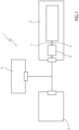
figure 1 schematically shows a preferred embodiment of the vehicle electric system according to the invention; and -
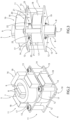
figures 2 and 3 show two schematic perspective views, with parts removed for greater clarity, of a detail of the vehicle electric system offigure 1 . - With reference to
figure 1 , number 1 indicates, as a whole, a vehicle electric system mounted in a road vehicle (not shown). - The electric system 1 comprises a first electric/
electronic apparatus 2; a second electric/electronic apparatus 3; and apower supply device 4, normally a battery, to electrically power theapparatuses - The electric system 1 further comprises an
electrical connection device 5 to connect thepower supply device 4 and theapparatus 2 to one another; and afiltering device 6 associated with thedevice 5 to at least limit interfering voltages and/or currents generated by theapparatus 2. - The
device 5 comprises abusbar 7 having a plurality ofbars 8 made of a conductive material (in this case, two bars 8), each having aninput 9 connected to thedevice 4 and anoutput 10 connected to theapparatus 2. - The
device 6 comprises a plurality of filtering modules 11 (in this case, two modules 11), which are mounted in series to one another, can be connected to one another in a releasable manner and are configured to limit respective interfering voltages and/or currents having different frequencies from one another. In other words, the twofiltering modules 11 have different cut-off frequencies (in particular, they are configured to filter different frequency bands). - Advantageously, though not in a limiting manner, each module acts upon given frequencies adding up to what is filtered by the adjacent module.
- In particular, with modules mounted in series, the two
filtering modules 11 are arranged in sequence (not in contact with one another) along a longitudinal axis of thebars 8. - More in particular, each
filtering module 11 acts upon bothbars 8 of thebusbar 7. Eachfiltering module 11 is (completely) crossed by thebusbar 7, in particular, eachfiltering module 11 radially surrounds thebusbar 7 and, hence, thebars 8. - Each
module 11 comprises a passive EMC (Electromagnetic Compatibility) filter provided with a printedcircuit board 12 with a flat shape, which extends parallel to theprinted circuit board 12 of theother module 11, is connected to theprinted circuit board 12 of theother module 11 in a releasable manner by means of a plurality offastening screws 13 and is delimited by twomain faces - The
module 11 is further provided with a plurality ofelectronic components 16 mounted on the printedcircuit board 12 and electrically connected to one another through the printedcircuit board 12. - The
electronic components 16 of eachmodule 11 comprise, in this specific case, acentral inductance 17 with a tubular shape, which is fixed to theface 14 of the printedcircuit board 12 and extends around thebars 8, and a plurality ofside capacitors 18, which are mounted on theface 14 of the printedcircuit board 12 and are arranged around theinductance 17. - With regard to what discussed above, it should be pointed out that the
bars 8 extend perpendicularly to the printedcircuit boards 12 and through an opening 19 obtained in eachprinted circuit board 12. - The electric system 1 further comprises, for each
module 11, a respective plurality ofelectrical connection members 20 to power themodule 11 with the electric current supplied through thebars 8 of theelectrical connection device 5. - Each
member 20 comprises an elastic connection element defined by ashaped leaf spring 21, which is made of a conductive material, is interposed between theelectrical connection device 5 and thefiltering device 6 and has afirst end 22 fixed, in this case welded, to the inner wall of the opening 19 of the relative printedcircuit board 12 and asecond end 23 electrically connected to arelative bar 8 through mechanical interference. - In use, the electrical connection between the
bars 8 of theelectrical connection device 5 and the printedcircuit boards 12 of thefiltering modules 11 allows thefiltering device 6 to at least limit interfering voltages and/or currents with different frequencies generated by theapparatus 2 and, therefore, to guarantee the correct operation of theapparatus 3. - With regard to what discussed above, it should be pointed out that, according to alternative embodiments that are not shown herein, the
inductance 17 has shapes other than the circular one, for example the shape of a parallelepiped, and is manufactured as one piece or two pieces connected to one another, for example through gluing.
Claims (11)
- A vehicle electric system comprising at least one electric/electronic apparatus (2, 3); a power supply device (4) to electrically power the electric/electronic apparatus (2, 3); an electrical connection device (5) to connect the power supply device (4) and the electric/electronic apparatus (2, 3) to one another; a filtering device (6) associated with the electrical connection device (5) to at least limit interfering voltages and/or currents generated by said electric/electronic apparatus (2, 3); and electrical connection means (20) to power the filtering device (6) with the electric current supplied through the electrical connection device (5); and characterized in that the filtering device (6) comprises at least two filtering modules (11) mounted in series to one another and coupling means (13) to connect the filtering modules (11) to one another in a releasable manner.
- The system according to claim 1, wherein the filtering modules (11) are configured to limit respective interfering voltages and/or currents having different frequencies from one another.
- The system according to claim 1 or 2, wherein the electrical connection means (20) comprise, for each filtering module (11), at least one respective elastic connection element (21) made of conductive material and interposed between the electrical connection device (5) and the filtering module (11).
- The system according to claim 3, wherein each elastic connection element (21) comprises a spring fixed to the relative filtering module (11) and stressed in a compressive manner by the electrical connection device (5).
- The system according to any one of the preceding claims, wherein the electrical connection (5) comprises a busbar (7).
- The system according to any one of the preceding claims, wherein each filtering module (11) comprises a passive EMC (Electromagnetic Compatibility) filter.
- The system according to any one of the preceding claims, wherein each filtering module (11) comprises a printed circuit board (12) and a plurality of electronic components (16), in particular inductances (17) and capacitors (18), mounted on the printed circuit board (12) and electrically connected to one another through the printed circuit board (12).
- The system according to claim 7, wherein the electrical connection device (5) comprises at least one conductor bar (8) mounted between the power supply device (4) and said electric/electronic apparatus (2, 3), and the electrical connection means (20) comprise, for each filtering module (11), at least one respective elastic connection element (21) made of a conductive material and interposed between the printed circuit board (12) of the filtering module (11) and a relative conductor bar (8).
- The system according to claim 8, wherein each electric connection element (21) comprises a shaped leaf spring having a first end (22) fixed to the printed circuit board (12) and a second end (23) electrically connected to the relative conductor bar (8) through mechanical interference.
- The system according to claim 8 or 9, wherein each filtering module (6) comprises at least one inductance (17) with an annular shape mounted on the printed circuit board (12), and wherein each conductor bar (8) extends through the inductances (17).
- The system according to claim 10, wherein each conductor bar (8) extends perpendicularly to and through the printed circuit boards (12) of the filtering modules (11) .
Applications Claiming Priority (1)
| Application Number | Priority Date | Filing Date | Title |
|---|---|---|---|
| IT102023000026118A IT202300026118A1 (en) | 2023-12-06 | 2023-12-06 | VEHICLE ELECTRICAL SYSTEM |
Publications (1)
| Publication Number | Publication Date |
|---|---|
| EP4568040A1 true EP4568040A1 (en) | 2025-06-11 |
Family
ID=89845399
Family Applications (1)
| Application Number | Title | Priority Date | Filing Date |
|---|---|---|---|
| EP24217419.1A Pending EP4568040A1 (en) | 2023-12-06 | 2024-12-04 | Vehicle electric system including an emc filtering device |
Country Status (4)
| Country | Link |
|---|---|
| US (1) | US20250187555A1 (en) |
| EP (1) | EP4568040A1 (en) |
| CN (1) | CN120109560A (en) |
| IT (1) | IT202300026118A1 (en) |
Citations (3)
| Publication number | Priority date | Publication date | Assignee | Title |
|---|---|---|---|---|
| US20180049314A1 (en) * | 2016-08-12 | 2018-02-15 | Schaffner Emv Ag | Filter comprising printed circuit board and busbars |
| WO2022124649A1 (en) * | 2020-12-10 | 2022-06-16 | 엘지이노텍 주식회사 | Electronic control device |
| CN218123905U (en) * | 2022-07-12 | 2022-12-23 | 法雷奥新能源汽车(常熟)有限公司 | Busbar assemblies, electrical equipment, electric drivetrains and vehicles |
Family Cites Families (1)
| Publication number | Priority date | Publication date | Assignee | Title |
|---|---|---|---|---|
| DE102023101144A1 (en) * | 2023-01-18 | 2024-07-18 | Avl Software And Functions Gmbh | Filter for suppressing common mode interference and/or differential mode interference |
-
2023
- 2023-12-06 IT IT102023000026118A patent/IT202300026118A1/en unknown
-
2024
- 2024-12-03 US US18/966,944 patent/US20250187555A1/en active Pending
- 2024-12-04 EP EP24217419.1A patent/EP4568040A1/en active Pending
- 2024-12-06 CN CN202411788076.5A patent/CN120109560A/en active Pending
Patent Citations (4)
| Publication number | Priority date | Publication date | Assignee | Title |
|---|---|---|---|---|
| US20180049314A1 (en) * | 2016-08-12 | 2018-02-15 | Schaffner Emv Ag | Filter comprising printed circuit board and busbars |
| WO2022124649A1 (en) * | 2020-12-10 | 2022-06-16 | 엘지이노텍 주식회사 | Electronic control device |
| US20240107687A1 (en) * | 2020-12-10 | 2024-03-28 | Lg Innotek Co., Ltd. | Electronic control device |
| CN218123905U (en) * | 2022-07-12 | 2022-12-23 | 法雷奥新能源汽车(常熟)有限公司 | Busbar assemblies, electrical equipment, electric drivetrains and vehicles |
Also Published As
| Publication number | Publication date |
|---|---|
| IT202300026118A1 (en) | 2025-06-06 |
| US20250187555A1 (en) | 2025-06-12 |
| CN120109560A (en) | 2025-06-06 |
Similar Documents
| Publication | Publication Date | Title |
|---|---|---|
| US10404040B2 (en) | Filter arrangement | |
| US10694619B2 (en) | Filter comprising printed circuit board and busbars | |
| EP3925071B1 (en) | Filter module for reducing differential and common mode noise and method to manufacture such a filter module | |
| US8884719B2 (en) | Noise filter device | |
| CN111344823B (en) | DC link capacitor module, power electronic module and power electronic device | |
| EP3503136B1 (en) | Multi-purpose power conversion module | |
| US12424797B2 (en) | EMC filter plug-in arrangement | |
| EP3493227A1 (en) | Inductor component and power supply module | |
| CN201656757U (en) | Multi-path input/output AC/DC power supply and signal wire filtering filter | |
| US20250187555A1 (en) | Vehicle electric system | |
| KR101664667B1 (en) | Output terminal with improved emc feature | |
| JP2016504736A (en) | Electronic substrate manufacturing and assembly process and electronic device obtained thereby | |
| JP2017085300A (en) | Capacitor unit | |
| EP3493336B1 (en) | A male electrical connector for a voltage converter | |
| EP4568041A1 (en) | Vehicle electric system including an emc filtering device | |
| US7177436B2 (en) | Component arranged directly on a t-coil | |
| JP2017120822A (en) | Output noise reduction device | |
| US4737745A (en) | Electromagnetic interference filter assembly | |
| CN111800103B (en) | Power filter and electronic equipment | |
| JP3791686B2 (en) | Shield case | |
| EP3824701B1 (en) | Battery charger for vehicles and relative realization process | |
| CN222914570U (en) | Punching capacitor set | |
| EP3557770A1 (en) | Electric interconnector system | |
| CN113424394B (en) | System for contactless transmission of electrical power to a mobile device | |
| CN120855872A (en) | EMC filter components for power converters and power converters |
Legal Events
| Date | Code | Title | Description |
|---|---|---|---|
| PUAI | Public reference made under article 153(3) epc to a published international application that has entered the european phase |
Free format text: ORIGINAL CODE: 0009012 |
|
| STAA | Information on the status of an ep patent application or granted ep patent |
Free format text: STATUS: THE APPLICATION HAS BEEN PUBLISHED |
|
| AK | Designated contracting states |
Kind code of ref document: A1 Designated state(s): AL AT BE BG CH CY CZ DE DK EE ES FI FR GB GR HR HU IE IS IT LI LT LU LV MC ME MK MT NL NO PL PT RO RS SE SI SK SM TR |
|
| STAA | Information on the status of an ep patent application or granted ep patent |
Free format text: STATUS: REQUEST FOR EXAMINATION WAS MADE |
|
| 17P | Request for examination filed |
Effective date: 20251211 |