EP4568017A1 - Reflection device and system - Google Patents
Reflection device and system Download PDFInfo
- Publication number
- EP4568017A1 EP4568017A1 EP23857268.9A EP23857268A EP4568017A1 EP 4568017 A1 EP4568017 A1 EP 4568017A1 EP 23857268 A EP23857268 A EP 23857268A EP 4568017 A1 EP4568017 A1 EP 4568017A1
- Authority
- EP
- European Patent Office
- Prior art keywords
- reflection apparatus
- base body
- units
- reflection
- reflected wave
- Prior art date
- Legal status (The legal status is an assumption and is not a legal conclusion. Google has not performed a legal analysis and makes no representation as to the accuracy of the status listed.)
- Granted
Links
Images



Classifications
-
- H—ELECTRICITY
- H01—ELECTRIC ELEMENTS
- H01Q—ANTENNAS, i.e. RADIO AERIALS
- H01Q3/00—Arrangements for changing or varying the orientation or the shape of the directional pattern of the waves radiated from an antenna or antenna system
- H01Q3/44—Arrangements for changing or varying the orientation or the shape of the directional pattern of the waves radiated from an antenna or antenna system varying the electric or magnetic characteristics of reflecting, refracting, or diffracting devices associated with the radiating element
- H01Q3/46—Active lenses or reflecting arrays
-
- H—ELECTRICITY
- H01—ELECTRIC ELEMENTS
- H01Q—ANTENNAS, i.e. RADIO AERIALS
- H01Q15/00—Devices for reflection, refraction, diffraction or polarisation of waves radiated from an antenna, e.g. quasi-optical devices
- H01Q15/0006—Devices acting selectively as reflecting surface, as diffracting or as refracting device, e.g. frequency filtering or angular spatial filtering devices
- H01Q15/0013—Devices acting selectively as reflecting surface, as diffracting or as refracting device, e.g. frequency filtering or angular spatial filtering devices said selective devices working as frequency-selective reflecting surfaces, e.g. FSS, dichroic plates, surfaces being partly transmissive and reflective
-
- H—ELECTRICITY
- H01—ELECTRIC ELEMENTS
- H01Q—ANTENNAS, i.e. RADIO AERIALS
- H01Q15/00—Devices for reflection, refraction, diffraction or polarisation of waves radiated from an antenna, e.g. quasi-optical devices
- H01Q15/14—Reflecting surfaces; Equivalent structures
- H01Q15/148—Reflecting surfaces; Equivalent structures with means for varying the reflecting properties
Definitions
- the present invention relates to a reflection apparatus and a system.
- Patent Document 1 a reflector array in which a large number of elements as small as a wavelength are arranged in a planar shape is described as a reflector that reflects radio waves.
- Patent Document 1 Japanese Patent Application Publication No. 2015-46821
- a reflection apparatus reflects a radio wave.
- the reflection apparatus includes a first device and a second device which are provided along an emission direction of a reflected wave.
- the first device includes a plurality of first units each including a first base body which has a first surface and a second surface provided along the emission direction of the reflected wave, a first element which is provided on the first surface, and a second element which is provided on the second surface to be shifted in position from the first element in the emission direction of the reflected wave.
- the second device includes a plurality of second units each including a second base body which has a third surface and a fourth surface provided along the emission direction of the reflected wave, a third element which is provided on the third surface, and a fourth element which is provided on the fourth surface.
- the first device is provided separated from the second device, and a relative positional relationship between the first device and the second device in a direction along the second surface is adjustable.
- a phase of the reflected wave may be determined by surface areas of the first element and the second element, a relative positional relationship between the first element and the second element, a thickness of the first base body, surface areas of the third element and the fourth element, and a thickness of the second base body.
- the plurality of first units and the plurality of second units may be provided at a plurality of positions along a specific direction along the first surface, such that phases of the reflected wave are different from each other.
- the plurality of first units and the plurality of second units may be provided such that the reflected wave propagates in a specific direction.
- Any of the reflection apparatuses may further include an adjustment apparatus which adjusts a relative positional relationship between the first device and the second device.
- a length of one side of each of the plurality of first units may be 0.3 ⁇ or more and 0.6 ⁇ or less where ⁇ is a wavelength of a radio wave incident on the reflection apparatus.
- the first element, the second element, and the third element each may have a polygonal shape or a shape curved at least in part.
- the first element may transmit a specific linearly polarized wave or a specific circularly polarized wave.
- the first base body and the second base body each may have a polygonal shape or a shape curved at least in part.
- the first element and the third element may be conductors having a frequency selective surface (FSS).
- FSS frequency selective surface
- a system includes any of the reflection apparatuses.
- the system includes a radio wave radiation apparatus which radiates a radio wave incident on the reflection apparatus.
- radio waves in a relatively high frequency band are used. Since radio waves in a high frequency band have high straightness, it is difficult for the radio waves to diffract around an obstacle such as a building to reach a shadow zone. For this reason, many coverage holes (areas in which communication cannot be performed) are generated in an area that is invisible from a base station, and a communication coverage area may be narrowed. Therefore, in order to expand the communication coverage area, it is necessary to install a large number of base stations. Accordingly, a cost for expanding the communication area increases.
- a reflector is provided in a construction such as a building, and a radio wave radiated from a base station is reflected by the reflector, so that the radio wave can reach an area which is the shadow zone of the obstacle.
- a meta-surface reflector capable of making an incident angle and a reflection angle of a radio wave different has been studied.
- the reflection apparatus 30 has a structure in which the first device 110 and the second device 120 are separated from each other. This allows for adjusting the relative in-plane positions of the first device 110 and the second device 120, thereby enabling the adjustment of the phase of the reflected wave. Accordingly, the manufacturing cost of the reflection apparatus 30 is reduced, while power for maintaining the reflection angle of the radio wave in a specific direction becomes substantially unnecessary. Furthermore, in the reflection apparatus 30, an additional element is provided between the first device 100 and the second device 200, thereby enabling the expansion of the phase change amount of the reflected wave in an operation frequency band. Accordingly, it becomes possible to expand a communication coverage area through a base station. Therefore, the number of base stations can be suppressed, so that the cost for expanding the communication coverage area can be reduced.
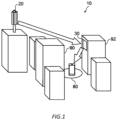
- Fig. 1 schematically shows an example of a configuration of the system 10 including the reflection apparatus 30.
- the system 10 includes a base station 20 and the reflection apparatus 30.
- the system 10 is a mobile communication system.
- the base station 20 radiates radio waves for mobile communication.
- the radio waves radiated by the base station 20 include a radio wave in a frequency band that can be used in the 5th generation mobile communication system.
- the radio waves radiated by the base station 20 may include a radio wave in a frequency band equal to or higher than the frequency band of the S-band.
- the radio waves radiated by the base station 20 may include a radio wave in a frequency band equal to or higher than the frequency band of the C-band.
- the radio waves radiated by the base station 20 may include a radio wave in submillimeter to millimeter wave bands.
- the radio waves radiated by the base station 20 include, for example, a radio wave of 5.77 GHz.
- the radio wave in the frequency band equal to or higher than the frequency band of the S-band is less likely to diffract around an obstacle such as a building to reach a shadow zone than a radio wave in a frequency band (for example, a 700 MHz band and an 800 MHz band) equal to or lower than the frequency band of the L-band.
- An area 80 is located in a shadow zone of a building 90 as viewed from the base station 20. For this reason, the strength of a radio wave radiated from the base station 20 and directly reaching the area 80 becomes significantly weak.
- the reflection apparatus 30 reflects the radio wave radiated from the base station 20.
- the reflection apparatus 30 is provided, for example, on a wall surface of a building 92 located in a line-of-sight range of the base station 20.
- the reflection apparatus 30 reflects an incident radio wave in a specific direction.
- the reflection apparatus 30 is configured to be able to adjust a direction in which the reflection apparatus 30 reflects a radio wave.
- the reflection apparatus 30 is adjusted such that the radio wave radiated from the base station 20 and incident on the reflection apparatus 30 is reflected by the reflection apparatus 30 and travels toward the area 80.
- the reflection apparatus 30 enables the radio wave radiated from the base station 20 to reach the area 80. Accordingly, it is possible to expand the communication coverage area through the base station 20 without adding a base station. Therefore, the cost for expanding the communication coverage area can be reduced.
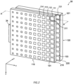
- Fig. 2 is a perspective view schematically showing the reflection apparatus 30.
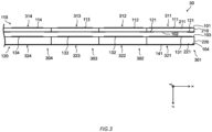
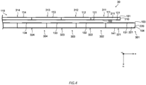
- Figs. 3 and 4 show a part of a cross section of the reflection apparatus 30 taken along line A-A in Fig. 2 .
- Fig. 3 shows a case where relative positions of the first device 110 and the second device 120 included in reflection apparatus 30 are aligned.
- Fig. 4 shows a case where the relative positions of the first device 110 and the second device 120 are not aligned, and the first device 110 is displaced with respect to the second device 120.
- coordinate axes may be shown to describe the configuration of the reflection apparatus 30.
- coordinate axes are shown for the purpose of representing directions.
- An x axis and a y axis of the coordinate axes are set in a plane parallel to a main surface of the reflection apparatus 30.
- a direction in which an incident wave is incident on the reflection apparatus 30 is defined as positive, and a direction in which a reflected wave is emitted is defined as negative.
- the configuration of the reflection apparatus 30 will be described with reference to Figs. 2 to 4 .
- the reflection apparatus 30 reflects radio waves.
- the reflection apparatus 30 includes the first device 110 and the second device 120 provided along an emission direction of a reflected wave, and an adjustment apparatus 34.
- the first device 110 provides an incident surface on which an incident wave, which is a radio wave incident on the reflection apparatus 30, can be directly incident, and an output surface of a reflected wave.
- a radio wave having passed through the first device 110 are incident on the second device 120.
- the first device 110 is located on a negative z-axis side with respect to the second device 120.
- the first device 110 may be a device located closer to the base station 20 than the second device 120.
- the first device 110 has a configuration in which a plurality of elements including a first element 111, a first element 112, a first element 113, and a first element 114 are arranged in a matrix on a first substrate 210.
- the second device 120 has a configuration in which a plurality of elements similar to the first elements are arranged in a matrix on a second substrate 220.
- the first device 110 includes a first unit 311 including a first base body 211 having a first surface 101 and a second surface 102 provided along the emission direction of a reflected wave, the first element 111 provided on the first surface 101, and a second element 121 provided on the second surface 102 to be shifted in position from the first element 111 in the emission direction of the reflected wave.
- the second surface 102 is a surface opposite to the first surface 101.
- the first surface 101 is located on the negative z-axis side with respect to the second surface 102.
- the first device 110 has a configuration in which a plurality of first units having configurations same as or similar to that of the first unit 311 are arranged in a matrix.
- the first units arranged in a direction along the x axis have configurations same as each other except that the sizes of the first elements included in the respective units are different from each other.
- the first element 111 of the first unit 311 is larger than the first element 112 of a first unit 312
- the first element 112 of the first unit 312 is larger than the first element 113 of a first unit 313
- the first element 113 of the first unit 313 is larger than the first element 114 of a first unit 314.
- the first units arranged in a direction along the y axis have configurations same as each other. Accordingly, the wave reflected by the reflection apparatus 30 can have phases different from each other at different positions in an x-axis direction.
- the first device 110 is described as including a configuration in which a plurality of first units are arranged, but the plurality of first units indicate specific parts of the first device 110, and does not mean that the plurality of first units are a plurality of separate members.
- the first base body indicates a specific part of the first substrate 210, and the first substrate 210 may be integrally configured by one member.
- the second device 120 includes a second unit 320 including a second base body 221 having a third surface 103 and a fourth surface 104 provided along the emission direction of a reflected wave, a third element 131 provided on the third surface 103, and a fourth element 141 provided on the fourth surface.
- the fourth surface 104 is a surface opposite to the third surface 103.
- the third surface 103 is located on the negative z-axis side with respect to the fourth surface 104.
- the second surface 102 and the second element 121 are surfaces that can face at least a part of the third surface 103 and the third element 131.
- the second device 120 has a configuration in which a plurality of second units having configurations same as or similar to that of the second unit 321 are arranged in a matrix.
- the second units arranged in the direction along the x axis have configurations same as each other except that the sizes of the third elements included in the respective units are different from each other.
- the third element 131 of the second unit 321 is larger than a third element 132 of a second unit 322
- the third element 132 of the second unit 322 is larger than a third element 133 of a second unit 323
- the third element 133 of the second unit 324 is larger than a first element 134 of a second unit 324.
- the second units arranged in the direction along the y axis have configurations same as each other.
- the second device 120 is described as including a configuration in which a plurality of second units are arranged, but the plurality of second units indicate specific parts of the second device 120, and does not mean that the plurality of second units are a plurality of separate members.
- the second base body indicates a specific part of the second substrate 220, and the second substrate 220 may be integrally configured by one member.
- the first element 111, the second element 121, the third element 131, and the fourth element 141 are conductors.
- the first element 111 and the third element 131 are conductors having a frequency selective surface (FSS).
- the fourth element 141 is a ground conductor and provides a reflecting surface for radio waves. A radio wave incident on the reflection apparatus 30 passes through the first device 110, enters the second device 120, is reflected by the fourth element, passes through the second device 120 and the first device 110, and is emitted as a reflected wave to the outside.
- a phase difference is generated in the radio wave incident on the reflection apparatus 30 by the members constituting the first device 110 and the members constituting the second device 120, and the radio wave is emitted as a reflected wave from the reflection apparatus 30, from the first device 110 to the outside of the reflection apparatus 30.
- the first device 110 is provided separated from the second device 120.
- a relative positional relationship between the first device 110 and the second device 120 in a direction along the second surface 102 is adjustable.
- the second device 120 is fixed, and the first device 110 can be displaced relative to the second device 120 in the direction along the x axis.
- the adjustment apparatus 34 adjusts the relative positional relationship between the first device 110 and the second device 120.
- the adjustment apparatus 34 is attached to the first device 110 and displaces the first device 110 in the direction along the x axis.
- the adjustment apparatus 34 may include a displacement mechanism that displaces a moving member fixed to the first device 110 with an adjustment member such as a screw.
- the phase of the reflected wave is determined by surface areas of the first element 111 and the second element 121, a relative positional relationship between the first element 111 and the second element 121, a thickness of the first base body 211, surface areas of third element 131 and fourth element 141, and a thickness of second base body 221.
- the phase of the reflected wave is further determined by an interval between the second substrate 210 and the second substrate 220, a dielectric constant of the first substrate 210, and a dielectric constant of the second substrate 220.
- the phase of the reflected wave is not electrically determined, but is determined by a mechanical structure of the reflection apparatus 30.
- the plurality of first units included in the first device 110 and the plurality of second device 120 included in the second device 120 are provided such that, for example, a phase difference of the reflected wave varies by a certain amount between the plurality of first units included in the first device 110 in the x-axis direction.
- the wave reflected by reflection apparatus 30 propagates in a specific direction.
- the arrangement of the plurality of first elements and the plurality of second elements 121 included in the first device 110 and a plurality of third elements 131 included in the second device 120 is changed, so that the phase difference of the reflected wave in the x-direction is changed. Accordingly, it is possible to change a direction in which the wave reflected by the reflection apparatus 30 propagates. Therefore, the direction in which the wave reflected by the reflection apparatus 30 propagates can be adjusted by adjusting the relative position of the first device 110 with respect to the second device 120 along the x-axis direction. Accordingly, in a case where the reflection apparatus 30 is installed in the building 90, the direction in which the wave reflected by the reflection apparatus 30 propagates can be adjusted so as to eliminate a coverage hole of the base station 20.
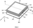
- Fig. 5 is a perspective view of a unit 301 including the first unit 311 and the second unit 321.
- Fig. 6 shows a cross section of the unit 301 taken along line B-B in Fig. 5.
- Figs. 5 and 6 are diagrams in a case where the positions of the first device 110 and the second device 120 are aligned.
- the second elements 121 are located at an end on a positive x-axis side and an end on a negative x-axis side on the second surface 102.
- the second element 121 is located at the center of the second surface 102 in a y-axis direction.
- the second element 121 is provided at a position shifted from the first element 111.
- the range occupied by the first element 111 and the range occupied by the second element 121 do not coincide with each other in the xy plane. That is, the first element 111 and the second element 121 are provided such that a region where the second element 121 does not overlap the first element 111 exists and/or a region where the first element 111 does not overlap the second element 121 exists when viewed in a z-axis direction.
- the shapes of the first base body 211 and the second base body 221 are square.
- the shapes of the first element 111, the second element 121, and the third element 131 are square.
- a length of one side of the first unit 311 is 0.38 ⁇
- a length of one side of the second unit 321 is 0.38 ⁇
- a length of one side of the first base body 211 is 0.38 ⁇
- a length of one side of the second base body 221 is 0.38 ⁇ .
- a thickness d1 of the first base body 211 is 0.03 ⁇ , and a dielectric constant of the first base body 211 is 2.16.
- a thickness d2 of the second base body 221 is 0.06 ⁇ , and a dielectric constant of the second base body 221 is 2.56.
- An interval D between the first base body 211 and the second base body 221 is 0.038 ⁇ .
- a length L1 of one side of the first element 111 is 0.346 ⁇ .
- a length L2 of one side of the second element 121 is 0.11 ⁇ . Since the second element 121 is provided to be shared with the adjacent first unit, a length of the second element 121 in the x-axis direction with respect to the portion occupied by the second element 121 in the second unit is L2/2.
- a thickness of the first element 111 and a thickness of the second element 121 are 0.000346 ⁇ .
- a length L3 of one side of the third element 131 is 0.346 ⁇ .
- a length of one side of the portion occupied by the fourth element 141 in the second unit 321 is 0.38 ⁇ .
- a thickness of the third element 131 and a thickness of the fourth element are 0.000346 ⁇ .
- a phase difference of a reflected wave obtained in a case where the first device 110 is displaced with respect to the second device 120 will be described.
- a frequency of a target radio wave is 5.77 GHz.
- Fig. 7 is a graph showing a phase change amount obtained by displacing the first device 110 with respect to the second device 120.
- a line 700 indicates the phase of the reflected wave in a case where the position of the first device 110 and the position of the second device 120 are aligned.
- phase change amount a difference from the phase indicated by the line 700 may occur.
- phase change amount a phase difference from the phase corresponding to 5.77 GHz on the line 700 is referred to as a "phase change amount”.
- a line 710 indicates the phase of the reflected wave in a case where the first device 110 is displaced with respect to the second device 120 and the second device 120 is fixed at a position where the phase change amount is maximized.
- the phase change amount is 312.7° at the maximum. That is, in the present embodiment, the phase can be adjusted within a range of 312.7°. That is, by displacing the first device 110 with respect to the second device 120, a reflection angle of the reflected wave can be made relatively large.
- Fig. 8 schematically shows a unit 800 included in a reflector in a first comparative example.
- the unit 800 is a unit corresponding to the unit 301 shown in Fig. 6 .
- the unit 800 differs from the unit 301 in that the unit 800 does not have the second element 121, and the first base body 211 is not substantially separated from the second base body 221.
- the position of the first base body 211 with respect to the second base body 221 cannot be displaced after manufacturing.
- Fig. 9 is a graph showing a phase change amount in the first comparative example.
- a line 900 indicates the phase of the reflected wave in a case where the position of the first base body 211 and the position of the second base body 221 are aligned.
- a line 910 indicates the phase of the reflected wave in a case where the position of the first base body 211 is set with respect to the second base body 221 such that the phase change amount is maximized at 5.77 GHz.
- the phase change amount is 315.9°.
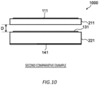
- Fig. 10 schematically shows a unit 1000 included in a reflector in the second comparative example.
- the unit 1000 is a unit corresponding to the unit 301 shown in Fig. 6 .
- the unit 1000 differs from the unit 301 in that the unit 1000 does not have the second element 121.
- the position of the first base body 211 with respect to the second base body 221 can be displaced after manufacturing.
- Fig. 11 is a graph showing a phase change amount in the second comparative example.
- a line 1100 indicates the phase of the reflected wave in a case where the position of the first base body 211 and the position of the second base body 221 are aligned.
- a line 1110 indicates the phase of the reflected wave in a case where the position of the first base body 211 is displaced with respect to the second base body 221 such that the phase change amount is maximized at 5.77 GHz.
- the phase change amount is 208.5°.
- the first base body 211 and the second base body 221 are separated from each other, so that the position of the first base body 211 can be displaced with respect to the second base body 221.
- the phase change amount decreases from 315.9° to 208.5°. That is, a range of a settable reflection angle is narrowed.
- the phase change amount can be greatly expanded to 312.7° by providing the second element 121. That is, according to the reflection apparatus 30 described above, the first device 110 and the second device 120 are separated from each other, so that the first device 110 is allowed to be displaceable with respect to the second device 120 to allow the phase of the reflected wave to be adjustable, and it is possible to obtain the phase change amount equivalent to the phase change amount 315.9° obtained by the first comparative example.
- a length of one side of the plurality of first units included in the first device 110 is 0.38 ⁇ , where ⁇ is a wavelength of a radio wave incident on the reflection apparatus 30.
- the length of one side of the first unit is not limited to this value, and an arbitrary value of a length of 0.3 ⁇ or more and 0.6 ⁇ or less can be applied as the length of one side of each of the plurality of first units included in the first device 110, where ⁇ is a wavelength of a radio wave incident on the reflection apparatus 30.
- the shapes of the plurality of first elements including the first element 111, the plurality of second elements including the second element 122, and the plurality of third elements including the third element 131 are square.
- the shapes of the first element, the second element, and the third element are not limited to being square.
- the first element, the second element, and the third element may have a polygonal shape or a shape curved at least in part.
- a plurality of first base bodies including the first base body 211 and a plurality of second base bodies including the second base body 221 are square.
- the shapes of the first base body and the second base body are not limited to being square.
- the first base body and the second base body may have a polygonal shape or a shape curved at least in part.
- the plurality of first elements including the first element 111 may transmit a specific linearly polarized wave or a specific circularly polarized wave.
- the plurality of second elements including the second element 122 may transmit a specific linearly polarized wave or a specific circularly polarized wave.
- the base station 20 is an example of a radio wave radiation apparatus that radiates a radio wave incident on the reflection apparatus 30.
- a reflection apparatus having the configuration included in the reflection apparatus 30 can be applied as a reflection apparatus that reflects a radio wave radiated from a radio wave radiation apparatus other than the base station 20 for mobile communication described above.
- 10 system; 20: base station; 30: reflection apparatus; 34: adjustment apparatus; 101: first surface; 102: second surface; 103: third surface; 104: fourth surface; 110: first device; 120: second device; 111, 112, 113, 114: first element; 121: second element; 131: third element; 141: fourth element; 101: first surface; 102: second surface; 103: third surface; 104: fourth surface; 211: first base body; 221: second base body; 311: first unit; 321: second unit.
Landscapes
- Physics & Mathematics (AREA)
- Electromagnetism (AREA)
- Aerials With Secondary Devices (AREA)
Abstract
Description
- The present invention relates to a reflection apparatus and a system.
- In
Patent Document 1, a reflector array in which a large number of elements as small as a wavelength are arranged in a planar shape is described as a reflector that reflects radio waves. - Patent Document 1:
Japanese Patent Application Publication No. 2015-46821 - According to an embodiment of the present invention, a reflection apparatus is provided. The reflection apparatus reflects a radio wave. The reflection apparatus includes a first device and a second device which are provided along an emission direction of a reflected wave. The first device includes a plurality of first units each including a first base body which has a first surface and a second surface provided along the emission direction of the reflected wave, a first element which is provided on the first surface, and a second element which is provided on the second surface to be shifted in position from the first element in the emission direction of the reflected wave. The second device includes a plurality of second units each including a second base body which has a third surface and a fourth surface provided along the emission direction of the reflected wave, a third element which is provided on the third surface, and a fourth element which is provided on the fourth surface. The first device is provided separated from the second device, and a relative positional relationship between the first device and the second device in a direction along the second surface is adjustable.
- In the reflection apparatus, a phase of the reflected wave may be determined by surface areas of the first element and the second element, a relative positional relationship between the first element and the second element, a thickness of the first base body, surface areas of the third element and the fourth element, and a thickness of the second base body.
- In any of the reflection apparatuses, the plurality of first units and the plurality of second units may be provided at a plurality of positions along a specific direction along the first surface, such that phases of the reflected wave are different from each other.
- In any of the reflection apparatuses, the plurality of first units and the plurality of second units may be provided such that the reflected wave propagates in a specific direction.
- Any of the reflection apparatuses may further include an adjustment apparatus which adjusts a relative positional relationship between the first device and the second device.
- In any of the reflection apparatuses, a length of one side of each of the plurality of first units may be 0.3λ or more and 0.6λ or less where λ is a wavelength of a radio wave incident on the reflection apparatus.
- In any of the reflection apparatuses, the first element, the second element, and the third element each may have a polygonal shape or a shape curved at least in part.
- In any of the reflection apparatuses, the first element may transmit a specific linearly polarized wave or a specific circularly polarized wave.
- In any of the reflection apparatuses, the first base body and the second base body each may have a polygonal shape or a shape curved at least in part.
- In any of the reflection apparatuses, the first element and the third element may be conductors having a frequency selective surface (FSS).
- According to an embodiment of the present invention, a system is provided. The system includes any of the reflection apparatuses. The system includes a radio wave radiation apparatus which radiates a radio wave incident on the reflection apparatus.
- The summary clause does not necessarily describe all necessary features of the embodiments of the present invention. The present invention may also be a sub-combination of the features described above.
-
-
Fig. 1 schematically shows an example of a configuration of asystem 10 including areflection apparatus 30. -
Fig. 2 is a perspective view schematically showing thereflection apparatus 30. -
Fig. 3 shows a case where relative positions of afirst device 110 and asecond device 120 included in thereflection apparatus 30 are aligned. -
Fig. 4 shows a part of a cross section of thereflection apparatus 30 taken along line A-A inFig. 2 . -
Fig. 5 is a perspective view of aunit 301 including afirst unit 311 and asecond unit 321. -
Fig. 6 shows a cross section of theunit 301 taken along line B-B inFig. 5 . -
Fig. 7 is a graph showing a phase change amount obtained by displacing thefirst device 110 with respect to thesecond device 120. -
Fig. 8 schematically shows aunit 800 included in a reflector in a first comparative example. -
Fig. 9 is a graph showing a phase change amount in the first comparative example. -
Fig. 10 schematically shows aunit 1000 included in a reflector in a second comparative example. -
Fig. 11 is a graph showing a phase change amount in the second comparative example. - For example, in a 5th generation mobile communication system, radio waves in a relatively high frequency band are used. Since radio waves in a high frequency band have high straightness, it is difficult for the radio waves to diffract around an obstacle such as a building to reach a shadow zone. For this reason, many coverage holes (areas in which communication cannot be performed) are generated in an area that is invisible from a base station, and a communication coverage area may be narrowed. Therefore, in order to expand the communication coverage area, it is necessary to install a large number of base stations. Accordingly, a cost for expanding the communication area increases.
- A reflector is provided in a construction such as a building, and a radio wave radiated from a base station is reflected by the reflector, so that the radio wave can reach an area which is the shadow zone of the obstacle. As the reflector for this purpose, a meta-surface reflector capable of making an incident angle and a reflection angle of a radio wave different has been studied.
- In order to effectively reduce the coverage holes, it is desirable that the phase of the reflected wave is adjustable in order to adjust the reflection angle. As the meta-surface reflector capable of adjusting the phase of the reflected wave, a configuration using a material having a variable dielectric constant (for example, liquid crystal or the like), a configuration in which a plurality of varactor diodes or PIN diodes are arranged in each cell for adjusting impedance, and the like are considered. However, in these configurations, power is required to maintain the reflection angle in a specific direction. In the configuration using diodes or PIN diodes, a cell structure becomes complicated, and the manufacturing cost of the reflector increases.
- On the other hand, in the
system 10 including thereflection apparatus 30 according to the present embodiment, thereflection apparatus 30 has a structure in which thefirst device 110 and thesecond device 120 are separated from each other. This allows for adjusting the relative in-plane positions of thefirst device 110 and thesecond device 120, thereby enabling the adjustment of the phase of the reflected wave. Accordingly, the manufacturing cost of thereflection apparatus 30 is reduced, while power for maintaining the reflection angle of the radio wave in a specific direction becomes substantially unnecessary. Furthermore, in thereflection apparatus 30, an additional element is provided between the first device 100 and the second device 200, thereby enabling the expansion of the phase change amount of the reflected wave in an operation frequency band. Accordingly, it becomes possible to expand a communication coverage area through a base station. Therefore, the number of base stations can be suppressed, so that the cost for expanding the communication coverage area can be reduced. - Hereinafter, the present invention will be described through embodiments of the invention, but the following embodiments do not limit the invention according to the claims. In addition, not all of the combinations of features described in the embodiments are essential to the solution of the invention.
-
Fig. 1 schematically shows an example of a configuration of thesystem 10 including thereflection apparatus 30. Thesystem 10 includes abase station 20 and thereflection apparatus 30. In the present embodiment, thesystem 10 is a mobile communication system. Thebase station 20 radiates radio waves for mobile communication. - The radio waves radiated by the
base station 20 include a radio wave in a frequency band that can be used in the 5th generation mobile communication system. Specifically, the radio waves radiated by thebase station 20 may include a radio wave in a frequency band equal to or higher than the frequency band of the S-band. The radio waves radiated by thebase station 20 may include a radio wave in a frequency band equal to or higher than the frequency band of the C-band. The radio waves radiated by thebase station 20 may include a radio wave in submillimeter to millimeter wave bands. In the present embodiment, the radio waves radiated by thebase station 20 include, for example, a radio wave of 5.77 GHz. - For example, the radio wave in the frequency band equal to or higher than the frequency band of the S-band is less likely to diffract around an obstacle such as a building to reach a shadow zone than a radio wave in a frequency band (for example, a 700 MHz band and an 800 MHz band) equal to or lower than the frequency band of the L-band. An
area 80 is located in a shadow zone of abuilding 90 as viewed from thebase station 20. For this reason, the strength of a radio wave radiated from thebase station 20 and directly reaching thearea 80 becomes significantly weak. - The
reflection apparatus 30 reflects the radio wave radiated from thebase station 20. Thereflection apparatus 30 is provided, for example, on a wall surface of abuilding 92 located in a line-of-sight range of thebase station 20. Thereflection apparatus 30 reflects an incident radio wave in a specific direction. Thereflection apparatus 30 is configured to be able to adjust a direction in which thereflection apparatus 30 reflects a radio wave. Thereflection apparatus 30 is adjusted such that the radio wave radiated from thebase station 20 and incident on thereflection apparatus 30 is reflected by thereflection apparatus 30 and travels toward thearea 80. Thereflection apparatus 30 enables the radio wave radiated from thebase station 20 to reach thearea 80. Accordingly, it is possible to expand the communication coverage area through thebase station 20 without adding a base station. Therefore, the cost for expanding the communication coverage area can be reduced. -
Fig. 2 is a perspective view schematically showing thereflection apparatus 30.Figs. 3 and4 show a part of a cross section of thereflection apparatus 30 taken along line A-A inFig. 2 .Fig. 3 shows a case where relative positions of thefirst device 110 and thesecond device 120 included inreflection apparatus 30 are aligned.Fig. 4 shows a case where the relative positions of thefirst device 110 and thesecond device 120 are not aligned, and thefirst device 110 is displaced with respect to thesecond device 120. - In the drawings of the present embodiment, coordinate axes may be shown to describe the configuration of the
reflection apparatus 30. In the drawings of the present embodiment, coordinate axes are shown for the purpose of representing directions. An x axis and a y axis of the coordinate axes are set in a plane parallel to a main surface of thereflection apparatus 30. In the direction of a z axis of the coordinate axes, generally, a direction in which an incident wave is incident on thereflection apparatus 30 is defined as positive, and a direction in which a reflected wave is emitted is defined as negative. - The configuration of the
reflection apparatus 30 will be described with reference toFigs. 2 to 4 . Thereflection apparatus 30 reflects radio waves. Thereflection apparatus 30 includes thefirst device 110 and thesecond device 120 provided along an emission direction of a reflected wave, and anadjustment apparatus 34. - The
first device 110 provides an incident surface on which an incident wave, which is a radio wave incident on thereflection apparatus 30, can be directly incident, and an output surface of a reflected wave. A radio wave having passed through thefirst device 110 are incident on thesecond device 120. Thefirst device 110 is located on a negative z-axis side with respect to thesecond device 120. Thefirst device 110 may be a device located closer to thebase station 20 than thesecond device 120. - The
first device 110 has a configuration in which a plurality of elements including afirst element 111, afirst element 112, afirst element 113, and afirst element 114 are arranged in a matrix on afirst substrate 210. Similarly, thesecond device 120 has a configuration in which a plurality of elements similar to the first elements are arranged in a matrix on asecond substrate 220. - The
first device 110 includes afirst unit 311 including afirst base body 211 having afirst surface 101 and asecond surface 102 provided along the emission direction of a reflected wave, thefirst element 111 provided on thefirst surface 101, and asecond element 121 provided on thesecond surface 102 to be shifted in position from thefirst element 111 in the emission direction of the reflected wave. - The
second surface 102 is a surface opposite to thefirst surface 101. Thefirst surface 101 is located on the negative z-axis side with respect to thesecond surface 102. - As shown in
Fig. 2 , thefirst device 110 has a configuration in which a plurality of first units having configurations same as or similar to that of thefirst unit 311 are arranged in a matrix. - Specifically, in the
first device 110, the first units arranged in a direction along the x axis have configurations same as each other except that the sizes of the first elements included in the respective units are different from each other. For example, as shown inFigs. 2 and3 or the like, thefirst element 111 of thefirst unit 311 is larger than thefirst element 112 of afirst unit 312, thefirst element 112 of thefirst unit 312 is larger than thefirst element 113 of afirst unit 313, and thefirst element 113 of thefirst unit 313 is larger than thefirst element 114 of afirst unit 314. On the other hand, the first units arranged in a direction along the y axis have configurations same as each other. Accordingly, the wave reflected by thereflection apparatus 30 can have phases different from each other at different positions in an x-axis direction. - For convenience of description, the
first device 110 is described as including a configuration in which a plurality of first units are arranged, but the plurality of first units indicate specific parts of thefirst device 110, and does not mean that the plurality of first units are a plurality of separate members. Similarly, the first base body indicates a specific part of thefirst substrate 210, and thefirst substrate 210 may be integrally configured by one member. - The
second device 120 includes a second unit 320 including asecond base body 221 having athird surface 103 and afourth surface 104 provided along the emission direction of a reflected wave, athird element 131 provided on thethird surface 103, and afourth element 141 provided on the fourth surface. - The
fourth surface 104 is a surface opposite to thethird surface 103. Thethird surface 103 is located on the negative z-axis side with respect to thefourth surface 104. Thesecond surface 102 and thesecond element 121 are surfaces that can face at least a part of thethird surface 103 and thethird element 131. - Similarly to the
first device 110, thesecond device 120 has a configuration in which a plurality of second units having configurations same as or similar to that of thesecond unit 321 are arranged in a matrix. - Specifically, in the
second device 120, the second units arranged in the direction along the x axis have configurations same as each other except that the sizes of the third elements included in the respective units are different from each other. For example, as shown inFig. 3 or the like, thethird element 131 of thesecond unit 321 is larger than athird element 132 of asecond unit 322, thethird element 132 of thesecond unit 322 is larger than athird element 133 of asecond unit 323, and thethird element 133 of thesecond unit 324 is larger than afirst element 134 of asecond unit 324. On the other hand, the second units arranged in the direction along the y axis have configurations same as each other. - For convenience of description, the
second device 120 is described as including a configuration in which a plurality of second units are arranged, but the plurality of second units indicate specific parts of thesecond device 120, and does not mean that the plurality of second units are a plurality of separate members. Similarly, the second base body indicates a specific part of thesecond substrate 220, and thesecond substrate 220 may be integrally configured by one member. - The
first element 111, thesecond element 121, thethird element 131, and thefourth element 141 are conductors. As an example, thefirst element 111 and thethird element 131 are conductors having a frequency selective surface (FSS). Thefourth element 141 is a ground conductor and provides a reflecting surface for radio waves. A radio wave incident on thereflection apparatus 30 passes through thefirst device 110, enters thesecond device 120, is reflected by the fourth element, passes through thesecond device 120 and thefirst device 110, and is emitted as a reflected wave to the outside. A phase difference is generated in the radio wave incident on thereflection apparatus 30 by the members constituting thefirst device 110 and the members constituting thesecond device 120, and the radio wave is emitted as a reflected wave from thereflection apparatus 30, from thefirst device 110 to the outside of thereflection apparatus 30. - The
first device 110 is provided separated from thesecond device 120. A relative positional relationship between thefirst device 110 and thesecond device 120 in a direction along thesecond surface 102 is adjustable. Specifically, thesecond device 120 is fixed, and thefirst device 110 can be displaced relative to thesecond device 120 in the direction along the x axis. - The
adjustment apparatus 34 adjusts the relative positional relationship between thefirst device 110 and thesecond device 120. For example, theadjustment apparatus 34 is attached to thefirst device 110 and displaces thefirst device 110 in the direction along the x axis. Theadjustment apparatus 34 may include a displacement mechanism that displaces a moving member fixed to thefirst device 110 with an adjustment member such as a screw. - The phase of the reflected wave is determined by surface areas of the
first element 111 and thesecond element 121, a relative positional relationship between thefirst element 111 and thesecond element 121, a thickness of thefirst base body 211, surface areas ofthird element 131 andfourth element 141, and a thickness ofsecond base body 221. The phase of the reflected wave is further determined by an interval between thesecond substrate 210 and thesecond substrate 220, a dielectric constant of thefirst substrate 210, and a dielectric constant of thesecond substrate 220. As described above, the phase of the reflected wave is not electrically determined, but is determined by a mechanical structure of thereflection apparatus 30. - The plurality of first units included in the
first device 110 and the plurality of second units included in thesecond device 120 are provided at a plurality of positions along a specific direction along thefirst surface 101, such that the phases of the reflected wave are different from each other. Specifically, the plurality of first units and the plurality of second units are provided such that the reflected wave propagates in a specific direction. - The plurality of first units included in the
first device 110 and the plurality ofsecond device 120 included in thesecond device 120 are provided such that, for example, a phase difference of the reflected wave varies by a certain amount between the plurality of first units included in thefirst device 110 in the x-axis direction. In this case, the wave reflected byreflection apparatus 30 propagates in a specific direction. - By changing a relative position of the
first device 110 with respect to thesecond device 120 along the x-axis direction, the arrangement of the plurality of first elements and the plurality ofsecond elements 121 included in thefirst device 110 and a plurality ofthird elements 131 included in thesecond device 120 is changed, so that the phase difference of the reflected wave in the x-direction is changed. Accordingly, it is possible to change a direction in which the wave reflected by thereflection apparatus 30 propagates. Therefore, the direction in which the wave reflected by thereflection apparatus 30 propagates can be adjusted by adjusting the relative position of thefirst device 110 with respect to thesecond device 120 along the x-axis direction. Accordingly, in a case where thereflection apparatus 30 is installed in thebuilding 90, the direction in which the wave reflected by thereflection apparatus 30 propagates can be adjusted so as to eliminate a coverage hole of thebase station 20. - An example of a specific structure of the
first unit 311 and thesecond unit 321 will be described with reference toFigs. 5 and6 .Fig. 5 is a perspective view of aunit 301 including thefirst unit 311 and thesecond unit 321.Fig. 6 shows a cross section of theunit 301 taken along line B-B inFig. 5. Figs. 5 and6 are diagrams in a case where the positions of thefirst device 110 and thesecond device 120 are aligned. - As shown in
Fig. 6 , in theunit 301, thesecond elements 121 are located at an end on a positive x-axis side and an end on a negative x-axis side on thesecond surface 102. Thesecond element 121 is located at the center of thesecond surface 102 in a y-axis direction. - In this manner, the
second element 121 is provided at a position shifted from thefirst element 111. For example, in a case where thefirst element 111 and thesecond element 121 are projected on an xy plane, the range occupied by thefirst element 111 and the range occupied by thesecond element 121 do not coincide with each other in the xy plane. That is, thefirst element 111 and thesecond element 121 are provided such that a region where thesecond element 121 does not overlap thefirst element 111 exists and/or a region where thefirst element 111 does not overlap thesecond element 121 exists when viewed in a z-axis direction. - In the present embodiment, when viewed in the z-axis direction, the shapes of the
first base body 211 and thesecond base body 221 are square. When viewed in the z-axis direction, the shapes of thefirst element 111, thesecond element 121, and thethird element 131 are square. - Assuming that a wavelength of a radio wave incident on the
reflection apparatus 30 is λ, a length of one side of thefirst unit 311 is 0.38λ, and a length of one side of thesecond unit 321 is 0.38λ. Specifically, a length of one side of thefirst base body 211 is 0.38λ, and a length of one side of thesecond base body 221 is 0.38λ. - A thickness d1 of the
first base body 211 is 0.03λ, and a dielectric constant of thefirst base body 211 is 2.16. A thickness d2 of thesecond base body 221 is 0.06λ, and a dielectric constant of thesecond base body 221 is 2.56. An interval D between thefirst base body 211 and thesecond base body 221 is 0.038λ. - A length L1 of one side of the
first element 111 is 0.346λ. A length L2 of one side of thesecond element 121 is 0.11λ. Since thesecond element 121 is provided to be shared with the adjacent first unit, a length of thesecond element 121 in the x-axis direction with respect to the portion occupied by thesecond element 121 in the second unit is L2/2. A thickness of thefirst element 111 and a thickness of thesecond element 121 are 0.000346λ. - A length L3 of one side of the
third element 131 is 0.346λ. A length of one side of the portion occupied by thefourth element 141 in thesecond unit 321 is 0.38λ. A thickness of thethird element 131 and a thickness of the fourth element are 0.000346λ. - With reference to
Fig. 7 , a phase difference of a reflected wave obtained in a case where thefirst device 110 is displaced with respect to thesecond device 120 will be described. Here, it is assumed that a frequency of a target radio wave is 5.77 GHz. -
Fig. 7 is a graph showing a phase change amount obtained by displacing thefirst device 110 with respect to thesecond device 120. Aline 700 indicates the phase of the reflected wave in a case where the position of thefirst device 110 and the position of thesecond device 120 are aligned. - When the
first device 110 is displaced with respect to thesecond device 120, a difference (phase change amount) from the phase indicated by theline 700 may occur. Here, a phase difference from the phase corresponding to 5.77 GHz on theline 700 is referred to as a "phase change amount". Aline 710 indicates the phase of the reflected wave in a case where thefirst device 110 is displaced with respect to thesecond device 120 and thesecond device 120 is fixed at a position where the phase change amount is maximized. - As shown in
Fig. 7 , in the present embodiment, the phase change amount is 312.7° at the maximum. That is, in the present embodiment, the phase can be adjusted within a range of 312.7°. That is, by displacing thefirst device 110 with respect to thesecond device 120, a reflection angle of the reflected wave can be made relatively large. -
Fig. 8 schematically shows aunit 800 included in a reflector in a first comparative example. Theunit 800 is a unit corresponding to theunit 301 shown inFig. 6 . Theunit 800 differs from theunit 301 in that theunit 800 does not have thesecond element 121, and thefirst base body 211 is not substantially separated from thesecond base body 221. In the first comparative example, the position of thefirst base body 211 with respect to thesecond base body 221 cannot be displaced after manufacturing. -
Fig. 9 is a graph showing a phase change amount in the first comparative example. As shown inFig. 8 , aline 900 indicates the phase of the reflected wave in a case where the position of thefirst base body 211 and the position of thesecond base body 221 are aligned. Aline 910 indicates the phase of the reflected wave in a case where the position of thefirst base body 211 is set with respect to thesecond base body 221 such that the phase change amount is maximized at 5.77 GHz. As shown inFig. 9 , according to the configuration of the first comparative example, the phase change amount is 315.9°. -
Fig. 10 schematically shows aunit 1000 included in a reflector in the second comparative example. Theunit 1000 is a unit corresponding to theunit 301 shown inFig. 6 . Theunit 1000 differs from theunit 301 in that theunit 1000 does not have thesecond element 121. According to the second comparative example, unlike the first comparative example, the position of thefirst base body 211 with respect to thesecond base body 221 can be displaced after manufacturing. -
Fig. 11 is a graph showing a phase change amount in the second comparative example. As shown inFig. 10 , aline 1100 indicates the phase of the reflected wave in a case where the position of thefirst base body 211 and the position of thesecond base body 221 are aligned. Aline 1110 indicates the phase of the reflected wave in a case where the position of thefirst base body 211 is displaced with respect to thesecond base body 221 such that the phase change amount is maximized at 5.77 GHz. As shown inFig. 11 , according to the configuration of the second comparative example, the phase change amount is 208.5°. - As can be seen from the comparison between the second comparative example and the first comparative example, the
first base body 211 and thesecond base body 221 are separated from each other, so that the position of thefirst base body 211 can be displaced with respect to thesecond base body 221. However, the phase change amount decreases from 315.9° to 208.5°. That is, a range of a settable reflection angle is narrowed. - As can be seen from the comparison between the second comparative example and the
reflection apparatus 30 described above, the phase change amount can be greatly expanded to 312.7° by providing thesecond element 121. That is, according to thereflection apparatus 30 described above, thefirst device 110 and thesecond device 120 are separated from each other, so that thefirst device 110 is allowed to be displaceable with respect to thesecond device 120 to allow the phase of the reflected wave to be adjustable, and it is possible to obtain the phase change amount equivalent to the phase change amount 315.9° obtained by the first comparative example. - Next, a modification of the
reflection apparatus 30 described above will be described. In thereflection apparatus 30 described above, a length of one side of the plurality of first units included in thefirst device 110 is 0.38λ, where λ is a wavelength of a radio wave incident on thereflection apparatus 30. However, the length of one side of the first unit is not limited to this value, and an arbitrary value of a length of 0.3λ or more and 0.6λ or less can be applied as the length of one side of each of the plurality of first units included in thefirst device 110, where λ is a wavelength of a radio wave incident on thereflection apparatus 30. - In the
reflection apparatus 30 described above, the shapes of the plurality of first elements including thefirst element 111, the plurality of second elements including the second element 122, and the plurality of third elements including thethird element 131 are square. However, the shapes of the first element, the second element, and the third element are not limited to being square. The first element, the second element, and the third element may have a polygonal shape or a shape curved at least in part. - In the
reflection apparatus 30 described above, a plurality of first base bodies including thefirst base body 211 and a plurality of second base bodies including thesecond base body 221 are square. However, the shapes of the first base body and the second base body are not limited to being square. The first base body and the second base body may have a polygonal shape or a shape curved at least in part. - In the
reflection apparatus 30 described above, the plurality of first elements including thefirst element 111 may transmit a specific linearly polarized wave or a specific circularly polarized wave. The plurality of second elements including the second element 122 may transmit a specific linearly polarized wave or a specific circularly polarized wave. - In the
system 10 described above, thebase station 20 is an example of a radio wave radiation apparatus that radiates a radio wave incident on thereflection apparatus 30. A reflection apparatus having the configuration included in thereflection apparatus 30 can be applied as a reflection apparatus that reflects a radio wave radiated from a radio wave radiation apparatus other than thebase station 20 for mobile communication described above. - While the present invention has been described by way of the embodiments, the technical scope of the present invention is not limited to the scope described in the above-described embodiments. It is apparent to persons skilled in the art that various alterations or improvements can be added to the above-described embodiments. It is also apparent from the scope of the claims that the embodiments added with such alterations or improvements can be included in the technical scope of the invention.
- The operations, procedures, steps, and stages of each process executed by a device, system, program, and method shown in the claims, embodiments, or diagrams can be achieved in any order as long as the order is not indicated by "prior to," "before," or the like and as long as the output from a previous process is not used in a later process. Even if the process flow is described using phrases such as "first" or "next" in the claims, embodiments, or diagrams, it does not necessarily mean that the process must be executed in this order.
- 10: system; 20: base station; 30: reflection apparatus; 34: adjustment apparatus; 101: first surface; 102: second surface; 103: third surface; 104: fourth surface; 110: first device; 120: second device; 111, 112, 113, 114: first element; 121: second element; 131: third element; 141: fourth element; 101: first surface; 102: second surface; 103: third surface; 104: fourth surface; 211: first base body; 221: second base body; 311: first unit; 321: second unit.
Claims (11)
- A reflection apparatus which reflects a radio wave, comprisinga first device and a second device which are provided along an emission direction of a reflected wave, whereinthe first device includesa plurality of first units each includinga first base body which has a first surface and a second surface provided along the emission direction of the reflected wave,a first element which is provided on the first surface, anda second element which is provided on the second surface to be shifted in position from the first element in the emission direction of the reflected wave,the second device includesa plurality of second units each includinga second base body which has a third surface and a fourth surface provided along the emission direction of the reflected wave,a third element which is provided on the third surface, anda fourth element which is provided on the fourth surface, andthe first device is provided separated from the second device, and a relative positional relationship between the first device and the second device in a direction along the second surface is adjustable.
- The reflection apparatus according to claim 1, whereina phase of the reflected wave is determined bysurface areas of the first element and the second element,a relative positional relationship between the first element and the second element,a thickness of the first base body,surface areas of the third element and the fourth element, anda thickness of the second base body.
- The reflection apparatus according to claim 1 or 2, wherein
the plurality of first units and the plurality of second units are provided at a plurality of positions along a specific direction along the first surface, such that phases of the reflected wave are different from each other. - The reflection apparatus according to any one of claims 1 to 3, wherein
the plurality of first units and the plurality of second units are provided such that the reflected wave propagates in a specific direction. - The reflection apparatus according to any one of claims 1 to 4, further comprising
an adjustment apparatus which adjusts a relative positional relationship between the first device and the second device. - The reflection apparatus according to any one of claims 1 to 5, wherein
a length of one side of each of the plurality of first units is 0.3λ or more and 0.6λ or less where λ is a wavelength of a radio wave incident on the reflection apparatus. - The reflection apparatus according to any one of claims 1 to 6, wherein
the first element, the second element, and the third element each have a polygonal shape or a shape curved at least in part. - The reflection apparatus according to any one of claims 1 to 7, wherein
the first element transmits a specific linearly polarized wave or a specific circularly polarized wave. - The reflection apparatus according to any one of claims 1 to 8, wherein
the first base body and the second base body each have a polygonal shape or a shape curved at least in part. - The reflection apparatus according to any one of claims 1 to 9, wherein
the first element and the third element are conductors having a frequency selective surface (FSS). - A system comprising:the reflection apparatus according to any one of claims 1 to 10; anda radio wave radiation apparatus which radiates a radio wave incident on the reflection apparatus.
Applications Claiming Priority (2)
| Application Number | Priority Date | Filing Date | Title |
|---|---|---|---|
| JP2022133725A JP7295316B1 (en) | 2022-08-25 | 2022-08-25 | Reflective device and system |
| PCT/JP2023/029607 WO2024043155A1 (en) | 2022-08-25 | 2023-08-16 | Reflection device and system |
Publications (3)
| Publication Number | Publication Date |
|---|---|
| EP4568017A1 true EP4568017A1 (en) | 2025-06-11 |
| EP4568017A4 EP4568017A4 (en) | 2025-11-19 |
| EP4568017B1 EP4568017B1 (en) | 2026-05-06 |
Family
ID=86772631
Family Applications (1)
| Application Number | Title | Priority Date | Filing Date |
|---|---|---|---|
| EP23857268.9A Active EP4568017B1 (en) | 2022-08-25 | 2023-08-16 | Reflection device and system |
Country Status (4)
| Country | Link |
|---|---|
| US (1) | US12401133B2 (en) |
| EP (1) | EP4568017B1 (en) |
| JP (1) | JP7295316B1 (en) |
| WO (1) | WO2024043155A1 (en) |
Families Citing this family (2)
| Publication number | Priority date | Publication date | Assignee | Title |
|---|---|---|---|---|
| WO2025004860A1 (en) * | 2023-06-26 | 2025-01-02 | 京セラ株式会社 | Composite resonator and radio wave control plate |
| JP7773671B1 (en) * | 2025-06-27 | 2025-11-19 | ソフトバンク株式会社 | Reflection devices and systems |
Family Cites Families (13)
| Publication number | Priority date | Publication date | Assignee | Title |
|---|---|---|---|---|
| GB9019628D0 (en) * | 1990-09-07 | 1992-04-08 | Univ Loughborough | Reconfigurable frequency selective surface |
| US6812903B1 (en) * | 2000-03-14 | 2004-11-02 | Hrl Laboratories, Llc | Radio frequency aperture |
| US6483480B1 (en) * | 2000-03-29 | 2002-11-19 | Hrl Laboratories, Llc | Tunable impedance surface |
| JP5355472B2 (en) * | 2009-12-10 | 2013-11-27 | ニッタ株式会社 | Information storage medium, managed article and management system |
| US8988759B2 (en) * | 2010-07-26 | 2015-03-24 | The Invention Science Fund I Llc | Metamaterial surfaces |
| JP6073203B2 (en) | 2013-08-29 | 2017-02-01 | 株式会社Nttドコモ | Reflect array design method |
| EP3442079B1 (en) * | 2016-04-08 | 2020-11-25 | Mitsubishi Electric Corporation | Resonant element for frequency selective plate, frequency selective plate and antenna device |
| US11303020B2 (en) * | 2018-07-23 | 2022-04-12 | Metawave Corporation | High gain relay antenna system with multiple passive reflect arrays |
| CN110854538B (en) | 2019-10-21 | 2021-03-19 | 南京星隐科技发展有限公司 | Microwave metamaterial |
| WO2021106093A1 (en) * | 2019-11-27 | 2021-06-03 | 三菱電機株式会社 | Reflector antenna device |
| JP7284731B2 (en) | 2020-03-27 | 2023-05-31 | 株式会社Nttドコモ | Terminal and communication method |
| JP7500323B2 (en) * | 2020-07-30 | 2024-06-17 | 株式会社ジャパンディスプレイ | Phased array antenna driving method and reflector driving method |
| CN117716637A (en) | 2021-06-01 | 2024-03-15 | 索尼集团公司 | Reconfigurable device for influencing the spatial properties of radio waves |
-
2022
- 2022-08-25 JP JP2022133725A patent/JP7295316B1/en active Active
-
2023
- 2023-08-16 WO PCT/JP2023/029607 patent/WO2024043155A1/en not_active Ceased
- 2023-08-16 EP EP23857268.9A patent/EP4568017B1/en active Active
-
2025
- 2025-02-11 US US19/051,152 patent/US12401133B2/en active Active
Also Published As
| Publication number | Publication date |
|---|---|
| EP4568017B1 (en) | 2026-05-06 |
| US12401133B2 (en) | 2025-08-26 |
| JP2024030681A (en) | 2024-03-07 |
| JP7295316B1 (en) | 2023-06-20 |
| WO2024043155A1 (en) | 2024-02-29 |
| US20250183546A1 (en) | 2025-06-05 |
| EP4568017A4 (en) | 2025-11-19 |
Similar Documents
| Publication | Publication Date | Title |
|---|---|---|
| US12401133B2 (en) | Reflection apparatus and system | |
| US9054414B2 (en) | Antenna system for low-earth-orbit satellites | |
| EP3005481B1 (en) | Lens antenna | |
| US7034753B1 (en) | Multi-band wide-angle scan phased array antenna with novel grating lobe suppression | |
| Yang et al. | A linearly-polarized-feed dual-circularly polarized dual-beam transmitarray with independent beam control | |
| EP2884584B1 (en) | Selectable low-gain/high-gain beam implementation for victs antenna arrays | |
| US12283750B2 (en) | Low profile multi band antenna system | |
| Nisamol et al. | Design of sub-THz slotted waveguide array antenna for the broadside circularly polarized applications beyond 5G | |
| Honari et al. | A dual-band transmitarray antenna employing ultra-thin, polarization-rotating spatial phase shifters | |
| Kawahara et al. | Design of rotational dielectric dome with linear array feed for wide‐angle multibeam antenna applications | |
| WO2019170541A1 (en) | Extreme scanning focal-plane arrays using a double-reflector concept with uniform array illumination | |
| EP4229719A1 (en) | Reflectarray and method therefor | |
| Nisamol et al. | Design of sub-THz beam scanning antenna using Luneburg lens for 5G communications or beyond | |
| Boccia et al. | Antenna basics | |
| US10797401B2 (en) | Reflection mirror antenna device | |
| Jasim et al. | Low-Profile Leaky-Wave Antenna with Mechanical Beam Steering Using Sliding Slot Arrays for K-Band Communications | |
| Goudarzi et al. | A cylindrical coaxial-fed resonant cavity antenna with off-axis beaming for 5G applications | |
| Hirokawa et al. | Postwall waveguide slot array with cosecant radiation pattern and null filling for base station antennas in local multidistributed systems | |
| Yang et al. | Recent advances in beam-scanning reflectarray antennas | |
| Milijic et al. | Design of asymmetrical slot antenna array in corner reflector | |
| Sugimoto et al. | Mechanical/electrical hybrid 2-Dimensional beam scanning cylindrical dielectric lens antenna | |
| Zhang et al. | Design of a Three-Beam Reflectarray Antenna | |
| Khan et al. | BANDWIDTH AND GAIN PERFORMANCE OF REFLECTARRAY ANTENNAS FOR 5G COMMUNICATIONS: A REVIEW | |
| Amalan et al. | Dual Band Reflect Array for Tx/Rx Ground Station Drone Tracking Applications | |
| EP1798814B1 (en) | Antenna and antenna-feeder device |
Legal Events
| Date | Code | Title | Description |
|---|---|---|---|
| STAA | Information on the status of an ep patent application or granted ep patent |
Free format text: STATUS: THE INTERNATIONAL PUBLICATION HAS BEEN MADE |
|
| PUAI | Public reference made under article 153(3) epc to a published international application that has entered the european phase |
Free format text: ORIGINAL CODE: 0009012 |
|
| STAA | Information on the status of an ep patent application or granted ep patent |
Free format text: STATUS: REQUEST FOR EXAMINATION WAS MADE |
|
| 17P | Request for examination filed |
Effective date: 20250303 |
|
| AK | Designated contracting states |
Kind code of ref document: A1 Designated state(s): AL AT BE BG CH CY CZ DE DK EE ES FI FR GB GR HR HU IE IS IT LI LT LU LV MC ME MK MT NL NO PL PT RO RS SE SI SK SM TR |
|
| REG | Reference to a national code |
Ref country code: DE Ref legal event code: R079 Ipc: H01Q0015140000 Ref country code: DE Ref legal event code: R079 Ref document number: 602023017074 Country of ref document: DE Free format text: PREVIOUS MAIN CLASS: H01Q0019100000 Ipc: H01Q0015140000 |
|
| A4 | Supplementary search report drawn up and despatched |
Effective date: 20251021 |
|
| RIC1 | Information provided on ipc code assigned before grant |
Ipc: H01Q 15/14 20060101AFI20251015BHEP Ipc: H01Q 15/00 20060101ALI20251015BHEP Ipc: H01Q 3/46 20060101ALI20251015BHEP |
|
| DAV | Request for validation of the european patent (deleted) | ||
| DAX | Request for extension of the european patent (deleted) | ||
| GRAP | Despatch of communication of intention to grant a patent |
Free format text: ORIGINAL CODE: EPIDOSNIGR1 |
|
| STAA | Information on the status of an ep patent application or granted ep patent |
Free format text: STATUS: GRANT OF PATENT IS INTENDED |
|
| INTG | Intention to grant announced |
Effective date: 20260112 |
|
| GRAS | Grant fee paid |
Free format text: ORIGINAL CODE: EPIDOSNIGR3 |
|
| GRAA | (expected) grant |
Free format text: ORIGINAL CODE: 0009210 |
|
| STAA | Information on the status of an ep patent application or granted ep patent |
Free format text: STATUS: THE PATENT HAS BEEN GRANTED |
|
| AK | Designated contracting states |
Kind code of ref document: B1 Designated state(s): AL AT BE BG CH CY CZ DE DK EE ES FI FR GB GR HR HU IE IS IT LI LT LU LV MC ME MK MT NL NO PL PT RO RS SE SI SK SM TR |
|
| REG | Reference to a national code |
Ref country code: CH Ref legal event code: F10 Free format text: ST27 STATUS EVENT CODE: U-0-0-F10-F00 (AS PROVIDED BY THE NATIONAL OFFICE) Effective date: 20260506 Ref country code: GB Ref legal event code: FG4D |