EP4568004A1 - Power battery cover and power battery - Google Patents
Power battery cover and power battery Download PDFInfo
- Publication number
- EP4568004A1 EP4568004A1 EP22968335.4A EP22968335A EP4568004A1 EP 4568004 A1 EP4568004 A1 EP 4568004A1 EP 22968335 A EP22968335 A EP 22968335A EP 4568004 A1 EP4568004 A1 EP 4568004A1
- Authority
- EP
- European Patent Office
- Prior art keywords
- base part
- power battery
- column body
- composite
- pole
- Prior art date
- Legal status (The legal status is an assumption and is not a legal conclusion. Google has not performed a legal analysis and makes no representation as to the accuracy of the status listed.)
- Pending
Links
Images





Classifications
-
- H—ELECTRICITY
- H01—ELECTRIC ELEMENTS
- H01M—PROCESSES OR MEANS, e.g. BATTERIES, FOR THE DIRECT CONVERSION OF CHEMICAL ENERGY INTO ELECTRICAL ENERGY
- H01M50/00—Constructional details or processes of manufacture of the non-active parts of electrochemical cells other than fuel cells, e.g. hybrid cells
- H01M50/10—Primary casings; Jackets or wrappings
- H01M50/147—Lids or covers
-
- H—ELECTRICITY
- H01—ELECTRIC ELEMENTS
- H01M—PROCESSES OR MEANS, e.g. BATTERIES, FOR THE DIRECT CONVERSION OF CHEMICAL ENERGY INTO ELECTRICAL ENERGY
- H01M50/00—Constructional details or processes of manufacture of the non-active parts of electrochemical cells other than fuel cells, e.g. hybrid cells
- H01M50/10—Primary casings; Jackets or wrappings
- H01M50/147—Lids or covers
- H01M50/148—Lids or covers characterised by their shape
- H01M50/15—Lids or covers characterised by their shape for prismatic or rectangular cells
-
- H—ELECTRICITY
- H01—ELECTRIC ELEMENTS
- H01M—PROCESSES OR MEANS, e.g. BATTERIES, FOR THE DIRECT CONVERSION OF CHEMICAL ENERGY INTO ELECTRICAL ENERGY
- H01M50/00—Constructional details or processes of manufacture of the non-active parts of electrochemical cells other than fuel cells, e.g. hybrid cells
- H01M50/10—Primary casings; Jackets or wrappings
- H01M50/172—Arrangements of electric connectors penetrating the casing
- H01M50/174—Arrangements of electric connectors penetrating the casing adapted for the shape of the cells
- H01M50/176—Arrangements of electric connectors penetrating the casing adapted for the shape of the cells for prismatic or rectangular cells
-
- H—ELECTRICITY
- H01—ELECTRIC ELEMENTS
- H01M—PROCESSES OR MEANS, e.g. BATTERIES, FOR THE DIRECT CONVERSION OF CHEMICAL ENERGY INTO ELECTRICAL ENERGY
- H01M50/00—Constructional details or processes of manufacture of the non-active parts of electrochemical cells other than fuel cells, e.g. hybrid cells
- H01M50/10—Primary casings; Jackets or wrappings
- H01M50/183—Sealing members
- H01M50/184—Sealing members characterised by their shape or structure
-
- H—ELECTRICITY
- H01—ELECTRIC ELEMENTS
- H01M—PROCESSES OR MEANS, e.g. BATTERIES, FOR THE DIRECT CONVERSION OF CHEMICAL ENERGY INTO ELECTRICAL ENERGY
- H01M50/00—Constructional details or processes of manufacture of the non-active parts of electrochemical cells other than fuel cells, e.g. hybrid cells
- H01M50/10—Primary casings; Jackets or wrappings
- H01M50/183—Sealing members
- H01M50/186—Sealing members characterised by the disposition of the sealing members
-
- H—ELECTRICITY
- H01—ELECTRIC ELEMENTS
- H01M—PROCESSES OR MEANS, e.g. BATTERIES, FOR THE DIRECT CONVERSION OF CHEMICAL ENERGY INTO ELECTRICAL ENERGY
- H01M50/00—Constructional details or processes of manufacture of the non-active parts of electrochemical cells other than fuel cells, e.g. hybrid cells
- H01M50/10—Primary casings; Jackets or wrappings
- H01M50/183—Sealing members
- H01M50/186—Sealing members characterised by the disposition of the sealing members
- H01M50/188—Sealing members characterised by the disposition of the sealing members the sealing members being arranged between the lid and terminal
-
- H—ELECTRICITY
- H01—ELECTRIC ELEMENTS
- H01M—PROCESSES OR MEANS, e.g. BATTERIES, FOR THE DIRECT CONVERSION OF CHEMICAL ENERGY INTO ELECTRICAL ENERGY
- H01M50/00—Constructional details or processes of manufacture of the non-active parts of electrochemical cells other than fuel cells, e.g. hybrid cells
- H01M50/10—Primary casings; Jackets or wrappings
- H01M50/183—Sealing members
- H01M50/19—Sealing members characterised by the material
- H01M50/193—Organic material
-
- H—ELECTRICITY
- H01—ELECTRIC ELEMENTS
- H01M—PROCESSES OR MEANS, e.g. BATTERIES, FOR THE DIRECT CONVERSION OF CHEMICAL ENERGY INTO ELECTRICAL ENERGY
- H01M50/00—Constructional details or processes of manufacture of the non-active parts of electrochemical cells other than fuel cells, e.g. hybrid cells
- H01M50/50—Current conducting connections for cells or batteries
- H01M50/543—Terminals
- H01M50/547—Terminals characterised by the disposition of the terminals on the cells
- H01M50/55—Terminals characterised by the disposition of the terminals on the cells on the same side of the cell
-
- H—ELECTRICITY
- H01—ELECTRIC ELEMENTS
- H01M—PROCESSES OR MEANS, e.g. BATTERIES, FOR THE DIRECT CONVERSION OF CHEMICAL ENERGY INTO ELECTRICAL ENERGY
- H01M50/00—Constructional details or processes of manufacture of the non-active parts of electrochemical cells other than fuel cells, e.g. hybrid cells
- H01M50/50—Current conducting connections for cells or batteries
- H01M50/543—Terminals
- H01M50/552—Terminals characterised by their shape
-
- H—ELECTRICITY
- H01—ELECTRIC ELEMENTS
- H01M—PROCESSES OR MEANS, e.g. BATTERIES, FOR THE DIRECT CONVERSION OF CHEMICAL ENERGY INTO ELECTRICAL ENERGY
- H01M50/00—Constructional details or processes of manufacture of the non-active parts of electrochemical cells other than fuel cells, e.g. hybrid cells
- H01M50/50—Current conducting connections for cells or batteries
- H01M50/543—Terminals
- H01M50/552—Terminals characterised by their shape
- H01M50/553—Terminals adapted for prismatic, pouch or rectangular cells
-
- H—ELECTRICITY
- H01—ELECTRIC ELEMENTS
- H01M—PROCESSES OR MEANS, e.g. BATTERIES, FOR THE DIRECT CONVERSION OF CHEMICAL ENERGY INTO ELECTRICAL ENERGY
- H01M50/00—Constructional details or processes of manufacture of the non-active parts of electrochemical cells other than fuel cells, e.g. hybrid cells
- H01M50/50—Current conducting connections for cells or batteries
- H01M50/543—Terminals
- H01M50/562—Terminals characterised by the material
-
- H—ELECTRICITY
- H01—ELECTRIC ELEMENTS
- H01M—PROCESSES OR MEANS, e.g. BATTERIES, FOR THE DIRECT CONVERSION OF CHEMICAL ENERGY INTO ELECTRICAL ENERGY
- H01M50/00—Constructional details or processes of manufacture of the non-active parts of electrochemical cells other than fuel cells, e.g. hybrid cells
- H01M50/50—Current conducting connections for cells or batteries
- H01M50/543—Terminals
- H01M50/564—Terminals characterised by their manufacturing process
- H01M50/566—Terminals characterised by their manufacturing process by welding, soldering or brazing
-
- H—ELECTRICITY
- H01—ELECTRIC ELEMENTS
- H01M—PROCESSES OR MEANS, e.g. BATTERIES, FOR THE DIRECT CONVERSION OF CHEMICAL ENERGY INTO ELECTRICAL ENERGY
- H01M50/00—Constructional details or processes of manufacture of the non-active parts of electrochemical cells other than fuel cells, e.g. hybrid cells
- H01M50/50—Current conducting connections for cells or batteries
- H01M50/572—Means for preventing undesired use or discharge
- H01M50/584—Means for preventing undesired use or discharge for preventing incorrect connections inside or outside the batteries
- H01M50/586—Means for preventing undesired use or discharge for preventing incorrect connections inside or outside the batteries inside the batteries, e.g. incorrect connections of electrodes
-
- H—ELECTRICITY
- H01—ELECTRIC ELEMENTS
- H01M—PROCESSES OR MEANS, e.g. BATTERIES, FOR THE DIRECT CONVERSION OF CHEMICAL ENERGY INTO ELECTRICAL ENERGY
- H01M50/00—Constructional details or processes of manufacture of the non-active parts of electrochemical cells other than fuel cells, e.g. hybrid cells
- H01M50/50—Current conducting connections for cells or batteries
- H01M50/572—Means for preventing undesired use or discharge
- H01M50/584—Means for preventing undesired use or discharge for preventing incorrect connections inside or outside the batteries
- H01M50/588—Means for preventing undesired use or discharge for preventing incorrect connections inside or outside the batteries outside the batteries, e.g. incorrect connections of terminals or busbars
-
- Y—GENERAL TAGGING OF NEW TECHNOLOGICAL DEVELOPMENTS; GENERAL TAGGING OF CROSS-SECTIONAL TECHNOLOGIES SPANNING OVER SEVERAL SECTIONS OF THE IPC; TECHNICAL SUBJECTS COVERED BY FORMER USPC CROSS-REFERENCE ART COLLECTIONS [XRACs] AND DIGESTS
- Y02—TECHNOLOGIES OR APPLICATIONS FOR MITIGATION OR ADAPTATION AGAINST CLIMATE CHANGE
- Y02E—REDUCTION OF GREENHOUSE GAS [GHG] EMISSIONS, RELATED TO ENERGY GENERATION, TRANSMISSION OR DISTRIBUTION
- Y02E60/00—Enabling technologies; Technologies with a potential or indirect contribution to GHG emissions mitigation
- Y02E60/10—Energy storage using batteries
Definitions
- the present application relates to the field of power battery technology, for example, to a power battery cover and a power battery.
- a pole In a power battery, a pole is a component that connects the inside and outside of the battery, one end of the pole is connected to the external circuit of the power battery, and the other end of the pole is connected to the internal battery cell of the power battery, thereby realizing the function of charging and discharging. Since the use of aluminum material in the external circuit of the battery can reduce cost and weight, an aluminum strip is generally used for the connection between the external circuit and the battery, but the negative electrode current collector inside the battery cell is made of copper foil, so the negative pole is required to be made of copper material to ensure the performance of the battery.
- the negative pole of the power battery in the related art often adopts a copper-aluminum composite pole.
- An aluminum base part and a copper base part of the copper-aluminum composite pole are connected by friction welding to form an integral copper-aluminum composite pole. Since the aluminum base part and the copper base part of the copper-aluminum composite pole need to be welded before assembly, in one aspect, many processing steps are required and the assembly efficiency is low; and in another aspect, stress may exist between the aluminum base part and the copper base part after welding, which has the risk of fracture and is prone to cause battery failure.
- a power battery cover and a power battery are provided according to the present application, in which composite poles are formed from a copper-aluminum composite plate by means of a cold heading or stamping process.
- the welding process is eliminated, the assembly method is simple, the processing efficiency is high, the risk of fracture between the aluminum base part and the copper base part is small, and the reliability is high.
- a power battery cover in a first aspect, includes: a top cover sheet, a terminal pressing block, a pole bottom plate, composite poles and a sealing member.
- the terminal pressing block is arranged above the top cover sheet.
- the pole bottom plate is arranged below the top cover sheet.
- the composite poles are formed from a copper-aluminum composite plate by means of a cold heading or stamping process. Each of the composite poles sequentially passes through the terminal pressing block, the top cover sheet and the pole bottom plate from top to bottom.
- Each of the composite poles includes an aluminum base part and a copper base part connected to each other, the aluminum base part and the copper base part are connected to each other by cold heading or stamping, and the aluminum base part is arranged on the copper base part. End surfaces by which the aluminum base part is connected to the copper base part form a composite connection surface, and the copper base part is connected to the pole bottom plate.
- the sealing member is sleeved on the composite pole and sandwiched between the composite pole and the top cover sheet.
- the sealing member covers the composite connection surface in a sealing manner.
- the aluminum base part is provided with a first annular protrusion
- an upper end surface of the terminal pressing block is provided with a first annular limiting recess
- the first annular protrusion abuts against the first annular limiting recess.
- a lower end surface of the aluminum base part is formed to have a concave portion
- an upper end surface of the copper base part is formed to have an extension portion
- the extension portion is connected to the concave portion to form the composite connection surface.
- the sealing member includes a first sealing portion and a second sealing portion, the first sealing portion is arranged on the second sealing portion, and the first sealing portion is arranged between the composite pole and the top cover sheet.
- the first sealing portion or the second sealing portion covers the composite connection surface in a sealing manner, an upper end surface of the second sealing portion is connected to the copper base part and the top cover sheet, and a lower end surface of the second sealing portion is connected to the pole bottom plate.
- an interference fit is formed between the first sealing portion and the composite pole as well as between the first sealing portion and the top cover sheet.
- the first sealing portion is cylindrical
- the second sealing portion is annular
- a first step portion is formed between an inner side wall of the first sealing portion and the upper end surface of the second sealing portion
- a second step portion is formed between an outer side wall of the first sealing portion and the upper end surface of the second sealing portion.
- the composite pole is provided with a limiting step, the limiting step abuts against the first step portion, and the aluminum base part is provided with the limiting step; or the copper base part is provided with the limiting step.
- the copper base part includes a first column body and a second column body.
- the first column body is connected to the aluminum base part, and the second column body is connected to the first column body.
- the first column body has the same cross section as the aluminum base part, the second column body has a smaller cross section than the first column body, and the limiting step is formed between the first column body and the second column body.
- the aluminum base part includes a third column body and a fourth column body.
- the third column body is arranged on the fourth column body and connected to the fourth column body, and the fourth column body is connected to the copper base part.
- the fourth column body has a smaller cross section than the third column body, the fourth column body has the same cross section as the copper base part, and the limiting step is formed between the third column body and the fourth column body.
- a lower end surface of the top cover sheet is provided with an avoidance notch, and the second step portion abuts against the avoidance notch.
- the power battery cover includes an upper plastic member.
- the upper plastic member is arranged between the top cover sheet and the terminal pressing block, the composite pole is arranged to pass through the upper plastic member, and the sealing member is sandwiched between the composite pole and the upper plastic member.
- an upper end surface of the upper plastic member is provided with a first rectangular limiting recess, and the terminal pressing block is stuck in the first rectangular limiting recess.
- a lower end surface of the upper plastic member is provided with a second annular protrusion
- an upper end surface of the top cover sheet is formed to have a second annular limiting recess
- the second annular protrusion is stuck in the second annular limiting recess.
- the upper end surface of the top cover sheet is formed to have a second rectangular limiting recess, the second annular limiting recess is arranged on a bottom wall of the second rectangular limiting recess, and the upper plastic member is stuck in the second rectangular limiting recess.
- the power battery cover includes a lower plastic member.
- the lower plastic member is arranged between the top cover sheet and the pole bottom plate, the composite pole is arranged to pass through the lower plastic member, and the sealing member is sandwiched between the composite pole and the lower plastic member.
- a lower end surface of the lower plastic member is provided with a third rectangular limiting recess, and the pole bottom plate is stuck in the third rectangular limiting groove.
- the lower plastic member is provided with a through hole
- the composite pole is arranged to pass through the through hole
- at least one of a top end and a bottom end of the through hole is provided with a chamfer.
- a power battery is provided according to embodiments of the present application, which includes the power battery cover in any of the above solutions.
- a power battery cover is provided according to the present application.
- the power battery cover includes a top cover sheet, a terminal pressing block, a pole bottom plate, composite poles and a sealing member.
- the terminal pressing block is arranged above the top cover sheet, and the pole bottom plate is arranged below the top cover sheet.
- the composite poles are formed from a copper-aluminum composite plate by means of a cold heading or stamping process.
- Each of the composite poles includes an aluminum base part and a copper base part connected to each other, end surfaces by which the aluminum base part is connected to the copper base part form a composite connection surface, and the copper base part is connected to the pole bottom plate by laser welding.
- Each of the composite poles is arranged to sequentially pass through the terminal pressing block, the top cover sheet and the pole bottom plate from top to bottom.
- the sealing member is sleeved on the composite pole and sandwiched between the composite pole and the top cover sheet.
- the sealing member can cover the composite connection surface in a sealing manner.
- a power battery is further provided according to the present application, which includes the above-described power battery cover.
- the power battery cover has fewer processing steps, low assembly difficulty, and high assembly efficiency.
- the overall thickness of the power battery cover is thin, which is conducive to saving the internal space of the power battery and improving the energy density of the power battery.
- first feature and the second feature may be in direct contact, or be in contact via another feature between the two features.
- first feature when the first feature is described as “on”, “above” or “over” the second feature, the first feature may be right on, above or over the second feature or the first feature may be diagonally on, above or over the second feature, or the first feature may be simply at a higher level than the second feature.
- the first feature When the first feature is described as “under”, “below” or “underneath” the second feature, the first feature may be right under, below or underneath the second feature or the first feature may be diagonally under, below or underneath the second feature, or the first feature may be simply at a lower level than the second feature.
- a power battery cover is provided according to this embodiment.
- the power battery cover includes a top cover sheet 100, a terminal pressing block 200, a pole bottom plate 300, composite poles 400 and a sealing member 500.
- the terminal pressing block 200 is arranged above the top cover sheet 100, and the pole bottom plate 300 is arranged below the top cover sheet 100.
- the composite poles 400 are formed from a copper-aluminum composite plate by means of a cold heading or stamping process, and each of the composite poles 400 is arranged to sequentially pass through the terminal pressing block 200, the top cover sheet 100 and the pole bottom plate 300 from top to bottom.
- the composite pole 400 includes an aluminum base part 410 and a copper base part 420 connected to each other, the aluminum base part 410 is arranged on the copper base part 420, end surfaces by which the aluminum base part 410 is connected to the copper base part 420 form a composite connection surface 430, and the copper base part 420 is connected to the pole bottom plate 300 by laser welding.
- the sealing member 500 is sleeved on the composite pole 400 and sandwiched between the composite pole 400 and the top cover sheet 100.
- the sealing member 500 can cover the composite connection surface 430 between the aluminum base part 410 and the copper base part 420 in a sealing manner.
- the composite pole 400 in this embodiment has fewer processing steps, and the assembly steps and assembly method are simplified, which improves the processing efficiency, and greatly reduces the material and processing costs.
- the height of the copper base part 420 is set in the range of 0.3 mm to 5 mm.
- the top cover sheet 100 and the terminal pressing block 200 in this embodiment are made of aluminum material.
- the terminal pressing block 200 in this embodiment is made of pure aluminum material, the assembly method is simple, the assembly difficulty is small, the selection limitation of the terminal pressing block 200 is small, and the processing cost is low.
- the pole bottom plate 300 is made of copper material. Two composite poles 400 and two seals 500 are provided, and the composite poles 400 and the seals 500 are in one-to-one correspondence.
- the sealing member 500 is made of insulating material and has a certain deformation capacity, so that the gap between the top cover sheet 100 and the composite pole 400 can be filled after cold heading or stamping to ensure the reliability of the sealing.
- the deformation amount of the sealing member 500 in this embodiment ranges from about 25% to about 45%.
- the sealing member 500 in this embodiment includes a first sealing portion 510 and a second sealing portion 520.
- the first sealing portion 510 is arranged on the second sealing portion 520, and the first sealing portion 510 is arranged between the composite pole 400 and the top cover sheet 100.
- the first sealing portion 510 is arranged to cover the composite connection surface 430 in a sealing manner.
- An upper end surface of the second sealing portion 520 is connected to a limiting step 4201 of the copper base part 420 and the top cover sheet 100, and a lower end surface of the second sealing portion 520 is connected to an upper end surface of the pole bottom plate 300.
- the first sealing portion 510 is cylindrical
- the second sealing portion 520 is annular
- a first step portion 5101 is formed between an inner side wall of the first sealing portion 510 and an upper end surface of the second sealing portion 520
- a second step portion 5102 is formed between an outer side wall of the first sealing portion 510 and the upper end surface of the second sealing portion 520.
- the copper base part 420 of the composite pole 400 is provided with a limiting step 4201, and the limiting step 4201 can abut against the first step portion 5101, so that the sealing member 500 can prevent the composite pole 400 from falling out, and a sealing path is formed between the first step portion 5101 and the copper base part 420, which is used to seal the gap between the composite pole 400 and the sealing member 500.
- the copper base part 420 of the composite pole 400 in this embodiment includes a first column body 421 and a second column body 422, the first column body 421 is connected to the aluminum base part 410, the composite connection surface 430 is formed between the first column body 421 and the aluminum base part 410, and the first sealing portion 510 of the sealing member 500 covers the composite connection surface 430 in a sealing manner.
- the second column body 422 is connected to the first column body 421.
- the first column body 421 has the same cross section as the aluminum base part 410.
- the second column body 422 has a smaller cross section than the first column body 421.
- the limiting step 4201 is formed on the copper base part 420 of the composite pole 400.
- the limiting step 4201 may abut against the first step portion 5101 of the sealing member 500, thereby preventing the composite pole 400 from falling out or shaking and ensuring a good fixing effect of the composite pole 400.
- a lower end surface of the aluminum base part 410 may be formed to possibly have a concave portion 4102, and an upper end surface of the first column body 421 of the copper base part 420 is formed to have an extension portion 4202.
- the extension portion 4202 and the concave portion 4102 are connected to form a composite connection surface 430, and the first sealing portion 510 of the sealing member 500 can cover the composite connection surface 430 in a sealing manner.
- a first sealing cavity may be formed between the first step portion 5101 and the limiting step 4201 of the copper base part 420, and a second sealing cavity may be formed between the second step portion 5102 and the avoidance notch 140 provided on the lower end surface of the top cover sheet 100.
- the first sealing cavity and the second sealing cavity can accommodate the deformed first sealing portion 510 or the second sealing portion 520.
- the power battery cover includes an upper plastic member 600, and the upper plastic member 600 is arranged between the top cover sheet 100 and the terminal pressing block 200.
- the composite pole 400 is arranged to pass through the upper plastic member 600, and the sealing member 500 is sandwiched between the composite pole 400 and the upper plastic member 600.
- the upper plastic member 600 is made of insulating material. The arrangement of the upper plastic member 600 enables the top cover sheet 100 to be insulated from the terminal pressing block 200 to avoid electrical connection.
- an upper end surface of the upper plastic member 600 is provided with a first rectangular limiting recess 610, and the terminal pressing block 200 is stuck in the first rectangular limiting recess 610.
- the overall height of the power battery cover can be reduced, which is beneficial to improving the energy density of the power battery, and in another aspect, the first rectangular limiting recess 610 can position the terminal pressing block 200, which is convenient for the assembly process, beneficial to improving the assembly efficiency, and the production efficiency of the product is high.
- a lower end surface of the upper plastic member 600 is further provided with a second annular protrusion 620
- an upper end surface of the top cover sheet 100 is formed to have a second annular limiting recess 120
- the second annular protrusion 620 is stuck in the second annular limiting recess 120.
- the upper end surface of the top cover sheet 100 is formed to have a second rectangular limiting recess 110, a second annular limiting recess 120 is arranged on a bottom wall of the second rectangular limiting recess 110, and the upper plastic member 600 is clamped in the second rectangular limiting recess 110.
- the overall height of the power battery cover can be reduced, which is beneficial to improving the energy density of the power battery
- the second rectangular limiting recess 110 can also assist in positioning the terminal pressing block 200, which is convenient for the assembly process, beneficial to improving the assembly efficiency, and the production efficiency of the product is high.
- the power battery cover also includes a lower plastic member 700, and the lower plastic member 700 is arranged between the top cover sheet 100 and the pole bottom plate 300.
- the composite pole 400 is arranged to pass through the lower plastic member 700, and the sealing member 500 is sandwiched between the composite pole 400 and the lower plastic member 700.
- the lower plastic member 700 is made of insulating material. The arrangement of the lower plastic member 700 enables the top cover sheet 100 to be insulated from the pole bottom plate 300 to avoid electrical connection.
- a lower end surface of the lower plastic member 700 is provided with a third rectangular limiting recess 710, and the pole bottom plate 300 is stuck in the third rectangular limiting recess 710.
- the overall height of the power battery cover can be reduced, which is beneficial to improving the energy density of the power battery, and in another aspect, the third rectangular limiting recess 710 can position the pole bottom plate 300, which is convenient for the assembly process, beneficial to improving the assembly efficiency, and the production efficiency of the product is high.
- the lower plastic member 700 is provided with a through hole
- the composite pole 400 is arranged to pass through the through hole
- at least one of a top end and a bottom end of the through hole is provided with a chamfer 720.
- the composite pole 400 or the sealing member 500 can be arranged to more smoothly pass through the through hole, which is beneficial to the assembly process and improves the assembly efficiency.
- the top cover sheet 100 is further provided with an injection hole 130 at one end thereof, and electrolyte can be injected into the shell of the power battery through the injection hole 130.
- the upper end surface of the terminal pressing block 200 is provided with a first countersunk hole 220, and the diameter of the first countersunk hole 220 is greater than the diameter of the first annular limiting recess 210.
- the lower end surface of the pole bottom plate 300 is provided with a second countersunk hole 310, and the diameter of the second countersunk hole 310 is greater than the diameter of the copper base part 420.
- a power battery is further provided according to this embodiment, which includes the power battery cover in the above solution.
- the power battery cover in this embodiment has fewer processing steps, low assembly difficulty, and high assembly efficiency.
- the overall thickness of the power battery cover is thin, which is conducive to saving the internal space of the power battery and improving the energy density of the power battery.
- a power battery cover is provided according to this embodiment, referring to FIG. 11 and FIG. 12 , which is different from the power battery cover in Embodiment 1 in that: the composite pole 400 in this embodiment includes an aluminum base part 410 and a copper base part 420, the aluminum base part 410 includes a third column body 411 and a fourth column body 412, and the third column body 411 is arranged on the fourth column body 412 and connected to the fourth column body 412.
- the fourth column body 412 is connected to the copper base part 420, to form a composite connection surface 430.
- a first annular protrusion 4101 is arranged on the third column body 411 at an end away from the fourth column body 412.
- the fourth column body 412 has a smaller cross section than the third column body 411, and the fourth column body 412 has the same cross section as the copper base part 420, so that a limiting step 4201 is formed on the aluminum base part 410, thereby preventing the composite pole 400 from falling out or shaking.
- the sealing member 500 includes a first sealing portion 510 in a cylindrical shape and a second sealing portion 520 in an annular shape.
- the first sealing portion 510 is arranged on the second sealing portion 520.
- the first sealing portion 510 is arranged between the composite pole 400 and the top cover sheet 100.
- the second sealing portion 520 is arranged between the composite pole 400 and the lower plastic member 700.
- the second sealing portion 520 is arranged to cover the composite connection surface 430 in a sealing manner.
- a first step portion 5101 is formed between an inner side wall of the first sealing portion 510 and an upper end surface of the second sealing portion 520.
- the first step portion 5101 can abut against the limiting step 4201.
- a second step portion 5102 is formed between an outer side wall of the first sealing portion 510 and the upper end surface of the second sealing portion 520.
- the second step portion 5102 can abut against the avoidance notch 140 of the top cover sheet 100.
- a lower end surface of the second sealing portion 520 is connected to the upper end surface of the pole bottom plate 300.
- two sealing paths are formed on two sides of the second sealing portion 520 of the sealing member 500 respectively, one of which seals the gap between the composite pole 400 and the sealing member 500, and the other seals the gap between the top cover sheet 100 and the sealing member 500.
- the sealing member 500 has a good sealing effect, and avoids leakage.
- a first sealing cavity may be formed between the first step portion 5101 and the limiting step 4201, and a second sealing cavity may be formed between the second step portion 5102 and the avoidance notch 140 provided on the lower end surface of the top cover sheet 100.
- the first sealing cavity and the second sealing cavity can accommodate the deformed first sealing portion 510 or the second sealing portion 520.
- a lower end surface of the fourth column body 412 of the aluminum base part 410 may be formed to possibly have a concave portion 4102, and an upper end surface of the copper base part 420 may be formed to have an extension portion 4202.
- the extension portion 4202 and the concave portion 4102 are connected to form a composite connection surface 430, and the second sealing portion 520 of the sealing member 500 can cover the composite connection surface 430 in a sealing manner.
- a power battery is further provided according to this embodiment, which includes the power battery cover in the above solution.
- the power battery cover in this embodiment has fewer processing steps, low assembly difficulty, and high assembly efficiency.
- the overall thickness of the power battery cover is thin, which is conducive to saving the internal space of the power battery and improving the energy density of the power battery.
Landscapes
- Chemical & Material Sciences (AREA)
- Chemical Kinetics & Catalysis (AREA)
- Electrochemistry (AREA)
- General Chemical & Material Sciences (AREA)
- Engineering & Computer Science (AREA)
- Manufacturing & Machinery (AREA)
- Sealing Battery Cases Or Jackets (AREA)
- Connection Of Batteries Or Terminals (AREA)
Abstract
Description
- This application claims priority to
Chinese patent application No. 202223339926.2 filed with the China National Intellectual Property Administration (CNIPA) on Dec. 12, 2022 - The present application relates to the field of power battery technology, for example, to a power battery cover and a power battery.
- In a power battery, a pole is a component that connects the inside and outside of the battery, one end of the pole is connected to the external circuit of the power battery, and the other end of the pole is connected to the internal battery cell of the power battery, thereby realizing the function of charging and discharging. Since the use of aluminum material in the external circuit of the battery can reduce cost and weight, an aluminum strip is generally used for the connection between the external circuit and the battery, but the negative electrode current collector inside the battery cell is made of copper foil, so the negative pole is required to be made of copper material to ensure the performance of the battery.
- According to this requirement, the negative pole of the power battery in the related art often adopts a copper-aluminum composite pole. An aluminum base part and a copper base part of the copper-aluminum composite pole are connected by friction welding to form an integral copper-aluminum composite pole. Since the aluminum base part and the copper base part of the copper-aluminum composite pole need to be welded before assembly, in one aspect, many processing steps are required and the assembly efficiency is low; and in another aspect, stress may exist between the aluminum base part and the copper base part after welding, which has the risk of fracture and is prone to cause battery failure.
- A power battery cover and a power battery are provided according to the present application, in which composite poles are formed from a copper-aluminum composite plate by means of a cold heading or stamping process. Thus, the welding process is eliminated, the assembly method is simple, the processing efficiency is high, the risk of fracture between the aluminum base part and the copper base part is small, and the reliability is high.
- In a first aspect, a power battery cover is provided according to embodiments of the present application, and the power battery cover includes: a top cover sheet, a terminal pressing block, a pole bottom plate, composite poles and a sealing member.
- The terminal pressing block is arranged above the top cover sheet.
- The pole bottom plate is arranged below the top cover sheet.
- The composite poles are formed from a copper-aluminum composite plate by means of a cold heading or stamping process. Each of the composite poles sequentially passes through the terminal pressing block, the top cover sheet and the pole bottom plate from top to bottom. Each of the composite poles includes an aluminum base part and a copper base part connected to each other, the aluminum base part and the copper base part are connected to each other by cold heading or stamping, and the aluminum base part is arranged on the copper base part. End surfaces by which the aluminum base part is connected to the copper base part form a composite connection surface, and the copper base part is connected to the pole bottom plate.
- The sealing member is sleeved on the composite pole and sandwiched between the composite pole and the top cover sheet. The sealing member covers the composite connection surface in a sealing manner.
- In an embodiment, the aluminum base part is provided with a first annular protrusion, an upper end surface of the terminal pressing block is provided with a first annular limiting recess, and the first annular protrusion abuts against the first annular limiting recess.
- In an embodiment, after cold heading or stamping, a lower end surface of the aluminum base part is formed to have a concave portion, an upper end surface of the copper base part is formed to have an extension portion, and the extension portion is connected to the concave portion to form the composite connection surface.
- In an embodiment, the sealing member includes a first sealing portion and a second sealing portion, the first sealing portion is arranged on the second sealing portion, and the first sealing portion is arranged between the composite pole and the top cover sheet. The first sealing portion or the second sealing portion covers the composite connection surface in a sealing manner, an upper end surface of the second sealing portion is connected to the copper base part and the top cover sheet, and a lower end surface of the second sealing portion is connected to the pole bottom plate.
- In an embodiment, an interference fit is formed between the first sealing portion and the composite pole as well as between the first sealing portion and the top cover sheet.
- In an embodiment, the first sealing portion is cylindrical, the second sealing portion is annular, a first step portion is formed between an inner side wall of the first sealing portion and the upper end surface of the second sealing portion, and a second step portion is formed between an outer side wall of the first sealing portion and the upper end surface of the second sealing portion.
- In an embodiment, the composite pole is provided with a limiting step, the limiting step abuts against the first step portion, and the aluminum base part is provided with the limiting step; or
the copper base part is provided with the limiting step. - In an embodiment, the copper base part includes a first column body and a second column body. The first column body is connected to the aluminum base part, and the second column body is connected to the first column body. The first column body has the same cross section as the aluminum base part, the second column body has a smaller cross section than the first column body, and the limiting step is formed between the first column body and the second column body.
- In an embodiment, the aluminum base part includes a third column body and a fourth column body. The third column body is arranged on the fourth column body and connected to the fourth column body, and the fourth column body is connected to the copper base part. The fourth column body has a smaller cross section than the third column body, the fourth column body has the same cross section as the copper base part, and the limiting step is formed between the third column body and the fourth column body.
- In an embodiment, a lower end surface of the top cover sheet is provided with an avoidance notch, and the second step portion abuts against the avoidance notch.
- In an embodiment, the power battery cover includes an upper plastic member. The upper plastic member is arranged between the top cover sheet and the terminal pressing block, the composite pole is arranged to pass through the upper plastic member, and the sealing member is sandwiched between the composite pole and the upper plastic member.
- In an embodiment, an upper end surface of the upper plastic member is provided with a first rectangular limiting recess, and the terminal pressing block is stuck in the first rectangular limiting recess.
- In an embodiment, a lower end surface of the upper plastic member is provided with a second annular protrusion, an upper end surface of the top cover sheet is formed to have a second annular limiting recess, and the second annular protrusion is stuck in the second annular limiting recess.
- In an embodiment, the upper end surface of the top cover sheet is formed to have a second rectangular limiting recess, the second annular limiting recess is arranged on a bottom wall of the second rectangular limiting recess, and the upper plastic member is stuck in the second rectangular limiting recess.
- In an embodiment, the power battery cover includes a lower plastic member. The lower plastic member is arranged between the top cover sheet and the pole bottom plate, the composite pole is arranged to pass through the lower plastic member, and the sealing member is sandwiched between the composite pole and the lower plastic member.
- In an embodiment, a lower end surface of the lower plastic member is provided with a third rectangular limiting recess, and the pole bottom plate is stuck in the third rectangular limiting groove.
- In an embodiment, the lower plastic member is provided with a through hole, the composite pole is arranged to pass through the through hole, and at least one of a top end and a bottom end of the through hole is provided with a chamfer.
- In a second aspect, a power battery is provided according to embodiments of the present application, which includes the power battery cover in any of the above solutions.
- The beneficial effects of the present application are as follows.
- A power battery cover is provided according to the present application. The power battery cover includes a top cover sheet, a terminal pressing block, a pole bottom plate, composite poles and a sealing member. The terminal pressing block is arranged above the top cover sheet, and the pole bottom plate is arranged below the top cover sheet. The composite poles are formed from a copper-aluminum composite plate by means of a cold heading or stamping process. Each of the composite poles includes an aluminum base part and a copper base part connected to each other, end surfaces by which the aluminum base part is connected to the copper base part form a composite connection surface, and the copper base part is connected to the pole bottom plate by laser welding. Each of the composite poles is arranged to sequentially pass through the terminal pressing block, the top cover sheet and the pole bottom plate from top to bottom. The sealing member is sleeved on the composite pole and sandwiched between the composite pole and the top cover sheet. The sealing member can cover the composite connection surface in a sealing manner. Compared with the copper-aluminum composite pole formed by friction welding in the related art, the composite pole in the present application has fewer processing steps, and the assembly steps and assembly method are simplified, which improves the processing efficiency, and greatly reduces the material and processing costs. In addition, there is no weld joint between the aluminum base part and the copper base part, so the risk of fracture is small and the reliability is high.
- A power battery is further provided according to the present application, which includes the above-described power battery cover. The power battery cover has fewer processing steps, low assembly difficulty, and high assembly efficiency. Moreover, the overall thickness of the power battery cover is thin, which is conducive to saving the internal space of the power battery and improving the energy density of the power battery.
-
-
FIG. 1 is an exploded view of a power battery cover provided in an embodiment one of the present application; -
FIG. 2 is an exploded view of the power battery cover provided in the embodiment one of the present application from another visual angle; -
FIG. 3 is a schematic structural diagram of the power battery cover in an assembled state provided in the embodiment one of the present application; -
FIG. 4 is a sectional view of the power battery cover provided in the embodiment one of the present application; -
FIG. 5 is a partial enlarged view of A inFIG. 4 ; -
FIG. 6 is a schematic structural diagram of a sealing member provided in the embodiment one of the present application; -
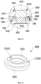
FIG. 7 is a schematic structural diagram of a composite pole provided in the embodiment one of the present application; -
FIG. 8 is a sectional view one of the composite pole provided in the embodiment one of the present application; -
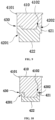
FIG. 9 is a sectional view two of the composite pole provided in the embodiment one of the present application; -
FIG. 10 is a sectional view three of the composite pole provided in the embodiment one of the present application; -
FIG. 11 is a partial enlarged view of a power battery cover in an assembled state provided in an embodiment two of the present application; -
FIG. 12 is a sectional view one of a composite pole provided in the embodiment two of the present application; and -
FIG. 13 is a sectional view two of the composite pole provided in the embodiment two of the present application. -
- 100 top cover sheet
- 110 second rectangular limiting recess
- 120 second annular limiting recess
- 130 injection hole
- 140 avoidance notch
- 200 terminal pressing block
- 210 first annular limiting recess
- 220 first countersunk hole
- 300 pole bottom plate
- 310 second countersunk hole
- 400 composite pole
- 410 aluminum base part
- 4101 first annular protrusion
- 4102 concave portion
- 411 third column body
- 412 fourth column body
- 420 copper base part
- 4201 limiting step
- 4202 extension portion
- 421 first column body
- 422 second column body
- 430 composite connection surface
- 500 sealing member
- 510 first sealing portion
- 5101 first step portion
- 520 second sealing portion
- 5102 second step portion
- 600 upper plastic member
- 610 first rectangular limiting recess
- 620 second annular protrusion
- 700 lower plastic member
- 710 third rectangular limiting recess
- 720 chamfer
- In the description of this application, it is to be noted that, unless otherwise expressly specified and limited, the terms "connected to each other", "connected" or "fixed" are to be construed in a broad sense, for example, as permanently connected or detachably connected or integrally formed; mechanically connected or electrically connected; directly connected to each other or indirectly connected to each other via an intermediary; or internal connection of two components or interaction relationship between two components. For the person of ordinary skill in the art, meanings of the above terms in the present application may be construed based on situations.
- In the present application, unless otherwise expressly specified and limited, when a first feature is described as "above" or "below" a second feature, the first feature and the second feature may be in direct contact, or be in contact via another feature between the two features. Moreover, when the first feature is described as "on", "above" or "over" the second feature, the first feature may be right on, above or over the second feature or the first feature may be diagonally on, above or over the second feature, or the first feature may be simply at a higher level than the second feature. When the first feature is described as "under", "below" or "underneath" the second feature, the first feature may be right under, below or underneath the second feature or the first feature may be diagonally under, below or underneath the second feature, or the first feature may be simply at a lower level than the second feature.
- In the description of this article, it should be understood that the orientation or position relationships indicated by the terms such as "upper", "lower", "left", "right", etc., are based on the orientation or position relationship shown in the drawings, which is only for the convenience of description and simplification of operation, and does not indicate or imply that the device or element referred to must have a specific orientation, be constructed and operated in a specific orientation. Furthermore, the terms "first" and "second" are simply used to distinguish in the description and have no special meaning.
- As shown in
FIG. 1 to FIG. 5 , a power battery cover is provided according to this embodiment. The power battery cover includes atop cover sheet 100, aterminal pressing block 200, apole bottom plate 300,composite poles 400 and a sealingmember 500. The terminalpressing block 200 is arranged above thetop cover sheet 100, and thepole bottom plate 300 is arranged below thetop cover sheet 100. Thecomposite poles 400 are formed from a copper-aluminum composite plate by means of a cold heading or stamping process, and each of thecomposite poles 400 is arranged to sequentially pass through theterminal pressing block 200, thetop cover sheet 100 and thepole bottom plate 300 from top to bottom. Thecomposite pole 400 includes analuminum base part 410 and acopper base part 420 connected to each other, thealuminum base part 410 is arranged on thecopper base part 420, end surfaces by which thealuminum base part 410 is connected to thecopper base part 420 form acomposite connection surface 430, and thecopper base part 420 is connected to thepole bottom plate 300 by laser welding. The sealingmember 500 is sleeved on thecomposite pole 400 and sandwiched between thecomposite pole 400 and thetop cover sheet 100. The sealingmember 500 can cover thecomposite connection surface 430 between thealuminum base part 410 and thecopper base part 420 in a sealing manner. Compared with the copper-aluminum composite pole 400 formed by friction welding in the related art, thecomposite pole 400 in this embodiment has fewer processing steps, and the assembly steps and assembly method are simplified, which improves the processing efficiency, and greatly reduces the material and processing costs. In addition, there is no weld joint between thealuminum base part 410 and thecopper base part 420, so the risk of fracture is small and the reliability is high. Exemplarily, the height of thecopper base part 420 is set in the range of 0.3 mm to 5 mm. - In addition, in order to facilitate the positioning of the
composite pole 400, thealuminum base part 410 is provided with a firstannular protrusion 4101, and accordingly, an upper end surface of theterminal pressing block 200 is provided with a first annular limitingrecess 210. The firstannular protrusion 4101 can abut against the first annular limitingrecess 210, thereby playing a limiting role to prevent thecomposite pole 400 from falling out. - As an exemplary solution, the
top cover sheet 100 and theterminal pressing block 200 in this embodiment are made of aluminum material. Compared with the solution in which theterminal pressing block 200 in the related art is made of copper-aluminum composite plate, theterminal pressing block 200 in this embodiment is made of pure aluminum material, the assembly method is simple, the assembly difficulty is small, the selection limitation of theterminal pressing block 200 is small, and the processing cost is low. Thepole bottom plate 300 is made of copper material. Twocomposite poles 400 and twoseals 500 are provided, and thecomposite poles 400 and theseals 500 are in one-to-one correspondence. The sealingmember 500 is made of insulating material and has a certain deformation capacity, so that the gap between thetop cover sheet 100 and thecomposite pole 400 can be filled after cold heading or stamping to ensure the reliability of the sealing. For example, the deformation amount of the sealingmember 500 in this embodiment ranges from about 25% to about 45%. - In an embodiment, referring to
FIG. 5 and FIG. 6 , the sealingmember 500 in this embodiment includes afirst sealing portion 510 and asecond sealing portion 520. Thefirst sealing portion 510 is arranged on thesecond sealing portion 520, and thefirst sealing portion 510 is arranged between thecomposite pole 400 and thetop cover sheet 100. Thefirst sealing portion 510 is arranged to cover thecomposite connection surface 430 in a sealing manner. An upper end surface of thesecond sealing portion 520 is connected to a limitingstep 4201 of thecopper base part 420 and thetop cover sheet 100, and a lower end surface of thesecond sealing portion 520 is connected to an upper end surface of thepole bottom plate 300. Exemplarily, thefirst sealing portion 510 is cylindrical, thesecond sealing portion 520 is annular, afirst step portion 5101 is formed between an inner side wall of thefirst sealing portion 510 and an upper end surface of thesecond sealing portion 520, and asecond step portion 5102 is formed between an outer side wall of thefirst sealing portion 510 and the upper end surface of thesecond sealing portion 520. Thecopper base part 420 of thecomposite pole 400 is provided with a limitingstep 4201, and the limitingstep 4201 can abut against thefirst step portion 5101, so that the sealingmember 500 can prevent thecomposite pole 400 from falling out, and a sealing path is formed between thefirst step portion 5101 and thecopper base part 420, which is used to seal the gap between thecomposite pole 400 and the sealingmember 500. - For example, referring to
FIG. 5 ,FIG. 7 and FIG. 8 , thecopper base part 420 of thecomposite pole 400 in this embodiment includes afirst column body 421 and asecond column body 422, thefirst column body 421 is connected to thealuminum base part 410, thecomposite connection surface 430 is formed between thefirst column body 421 and thealuminum base part 410, and thefirst sealing portion 510 of the sealingmember 500 covers thecomposite connection surface 430 in a sealing manner. Thesecond column body 422 is connected to thefirst column body 421. Thefirst column body 421 has the same cross section as thealuminum base part 410. Thesecond column body 422 has a smaller cross section than thefirst column body 421. Since thesecond column body 422 has a smaller cross section than thefirst column body 421, the limitingstep 4201 is formed on thecopper base part 420 of thecomposite pole 400. The limitingstep 4201 may abut against thefirst step portion 5101 of the sealingmember 500, thereby preventing thecomposite pole 400 from falling out or shaking and ensuring a good fixing effect of thecomposite pole 400. Of course, in an embodiment, referring toFIG. 9 and FIG. 10 , after thealuminum base part 410 and thecopper base part 420 are connected by cold heading or stamping, a lower end surface of thealuminum base part 410 may be formed to possibly have aconcave portion 4102, and an upper end surface of thefirst column body 421 of thecopper base part 420 is formed to have anextension portion 4202. Theextension portion 4202 and theconcave portion 4102 are connected to form acomposite connection surface 430, and thefirst sealing portion 510 of the sealingmember 500 can cover thecomposite connection surface 430 in a sealing manner. - In an embodiment, a lower end surface of the
top cover sheet 100 is provided with anavoidance notch 140, and thesecond step portion 5102 abuts against theavoidance notch 140, thereby forming another sealing path between thesecond step portion 5102 of the sealingmember 500 and theavoidance notch 140 of thetop cover sheet 100, which is used to seal the gap between thetop cover sheet 100 and the sealingmember 500, thereby ensuring a good sealing effect of the sealingmember 500 and avoiding leakage. - It is to be noted that an interference fit is formed between the
first sealing portion 510 and thecomposite pole 400 as well as between thefirst sealing portion 510 and thetop cover sheet 100, thereby ensuring a good sealing performance of the sealingmember 500 and a high reliability of the sealing. Further, before the cold heading or stamping, referring toFIG. 5 , a first sealing cavity may be formed between thefirst step portion 5101 and the limitingstep 4201 of thecopper base part 420, and a second sealing cavity may be formed between thesecond step portion 5102 and theavoidance notch 140 provided on the lower end surface of thetop cover sheet 100. The first sealing cavity and the second sealing cavity can accommodate the deformedfirst sealing portion 510 or thesecond sealing portion 520. By providing theavoidance notch 140, the accommodation space of the second sealing cavity can be increased, so that the deformedfirst sealing portion 510 or the deformedsecond sealing portion 520 can be accommodated in the second sealing cavity, avoiding the situation of insufficient accommodation space. - Continuing to refer to
FIG. 1 to FIG. 5 , the power battery cover includes anupper plastic member 600, and theupper plastic member 600 is arranged between thetop cover sheet 100 and theterminal pressing block 200. Thecomposite pole 400 is arranged to pass through theupper plastic member 600, and the sealingmember 500 is sandwiched between thecomposite pole 400 and theupper plastic member 600. Theupper plastic member 600 is made of insulating material. The arrangement of theupper plastic member 600 enables thetop cover sheet 100 to be insulated from theterminal pressing block 200 to avoid electrical connection. In an embodiment, an upper end surface of theupper plastic member 600 is provided with a first rectangular limitingrecess 610, and theterminal pressing block 200 is stuck in the first rectangular limitingrecess 610. In one aspect, with the arrangement of the first rectangular limitingrecess 610, the overall height of the power battery cover can be reduced, which is beneficial to improving the energy density of the power battery, and in another aspect, the first rectangular limitingrecess 610 can position theterminal pressing block 200, which is convenient for the assembly process, beneficial to improving the assembly efficiency, and the production efficiency of the product is high. - In an embodiment, a lower end surface of the
upper plastic member 600 is further provided with a secondannular protrusion 620, an upper end surface of thetop cover sheet 100 is formed to have a second annular limitingrecess 120, and the secondannular protrusion 620 is stuck in the second annular limitingrecess 120. With the arrangement of the second annular limitingrecess 120 and the secondannular protrusion 620, it is convenient to position thetop cover sheet 100 and theupper plastic member 600, thus ensuring accurate positioning, which is conducive to speeding up the assembly process and improving assembly efficiency. - In an embodiment, the upper end surface of the
top cover sheet 100 is formed to have a second rectangular limitingrecess 110, a second annular limitingrecess 120 is arranged on a bottom wall of the second rectangular limitingrecess 110, and theupper plastic member 600 is clamped in the second rectangular limitingrecess 110. In one aspect, with the arrangement of the second rectangular limitingrecess 110, the overall height of the power battery cover can be reduced, which is beneficial to improving the energy density of the power battery, and in another aspect, the second rectangular limitingrecess 110 can also assist in positioning theterminal pressing block 200, which is convenient for the assembly process, beneficial to improving the assembly efficiency, and the production efficiency of the product is high. - The power battery cover also includes a
lower plastic member 700, and thelower plastic member 700 is arranged between thetop cover sheet 100 and thepole bottom plate 300. Thecomposite pole 400 is arranged to pass through thelower plastic member 700, and the sealingmember 500 is sandwiched between thecomposite pole 400 and thelower plastic member 700. Thelower plastic member 700 is made of insulating material. The arrangement of thelower plastic member 700 enables thetop cover sheet 100 to be insulated from thepole bottom plate 300 to avoid electrical connection. In an embodiment, a lower end surface of thelower plastic member 700 is provided with a third rectangular limitingrecess 710, and thepole bottom plate 300 is stuck in the third rectangular limitingrecess 710. In one aspect, with the arrangement of the third rectangular limitingrecess 710, the overall height of the power battery cover can be reduced, which is beneficial to improving the energy density of the power battery, and in another aspect, the third rectangular limitingrecess 710 can position thepole bottom plate 300, which is convenient for the assembly process, beneficial to improving the assembly efficiency, and the production efficiency of the product is high. - In an embodiment, the
lower plastic member 700 is provided with a through hole, thecomposite pole 400 is arranged to pass through the through hole, and at least one of a top end and a bottom end of the through hole is provided with achamfer 720. With the arrangement of thechamfer 720, thecomposite pole 400 or the sealingmember 500 can be arranged to more smoothly pass through the through hole, which is beneficial to the assembly process and improves the assembly efficiency. - In addition, in order to facilitate the injection, the
top cover sheet 100 is further provided with aninjection hole 130 at one end thereof, and electrolyte can be injected into the shell of the power battery through theinjection hole 130. - Continuing to refer to
FIG. 5 , in order to prevent a top end of thecomposite pole 400 from extending beyond an upper end surface of theterminal pressing block 200 after assembly, in this embodiment, the upper end surface of theterminal pressing block 200 is provided with a firstcountersunk hole 220, and the diameter of the firstcountersunk hole 220 is greater than the diameter of the first annular limitingrecess 210. Moreover, in order to prevent the bottom end of thecomposite pole 400 from extending beyond a lower end surface of thepole bottom plate 300 after assembly, in this embodiment, the lower end surface of thepole bottom plate 300 is provided with a secondcountersunk hole 310, and the diameter of the secondcountersunk hole 310 is greater than the diameter of thecopper base part 420. - A power battery is further provided according to this embodiment, which includes the power battery cover in the above solution. The power battery cover in this embodiment has fewer processing steps, low assembly difficulty, and high assembly efficiency. Moreover, the overall thickness of the power battery cover is thin, which is conducive to saving the internal space of the power battery and improving the energy density of the power battery.
- A power battery cover is provided according to this embodiment, referring to
FIG. 11 and FIG. 12 , which is different from the power battery cover in Embodiment 1 in that: thecomposite pole 400 in this embodiment includes analuminum base part 410 and acopper base part 420, thealuminum base part 410 includes athird column body 411 and afourth column body 412, and thethird column body 411 is arranged on thefourth column body 412 and connected to thefourth column body 412. Thefourth column body 412 is connected to thecopper base part 420, to form acomposite connection surface 430. A firstannular protrusion 4101 is arranged on thethird column body 411 at an end away from thefourth column body 412. Thefourth column body 412 has a smaller cross section than thethird column body 411, and thefourth column body 412 has the same cross section as thecopper base part 420, so that a limitingstep 4201 is formed on thealuminum base part 410, thereby preventing thecomposite pole 400 from falling out or shaking. - The sealing
member 500 includes afirst sealing portion 510 in a cylindrical shape and asecond sealing portion 520 in an annular shape. Thefirst sealing portion 510 is arranged on thesecond sealing portion 520. Thefirst sealing portion 510 is arranged between thecomposite pole 400 and thetop cover sheet 100. Thesecond sealing portion 520 is arranged between thecomposite pole 400 and thelower plastic member 700. Thesecond sealing portion 520 is arranged to cover thecomposite connection surface 430 in a sealing manner. Afirst step portion 5101 is formed between an inner side wall of thefirst sealing portion 510 and an upper end surface of thesecond sealing portion 520. Thefirst step portion 5101 can abut against the limitingstep 4201. Asecond step portion 5102 is formed between an outer side wall of thefirst sealing portion 510 and the upper end surface of thesecond sealing portion 520. Thesecond step portion 5102 can abut against theavoidance notch 140 of thetop cover sheet 100. A lower end surface of thesecond sealing portion 520 is connected to the upper end surface of thepole bottom plate 300. In this embodiment, two sealing paths are formed on two sides of thesecond sealing portion 520 of the sealingmember 500 respectively, one of which seals the gap between thecomposite pole 400 and the sealingmember 500, and the other seals the gap between thetop cover sheet 100 and the sealingmember 500. The sealingmember 500 has a good sealing effect, and avoids leakage. - It is to be noted that an interference fit is formed between the
first sealing portion 510 and thecomposite pole 400 as well as between thefirst sealing portion 510 and thetop cover sheet 100, thereby ensuring a good sealing performance of the sealingmember 500 and a high reliability of the sealing. Further, before the cold heading or stamping, referring toFIG. 11 , a first sealing cavity may be formed between thefirst step portion 5101 and the limitingstep 4201, and a second sealing cavity may be formed between thesecond step portion 5102 and theavoidance notch 140 provided on the lower end surface of thetop cover sheet 100. The first sealing cavity and the second sealing cavity can accommodate the deformedfirst sealing portion 510 or thesecond sealing portion 520. - Of course, in an embodiment, referring to
FIG. 13 , after thealuminum base part 410 and thecopper base part 420 are connected by cold heading or stamping, a lower end surface of thefourth column body 412 of thealuminum base part 410 may be formed to possibly have aconcave portion 4102, and an upper end surface of thecopper base part 420 may be formed to have anextension portion 4202. Theextension portion 4202 and theconcave portion 4102 are connected to form acomposite connection surface 430, and thesecond sealing portion 520 of the sealingmember 500 can cover thecomposite connection surface 430 in a sealing manner. - A power battery is further provided according to this embodiment, which includes the power battery cover in the above solution. The power battery cover in this embodiment has fewer processing steps, low assembly difficulty, and high assembly efficiency. Moreover, the overall thickness of the power battery cover is thin, which is conducive to saving the internal space of the power battery and improving the energy density of the power battery.
- The remaining structures in this embodiment are the same as those in the embodiment one.
Claims (18)
- A power battery cover, comprising:a top cover sheet (100);a terminal pressing block (200) arranged above the top cover sheet (100);a pole bottom plate (300) arranged below the top cover sheet (100);composite poles (400) formed from a copper-aluminum composite plate by means of a cold heading or stamping process, wherein each of the composite poles (400) sequentially passes through the terminal pressing block (200), the top cover sheet (100) and the pole bottom plate (300) from top to bottom, each of the composite poles (400) comprises an aluminum base part (410) and a copper base part (420) connected to each other, the aluminum base part (410) is arranged on the copper base part (420), end surfaces by which the aluminum base part (410) is connected to the copper base part (420) form a composite connection surface (430), and the copper base part (420) is connected to the pole bottom plate (300); anda sealing member (500) sleeved on the composite pole (400) and sandwiched between the composite pole (400) and the top cover sheet (100), wherein the sealing member (500) covers the composite connection surface (430) in a sealing manner.
- The power battery cover according to claim 1, wherein the aluminum base part (410) is provided with a first annular protrusion (4101), an upper end surface of the terminal pressing block (200) is provided with a first annular limiting recess (210), and the first annular protrusion (4101) abuts against the first annular limiting recess (210).
- The power battery cover according to claim 1, wherein after cold heading or stamping, a lower end surface of the aluminum base part (410) is formed to have a concave portion (4102), an upper end surface of the copper base part (420) is formed to have an extension portion (4202), and the extension portion (4202) is connected to the concave portion (4102) to form the composite connection surface (430).
- The power battery cover according to claim 1, wherein the sealing member (500) comprises a first sealing portion (510) and a second sealing portion (520), the first sealing portion (510) is arranged on the second sealing portion (520), the first sealing portion (510) is arranged between the composite pole (400) and the top cover sheet (100), the first sealing portion (510) or the second sealing portion (520) covers the composite connection surface (430) in a sealing manner, an upper end surface of the second sealing portion (520) is connected to the copper base part (420) and the top cover sheet (100), and a lower end surface of the second sealing portion (520) is connected to the pole bottom plate (300).
- The power battery cover according to claim 4, wherein an interference fit is formed between the first sealing portion (510) and the composite pole (400) as well as between the first sealing portion (510) and the top cover sheet (100).
- The power battery cover according to claim 4, wherein the first sealing portion (510) is cylindrical, the second sealing portion (520) is annular, a first step portion (5101) is formed between an inner side wall of the first sealing portion (510) and the upper end surface of the second sealing portion (520), and a second step portion (5102) is formed between an outer side wall of the first sealing portion (510) and the upper end surface of the second sealing portion (520).
- The power battery cover according to claim 6, wherein the composite pole (400) is provided with a limiting step (4201), the limiting step (4201) abuts against the first step portion (5101), and the aluminum base part (410) is provided with the limiting step (4201); or
the copper base part (420) is provided with the limiting step (4201). - The power battery cover according to claim 7, wherein the copper base part (420) comprises a first column body (421) and a second column body (422), the first column body (421) is connected to the aluminum base part (410), the second column body (422) is connected to the first column body (421), the first column body (421) has a same cross section as the aluminum base part (410), the second column body (422) has a smaller cross section than the first column body (421), and the limiting step (4201) is formed between the first column body (421) and the second column body (422).
- The power battery cover according to claim 7, wherein the aluminum base part (410) comprises a third column body (411) and a fourth column body (412), the third column body (411) is arranged on the fourth column body (412) and connected to the fourth column body (412), the fourth column body (412) is connected to the copper base part (420), the fourth column body (412) has a smaller cross section than the third column body (411), the fourth column body (412) has a same cross section as the copper base part (420), and the limiting step (4201) is formed between the third column body (411) and the fourth column body (412).
- The power battery cover according to claim 6, wherein a lower end surface of the top cover sheet (100) is provided with an avoidance notch (140), and the second step portion (5102) abuts against the avoidance notch (140).
- The power battery cover according to any one of claims 1 to 10, comprising an upper plastic member (600), wherein the upper plastic member (600) is arranged between the top cover sheet (100) and the terminal pressing block (200), the composite pole (400) is arranged to pass through the upper plastic member (600), and the sealing member (500) is sandwiched between the composite pole (400) and the upper plastic member (600).
- The power battery cover according to claim 11, wherein an upper end surface of the upper plastic member (600) is provided with a first rectangular limiting recess (610), and the terminal pressing block (200) is stuck in the first rectangular limiting recess (610).
- The power battery cover according to claim 11, wherein a lower end surface of the upper plastic member (600) is provided with a second annular protrusion (620), an upper end surface of the top cover sheet (100) is formed to have a second annular limiting recess (120), and the second annular protrusion (620) is stuck in the second annular limiting recess (120).
- The power battery cover according to claim 13, wherein the upper end surface of the top cover sheet (100) is formed to have a second rectangular limiting recess (110), the second annular limiting recess (120) is arranged on a bottom wall of the second rectangular limiting recess (110), and the upper plastic member (600) is stuck in the second rectangular limiting recess (110).
- The power battery cover according to any one of claims 1 to 10, comprising a lower plastic member (700), wherein the lower plastic member (700) is arranged between the top cover sheet (100) and the pole bottom plate (300), the composite pole (400) is arranged to pass through the lower plastic member (700), and the sealing member (500) is sandwiched between the composite pole (400) and the lower plastic member (700).
- The power battery cover according to claim 15, wherein a lower end surface of the lower plastic member (700) is provided with a third rectangular limiting recess (710), and the pole bottom plate (300) is stuck in the third rectangular limiting groove (710).
- The power battery cover according to claim 15, wherein the lower plastic member (700) is provided with a through hole, the composite pole (400) is arranged to pass through the through hole, and at least one of a top end and a bottom end of the through hole is provided with a chamfer (720).
- A power battery, comprising the power battery cover according to any one of claims 1 to 17.
Applications Claiming Priority (2)
| Application Number | Priority Date | Filing Date | Title |
|---|---|---|---|
| CN202223339926.2U CN219106463U (en) | 2022-12-12 | 2022-12-12 | Power battery cover and power battery |
| PCT/CN2022/143794 WO2024124634A1 (en) | 2022-12-12 | 2022-12-30 | Power battery cover and power battery |
Publications (2)
| Publication Number | Publication Date |
|---|---|
| EP4568004A1 true EP4568004A1 (en) | 2025-06-11 |
| EP4568004A4 EP4568004A4 (en) | 2025-08-20 |
Family
ID=86428019
Family Applications (1)
| Application Number | Title | Priority Date | Filing Date |
|---|---|---|---|
| EP22968335.4A Pending EP4568004A4 (en) | 2022-12-12 | 2022-12-30 | Power battery cover and power battery |
Country Status (4)
| Country | Link |
|---|---|
| US (1) | US20250158253A1 (en) |
| EP (1) | EP4568004A4 (en) |
| CN (1) | CN219106463U (en) |
| WO (1) | WO2024124634A1 (en) |
Families Citing this family (6)
| Publication number | Priority date | Publication date | Assignee | Title |
|---|---|---|---|---|
| CN116748435A (en) * | 2023-06-09 | 2023-09-15 | 湖北亿纬动力有限公司 | Cold heading forming process of negative pole, negative pole, battery top cover and battery |
| CN221766863U (en) * | 2024-01-26 | 2024-09-24 | 株式会社Aesc日本 | Cover plate assembly, secondary battery, battery pack and electronic equipment |
| CN117937068A (en) * | 2024-03-21 | 2024-04-26 | 常州瑞德丰精密技术有限公司 | Composite pole block forming method |
| CN223297017U (en) * | 2024-09-06 | 2025-09-02 | 惠州亿纬动力电池有限公司 | Conductive structure, cover plate assembly and battery monomer |
| JP2026049706A (en) * | 2024-09-06 | 2026-03-18 | 恵州億緯動力電池有限公司 | Conductive module, cover assembly, and battery unit |
| CN119786902B (en) * | 2025-03-11 | 2025-05-30 | 蜂巢能源科技股份有限公司 | Pole, battery cover and single battery |
Family Cites Families (7)
| Publication number | Priority date | Publication date | Assignee | Title |
|---|---|---|---|---|
| JP5966916B2 (en) * | 2012-12-26 | 2016-08-10 | 株式会社豊田自動織機 | Power storage device |
| CN107248554A (en) * | 2017-06-27 | 2017-10-13 | 东莞塔菲尔新能源科技有限公司 | Top cover structure of power battery and electrokinetic cell |
| CN208028095U (en) * | 2017-10-11 | 2018-10-30 | 东莞塔菲尔新能源科技有限公司 | A kind of power battery head cover insulating part and power battery head cover assembling structure |
| CN214043929U (en) * | 2020-09-10 | 2021-08-24 | 武汉富航精密工业有限公司 | Structure of power battery copper-aluminum composite pole |
| CN213989132U (en) * | 2020-12-11 | 2021-08-17 | 厦门海辰新能源科技有限公司 | Light-duty utmost point post subassembly, top cap structure and power battery |
| CN215266482U (en) * | 2021-05-14 | 2021-12-21 | 深圳市科达利实业股份有限公司 | Power battery cover and power battery |
| CN114361689B (en) * | 2021-11-23 | 2022-07-26 | 宁波震裕汽车部件有限公司 | Top cover structure of power battery |
-
2022
- 2022-12-12 CN CN202223339926.2U patent/CN219106463U/en active Active
- 2022-12-30 EP EP22968335.4A patent/EP4568004A4/en active Pending
- 2022-12-30 WO PCT/CN2022/143794 patent/WO2024124634A1/en not_active Ceased
-
2025
- 2025-01-15 US US19/021,959 patent/US20250158253A1/en active Pending
Also Published As
| Publication number | Publication date |
|---|---|
| WO2024124634A1 (en) | 2024-06-20 |
| US20250158253A1 (en) | 2025-05-15 |
| CN219106463U (en) | 2023-05-30 |
| EP4568004A4 (en) | 2025-08-20 |
Similar Documents
| Publication | Publication Date | Title |
|---|---|---|
| EP4568004A1 (en) | Power battery cover and power battery | |
| JP2022512517A (en) | battery | |
| US20240106093A1 (en) | Battery and electronic product | |
| US20240195029A1 (en) | Power battery cover and power battery | |
| US12119503B2 (en) | Cap assembly and secondary battery | |
| EP4322314A1 (en) | Lithium battery and preparation method therefor | |
| EP4571996A1 (en) | Post terminal, top cover structure, battery, battery module and battery pack | |
| CN219937299U (en) | Battery case and battery | |
| US20230387521A1 (en) | Cylindrical battery and electronic device | |
| US20250158178A1 (en) | Battery, battery module, and electric device | |
| JP2025539144A (en) | Electrochemical devices and electrical devices | |
| CN209104289U (en) | Secondary battery | |
| US20240106094A1 (en) | Battery | |
| JP6170937B2 (en) | Power storage device and power storage module | |
| CN213304244U (en) | Battery shell assembly and battery | |
| CN218586265U (en) | Battery pack | |
| CN219801070U (en) | Power battery shell structure and power battery | |
| EP4475298A1 (en) | Battery housing assembly and lithium ion battery | |
| US20230145494A1 (en) | Electrochemical apparatus and electric apparatus | |
| CN223858143U (en) | Electrode structure and battery | |
| US20220109209A1 (en) | Battery module and manufacturing method of battery module | |
| US20210280837A1 (en) | Battery and manufacturing method of battery | |
| CN115000642A (en) | Square laminated battery | |
| CN219843056U (en) | Battery cover plate and battery | |
| CN221009068U (en) | Battery top cover, battery and power utilization device |
Legal Events
| Date | Code | Title | Description |
|---|---|---|---|
| STAA | Information on the status of an ep patent application or granted ep patent |
Free format text: STATUS: THE INTERNATIONAL PUBLICATION HAS BEEN MADE |
|
| PUAI | Public reference made under article 153(3) epc to a published international application that has entered the european phase |
Free format text: ORIGINAL CODE: 0009012 |
|
| STAA | Information on the status of an ep patent application or granted ep patent |
Free format text: STATUS: REQUEST FOR EXAMINATION WAS MADE |
|
| 17P | Request for examination filed |
Effective date: 20250305 |
|
| AK | Designated contracting states |
Kind code of ref document: A1 Designated state(s): AL AT BE BG CH CY CZ DE DK EE ES FI FR GB GR HR HU IE IS IT LI LT LU LV MC ME MK MT NL NO PL PT RO RS SE SI SK SM TR |
|
| A4 | Supplementary search report drawn up and despatched |
Effective date: 20250721 |
|
| RIC1 | Information provided on ipc code assigned before grant |
Ipc: H01M 50/562 20210101AFI20250715BHEP Ipc: H01M 50/147 20210101ALI20250715BHEP Ipc: H01M 50/15 20210101ALI20250715BHEP Ipc: H01M 50/176 20210101ALI20250715BHEP Ipc: H01M 50/184 20210101ALI20250715BHEP Ipc: H01M 50/186 20210101ALI20250715BHEP Ipc: H01M 50/188 20210101ALI20250715BHEP Ipc: H01M 50/193 20210101ALI20250715BHEP Ipc: H01M 50/55 20210101ALI20250715BHEP Ipc: H01M 50/552 20210101ALI20250715BHEP Ipc: H01M 50/553 20210101ALI20250715BHEP Ipc: H01M 50/566 20210101ALI20250715BHEP Ipc: H01M 50/586 20210101ALI20250715BHEP Ipc: H01M 50/588 20210101ALI20250715BHEP |
|
| DAV | Request for validation of the european patent (deleted) | ||
| DAX | Request for extension of the european patent (deleted) |