EP4567986A1 - Battery and electrical device - Google Patents
Battery and electrical device Download PDFInfo
- Publication number
- EP4567986A1 EP4567986A1 EP22955324.3A EP22955324A EP4567986A1 EP 4567986 A1 EP4567986 A1 EP 4567986A1 EP 22955324 A EP22955324 A EP 22955324A EP 4567986 A1 EP4567986 A1 EP 4567986A1
- Authority
- EP
- European Patent Office
- Prior art keywords
- battery
- battery unit
- frame body
- present application
- longitudinal beam
- Prior art date
- Legal status (The legal status is an assumption and is not a legal conclusion. Google has not performed a legal analysis and makes no representation as to the accuracy of the status listed.)
- Pending
Links
Images



Classifications
-
- H—ELECTRICITY
- H01—ELECTRIC ELEMENTS
- H01M—PROCESSES OR MEANS, e.g. BATTERIES, FOR THE DIRECT CONVERSION OF CHEMICAL ENERGY INTO ELECTRICAL ENERGY
- H01M50/00—Constructional details or processes of manufacture of the non-active parts of electrochemical cells other than fuel cells, e.g. hybrid cells
- H01M50/20—Mountings; Secondary casings or frames; Racks, modules or packs; Suspension devices; Shock absorbers; Transport or carrying devices; Holders
- H01M50/233—Mountings; Secondary casings or frames; Racks, modules or packs; Suspension devices; Shock absorbers; Transport or carrying devices; Holders characterised by physical properties of casings or racks, e.g. dimensions
- H01M50/242—Mountings; Secondary casings or frames; Racks, modules or packs; Suspension devices; Shock absorbers; Transport or carrying devices; Holders characterised by physical properties of casings or racks, e.g. dimensions adapted for protecting batteries against vibrations, collision impact or swelling
-
- B—PERFORMING OPERATIONS; TRANSPORTING
- B60—VEHICLES IN GENERAL
- B60L—PROPULSION OF ELECTRICALLY-PROPELLED VEHICLES; SUPPLYING ELECTRIC POWER FOR AUXILIARY EQUIPMENT OF ELECTRICALLY-PROPELLED VEHICLES; ELECTRODYNAMIC BRAKE SYSTEMS FOR VEHICLES IN GENERAL; MAGNETIC SUSPENSION OR LEVITATION FOR VEHICLES; MONITORING OPERATING VARIABLES OF ELECTRICALLY-PROPELLED VEHICLES; ELECTRIC SAFETY DEVICES FOR ELECTRICALLY-PROPELLED VEHICLES
- B60L50/00—Electric propulsion with power supplied within the vehicle
- B60L50/50—Electric propulsion with power supplied within the vehicle using propulsion power supplied by batteries or fuel cells
- B60L50/60—Electric propulsion with power supplied within the vehicle using propulsion power supplied by batteries or fuel cells using power supplied by batteries
- B60L50/64—Constructional details of batteries specially adapted for electric vehicles
-
- B—PERFORMING OPERATIONS; TRANSPORTING
- B60—VEHICLES IN GENERAL
- B60L—PROPULSION OF ELECTRICALLY-PROPELLED VEHICLES; SUPPLYING ELECTRIC POWER FOR AUXILIARY EQUIPMENT OF ELECTRICALLY-PROPELLED VEHICLES; ELECTRODYNAMIC BRAKE SYSTEMS FOR VEHICLES IN GENERAL; MAGNETIC SUSPENSION OR LEVITATION FOR VEHICLES; MONITORING OPERATING VARIABLES OF ELECTRICALLY-PROPELLED VEHICLES; ELECTRIC SAFETY DEVICES FOR ELECTRICALLY-PROPELLED VEHICLES
- B60L50/00—Electric propulsion with power supplied within the vehicle
- B60L50/50—Electric propulsion with power supplied within the vehicle using propulsion power supplied by batteries or fuel cells
- B60L50/60—Electric propulsion with power supplied within the vehicle using propulsion power supplied by batteries or fuel cells using power supplied by batteries
- B60L50/66—Arrangements of batteries
-
- H—ELECTRICITY
- H01—ELECTRIC ELEMENTS
- H01M—PROCESSES OR MEANS, e.g. BATTERIES, FOR THE DIRECT CONVERSION OF CHEMICAL ENERGY INTO ELECTRICAL ENERGY
- H01M50/00—Constructional details or processes of manufacture of the non-active parts of electrochemical cells other than fuel cells, e.g. hybrid cells
- H01M50/20—Mountings; Secondary casings or frames; Racks, modules or packs; Suspension devices; Shock absorbers; Transport or carrying devices; Holders
- H01M50/202—Casings or frames around the primary casing of a single cell or a single battery
-
- H—ELECTRICITY
- H01—ELECTRIC ELEMENTS
- H01M—PROCESSES OR MEANS, e.g. BATTERIES, FOR THE DIRECT CONVERSION OF CHEMICAL ENERGY INTO ELECTRICAL ENERGY
- H01M50/00—Constructional details or processes of manufacture of the non-active parts of electrochemical cells other than fuel cells, e.g. hybrid cells
- H01M50/20—Mountings; Secondary casings or frames; Racks, modules or packs; Suspension devices; Shock absorbers; Transport or carrying devices; Holders
- H01M50/204—Racks, modules or packs for multiple batteries or multiple cells
- H01M50/207—Racks, modules or packs for multiple batteries or multiple cells characterised by their shape
- H01M50/209—Racks, modules or packs for multiple batteries or multiple cells characterised by their shape adapted for prismatic or rectangular cells
-
- H—ELECTRICITY
- H01—ELECTRIC ELEMENTS
- H01M—PROCESSES OR MEANS, e.g. BATTERIES, FOR THE DIRECT CONVERSION OF CHEMICAL ENERGY INTO ELECTRICAL ENERGY
- H01M50/00—Constructional details or processes of manufacture of the non-active parts of electrochemical cells other than fuel cells, e.g. hybrid cells
- H01M50/20—Mountings; Secondary casings or frames; Racks, modules or packs; Suspension devices; Shock absorbers; Transport or carrying devices; Holders
- H01M50/249—Mountings; Secondary casings or frames; Racks, modules or packs; Suspension devices; Shock absorbers; Transport or carrying devices; Holders specially adapted for aircraft or vehicles, e.g. cars or trains
-
- H—ELECTRICITY
- H01—ELECTRIC ELEMENTS
- H01M—PROCESSES OR MEANS, e.g. BATTERIES, FOR THE DIRECT CONVERSION OF CHEMICAL ENERGY INTO ELECTRICAL ENERGY
- H01M50/00—Constructional details or processes of manufacture of the non-active parts of electrochemical cells other than fuel cells, e.g. hybrid cells
- H01M50/20—Mountings; Secondary casings or frames; Racks, modules or packs; Suspension devices; Shock absorbers; Transport or carrying devices; Holders
- H01M50/262—Mountings; Secondary casings or frames; Racks, modules or packs; Suspension devices; Shock absorbers; Transport or carrying devices; Holders with fastening means, e.g. locks
- H01M50/264—Mountings; Secondary casings or frames; Racks, modules or packs; Suspension devices; Shock absorbers; Transport or carrying devices; Holders with fastening means, e.g. locks for cells or batteries, e.g. straps, tie rods or peripheral frames
-
- H—ELECTRICITY
- H01—ELECTRIC ELEMENTS
- H01M—PROCESSES OR MEANS, e.g. BATTERIES, FOR THE DIRECT CONVERSION OF CHEMICAL ENERGY INTO ELECTRICAL ENERGY
- H01M50/00—Constructional details or processes of manufacture of the non-active parts of electrochemical cells other than fuel cells, e.g. hybrid cells
- H01M50/20—Mountings; Secondary casings or frames; Racks, modules or packs; Suspension devices; Shock absorbers; Transport or carrying devices; Holders
- H01M50/271—Lids or covers for the racks or secondary casings
-
- H—ELECTRICITY
- H01—ELECTRIC ELEMENTS
- H01M—PROCESSES OR MEANS, e.g. BATTERIES, FOR THE DIRECT CONVERSION OF CHEMICAL ENERGY INTO ELECTRICAL ENERGY
- H01M50/00—Constructional details or processes of manufacture of the non-active parts of electrochemical cells other than fuel cells, e.g. hybrid cells
- H01M50/20—Mountings; Secondary casings or frames; Racks, modules or packs; Suspension devices; Shock absorbers; Transport or carrying devices; Holders
- H01M50/289—Mountings; Secondary casings or frames; Racks, modules or packs; Suspension devices; Shock absorbers; Transport or carrying devices; Holders characterised by spacing elements or positioning means within frames, racks or packs
-
- H—ELECTRICITY
- H01—ELECTRIC ELEMENTS
- H01M—PROCESSES OR MEANS, e.g. BATTERIES, FOR THE DIRECT CONVERSION OF CHEMICAL ENERGY INTO ELECTRICAL ENERGY
- H01M2220/00—Batteries for particular applications
- H01M2220/20—Batteries in motive systems, e.g. vehicle, ship, plane
-
- Y—GENERAL TAGGING OF NEW TECHNOLOGICAL DEVELOPMENTS; GENERAL TAGGING OF CROSS-SECTIONAL TECHNOLOGIES SPANNING OVER SEVERAL SECTIONS OF THE IPC; TECHNICAL SUBJECTS COVERED BY FORMER USPC CROSS-REFERENCE ART COLLECTIONS [XRACs] AND DIGESTS
- Y02—TECHNOLOGIES OR APPLICATIONS FOR MITIGATION OR ADAPTATION AGAINST CLIMATE CHANGE
- Y02E—REDUCTION OF GREENHOUSE GAS [GHG] EMISSIONS, RELATED TO ENERGY GENERATION, TRANSMISSION OR DISTRIBUTION
- Y02E60/00—Enabling technologies; Technologies with a potential or indirect contribution to GHG emissions mitigation
- Y02E60/10—Energy storage using batteries
Definitions
- the present application relates to the technical field of batteries, and more particularly to a battery and an electrical apparatus.
- the batteries are not very safe during transportation or use, posing a significant potential safety hazard.
- the present application provides a battery and an electrical apparatus, which can effectively improve the safety of the battery so that the battery has a lower potential safety hazard.
- the present application provides a battery, including:
- the bearing body when the battery unit is arranged in the hollow region, the bearing body can limit and fix the battery unit along the thickness direction of the frame body to meet the requirements of assembly of the battery unit.
- the battery unit is spaced apart from the frame body, which can greatly reduce the possibility of the battery unit colliding with the frame body and becoming deformed during transportation and use, thereby reducing the risk of deformation or even explosion of the battery unit, so that the battery can have higher safety performance.
- the frame body includes a first longitudinal beam and a second longitudinal beam spaced apart along its width direction, and a first transverse beam and a second transverse beam spaced apart along its length direction.
- the first longitudinal beam, the first transverse beam, the second longitudinal beam, and the second transverse beam are connected end to end in sequence and enclosed to form the hollow region.
- a battery unit is generally a cuboid or cylinder, by providing a rectangular hollow region, the hollow region can be fully utilized and a battery unit of a greater volume can be arranged in the hollow region, so that the battery can have higher space utilization.
- the battery unit is arranged between and spaced apart from the first longitudinal beam and the second longitudinal beam, and the battery unit is arranged between and spaced apart from the first transverse beam and the second transverse beam.
- the distance between the battery unit and the first transverse beam is Y 1
- the distance between the battery unit and the second transverse beam is Y 2
- Y 1 satisfies the condition: 30 mm ⁇ Y 1 ⁇ 250 mm
- Y 2 satisfies the condition: 30 mm ⁇ Y 2 ⁇ 250 mm.
- the battery unit can be prevented from colliding with the first transverse beam and/or the second transverse beam, so that the battery has better safety.
- Y 1 satisfies the condition: 50 mm ⁇ Y 1 ⁇ 120 mm
- Y 2 satisfies the condition: 50 mm ⁇ Y 2 ⁇ 120 mm.
- the battery unit can be prevented from colliding with the first transverse beam and/or the second transverse beam, and the distance between the battery unit and the first transverse beam and/or the second transverse beam is not too large, so that the battery can have better space utilization and safety.
- the distance between the battery unit 13 and the first longitudinal beam 112 is X 1
- the distance between the battery unit 13 and the second longitudinal beam 113 is X 2
- X 1 satisfies the condition: 30 mm ⁇ X 1 ⁇ 120 mm
- X 2 satisfies the condition: 30 mm ⁇ X 2 ⁇ 120 mm.
- the battery unit can be prevented from colliding with the first longitudinal beam and/or the second longitudinal beam, so that the battery can have better safety.
- X 1 satisfies the condition: 35 mm ⁇ X 1 ⁇ 80 mm
- X 2 satisfies the condition: 35 mm ⁇ X 2 ⁇ 80 mm.
- the battery unit can be prevented from colliding with the first longitudinal beam and/or the second longitudinal beam, and the distance between the battery unit and the first longitudinal beam and/or the second longitudinal beam is not too large, so that the battery can have better space utilization and safety.
- a cover body connected to the frame body is further included, the cover body being provided on the side of the battery unit facing away from the bearing body.
- the bearing body has a bearing surface facing the battery unit, and a projection of the cover body on the bearing surface at least partially covers a projection of the battery unit on the bearing surface.
- the cover body By setting the projection of the cover body on the bearing surface to at least partially cover the projection of the battery unit on the bearing surface, the cover body can be located below the battery unit and seal at least part of the hollow region, thereby helping to reduce the interference with the battery unit from the external environment where the battery is located.
- the projection of the cover body on the bearing surface completely covers the projection of the battery unit on the bearing surface.
- the cover body can further reduce the interference with the battery unit from the external environment where the battery is located.
- the cover body cooperates with the bearing body and is configured to seal the battery unit within the hollow region.
- the battery unit sealed within the hollow region cannot come into contact with water vapor, air, and other substances in the external environment, thereby preventing interference with the operation of the battery unit from the external environment, so that the battery unit can have better operating reliability and service life.
- the present application provides an electrical apparatus including the battery according to any one of the above embodiments, where the battery is configured to provide electric energy for the electrical apparatus.
- first and second are used for descriptive purposes only, and cannot be construed as indicating or implying relative importance or implicitly indicating the number of technical features indicated. Therefore, a feature defined by “first” or “second” may expressly or implicitly include at least one of the features. In the description of the present application, the meaning of "a plurality of” is at least two, for example two or three, unless otherwise explicitly and specifically defined.
- the terms “mount,” “link,” “connect” and “fix” should be broadly understood, for example, they may be a fixed connection or a detachable connection or be integrated; or may be a mechanical connection or an electrical connection; or may be a direct connection or an indirect connection through an intermediate medium, or may be a communication between the interior of two elements or the interaction of two elements, unless otherwise specifically defined.
- the specific meanings of the above terms in the present application can be understood according to specific situations.
- a first feature being “on” or “under” a second feature may be the case that the first feature is in direct contact with the second feature, or the first feature is in indirect contact with the second feature via an intermediate medium.
- the expression the first feature being “over,” “above” and “on top of” the second feature may be a case that the first feature is directly above or obliquely above the second feature, or only means that the level of the first feature is higher than that of the second feature.
- the expression the first feature being "below,” “underneath” or “under” the second feature may be a case that the first feature is directly underneath or obliquely underneath the second feature, or only means that the level of the first feature is lower than that of the second feature.
- Batteries are used in energy storage power source systems such as hydraulic, thermal, wind and solar power stations as well as in electric vehicles such as electric bicycles, electric motorcycles and electric cars, and military equipment and aerospace fields. With the continuous expansion of the application field of batteries, the market demand is also constantly expanding.
- batteries are not very safe during transportation or use, posing a significant potential safety hazard.
- the main cause for the low safety is that during transportation and use, the battery unit in the battery is prone to collision with the frame body in the battery, causing the battery unit to deform or even explode.
- the battery includes a frame body, a bearing body, and a battery unit.
- a hollow region is formed in the internal structure of the frame body.
- the bearing body is mated to the frame body.
- the battery unit is provided in the hollow region and spaced apart from the frame body.
- the battery unit is arranged on one side of the bearing body along a thickness direction of the frame body, and the battery unit is connected to the bearing body.
- the battery disclosed in the embodiments of the present application can be used, without limitation, in an electrical apparatus such as a vehicle, a ship, or an aircraft.
- a power source system of the electrical apparatus may be composed of the battery and the like disclosed in the present application, which is beneficial to alleviating and automatically adjusting deterioration of expansion force of the battery core, replenishing the electrolyte consumed, and improving the stability of battery performance and prolonging the battery life.
- Embodiments of the present application provide an electrical apparatus using a battery as a power source.
- the electrical apparatus may be, but is not limited to, a mobile phone, a tablet, a laptop, an electric toy, an electric tool, a battery cart, an electric vehicle, a ship, a spacecraft, and the like.
- the electric toy may include a fixed or mobile electric toy, such as a game console, an electric car toy, an electric ship toy, an electric airplane toy, and the like.
- the spacecraft may include an airplane, a rocket, a space shuttle, a spaceship, and the like.
- the following embodiments are illustrated with an example in which the electrical apparatus according to an embodiment of the present application is a vehicle.
- FIG. 1 is a schematic structural view of a vehicle 100 provided in some embodiments of the present application.
- the vehicle 100 may be a fuel vehicle, a gas vehicle or a new energy vehicle.
- the new energy vehicle may be an all-electric vehicle, a hybrid vehicle, an extended-range vehicle, or the like.
- a battery 10 is provided at the bottom of the vehicle 100.
- the battery 10 may be used as a power supply for the vehicle 100, for example, the battery 10 may be used as an operating power source for the vehicle 100.
- the vehicle 100 may further include a controller 20 and a motor 30.
- the controller 20 is configured to control the battery 10 to supply power to the motor 30, for example, for the operation power demand for starting, navigation and driving of the vehicle 100.
- the battery 10 may not only be used as the operating power source for the vehicle 100, but also as a driving power source for the vehicle 100, to replace or partially replace fuel or natural gas to provide driving power for the vehicle 100.
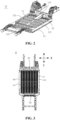
- FIG. 2 is a schematic structural view of the battery 10 provided by some embodiments of the present application
- FIG. 3 is a top view of the battery 10 provided by some embodiments of the present application with the bearing body 12 removed.
- the battery 10 includes a frame body 11, a bearing body 12, and a battery unit 13.
- a hollow region 111 is formed in the internal structure of the frame body 11.
- the bearing body 12 is mated to the frame body 11.
- the battery unit 13 is arranged in the hollow region 111 and is spaced apart from the frame body 11.
- the battery unit 13 is arranged on one side of the bearing body 12 along the thickness direction of the frame body 11, and the battery unit 13 is connected to the bearing body 12.
- the battery unit 13 includes a plurality of battery cells, all of which may be connected in series or parallel or series-parallel connection to form the battery unit 13.
- the series-parallel connection means that some of the plurality of battery cells are connected in series and some are connected in parallel. All the battery cells may be directly connected in series or parallel or in series-parallel connection, and then the battery unit 13 composed of the plurality of battery cells may be accommodated in the hollow region 111.
- the plurality of battery cells may first be connected in series or parallel or in series-parallel connection to constitute a form of battery module, and then a plurality of battery modules are connected in series, parallel, or in series-parallel connection to form a battery unit 13, which is accommodated in the hollow region 111.
- the battery unit 13 may be arranged on the upper side of the bearing body 12, or alternatively the battery unit 13 may be arranged on the lower side of the bearing body 12.
- the battery unit 13 is located on the lower side of the bearing body 12, and after the battery 10 is assembled, the bearing body 12 can also be used as the bottom plate of the chassis of the vehicle 100, and the body of the vehicle 100 is borne on the upper side of the bearing body 12 facing away from the battery unit 13.
- the frame body 11 is a structure that has a certain space inside, which can be utilized to accommodate at least the battery unit 13.
- the shape of the frame body 11 may be designed in various ways, for example, the shape of the frame body 11 may be designed to be square, circular, elliptical, or the like.
- the hollow region 111 refers to a space in the frame body 11 for at least accommodating the battery unit 13.
- the bearing body 12 may be located in the hollow region 111 or outside the hollow region 111.
- the hollow region 111 is divided by the bearing body 12 into a first area and a second area.
- the first area is located on the side of the bearing body 12 facing the battery unit 13 and is configured to accommodate the battery unit 13.
- the second area is located on the side of the bearing body 12 facing away from the battery unit 13 and is configured to accommodate components in the vehicle 100 other than the battery unit 13.
- the hollow region 111 is only configured to accommodate the battery unit 13.
- the bearing body 12 may be of a plate shape, a sheet shape, or other shapes.
- the battery unit 13 and the bearing body 12 may be connected by bonding, screwing, or other connection means.
- the bearing body 12 can limit and fix the battery unit 13 along the thickness direction of the frame body 11 to meet the requirements of assembly of the battery unit 13.
- the battery unit 13 is spaced apart from the frame body 11, which can greatly reduce the possibility of the battery unit 13 colliding with the frame body 11 and becoming deformed during transportation and use, thereby reducing the risk of deformation or even explosion of the battery unit 13, so that the battery 10 can have higher safety performance.
- FIG. 4 is a front sectional view of a battery 10 in an embodiment of the present application
- FIG. 5 is a side sectional view of a battery 10 in an embodiment of the present application
- FIG. 6 is a schematic plan view of the frame body 11 in the battery mated to the battery 10 in some embodiments of the present application.
- the frame body 11 includes a first longitudinal beam 112 and a second longitudinal beam 113 spaced apart along its width direction X, and a first transverse beam 114 and a second transverse beam 115 spaced apart along its length direction Y.
- the first longitudinal beam 112, the first transverse beam 114, the second longitudinal beam 113, and the second transverse beam 115 are connected end to end in sequence and enclosed to form the hollow region 111.
- the first longitudinal beam 112 and the second longitudinal beam 113 both extend along the length direction Y of the frame body 11, the first transverse beam 114 and the second transverse beam 115 both extend along the width direction X of the frame body 11, and the first longitudinal beam 112, the first transverse beam 114, the second longitudinal beam 113, and the second transverse beam 115 are connected end to end in sequence and enclosed to form a rectangular hollow region 111.
- the battery unit 13 is generally a cuboid or a cylinder, by providing the rectangular hollow region 111, the hollow region 111 can be fully utilized and the battery unit 13 of a greater volume can be arranged in the hollow region 111, so that the battery 10 can have higher space utilization.
- the battery unit 13 is arranged between and spaced apart from the first longitudinal beam 112 and the second longitudinal beam 113, and the battery unit 13 is arranged between and spaced apart from the first transverse beam 114 and the second transverse beam 115.
- the distance between the battery unit 13 and the first transverse beam 114 is Y 1
- the distance between the battery unit 13 and the second transverse beam 115 is Y 2
- Y 1 satisfies the condition: 30 mm ⁇ Y 1 ⁇ 250 mm
- Y 2 satisfies the condition: 30 mm ⁇ Y 2 ⁇ 250 mm.
- Y 1 satisfies the condition: 30 mm ⁇ Y 1 ⁇ 250 mm; or, only Y 2 satisfies the condition: 30 mm ⁇ Y 2 ⁇ 250 mm; or, both Y 1 and Y 2 satisfy the conditions: 30 mm ⁇ Y 1 ⁇ 250 mm and 30 mm ⁇ Y 2 ⁇ 250 mm.
- the battery unit 13 can be prevented from colliding with the first transverse beam 114 and/or the second transverse beam 115, so that the battery 10 has better safety.
- Y 1 satisfies the condition: 50 mm ⁇ Y 1 ⁇ 120 mm
- Y 2 satisfies the condition: 50 mm ⁇ Y 2 ⁇ 120 mm.
- Y 1 satisfies the condition: 50 mm ⁇ Y 1 ⁇ 120 mm; or, only Y 2 satisfies the condition: 50 mm ⁇ Y 2 ⁇ 120 mm; or, both Y 1 and Y 2 satisfy the conditions: 50 mm ⁇ Y 1 ⁇ 120 mm and 50 mm ⁇ Y 2 ⁇ 120 mm.
- the battery unit 13 can be prevented from colliding with the first transverse beam 114 and/or the second transverse beam 115, and the distance between the battery unit 13 and the first transverse beam 114 and/or the second transverse beam 115 is not too large, so that the battery 10 can have better space utilization and safety.
- the distance between the battery unit 13 and the first longitudinal beam 112 is X 1
- the distance between the battery unit 13 and the second longitudinal beam 113 is X 2
- X 1 satisfies the condition: 30 mm ⁇ X 1 ⁇ 120 mm
- X 2 satisfies the condition: 30 mm ⁇ X 2 ⁇ 120 mm.
- only X 1 may satisfy the condition: 30 mm ⁇ X 1 ⁇ 120 mm; or only X 2 may satisfy the condition: 30 mm ⁇ X 2 ⁇ 120 mm; or both X 1 and X 2 may satisfy the conditions: 30 mm ⁇ X 1 ⁇ 120 mm and 30 mm ⁇ X 2 ⁇ 120 mm.
- the battery unit 13 can be prevented from colliding with the first longitudinal beam 112 and/or the second longitudinal beam 113, so that the battery 10 has better safety.
- X 1 satisfies the condition: 35 mm ⁇ X 1 ⁇ 80 mm
- X 2 satisfies the condition: 35 mm ⁇ X 2 ⁇ 80 mm.
- X 1 satisfies the condition: 35 mm ⁇ X 1 ⁇ 80 mm; or, only X 2 satisfies the condition: 35 mm ⁇ X 2 ⁇ 80 mm; or, both X 1 and X 2 satisfy the conditions: 35 mm ⁇ X 1 ⁇ 80 mm and 35 mm ⁇ X 2 ⁇ 80 mm.
- the battery unit 13 can be prevented from colliding with the first longitudinal beam 112 and/or the second longitudinal beam 113, and the distance between the battery unit 13 and the first longitudinal beam 112 and/or the second longitudinal beam 113 is not too large, so that the battery 10 can have better space utilization and safety.
- the battery 10 further includes a cover body 14 connected to the frame body 11, and the cover body 14 is arranged on the side of the battery unit 13 facing away from the bearing body 12.
- the bearing body 12 has a bearing surface 121 facing the battery unit 13, and the projection of the cover body 14 on the bearing surface 121 at least partially covers the projection of the battery unit 13 on the bearing surface 121.
- the cover body 14 is arranged below the battery unit 13.
- the cover body 14 may be of a plate-like shape, a sheet-like shape or other shapes.
- the cover body 14 and the frame body 11 may be connected by means of buckles, pins, screws, or the like.
- the cover body 14 By setting the projection of the cover body 14 on the bearing surface 121 to at least partially cover the projection of the battery unit 13 on the bearing surface 121, the cover body 14 can be located below the battery unit 13 and seal at least part of the hollow region 111, thereby helping to reduce the interference with the battery unit 13 from the external environment where the battery 10 is located.
- the projection of the cover body 14 on the bearing surface 121 completely covers the projection of the battery unit 13 on the bearing surface 121.
- the cover body 14 can further reduce the interference with the battery unit 13 from the external environment where the battery 10 is located.
- the cover body 14 cooperates with the bearing body 12 and is configured to seal the battery unit 13 within the hollow region 111.
- the frame body 11, the bearing body 12, and the cover body 14 cooperate with each other and can seal the battery unit 13 within the hollow region 111.
- the battery unit 13 sealed within the hollow region 111 cannot come into contact with water vapor, air, and other substances in the external environment, thereby preventing interference with the operation of the battery unit 13 from the external environment, so that the battery unit 13 can have better operating reliability and service life.
- the present application further provides an electrical apparatus including the battery 10 described in any one of the above solutions, and the battery 10 is configured to provide electric energy for the electrical apparatus.
- the electrical apparatus may be any one of the aforementioned devices or systems in which the battery 10 is applied.
- the present application provides a battery 10, which includes a frame body 11, a cover body 14, a bearing body 12, and a battery unit 13 connected to the bearing body 12.
- a hollow region 111 is formed in the internal structure of the frame body 11, the battery unit 13 is arranged in the hollow region 111, the bearing body 12 and the cover body 14 are both connected to the frame body 11, and the cover body 14 and the bearing body 12 are spaced apart along the thickness direction of the frame body 11 at the lower and upper sides of the battery unit 13 opposite to each other, and cooperate to seal the battery unit 13 within the hollow region 111.
- the frame body 11 includes a first longitudinal beam 112 and a second longitudinal beam 113 spaced apart along its width direction X, and a first transverse beam 114 and a second transverse beam 115 spaced apart along its length direction Y.
- the first longitudinal beam 112, the first transverse beam 114, the second longitudinal beam 113, and the second transverse beam 115 are connected end to end in sequence and enclosed to form the hollow region 111.
- the battery unit 13 is arranged between and spaced apart from the first longitudinal beam 112 and the second longitudinal beam 113, and is arranged between and spaced apart from the first transverse beam 114 and the second transverse beam 115.
- the bearing body 12 can limit and fix the battery unit 13 along the thickness direction of the frame body 11 to meet the requirements of assembly of the battery unit 13.
- the battery unit 13 is spaced apart from the first longitudinal beam 112, the second longitudinal beam 113, the first transverse beam 114, and the second transverse beam 115, during the transportation or use of the battery 10, even if there is relative movement between the frame body 11 and the battery unit 13, no collision will occur between the battery unit 13 and the first longitudinal beam 112, the second longitudinal beam 113, the first transverse beam 114, and the second transverse beam 115, thereby preventing deformation of the frame body 11 or the battery unit 13, and consequently improving the safety of the battery 10.
- the cover body 14 and the bearing body 12 cooperate to seal the battery unit 13 within the hollow region 111.
- the battery unit 13 sealed within the hollow region 111 cannot come into contact with water vapor, air, and other substances in the external environment, thereby preventing interference with the operation of the battery unit 13 from the external environment, so that the battery unit 13 can have better operating reliability and service life.
Landscapes
- Chemical & Material Sciences (AREA)
- Chemical Kinetics & Catalysis (AREA)
- Electrochemistry (AREA)
- General Chemical & Material Sciences (AREA)
- Engineering & Computer Science (AREA)
- Life Sciences & Earth Sciences (AREA)
- Sustainable Development (AREA)
- Sustainable Energy (AREA)
- Power Engineering (AREA)
- Transportation (AREA)
- Mechanical Engineering (AREA)
- Aviation & Aerospace Engineering (AREA)
- Battery Mounting, Suspending (AREA)
- Electromechanical Clocks (AREA)
Abstract
Description
- The present application relates to the technical field of batteries, and more particularly to a battery and an electrical apparatus.
- With energy saving and emission reduction being the key to the sustainable development of the automobile industry, electric vehicles have become an important part of the sustainable development of automotive industry due to their advantages of energy saving and environmental protection. For the electric vehicles, battery technology is an important factor related to their development.
- In some cases, the batteries are not very safe during transportation or use, posing a significant potential safety hazard.
- In view of the above problems, the present application provides a battery and an electrical apparatus, which can effectively improve the safety of the battery so that the battery has a lower potential safety hazard.
- In a first aspect, the present application provides a battery, including:
- a frame body, a hollow region being formed in an internal structure of the frame body;
- a bearing body mated to the frame body; and
- a battery unit arranged in the hollow region and spaced apart from the frame body, the battery unit being arranged on one side of the bearing body along a thickness direction of the frame body, and the battery unit being connected to the bearing body.
- In the present application, when the battery unit is arranged in the hollow region, the bearing body can limit and fix the battery unit along the thickness direction of the frame body to meet the requirements of assembly of the battery unit. In addition, the battery unit is spaced apart from the frame body, which can greatly reduce the possibility of the battery unit colliding with the frame body and becoming deformed during transportation and use, thereby reducing the risk of deformation or even explosion of the battery unit, so that the battery can have higher safety performance.
- In some embodiments, the frame body includes a first longitudinal beam and a second longitudinal beam spaced apart along its width direction, and a first transverse beam and a second transverse beam spaced apart along its length direction. The first longitudinal beam, the first transverse beam, the second longitudinal beam, and the second transverse beam are connected end to end in sequence and enclosed to form the hollow region.
- Since a battery unit is generally a cuboid or cylinder, by providing a rectangular hollow region, the hollow region can be fully utilized and a battery unit of a greater volume can be arranged in the hollow region, so that the battery can have higher space utilization.
- In some embodiments, the battery unit is arranged between and spaced apart from the first longitudinal beam and the second longitudinal beam, and the battery unit is arranged between and spaced apart from the first transverse beam and the second transverse beam.
- With this design, collisions caused by relative movement between the battery unit and the frame body can be prevented, thereby ultimately achieving the aim of improved battery safety.
- In some embodiments, the distance between the battery unit and the first transverse beam is Y1, and the distance between the battery unit and the second transverse beam is Y2, where Y1 satisfies the condition: 30 mm ≤ Y1 ≤ 250 mm, and/or Y2 satisfies the condition: 30 mm ≤ Y2 ≤ 250 mm.
- In such a range of distances, the battery unit can be prevented from colliding with the first transverse beam and/or the second transverse beam, so that the battery has better safety.
- In some embodiments, Y1 satisfies the condition: 50 mm ≤ Y1 ≤ 120 mm, and/or Y2 satisfies the condition: 50 mm ≤ Y2 ≤ 120 mm.
- In such a range of distances, the battery unit can be prevented from colliding with the first transverse beam and/or the second transverse beam, and the distance between the battery unit and the first transverse beam and/or the second transverse beam is not too large, so that the battery can have better space utilization and safety.
- In some embodiments, the distance between the
battery unit 13 and the firstlongitudinal beam 112 is X1, and the distance between thebattery unit 13 and the secondlongitudinal beam 113 is X2, where X1 satisfies the condition: 30 mm ≤ X1 ≤120 mm, and/or X2 satisfies the condition: 30 mm ≤ X2 ≤120 mm. - In such a range of distances, the battery unit can be prevented from colliding with the first longitudinal beam and/or the second longitudinal beam, so that the battery can have better safety.
- In some embodiments, X1 satisfies the condition: 35 mm ≤ X1 ≤80 mm, and/or X2 satisfies the condition: 35 mm ≤ X2 ≤80 mm.
- In such a range of distances, the battery unit can be prevented from colliding with the first longitudinal beam and/or the second longitudinal beam, and the distance between the battery unit and the first longitudinal beam and/or the second longitudinal beam is not too large, so that the battery can have better space utilization and safety.
- In some embodiments, a cover body connected to the frame body is further included, the cover body being provided on the side of the battery unit facing away from the bearing body.
- The bearing body has a bearing surface facing the battery unit, and a projection of the cover body on the bearing surface at least partially covers a projection of the battery unit on the bearing surface.
- By setting the projection of the cover body on the bearing surface to at least partially cover the projection of the battery unit on the bearing surface, the cover body can be located below the battery unit and seal at least part of the hollow region, thereby helping to reduce the interference with the battery unit from the external environment where the battery is located.
- In some embodiments, the projection of the cover body on the bearing surface completely covers the projection of the battery unit on the bearing surface.
- In this way, the cover body can further reduce the interference with the battery unit from the external environment where the battery is located.
- In some embodiments, the cover body cooperates with the bearing body and is configured to seal the battery unit within the hollow region.
- The battery unit sealed within the hollow region cannot come into contact with water vapor, air, and other substances in the external environment, thereby preventing interference with the operation of the battery unit from the external environment, so that the battery unit can have better operating reliability and service life.
- In a second aspect, the present application provides an electrical apparatus including the battery according to any one of the above embodiments, where the battery is configured to provide electric energy for the electrical apparatus.
- In order to more clearly illustrate the technical solutions of the embodiments of the present application, the drawings to be used in the embodiments of the present application will be described briefly below. Obviously, the drawings described below depict merely some embodiments of the present application. For those skilled in the art, other drawings can also be obtained based on these drawings without any creative effort.
- In order to more clearly illustrate the technical solutions of the embodiments of the present application, the drawings to be used in the embodiments of the present application will be described briefly below. Obviously, the drawings described below depict merely some embodiments of the present application. For those skilled in the art, other drawings can also be obtained based on these drawings without any creative effort. In the drawings:
-
FIG. 1 is a schematic structural view of a vehicle according to some embodiments of the present application; -
FIG. 2 is a schematic structural view of a battery according to some embodiments of the present application; -
FIG. 3 is a top view of the battery shown inFIG. 2 with a bearing body removed; -
FIG. 4 is a front sectional view of the battery shown inFIG. 3 ; -
FIG. 5 is a side sectional view of the battery shown inFIG. 4 ; and -
FIG. 6 is a schematic plan view of a frame body in a battery mated to the battery according to some embodiments of the present application. - Description of reference numerals:
100. Vehicle; 10. Battery; 11. Frame body; 111. Hollow region; 112. First longitudinal beam; 113. Second longitudinal beam; 114. First transverse beam; 115. Second transverse beam; 12. Bearing body; 121. Bearing surface; 13. Battery unit; 14. Cover body; 20. Controller; 30. Motor. - To make the above objectives, features, and advantages of the present application more obvious and understandable, some specific embodiments of the present application are described in detail below with reference to the drawings. In the following description, numerous specific details are set forth in order to provide thorough understanding of the present application. However, the present application can be implemented in many ways other than those described herein, and those skilled in the art can make similar improvements without violating the content of the present application. Therefore, the present application is not limited to the specific embodiments disclosed below.
- In the description of the present application, it is to be understood that the orientation or positional relationships indicated by the terms "central," "longitudinal," "transverse," "length," "width," "thickness," "upper," "lower," "front," "rear," "left," "right," "vertical," "horizontal," "top," "bottom," "inner," "outer," "clockwise," "anticlockwise," "axial," "radial," "circumferential," and the like are based on the orientation or positional relationships shown in the drawings and are intended only for facilitating the description of the present application and simplifying the description, rather than indicating or implying that the apparatus or element referred to must have a particular orientation or be constructed and operated in a particular orientation, and therefore shall not be interpreted as limitation of the present application.
- In addition, the terms "first" and "second" are used for descriptive purposes only, and cannot be construed as indicating or implying relative importance or implicitly indicating the number of technical features indicated. Therefore, a feature defined by "first" or "second" may expressly or implicitly include at least one of the features. In the description of the present application, the meaning of "a plurality of" is at least two, for example two or three, unless otherwise explicitly and specifically defined.
- In the present application, unless otherwise expressly specified and limited, the terms "mount," "link," "connect" and "fix" should be broadly understood, for example, they may be a fixed connection or a detachable connection or be integrated; or may be a mechanical connection or an electrical connection; or may be a direct connection or an indirect connection through an intermediate medium, or may be a communication between the interior of two elements or the interaction of two elements, unless otherwise specifically defined. For those of ordinary skill in the art, the specific meanings of the above terms in the present application can be understood according to specific situations.
- In the present application, unless otherwise explicitly specified and defined, the expression a first feature being "on" or "under" a second feature may be the case that the first feature is in direct contact with the second feature, or the first feature is in indirect contact with the second feature via an intermediate medium. Furthermore, the expression the first feature being "over," "above" and "on top of" the second feature may be a case that the first feature is directly above or obliquely above the second feature, or only means that the level of the first feature is higher than that of the second feature. The expression the first feature being "below," "underneath" or "under" the second feature may be a case that the first feature is directly underneath or obliquely underneath the second feature, or only means that the level of the first feature is lower than that of the second feature.
- It should be noted that when an element is referred to as "fixed to" or "arranged to" another element, it may be directly on the other element or there may be an intermediate element. When one element is considered to be "connected" to another element, it may be directly connected to another element or there may also be an intermediate element. The terms "vertical," "horizontal," "upper," "lower," "left," "right", and similar expressions used herein are intended for illustrative purposes only, and do not indicate that they are the only implementations.
- At present, from the development of market situation, the application of batteries is becoming more and more extensive. Batteries are used in energy storage power source systems such as hydraulic, thermal, wind and solar power stations as well as in electric vehicles such as electric bicycles, electric motorcycles and electric cars, and military equipment and aerospace fields. With the continuous expansion of the application field of batteries, the market demand is also constantly expanding.
- The applicant noted that batteries are not very safe during transportation or use, posing a significant potential safety hazard. After careful research, the applicant found that the main cause for the low safety is that during transportation and use, the battery unit in the battery is prone to collision with the frame body in the battery, causing the battery unit to deform or even explode.
- In order to alleviate the problem of low battery safety, the applicant has designed a battery after in-depth research. The battery includes a frame body, a bearing body, and a battery unit. A hollow region is formed in the internal structure of the frame body. The bearing body is mated to the frame body. The battery unit is provided in the hollow region and spaced apart from the frame body. The battery unit is arranged on one side of the bearing body along a thickness direction of the frame body, and the battery unit is connected to the bearing body. In such a battery, since the battery unit is spaced apart from the frame body, the possibility of the battery unit colliding with the frame body and becoming deformed during transportation and use of the battery can be greatly reduced, thereby reducing the risk of deformation or even explosion of the battery unit, so that the battery can have higher safety performance.
- The battery disclosed in the embodiments of the present application can be used, without limitation, in an electrical apparatus such as a vehicle, a ship, or an aircraft. A power source system of the electrical apparatus may be composed of the battery and the like disclosed in the present application, which is beneficial to alleviating and automatically adjusting deterioration of expansion force of the battery core, replenishing the electrolyte consumed, and improving the stability of battery performance and prolonging the battery life.
- Embodiments of the present application provide an electrical apparatus using a battery as a power source. The electrical apparatus may be, but is not limited to, a mobile phone, a tablet, a laptop, an electric toy, an electric tool, a battery cart, an electric vehicle, a ship, a spacecraft, and the like. The electric toy may include a fixed or mobile electric toy, such as a game console, an electric car toy, an electric ship toy, an electric airplane toy, and the like. The spacecraft may include an airplane, a rocket, a space shuttle, a spaceship, and the like.
- For the convenience of description, the following embodiments are illustrated with an example in which the electrical apparatus according to an embodiment of the present application is a vehicle.
- Refer to
FIG. 1 , which is a schematic structural view of avehicle 100 provided in some embodiments of the present application. Thevehicle 100 may be a fuel vehicle, a gas vehicle or a new energy vehicle. The new energy vehicle may be an all-electric vehicle, a hybrid vehicle, an extended-range vehicle, or the like. Abattery 10 is provided at the bottom of thevehicle 100. Thebattery 10 may be used as a power supply for thevehicle 100, for example, thebattery 10 may be used as an operating power source for thevehicle 100. Thevehicle 100 may further include acontroller 20 and amotor 30. Thecontroller 20 is configured to control thebattery 10 to supply power to themotor 30, for example, for the operation power demand for starting, navigation and driving of thevehicle 100. - In some embodiments of the present application, the
battery 10 may not only be used as the operating power source for thevehicle 100, but also as a driving power source for thevehicle 100, to replace or partially replace fuel or natural gas to provide driving power for thevehicle 100. - Referring to
FIGS. 2 and 3, FIG. 2 is a schematic structural view of thebattery 10 provided by some embodiments of the present application, andFIG. 3 is a top view of thebattery 10 provided by some embodiments of the present application with the bearingbody 12 removed. Thebattery 10 includes aframe body 11, a bearingbody 12, and abattery unit 13. Ahollow region 111 is formed in the internal structure of theframe body 11. The bearingbody 12 is mated to theframe body 11. Thebattery unit 13 is arranged in thehollow region 111 and is spaced apart from theframe body 11. Thebattery unit 13 is arranged on one side of the bearingbody 12 along the thickness direction of theframe body 11, and thebattery unit 13 is connected to the bearingbody 12. - The
battery unit 13 includes a plurality of battery cells, all of which may be connected in series or parallel or series-parallel connection to form thebattery unit 13. The series-parallel connection means that some of the plurality of battery cells are connected in series and some are connected in parallel. All the battery cells may be directly connected in series or parallel or in series-parallel connection, and then thebattery unit 13 composed of the plurality of battery cells may be accommodated in thehollow region 111. Of course, the plurality of battery cells may first be connected in series or parallel or in series-parallel connection to constitute a form of battery module, and then a plurality of battery modules are connected in series, parallel, or in series-parallel connection to form abattery unit 13, which is accommodated in thehollow region 111. - The
battery unit 13 may be arranged on the upper side of the bearingbody 12, or alternatively thebattery unit 13 may be arranged on the lower side of the bearingbody 12. For example, thebattery unit 13 is located on the lower side of the bearingbody 12, and after thebattery 10 is assembled, the bearingbody 12 can also be used as the bottom plate of the chassis of thevehicle 100, and the body of thevehicle 100 is borne on the upper side of the bearingbody 12 facing away from thebattery unit 13. - The
frame body 11 is a structure that has a certain space inside, which can be utilized to accommodate at least thebattery unit 13. The shape of theframe body 11 may be designed in various ways, for example, the shape of theframe body 11 may be designed to be square, circular, elliptical, or the like. - The
hollow region 111 refers to a space in theframe body 11 for at least accommodating thebattery unit 13. The bearingbody 12 may be located in thehollow region 111 or outside thehollow region 111. When the bearingbody 12 is located in thehollow region 111, thehollow region 111 is divided by the bearingbody 12 into a first area and a second area. The first area is located on the side of the bearingbody 12 facing thebattery unit 13 and is configured to accommodate thebattery unit 13. The second area is located on the side of the bearingbody 12 facing away from thebattery unit 13 and is configured to accommodate components in thevehicle 100 other than thebattery unit 13. When the bearingbody 12 is located outside thehollow region 111, thehollow region 111 is only configured to accommodate thebattery unit 13. - The bearing
body 12 may be of a plate shape, a sheet shape, or other shapes. Thebattery unit 13 and the bearingbody 12 may be connected by bonding, screwing, or other connection means. - In the present application, when the
battery unit 13 is arranged in thehollow region 111, the bearingbody 12 can limit and fix thebattery unit 13 along the thickness direction of theframe body 11 to meet the requirements of assembly of thebattery unit 13. In addition, thebattery unit 13 is spaced apart from theframe body 11, which can greatly reduce the possibility of thebattery unit 13 colliding with theframe body 11 and becoming deformed during transportation and use, thereby reducing the risk of deformation or even explosion of thebattery unit 13, so that thebattery 10 can have higher safety performance. - Referring to
FIGS. 4 ,5 , and6 together,FIG. 4 is a front sectional view of abattery 10 in an embodiment of the present application,FIG. 5 is a side sectional view of abattery 10 in an embodiment of the present application, andFIG. 6 is a schematic plan view of theframe body 11 in the battery mated to thebattery 10 in some embodiments of the present application. In some embodiments of the present application, theframe body 11 includes a firstlongitudinal beam 112 and a secondlongitudinal beam 113 spaced apart along its width direction X, and a firsttransverse beam 114 and a secondtransverse beam 115 spaced apart along its length direction Y. The firstlongitudinal beam 112, the firsttransverse beam 114, the secondlongitudinal beam 113, and the secondtransverse beam 115 are connected end to end in sequence and enclosed to form thehollow region 111. - The first
longitudinal beam 112 and the secondlongitudinal beam 113 both extend along the length direction Y of theframe body 11, the firsttransverse beam 114 and the secondtransverse beam 115 both extend along the width direction X of theframe body 11, and the firstlongitudinal beam 112, the firsttransverse beam 114, the secondlongitudinal beam 113, and the secondtransverse beam 115 are connected end to end in sequence and enclosed to form a rectangularhollow region 111. - Since the
battery unit 13 is generally a cuboid or a cylinder, by providing the rectangularhollow region 111, thehollow region 111 can be fully utilized and thebattery unit 13 of a greater volume can be arranged in thehollow region 111, so that thebattery 10 can have higher space utilization. - In some embodiments of the application, the
battery unit 13 is arranged between and spaced apart from the firstlongitudinal beam 112 and the secondlongitudinal beam 113, and thebattery unit 13 is arranged between and spaced apart from the firsttransverse beam 114 and the secondtransverse beam 115. - With this design, collisions caused by relative movement between the
battery unit 13 and theframe body 11 can be prevented, thereby ultimately achieving the aim of improved safety of thebattery 10. - In some embodiments of the application, the distance between the
battery unit 13 and the firsttransverse beam 114 is Y1, and the distance between thebattery unit 13 and the secondtransverse beam 115 is Y2, Y1 satisfies the condition: 30 mm ≤ Y1 ≤250 mm, and/or Y2 satisfies the condition: 30 mm ≤ Y2 ≤250 mm. - For example, only Y1 satisfies the condition: 30 mm ≤ Y1 ≤ 250 mm; or, only Y2 satisfies the condition: 30 mm ≤ Y2 ≤ 250 mm; or, both Y1 and Y2 satisfy the conditions: 30 mm ≤ Y1 ≤ 250 mm and 30 mm ≤ Y2 ≤ 250 mm.
- In such a range of distances, the
battery unit 13 can be prevented from colliding with the firsttransverse beam 114 and/or the secondtransverse beam 115, so that thebattery 10 has better safety. - In some embodiments of the application, Y1satisfies the condition: 50 mm ≤ Y1 ≤120 mm, and/or Y2 satisfies the condition: 50 mm ≤ Y2 ≤120 mm.
- For example, only Y1 satisfies the condition: 50 mm ≤ Y1 ≤120 mm; or, only Y2 satisfies the condition: 50 mm ≤ Y2 ≤120 mm; or, both Y1 and Y2 satisfy the conditions: 50 mm ≤ Y1 ≤120 mm and 50 mm ≤ Y2 ≤ 120 mm.
- In such a range of distances, the
battery unit 13 can be prevented from colliding with the firsttransverse beam 114 and/or the secondtransverse beam 115, and the distance between thebattery unit 13 and the firsttransverse beam 114 and/or the secondtransverse beam 115 is not too large, so that thebattery 10 can have better space utilization and safety. - In some embodiments of the present application, the distance between the
battery unit 13 and the firstlongitudinal beam 112 is X1, and the distance between thebattery unit 13 and the secondlongitudinal beam 113 is X2, where X1 satisfies the condition: 30 mm ≤ X1 ≤120 mm, and/or X2 satisfies the condition: 30 mm ≤ X2 ≤120 mm. - For example, only X1 may satisfy the condition: 30 mm ≤ X1 ≤ 120 mm; or only X2 may satisfy the condition: 30 mm ≤ X2 ≤ 120 mm; or both X1 and X2 may satisfy the conditions: 30 mm ≤ X1 ≤ 120 mm and 30 mm ≤ X2 ≤ 120 mm.
- In such a range of distances, the
battery unit 13 can be prevented from colliding with the firstlongitudinal beam 112 and/or the secondlongitudinal beam 113, so that thebattery 10 has better safety. - In some embodiments of the present application, X1 satisfies the condition: 35 mm ≤ X1 ≤ 80 mm, and/or X2 satisfies the condition: 35 mm ≤ X2 ≤ 80 mm.
- For example, only X1 satisfies the condition: 35 mm ≤ X1 ≤ 80 mm; or, only X2 satisfies the condition: 35 mm ≤ X2 ≤ 80 mm; or, both X1 and X2 satisfy the conditions: 35 mm ≤ X1 ≤ 80 mm and 35 mm ≤ X2 ≤ 80 mm.
- In such a range of distances, the
battery unit 13 can be prevented from colliding with the firstlongitudinal beam 112 and/or the secondlongitudinal beam 113, and the distance between thebattery unit 13 and the firstlongitudinal beam 112 and/or the secondlongitudinal beam 113 is not too large, so that thebattery 10 can have better space utilization and safety. - Refer to
FIGS. 4 and5 again. In some embodiments of the present application, thebattery 10 further includes acover body 14 connected to theframe body 11, and thecover body 14 is arranged on the side of thebattery unit 13 facing away from the bearingbody 12. The bearingbody 12 has abearing surface 121 facing thebattery unit 13, and the projection of thecover body 14 on thebearing surface 121 at least partially covers the projection of thebattery unit 13 on thebearing surface 121. - Specifically, the
cover body 14 is arranged below thebattery unit 13. - The
cover body 14 may be of a plate-like shape, a sheet-like shape or other shapes. Thecover body 14 and theframe body 11 may be connected by means of buckles, pins, screws, or the like. - By setting the projection of the
cover body 14 on thebearing surface 121 to at least partially cover the projection of thebattery unit 13 on thebearing surface 121, thecover body 14 can be located below thebattery unit 13 and seal at least part of thehollow region 111, thereby helping to reduce the interference with thebattery unit 13 from the external environment where thebattery 10 is located. - In some embodiments of the present application, the projection of the
cover body 14 on thebearing surface 121 completely covers the projection of thebattery unit 13 on thebearing surface 121. - In this way, the
cover body 14 can further reduce the interference with thebattery unit 13 from the external environment where thebattery 10 is located. - In some embodiments of the present application, the
cover body 14 cooperates with the bearingbody 12 and is configured to seal thebattery unit 13 within thehollow region 111. - That is, the
frame body 11, the bearingbody 12, and thecover body 14 cooperate with each other and can seal thebattery unit 13 within thehollow region 111. - The
battery unit 13 sealed within thehollow region 111 cannot come into contact with water vapor, air, and other substances in the external environment, thereby preventing interference with the operation of thebattery unit 13 from the external environment, so that thebattery unit 13 can have better operating reliability and service life. - According to some embodiments of the present application, the present application further provides an electrical apparatus including the
battery 10 described in any one of the above solutions, and thebattery 10 is configured to provide electric energy for the electrical apparatus. - The electrical apparatus may be any one of the aforementioned devices or systems in which the
battery 10 is applied. - According to some embodiments of the present application, referring to
FIGS. 2 to 5 , the present application provides abattery 10, which includes aframe body 11, acover body 14, a bearingbody 12, and abattery unit 13 connected to the bearingbody 12. Ahollow region 111 is formed in the internal structure of theframe body 11, thebattery unit 13 is arranged in thehollow region 111, the bearingbody 12 and thecover body 14 are both connected to theframe body 11, and thecover body 14 and the bearingbody 12 are spaced apart along the thickness direction of theframe body 11 at the lower and upper sides of thebattery unit 13 opposite to each other, and cooperate to seal thebattery unit 13 within thehollow region 111. Theframe body 11 includes a firstlongitudinal beam 112 and a secondlongitudinal beam 113 spaced apart along its width direction X, and a firsttransverse beam 114 and a secondtransverse beam 115 spaced apart along its length direction Y. The firstlongitudinal beam 112, the firsttransverse beam 114, the secondlongitudinal beam 113, and the secondtransverse beam 115 are connected end to end in sequence and enclosed to form thehollow region 111. Thebattery unit 13 is arranged between and spaced apart from the firstlongitudinal beam 112 and the secondlongitudinal beam 113, and is arranged between and spaced apart from the firsttransverse beam 114 and the secondtransverse beam 115. - When the
battery unit 13 is arranged in thehollow region 111, the bearingbody 12 can limit and fix thebattery unit 13 along the thickness direction of theframe body 11 to meet the requirements of assembly of thebattery unit 13. In addition, since thebattery unit 13 is spaced apart from the firstlongitudinal beam 112, the secondlongitudinal beam 113, the firsttransverse beam 114, and the secondtransverse beam 115, during the transportation or use of thebattery 10, even if there is relative movement between theframe body 11 and thebattery unit 13, no collision will occur between thebattery unit 13 and the firstlongitudinal beam 112, the secondlongitudinal beam 113, the firsttransverse beam 114, and the secondtransverse beam 115, thereby preventing deformation of theframe body 11 or thebattery unit 13, and consequently improving the safety of thebattery 10. - The
cover body 14 and the bearingbody 12 cooperate to seal thebattery unit 13 within thehollow region 111. Thebattery unit 13 sealed within thehollow region 111 cannot come into contact with water vapor, air, and other substances in the external environment, thereby preventing interference with the operation of thebattery unit 13 from the external environment, so that thebattery unit 13 can have better operating reliability and service life. - The technical features of the above-mentioned embodiments can be combined arbitrarily. In order to make the description concise, not all possible combinations of the technical features in the above embodiments are described. However, all the combinations of the technical features should be considered as falling within the scope described in the specification provided that they do not conflict with each other.
- The above-mentioned embodiments only describe several embodiments of the present application, and the description thereof is specific and detailed, but cannot therefore be understood as a limitation on the patent scope of the present application. It should be noted that those of ordinary skill in the art may further make variations and improvements without departing from the concept of the present application, all of which fall within the scope of protection of the present application. Therefore, the scope of protection of the present patent application shall be subject to the appended claims.
Claims (11)
- A battery, the battery comprising:a frame body (11), a hollow region (111) being formed in an internal structure of the frame body;a bearing body (12) mated to the frame body (11); anda battery unit (13) arranged in the hollow region (111) and spaced apart from the frame body (11), the battery unit (13) being arranged on one side of the bearing body (12) along a thickness direction of the frame body (11), and the battery unit (13) being connected to the bearing body (12).
- The battery according to claim 1, wherein the frame body (11) comprises a first longitudinal beam (112) and a second longitudinal beam (113) spaced apart along its width direction (X), and a first transverse beam (114) and a second transverse beam (115) spaced apart along its length direction (Y), and the first longitudinal beam (112), the first transverse beam (114), the second longitudinal beam (113), and the second transverse beam (115) are connected end to end in sequence and enclosed to form the hollow region (111).
- The battery according to claim 2, wherein the battery unit (13) is arranged between and spaced apart from the first longitudinal beam (112) and the second longitudinal beam (113), and the battery unit (13) is arranged between and spaced apart from the first transverse beam (114) and the second transverse beam (115).
- The battery according to claim 3, wherein a distance between the battery unit (13) and the first transverse beam (114) is Y1, and a distance between the battery unit (13) and the second transverse beam (115) is Y2, Y1 satisfies the condition: 30 mm ≤ Y1 ≤ 250 mm, and/or Y2 satisfies the condition: 30 mm ≤ Y2 ≤ 250 mm.
- The battery according to claim 4, wherein Y1 satisfies the condition: 50 mm ≤ Y1 ≤ 120 mm, and/or Y2 satisfies the condition: 50 mm ≤ Y2 ≤ 120 mm.
- The battery according to claim 3, wherein a distance between the battery unit (13) and the first longitudinal beam (112) is X1, and a distance between the battery unit (13) and the second longitudinal beam (113) is X2, where X1 satisfies the condition: 30 mm ≤ X1 ≤120 mm, and/or X2 satisfies the condition: 30 mm ≤X2 ≤120 mm.
- The battery according to claim 6, where X1 satisfies the condition: 35 mm ≤ X1 ≤80 mm, and/or X2 satisfies the condition: 35 mm ≤X2 ≤80 mm.
- The battery according to any one of claims 1 to 7, further comprising a cover body (14) connected to the frame body (11), wherein the cover body (14) is arranged on the side of the battery unit (13) facing away from the bearing body (12);
the bearing body (12) has a bearing surface (121) facing the battery unit (13), and a projection of the cover body (14) on the bearing surface (121) at least partially covers a projection of the battery unit (13) on the bearing surface (121). - The battery according to claim 8, wherein the projection of the cover body (14) on the bearing surface (121) completely covers the projection of the battery unit (13) on the bearing surface (121).
- The battery according to claim 9, wherein the cover body (14) cooperates with the bearing body (12) and is configured to seal the battery unit (13) within the hollow region (111).
- An electrical apparatus, comprising a battery according to any one of claims 1 to 10, wherein the battery is configured to provide electrical energy for the electrical apparatus.
Applications Claiming Priority (1)
| Application Number | Priority Date | Filing Date | Title |
|---|---|---|---|
| PCT/CN2022/113172 WO2024036543A1 (en) | 2022-08-18 | 2022-08-18 | Battery and electrical device |
Publications (2)
| Publication Number | Publication Date |
|---|---|
| EP4567986A1 true EP4567986A1 (en) | 2025-06-11 |
| EP4567986A4 EP4567986A4 (en) | 2025-11-26 |
Family
ID=86573565
Family Applications (1)
| Application Number | Title | Priority Date | Filing Date |
|---|---|---|---|
| EP22955324.3A Pending EP4567986A4 (en) | 2022-08-18 | 2022-08-18 | BATTERY AND ELECTRICAL DEVICE |
Country Status (4)
| Country | Link |
|---|---|
| US (1) | US20250192307A1 (en) |
| EP (1) | EP4567986A4 (en) |
| CN (2) | CN116235354B (en) |
| WO (1) | WO2024036543A1 (en) |
Families Citing this family (1)
| Publication number | Priority date | Publication date | Assignee | Title |
|---|---|---|---|---|
| EP4567986A4 (en) * | 2022-08-18 | 2025-11-26 | Contemporary Amperex Technology Co Ltd | BATTERY AND ELECTRICAL DEVICE |
Family Cites Families (17)
| Publication number | Priority date | Publication date | Assignee | Title |
|---|---|---|---|---|
| DE102016223220A1 (en) * | 2016-11-23 | 2018-05-24 | Volkswagen Aktiengesellschaft | Battery housing for a vehicle |
| DE102018121223A1 (en) * | 2018-08-30 | 2020-03-05 | Man Truck & Bus Se | Device for carrying at least one battery for a motor vehicle |
| CN210467906U (en) * | 2019-07-03 | 2020-05-05 | 江苏时代新能源科技有限公司 | Battery lower box body and battery system |
| CN211320182U (en) * | 2020-02-21 | 2020-08-21 | 宁德时代新能源科技股份有限公司 | Battery boxes and devices |
| CN113809461B (en) * | 2020-05-28 | 2022-12-09 | 比亚迪股份有限公司 | Battery pack case, battery pack and vehicle |
| CN214057261U (en) * | 2020-08-03 | 2021-08-27 | 上海元城汽车技术有限公司 | Battery package protective structure and electric automobile |
| US11485214B2 (en) * | 2020-11-02 | 2022-11-01 | Ford Global Technologies, Llc | Frame-mounted battery enclosure |
| JP7369681B2 (en) * | 2020-11-11 | 2023-10-26 | 本田技研工業株式会社 | Vehicles equipped with battery packs |
| CN216002160U (en) * | 2021-07-07 | 2022-03-11 | 威马智慧出行科技(上海)股份有限公司 | Vehicle power battery integrated configuration |
| CN113548117B (en) * | 2021-08-17 | 2024-02-27 | 蜂巢能源科技有限公司 | Vehicle body floor assembly and vehicle |
| CN113611974A (en) * | 2021-08-24 | 2021-11-05 | 深圳精智机器有限公司 | Combined battery equipment and new energy vehicle |
| CN216389570U (en) * | 2021-11-22 | 2022-04-26 | 宁德时代新能源科技股份有限公司 | Battery case, battery, electrical device and battery manufacturing equipment |
| CN217134526U (en) * | 2021-12-10 | 2022-08-05 | 宁德时代新能源科技股份有限公司 | A profile for a battery pack, a lower box frame, a battery pack and an electrical device |
| CN216720172U (en) * | 2022-01-14 | 2022-06-10 | 宁德时代新能源科技股份有限公司 | Battery mounting mechanism and power consumption device |
| CN216720148U (en) * | 2022-01-18 | 2022-06-10 | 宁德时代新能源科技股份有限公司 | Bottom shield assembly, battery housing, battery and electrical device |
| CN217182339U (en) * | 2022-03-22 | 2022-08-12 | 宁德时代新能源科技股份有限公司 | Battery box, battery and power consumption device |
| EP4567986A4 (en) * | 2022-08-18 | 2025-11-26 | Contemporary Amperex Technology Co Ltd | BATTERY AND ELECTRICAL DEVICE |
-
2022
- 2022-08-18 EP EP22955324.3A patent/EP4567986A4/en active Pending
- 2022-08-18 WO PCT/CN2022/113172 patent/WO2024036543A1/en not_active Ceased
- 2022-08-18 CN CN202280006013.2A patent/CN116235354B/en active Active
- 2022-12-14 CN CN202223350406.1U patent/CN219226504U/en active Active
-
2025
- 2025-02-14 US US19/054,418 patent/US20250192307A1/en active Pending
Also Published As
| Publication number | Publication date |
|---|---|
| CN116235354B (en) | 2025-03-18 |
| EP4567986A4 (en) | 2025-11-26 |
| CN116235354A8 (en) | 2024-05-21 |
| US20250192307A1 (en) | 2025-06-12 |
| CN219226504U (en) | 2023-06-20 |
| WO2024036543A1 (en) | 2024-02-22 |
| CN116235354A (en) | 2023-06-06 |
Similar Documents
| Publication | Publication Date | Title |
|---|---|---|
| US20250055069A1 (en) | Thermal management component, battery, and electric apparatus | |
| CN220569795U (en) | Battery box, battery and electrical device | |
| EP4383426A1 (en) | Battery pack and electric device | |
| US20250192275A1 (en) | Battery top cover, battery, and electrical apparatus | |
| US20250038301A1 (en) | Battery and power consuming apparatus | |
| US20250023168A1 (en) | Battery and electric-consuming device | |
| US20250187423A1 (en) | Battery box, battery, and vehicle | |
| US20250192307A1 (en) | Battery and electrical apparatus | |
| CN115411433A (en) | Bottom guard plate assembly, battery box, battery and electrical device | |
| EP4737156A1 (en) | Battery mounting frame, vehicle frame assembly and vehicle | |
| CN220628007U (en) | Buffer structure, battery box, battery and electrical device | |
| US20230238642A1 (en) | Battery cell, battery, power consuming device, and method for manufacturing battery cell | |
| US20230114679A1 (en) | Battery cell, cover assembly, battery, electric apparatus, method, and device | |
| US20240322290A1 (en) | Battery shell, battery cell, battery, and power consuming device | |
| US20240097143A1 (en) | Battery unit, battery, and power consuming device | |
| CN220604751U (en) | Battery monomer, battery and power consumption device | |
| CN218414861U (en) | Batteries and electrical devices | |
| CN222705712U (en) | Battery device and electric equipment | |
| CN220710460U (en) | Cooling assembly, battery and electricity utilization device | |
| CN224005992U (en) | Battery monomer, end cover assembly, battery and power utilization device | |
| CN118783002B (en) | Battery devices and power-consuming devices | |
| CN223066409U (en) | Battery devices and electrical equipment | |
| CN222300767U (en) | Battery and electricity utilization device | |
| CN118867538B (en) | Battery device and power device | |
| CN223427618U (en) | Battery device and electricity utilization device |
Legal Events
| Date | Code | Title | Description |
|---|---|---|---|
| STAA | Information on the status of an ep patent application or granted ep patent |
Free format text: STATUS: THE INTERNATIONAL PUBLICATION HAS BEEN MADE |
|
| PUAI | Public reference made under article 153(3) epc to a published international application that has entered the european phase |
Free format text: ORIGINAL CODE: 0009012 |
|
| STAA | Information on the status of an ep patent application or granted ep patent |
Free format text: STATUS: REQUEST FOR EXAMINATION WAS MADE |
|
| 17P | Request for examination filed |
Effective date: 20250307 |
|
| AK | Designated contracting states |
Kind code of ref document: A1 Designated state(s): AL AT BE BG CH CY CZ DE DK EE ES FI FR GB GR HR HU IE IS IT LI LT LU LV MC MK MT NL NO PL PT RO RS SE SI SK SM TR |
|
| A4 | Supplementary search report drawn up and despatched |
Effective date: 20251027 |
|
| DAV | Request for validation of the european patent (deleted) | ||
| DAX | Request for extension of the european patent (deleted) | ||
| RIC1 | Information provided on ipc code assigned before grant |
Ipc: H01M 50/242 20210101AFI20251021BHEP |