EP4567978A1 - Case, electrochemical device and manufacturing method therefor, and electronic device - Google Patents
Case, electrochemical device and manufacturing method therefor, and electronic device Download PDFInfo
- Publication number
- EP4567978A1 EP4567978A1 EP22953583.6A EP22953583A EP4567978A1 EP 4567978 A1 EP4567978 A1 EP 4567978A1 EP 22953583 A EP22953583 A EP 22953583A EP 4567978 A1 EP4567978 A1 EP 4567978A1
- Authority
- EP
- European Patent Office
- Prior art keywords
- gasket
- housing
- end portion
- pressing piece
- shaft portion
- Prior art date
- Legal status (The legal status is an assumption and is not a legal conclusion. Google has not performed a legal analysis and makes no representation as to the accuracy of the status listed.)
- Pending
Links
Images





Classifications
-
- H—ELECTRICITY
- H01—ELECTRIC ELEMENTS
- H01M—PROCESSES OR MEANS, e.g. BATTERIES, FOR THE DIRECT CONVERSION OF CHEMICAL ENERGY INTO ELECTRICAL ENERGY
- H01M50/00—Constructional details or processes of manufacture of the non-active parts of electrochemical cells other than fuel cells, e.g. hybrid cells
- H01M50/10—Primary casings; Jackets or wrappings
- H01M50/183—Sealing members
- H01M50/184—Sealing members characterised by their shape or structure
-
- H—ELECTRICITY
- H01—ELECTRIC ELEMENTS
- H01M—PROCESSES OR MEANS, e.g. BATTERIES, FOR THE DIRECT CONVERSION OF CHEMICAL ENERGY INTO ELECTRICAL ENERGY
- H01M10/00—Secondary cells; Manufacture thereof
- H01M10/04—Construction or manufacture in general
- H01M10/049—Processes for forming or storing electrodes in the battery container
-
- H—ELECTRICITY
- H01—ELECTRIC ELEMENTS
- H01M—PROCESSES OR MEANS, e.g. BATTERIES, FOR THE DIRECT CONVERSION OF CHEMICAL ENERGY INTO ELECTRICAL ENERGY
- H01M50/00—Constructional details or processes of manufacture of the non-active parts of electrochemical cells other than fuel cells, e.g. hybrid cells
- H01M50/10—Primary casings; Jackets or wrappings
- H01M50/172—Arrangements of electric connectors penetrating the casing
- H01M50/174—Arrangements of electric connectors penetrating the casing adapted for the shape of the cells
- H01M50/176—Arrangements of electric connectors penetrating the casing adapted for the shape of the cells for prismatic or rectangular cells
-
- H—ELECTRICITY
- H01—ELECTRIC ELEMENTS
- H01M—PROCESSES OR MEANS, e.g. BATTERIES, FOR THE DIRECT CONVERSION OF CHEMICAL ENERGY INTO ELECTRICAL ENERGY
- H01M50/00—Constructional details or processes of manufacture of the non-active parts of electrochemical cells other than fuel cells, e.g. hybrid cells
- H01M50/10—Primary casings; Jackets or wrappings
- H01M50/183—Sealing members
- H01M50/186—Sealing members characterised by the disposition of the sealing members
-
- H—ELECTRICITY
- H01—ELECTRIC ELEMENTS
- H01M—PROCESSES OR MEANS, e.g. BATTERIES, FOR THE DIRECT CONVERSION OF CHEMICAL ENERGY INTO ELECTRICAL ENERGY
- H01M50/00—Constructional details or processes of manufacture of the non-active parts of electrochemical cells other than fuel cells, e.g. hybrid cells
- H01M50/10—Primary casings; Jackets or wrappings
- H01M50/183—Sealing members
- H01M50/19—Sealing members characterised by the material
- H01M50/193—Organic material
-
- H—ELECTRICITY
- H01—ELECTRIC ELEMENTS
- H01M—PROCESSES OR MEANS, e.g. BATTERIES, FOR THE DIRECT CONVERSION OF CHEMICAL ENERGY INTO ELECTRICAL ENERGY
- H01M50/00—Constructional details or processes of manufacture of the non-active parts of electrochemical cells other than fuel cells, e.g. hybrid cells
- H01M50/50—Current conducting connections for cells or batteries
- H01M50/543—Terminals
- H01M50/564—Terminals characterised by their manufacturing process
- H01M50/567—Terminals characterised by their manufacturing process by fixing means, e.g. screws, rivets or bolts
-
- H—ELECTRICITY
- H01—ELECTRIC ELEMENTS
- H01M—PROCESSES OR MEANS, e.g. BATTERIES, FOR THE DIRECT CONVERSION OF CHEMICAL ENERGY INTO ELECTRICAL ENERGY
- H01M50/00—Constructional details or processes of manufacture of the non-active parts of electrochemical cells other than fuel cells, e.g. hybrid cells
- H01M50/10—Primary casings; Jackets or wrappings
- H01M50/102—Primary casings; Jackets or wrappings characterised by their shape or physical structure
- H01M50/103—Primary casings; Jackets or wrappings characterised by their shape or physical structure prismatic or rectangular
-
- Y—GENERAL TAGGING OF NEW TECHNOLOGICAL DEVELOPMENTS; GENERAL TAGGING OF CROSS-SECTIONAL TECHNOLOGIES SPANNING OVER SEVERAL SECTIONS OF THE IPC; TECHNICAL SUBJECTS COVERED BY FORMER USPC CROSS-REFERENCE ART COLLECTIONS [XRACs] AND DIGESTS
- Y02—TECHNOLOGIES OR APPLICATIONS FOR MITIGATION OR ADAPTATION AGAINST CLIMATE CHANGE
- Y02E—REDUCTION OF GREENHOUSE GAS [GHG] EMISSIONS, RELATED TO ENERGY GENERATION, TRANSMISSION OR DISTRIBUTION
- Y02E60/00—Enabling technologies; Technologies with a potential or indirect contribution to GHG emissions mitigation
- Y02E60/10—Energy storage using batteries
Definitions
- Some embodiments of this application relate to the technical field of energy storage, and in particular, to a housing, an electrochemical device and a manufacturing method thereof, and an electronic device.
- An electrochemical device is a device that converts external energy into electrical energy and internally stores the electrical energy so that the electrical energy is readily available to an electronic device such as a mobile phone, a tablet computer, or a laptop computer.
- an electrochemical device includes a housing and an electrode assembly. An accommodation cavity is formed in the housing. The electrode assembly is accommodated in the accommodation cavity. The electrode assembly includes a first electrode plate, a separator, and a second electrode plate. The separator is disposed between the first electrode plate and the second electrode plate. The first electrode plate and the second electrode plate are of different polarities.
- a mounting hole needs to be created on the housing of some electrochemical devices, and an electrode post needs to be mounted at the mounting hole.
- the electrode post serves as one of electrodes of the electrochemical device.
- a gap exists between the electrode post and the housing. Through the gap, an electrolyte solution loaded in the housing is prone to leak to the outside. Therefore, it is necessary to design an electrode post assembly hermetically mounted to the housing, so as to reduce the risk of electrolyte leakage of the electrochemical device.
- An objective of this application is to provide a housing, an electrochemical device and a manufacturing method thereof, and an electronic device to reduce the electrolyte leakage risk of the electrochemical device.
- a housing including a first housing and an electrode post assembly.
- An accommodation cavity is formed in the first housing.
- a through mounting hole is created on the first housing.
- the mounting hole communicates with the accommodation cavity.
- the electrode post assembly includes a rivet, a first gasket, a second gasket, and a pressing piece.
- the rivet includes a shaft portion, a first end portion, and a second end portion.
- the shaft portion passes through the mounting hole.
- the first end portion is connected to one end of the shaft portion, and the second end portion is connected to another end of the shaft portion.
- a projection of the shaft portion is located inside a projection of the first end portion and the second end portion in a first direction.
- the first direction is an axial extension direction of the shaft portion.
- the first gasket surround the shaft portion. At least a part of the first gasket is disposed between the first end portion and the first housing in the first direction.
- the second gasket surround the shaft portion. At least a part of the second gasket is disposed between the second end portion and the first housing in the first direction.
- the pressing piece is disposed around the shaft portion. In the first direction, the pressing piece is disposed between the first end portion and the first gasket, and a projection of the pressing piece is located inside the projection of the first end portion. The first end portion coordinates with the second end portion to compress the first gasket and the second gasket to seal the through mounting hole.
- the electrode post assembly in the housing provided in this application includes a pressing piece in addition to the rivet, the first gasket, and the second gasket.
- the projection of the pressing piece is located inside the projection of the first end portion.
- a cross-sectional profile of the pressing piece is smaller than a cross-sectional profile of the first end portion.
- the housing provided in this application is of high hermeticity at the mounting hole, and may reduce the risk of sealing failure between the first end portion and the first gasket.
- a pressing piece is added in this application so that the first end portion indirectly presses against the first gasket.
- this application increases the overall thickness of the part between the first end portion and the second end portion. The amount of deformation required for deforming the shaft portion of the rivet in the first direction becomes smaller, thereby reducing the risk that the first gasket is warped against the first housing in the first direction, and improving the hermeticity of the electrochemical device at the mounting hole.
- the pressing piece is in a closed shape around the shaft portion. This reduces the risk that the electrolyte solution enters the mounting hole through the pressing piece, and improves the hermeticity of the first housing.
- the pressing piece and the first end portion are a one-piece member. This may save the step of mounting the pressing piece, and save the time required for assembling the housing.
- the pressing piece and the first gasket are a one-piece member. This may save the step of mounting the pressing piece, and save the time required for assembling the housing.
- a projection of an edge of the second end portion is located inside the projection of the pressing piece. In this way, the second end portion is facilitated to receive the pressure exerted by the pressing piece, thereby increasing the degree of compression on the gasket and improving the hermeticity of the first housing at the mounting hole.
- the second end portion is formed by a riveting process. This facilitates the riveting process and disperses the riveting force through the pressing piece, thereby enhancing the sealing effect and reducing the risk of gasket warping.
- the pressing piece includes a first surface and a second surface connected to the first surface.
- the first surface is adjacent to the second surface.
- the first surface abuts the first end portion.
- the second surface is in contact with a surface of the shaft portion. This improves the hermeticity between the pressing piece and the shaft portion, thereby reducing the electrolyte leakage risk of the electrochemical device.
- hardness of the pressing piece is greater than hardness of the first gasket. This reduces the risk that the pressing piece is deformed but without deforming the first gasket in the riveting process, and improves the hermeticity between the first end portion and the first gasket.
- a projected area of the first end portion is S 1
- a projected area of the shaft portion is S 3
- a projected area of the pressing piece is S 4 , satisfying: S 4 /(S 1 - S 3 ) ⁇ 1/2.
- a projected area of the second end portion is S 2
- a projected area of the shaft portion is S 3
- a projected area of the pressing piece is S 4 , satisfying: S 4 /(S 2 - S 3 ) ⁇ 1/2.
- the pressing piece is stressed by the rivet in a riveting process to squeeze the first gasket so that the first gasket is deformed under pressure to form a recessed region, and so that at least a part of the pressing piece is embedded into the recessed region of the first gasket. This increases the degree of compression on the first gasket by the pressing piece, and improves the hermeticity of the first housing at the mounting hole.
- the shaft portion is cylindrical, and a diameter of the shaft portion is D mm, satisfying: 0.3 ⁇ D ⁇ 5.
- an appropriate current-carrying capacity may be provided.
- the dimensional requirements of the shaft portion at the mounting hole of the first housing are lowered, thereby reducing the risk that the amount of material of the first housing at the mounting hole is excessively cut away, and increasing the strength of the first housing.
- the first gasket includes a first body and a first flange.
- the first body surround the shaft portion and disposed between the first end portion and the first housing.
- the first flange is formed by extending an edge of the first body away from the second gasket.
- the first body and the first flange define a first groove.
- the first flange reduces the impact caused by free electrolyte solution on the first end portion and the edge of the first gasket, and reduces the possibility that the electrolyte solution enters the clearance between the first end portion and the pressing piece from the edge of the first body, thereby reducing the risk that the electrolyte solution leaks out of the first housing along the contact surface between the first gasket and the pressing piece, and along the contact surface between the first end portion and the pressing piece.
- this reduces the risk of swelling when the first gasket is made of a polymer material, and improves the hermeticity at the mounting hole.
- the first flange reduces the possibility of contact between the first end portion and the first housing, and reduces the risk of a short-circuit between the first end portion and the first housing.
- both the pressing piece and the first end portion are disposed in the first groove. In this way, high hermeticity is achieved. At the same time, the length of the electrode post assembly in the first direction is shortened, thereby improving the hermeticity at the mounting hole.
- the electrode post assembly further includes a third gasket.
- the third gasket surround the shaft portion. At least a part of the third gasket is disposed between the second end portion and the second gasket in the first direction, and a projection of the third gasket is located inside a projection of the second gasket. With the third gasket disposed, the second end portion indirectly presses the second gasket through the third gasket. Compared to the technical solution in which the second end portion directly presses the second gasket, the technical solution hereof reduces the degree of deformation of the pressed second gasket and reduces the risk that the edge part of the second gasket is warped against the first housing.
- the second gasket includes a second body and a second flange.
- the second body surround the shaft portion and disposed between the second end portion and the first housing to separate the second end portion from the first housing.
- the second flange is formed by extending an edge of the second body away from the first gasket.
- the second body and the second flange define a second groove.
- the third gasket is located in the second groove. The second flange reduces the risk of contact between the second end portion and the first housing, and reduces the risk of a short-circuit between the second end portion and the first housing.
- the projection of the pressing piece is located inside a projection of the third gasket.
- the third gasket is made of a metal material. Such an arrangement reduces the possibility that excessive stress is exerted by the second end portion on the second gasket in the sealing process, and impairs the sealing effect. Such an arrangement also provides a position at which the stress works in the sealing process of the second end portion.
- the thickness of the first gasket along the first direction is T 1 mm, satisfying: 0.1 ⁇ T 1 ⁇ 5; and the thickness of the second gasket along the first direction is T 2 mm, satisfying: 0.1 ⁇ T 2 ⁇ 5.
- the thicknesses of the first gasket and the second gasket in the first direction are appropriate, thereby reducing the risk that the first gasket and the second gasket are unduly thin and crushed during riveting, and also reducing the footprint of the first gasket and the second gasket.
- the first end portion is located inside the accommodation cavity, and the second end portion is located outside the accommodation cavity.
- the first housing is made of a metal material.
- the rivet is made of a material including aluminum, copper, aluminum alloy, or copper alloy.
- the first gasket is made of a material including at least one of polyethylene, polypropylene, polytetrafluoroethylene, or fluororubber.
- the second gasket is made of a material including at least one of polyethylene, polypropylene, polytetrafluoroethylene, or fluororubber.
- the pressing piece is made of a metal material.
- An electrochemical device is disclosed, including the housing disclosed above, and an electrode assembly.
- the electrode assembly is located in the accommodation cavity.
- the electrode assembly is electrically connected to the rivet.
- the first housing is a conductor.
- the first gasket and the second gasket are insulators.
- the electrode assembly includes a first electrode plate and a second electrode plate that are of opposite polarities. The first electrode plate is electrically connected to the rivet, and the second electrode plate is electrically connected to the first housing.
- a method for manufacturing the electrochemical device is disclosed, which is applied to the electrochemical device disclosed above.
- the method includes the following steps: preparing the housing; and mounting the electrode assembly into the housing.
- the step of preparing the housing includes: providing an electrode post assembly feedstock and the first housing; and mounting the electrode post assembly feedstock to the first housing, and performing a riveting process on the electrode post assembly feedstock to obtain the electrode post assembly, during which the pressing piece squeezes the first gasket by being stressed in the riveting process.
- the first gasket is deformed under pressure to form a recessed region, so that at least a part of the pressing piece is embedded into the recessed region of the first gasket.
- an electronic device including the electrochemical device disclosed above.
- second flange 3226. extension portion; 3227. bulge; 318. second plate; 32121. boss; 3233. second groove; 3241. first surface; 3242. second surface; 500. electronic device; 3211'. countersink; 3212'. connecting portion.
- the meanings of "mounting” or “installation” include fixing or confining an element or unit to a specific position or place by welding/soldering, screwing, snap-fit connection, bonding, or other means, where the element or unit may be held stationary in the specific position or place or may move within a limited range, and the element or unit may be detachable or undetachable after being fixed or confined to the specific position or place, without being limited in embodiments of this application.
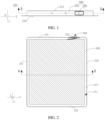
- FIG. 2 is a schematic structural diagram of FIG. 1 sectioned along a line AA.
- An electrochemical device 100 according to an embodiment of this application includes an electrode assembly 200 and a housing 300.
- An accommodation cavity 311 is formed in the housing 300.
- the electrode assembly 200 is accommodated in the accommodation cavity 311.
- the electrode assembly 200 is electrically connected to the housing 300.
- the electrode assembly 200 includes a first electrode plate 201, a second electrode plate 202, and a separator 203.
- the separator 203 is disposed between the first electrode plate 201 and the second electrode plate 202.
- the first electrode plate 201 and the second electrode plate 202 are of different polarities.
- the separator 203 is configured to reduce the risk of a short-circuit between the first electrode plate 201 and the second electrode plate 202.
- the electrode assembly 200 may assume a structure that is at least one of a jelly-roll structure or a stacked structure. As an example, in one circumstance, as shown in FIG.
- the first electrode plate 201, the second electrode plate 202, and the separator 203 are stacked and wound to form a jelly-roll structure.
- the plurality of first electrode plates 201, the plurality of second electrode plates 202, and the plurality of separators 203 are stacked along a thickness direction of the separator 203.
- a plurality of first electrode plates 201 of the same polarity are connected to each other.
- a plurality of second electrode plates 202 of the same polarity are connected to each other, so as to form a stacked structure.
- the thickness direction of the separator 203 is the thickness direction of the electrode assembly 200.
- the thickness direction of the electrode assembly 200 may be the same as a thickness direction Z of the housing 300.
- the electrode assembly 200 may assume a jelly-roll structure or a stacked structure.
- the thickness direction of the electrode assembly 200 may be different from the thickness direction Z of the housing 300.
- the thickness direction of the electrode assembly 200 is perpendicular to the thickness direction Z of the housing 300. In this case, the electrode assembly 200 assumes a stacked structure.
- FIG. 6 is a schematic diagram of a part of the housing 300
- FIG. 7 is a schematic diagram of a part of FIG. 2
- the housing 300 includes a first housing 310 and an electrode post assembly 320.
- An accommodation cavity 311 is formed in the first housing 310.
- a through mounting hole 312 is created on the first housing.
- the mounting hole 312 communicates with the accommodation cavity 311.
- the electrode post assembly 320 is mounted to the first housing 310 and seals the mounting hole 312 to reduce the risk of leaking the electrolyte solution in the accommodation cavity 311 out of the first housing 310 through the mounting hole 312.
- the first housing 310 may be made of a metal material or an alloy material.
- the first housing 310 When the first housing 310 is connected to a positive electrode, the first housing 310 may be an aluminum housing or an aluminum alloy housing.
- the aluminum alloy housing includes Al, and further includes one or more of Mn, Cr, Ni, Co, Cu, Fe, Mg, Si, Ti, V, or Zn, thereby reducing the risk of the first housing 310 being corroded by the electrolyte solution.
- the first housing 310 when the first housing 310 is connected to a negative electrode, the first housing 310 may be a steel housing.
- the steel housing includes Fe and C, and the steel housing may further include one or more of Ni, Co, Al, Mn, Cr, Cu, Mg, Mo, S, Si, Ti, V, Pb, Sb, N, or P, thereby reducing the risk of the first housing 310 being corroded by the electrolyte solution.
- a nickel (Ni) layer may be disposed on a surface of the first housing 310, the surface being oriented toward the electrode assembly 200, thereby further reducing the risk of the first housing 310 being corroded by the electrolyte solution.
- a nickel (Ni) layer may be disposed on a surface of the first housing 310, the surface being oriented back from the electrode assembly 200, thereby reducing the risk of the first housing 310 being corroded by the external environment.
- the first housing 310 may be made of an insulating material.
- two electrode post assemblies 320 may be mounted on the first housing 310. One of the electrode post assemblies 320 is electrically connected to the first electrode plate 201, and the other electrode post assembly 320 is electrically connected to the second electrode plate 202.
- the first housing 310 includes a first side plate 313, a second side plate 314, a third side plate 315, a fourth side plate 316, and a first plate 317 that are connected.
- the first side plate 313, the second side plate 314, the third side plate 315, and the fourth side plate 316 are all connected to the same surface of the first plate 317, and close in to form an accommodation cavity 311.
- the first side plate 313 is opposite to the second side plate 314, and the third side plate 315 is opposite to the fourth side plate 316.
- a mounting hole 312 is created on any one of the first side plate 313, the second side plate 314, the third side plate 315, or the fourth side plate 316.
- first side plate 313, the second side plate 314, the third side plate 315, the fourth side plate 316, and the first plate 317 may be made in one piece directly by die-casting or sheet metal stamping or other means, or may be made by injection molding, or may be made in other manners.
- the manufacturing manner is not limited to the examples mentioned herein, but may are selected depending on the material of the first housing 310.
- the first housing 310 further includes a second plate 318.
- the first side plate 313, the second side plate 314, the third side plate 315, and the fourth side plate 316 are all connected to the second plate 318.
- the electrode assembly 200 may be loaded into the accommodation cavity 311, and then the second plate 318 may be connected to the first side plate 313, the second side plate 314, the third side plate 315, and the fourth side plate 316, thereby encapsulating the electrode assembly 200 in the first housing 310.
- a part of the housing, in which the accommodation cavity 311 is formed may be made by stamping a sheet material.
- the second plate 318 covers the accommodation cavity 311.
- the first side plate 313, the second side plate 314, the third side plate 315, and the fourth side plate 316 are all connected to the second plate 318.
- the structure of the electrochemical device 100 of this application is further elaborated below by using an example in which a mounting hole 312 is created on the first side plate 313.
- the electrode post assembly 320 includes a rivet 321, a first gasket 322, and a second gasket 323. Both the first gasket 322 and the second gasket 323 are mounted to the rivet 321.
- the rivet 321 is connected to the electrode assembly 200, so that the rivet 321 can serve as one of the electrodes of the electrochemical device 100.
- the rivet 321 includes a shaft portion 3211, a first end portion 3212, and a second end portion 3213.
- the shaft portion 3211 passes through the mounting hole 312.
- the first end portion 3212 is located at one end of the shaft portion 3211, and the second end portion 3213 is located at another end of the shaft portion 3211.
- the projection of the shaft portion 3211 is located inside the projection of the first end portion 3212 and the projection of the second end portion 3213.
- the first direction X is an axial extension direction of the shaft portion 3211.
- the first direction X is perpendicular to the thickness direction Z of the housing 300. It is defined that a direction perpendicular to both the first direction X and the thickness direction Z of the housing 300 is a second direction Y.
- the first gasket 322 surround the shaft portion 3211. At least a part of the first gasket 322 is disposed between the first end portion 3212 and the first side plate 313 in the first direction X.
- the second gasket 323 surround the shaft portion 3211. The second gasket 323 is disposed between the second end portion 3213 and the first side plate 313 in the first direction X. Understandably, one of the first end portion 3212 or the second end portion 3213 needs to be disposed inside the accommodation cavity 311, and the other needs to be disposed outside the first housing 310. The specific arrangement depends on actual needs.
- first end portion 3212 is located inside the first accommodation cavity 311 and the second end portion 3213 is located outside the first housing 310.
- the rivet 321 is formed by performing a riveting process on the rivet feedstock 321'.
- FIG. 8 is a schematic diagram before the rivet feedstock 321' is subjected to a riveting process.
- the rivet feedstock 321' includes a countersink 3211' and a connecting portion 3212' connected to the countersink 3211'.
- the projection of the connecting portion 3212' in the first direction X is located inside the projection of the countersink 3211'.
- An end of the connecting portion 3212', which is away from the countersink 3211', is deformed by pressure after passing through the mounting hole 312, so that a shaft diameter at this end expands and deforms to form the rivet 321 shown in FIG. 7 .
- the countersink 3211' forms a first end portion 3212 after being deformed under pressure.
- An end of the connecting portion 3212' which is away from the countersink 3211', forms a second end portion 3213 after being deformed under pressure.
- the part located between the countersink 3211' and the first housing 310 is subjected to a squeezing force, that is, the first gasket 322 is squeezed, thereby forming a sealed region at the mounting hole 312, and in turn, reducing the risk of leaking the electrolyte solution out of the first housing 310 through the mounting hole 312.
- the compression force of the first gasket 322 and the second gasket 323 is primarily provided by the deformation of the end portion of the rivet feedstock 321' under pressure. Regions on the first gasket 322 and the second gasket 323, which are close to the shaft portion 3211 of the rivet 321, are subjected to a large force. Regions on the first gasket 322 and the second gasket 323, which are away from the shaft portion 3211 of the rivet 321, are subjected to a small force. A part of the first gasket 322 and a part of the second gasket 323, which are close to the shaft portion 3211, are compressed to a high degree.
- a gap exists at a sealing interface between the first gasket 322 and the first side plate 313, and a sealing interface between the second gasket 323 and the first side plate, thereby reducing the sealing effect of the sealed region, posing a risk that the electrolyte solution leaks out of the first housing 310 through the sealed region, and impairing the safety of the electrochemical device 100.
- FIG. 9 is a cross-sectional view when the electrode assembly 320 is mounted to the first housing 310 according to an embodiment
- FIG. 10 is a schematic diagram before a rivet 321 in the electrode post assembly 320 is subjected to a riveting process
- FIG. 11 is a schematic diagram of change of the structure between the rivet 321 and the first housing 310 during riveting
- FIG. 12 is a schematic diagram of the structure between the rivet 321 and the first housing 310 after completion of a riveting process.
- the electrode post assembly 320 further includes a pressing piece 324 in addition to the rivet 321, the first gasket 322, and the second gasket 323.
- the pressing piece 324 of the electrode post assembly 320 is disposed around the shaft portion 3211, and located between the first end portion 3212 and the first gasket 322. Viewed along the first direction X, the projection of the pressing piece 324 is located inside the projection of the first end portion 3212. That is, the area of the surface of the pressing piece 324 is less than the area of the surface of the first end portion 3212.
- the pressing piece 324 disposed around the shaft portion 3211 may be understood to mean that the pressing piece 324 surround the shaft portion 3211 and the pressing piece 324 is in contact with or in clearance fit with the surface of the shaft portion 3211.
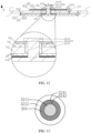
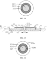
- FIG. 13 is a top view when the pressing piece 324 is assembled to the shaft portion 3211.
- the pressing piece 324 includes a first surface 3241 and a second surface 3242 connected to the first surface 3241.
- the first surface 3241 abuts the first end portion 3212.
- the second surface 3242 is an inner wall face of the pressing piece 324 toward the shaft portion 3211.
- the second surface 3242 is in contact or out of contact with the surface of the shaft portion 3211.
- FIG. 13 is a top view when the pressing piece 324 is assembled to the shaft portion 3211.
- the pressing piece 324 includes a first surface 3241 and a second surface 3242 connected to the first surface 3241.
- the first surface 3241 abuts the first end portion 3212.
- the second surface 3242 is an inner wall face of the
- the second surface 3242 of the pressing piece 324 is in contact with the shaft portion 3211, thereby improving the hermeticity between the pressing piece 324 and the shaft portion 3211, and in turn, reducing the electrolyte leakage risk of the electrochemical device 100.
- the first end portion 3212 is subjected to the force of the shaft portion 3211, and therefore, presses against the pressing piece 324 and fits the surface of the first gasket 322; and the second end portion 3213 is subjected to the force of the shaft portion 3211, and therefore, presses against the second gasket 323 and fits the first housing 310.
- overlapping parts of the pressing piece 324, the first end portion 3212, the first gasket 322, the first housing 310, the second gasket 323, and the second end portion 3213 form a sealed region on one side of the mounting hole 312.
- the technical solution in this embodiment lets the first end portion 3212 indirectly press against the first gasket 322 through the pressing piece 324.
- the pressure exerted by the pressing piece 324 on the first gasket 322 is greater than the pressure exerted when the first end portion 3212 directly presses against the first gasket 322. This increases the degree of deformation of a part of the first gasket 322, the part being pressed by the pressing piece 324.
- the first gasket 322 abuts the pressing piece 324 more closely, thereby improving the hermeticity at the contact position between the first gasket 322 and the pressing piece 324. Therefore, when applied to the first housing 310, the electrode post assembly 320 of this embodiment improves the hermeticity of the sealed region at the mounting hole 312, and improves the safety of the electrochemical device 100. In addition, assuming that the same sealing effect is achieved, a pressing piece 324 is added in this application so that the first end portion 3212 indirectly presses against the first gasket 322.
- this application increases the overall thickness of the part between the first end portion 3212 and the second end portion 3213.
- the amount of deformation required for deforming the shaft portion 3211 of the rivet 321 in the first direction X becomes smaller, thereby reducing the risk that the edge part of the first gasket 322 is warped against the first housing 310 in the first direction X, and improving the hermeticity of the electrochemical device 100 at the mounting hole 312.
- the overlapping parts of the pressing piece 324, the first end portion 3212, the first gasket 322, the first housing 310, the second gasket 323, and the second end portion 3213 in the first direction X form a sealed region at the mounting hole 312.
- the non-overlapping parts of the first end portion 3212 and the pressing piece 324 are in clearance fit with the first gasket 322, and the clearance does not affect the hermeticity of the sealed region.
- the first gasket 322 is made of a material of insulating properties, for example, polyethylene, polypropylene, polytetrafluoroethylene, or fluororubber; Alternatively, the first gasket 322 may be made of a mixture of a variety of other known materials, such as a mixture of at least two of polyethylene, polypropylene, polytetrafluoroethylene, or fluororubber.
- the thickness of the first gasket 322 along the first direction X is T 1 mm, satisfying: 0.1 ⁇ T 1 ⁇ 5.
- the thickness T 1 of the first gasket 322 in the first direction X is appropriate, thereby reducing the risk that the first gasket 322 is unduly thin and crushed during riveting, and also reducing the footprint of the first gasket 322.
- the first gasket 322 is made of a plastic material.
- FIG. 15 is a schematic diagram of a partial structure in FIG. 1 sectioned along a line AA, and FIG. 15 hides the pressing piece 324.
- An accommodation trough 3221 is created on the first gasket 322.
- the shaft portion 3211 runs through the bottom of the accommodation trough 3221.
- the pressing piece 324 is at least partially accommodated in the accommodation trough 3221. That is, the thickness of the pressing piece 324 is greater than the depth of the bottom of the accommodation trough 3221. Viewed along the first direction X, the projection of the pressing piece 324 is located inside the accommodation trough 3221.
- the part of the first housing 310, the part of the first gasket 322, and the part of the first end portion 3212, which overlap the pressing piece 324 in the first direction X, form a sealed region, thereby reducing the risk that the unpressed part of the first gasket 322 is warped against the first housing 310 and leads to a decrease in the hermeticity, and in turn, improving the safety of the electrochemical device 100.
- the first gasket 322 is made of an elastic material.
- the pressing piece 324 is stressed by the rivet 321 in a riveting process to squeeze the first gasket 322, the first gasket 322 is deformed under pressure to form a recessed region. As shown in FIG. 12 , at least a part of the pressing piece 324 is embedded into the recessed region of the first gasket 322. In other words, the first gasket 322 is deformed by the squeezing action of the pressing piece 324, so that the first gasket 322 forms a space available for being filled with the pressing piece 324.
- the first gasket 322 provides the filling space for the pressing piece 324 by compressing a part of the material, but does not provide the filling space for the pressing piece 324 by cutting away a part of the material. Therefore, compared to the technical solution that provides the filling space for the pressing piece 324 by creating a groove, the degree of compression on the first gasket 322 in this embodiment is higher, thereby increasing the hermeticity of the overlapping parts and improving the safety of the electrochemical device 100.
- the overlapping parts are a part of the first housing 310, a part of the first gasket 322, and a part of the first end portion 3212, and overlap the pressing piece 324 in the first direction X.
- the first gasket 322 includes a first body 3223 and a first flange 3224.
- the first body 3223 surround the shaft portion 3211 and disposed between the first end portion 3212 and the first housing 310.
- the first flange 3224 is formed by extending an edge of the first body 3223 away from the second gasket 323.
- the first body 3223 and the first flange 3224 define a first groove 3225.
- the first flange 3224 reduces the impact caused by free electrolyte solution on the first end portion 3212 and the edge of the first gasket 322, and reduces the possibility that the electrolyte solution enters the clearance between the first end portion 3212 and the pressing piece 324 from the edge of the first body 3223, thereby reducing the risk that the electrolyte solution leaks out of the first housing 310 along the contact surface between the first gasket 322 and the pressing piece 324, and along the contact surface between the first end portion 3212 and the pressing piece 324.
- this reduces the risk of swelling when the first gasket 322 is made of a polymer material, and improves the hermeticity at the mounting hole 312.
- the first flange 3224 reduces the possibility of contact between the first end portion 3212 and the first housing 310, and reduces the risk of a short-circuit between the first end portion 3212 and the first housing 310.
- both the pressing piece 324 and the first end portion 3212 are disposed in the first groove 3225, thereby shortening the length of the electrode post assembly 320 in the first direction X without impairing the hermeticity, and in turn, improving the hermeticity at the mounting hole 312.
- the first gasket 322 further includes an extension portion 3226.
- the extension portion 3226 is formed by extending the first body 3223 toward the second gasket 323.
- the extension portion 3226 is disposed between the wall of the mounting hole 312 and the shaft portion 3211. Understandably, after completion of the riveting process, the shaft diameter of the shaft portion 3211 becomes larger, and the extension portion 3226 is squeezed by the shaft portion 3211, so that the extension portion 3226 can fill the clearance between the shaft portion 3211 and the mounting hole 312, thereby improving the hermeticity at the mounting hole 312.
- the shape of the first groove 3225 fits the first end portion 3212, thereby facilitating smoother embedding of the first end portion 3212 into the first groove 3225, and improving the hermeticity of the electrochemical device 100.
- the first end portion 3212 is in a cylindrical shape
- the first groove 3225 is in a circular groove shape
- the first end portion 3212 is in a square block shape
- the first groove 3225 is in a square shape.
- the second gasket 323 is also made of a material of insulating properties, for example, polyethylene, polypropylene, polytetrafluoroethylene, or fluororubber; Alternatively, the second gasket 323 may be made of a mixture of a variety of other known materials, such as a mixture of at least two of polyethylene, polypropylene, polytetrafluoroethylene, or fluororubber.
- the thickness of the second gasket 323 along the first direction X is T 2 mm, satisfying: 0 ⁇ T 2 ⁇ 5.
- the thickness T 2 of the second gasket 323 in the first direction X is appropriate, thereby reducing the risk that the second gasket 323 is unduly thin and crushed during riveting, and also reducing the footprint of the second gasket 323.
- the second gasket 323 includes a second body 3231 and a second flange 3232.
- the second body 3231 surround the shaft portion 3211 and disposed between the second end portion 3213 and the first housing 310 to separate the second end portion 3213 from the first housing 310.
- the second flange 3232 is formed by extending an edge of the second body 3231 away from the first gasket 322.
- the second body 3231 and the second flange 3232 define a second groove 3233.
- the pressing piece 324 may be made of an insulating material or a metal material, depending on actual needs.
- the hardness of the pressing piece 324 needs to be greater than the hardness of the first gasket 322 so as to reduce the risk of deforming the pressing piece 324 but without deforming the first gasket 322 when the first end portion 3212 presses against the pressing piece 324 to exert a pressure on the first gasket 322.
- the pressing piece 324 is made of a metal material, the material of the pressing piece 324 needs to avoid a redox reaction with the rivet 321 at a high potential, so as to reduce the risk that the hermeticity of the electrochemical device 100 is reduced by the reaction between the pressing piece 324 and the rivet 321.
- the metal may be aluminum, copper, aluminum alloy, or copper alloy.
- the hardness of the pressing piece 324 and the hardness of the first gasket 322 may be measured and compared by using an existing hardness measurement method, such as a Vickers hardness measurement method suitable for measuring various types of materials, or a Rockwell hardness measurement method for measuring the hardness of relatively soft materials such as steel and non-ferrous materials.
- the hardness measurement method may be selected depending on the materials of the pressing piece 324 and the first gasket 322.
- the pressing piece 324 is in a closed shape around the shaft portion 3211.
- the shape of the pressing piece 324 is a block with a through-hole, for example, an annular block, a square block with a through-hole, or another shape, as long as the pressing piece can be disposed around the shaft portion 3211.
- the pressing piece 324 may be formed by splicing two parts.
- the pressing piece 324 may include a first semi-circular block 324a and a second semi-circular block 324b.
- a protruding portion is disposed on one of the first semi-circular block 324a or the second semi-circular block 324b, and a recess is created on the other of the first semi-circular block or the second semi-circular block.
- the protruding portion can fit into the recess so that the first semi-circular block and the second semi-circular block are spliced to form the pressing piece 324.
- the pressing piece 324 may be molded in one piece, for example, by an injection molding or die-casting process. The pressing piece 324 molded in one piece increases the hermeticity of the electrochemical device 100, and improves the safety of the electrochemical device 100.
- the projection of the edge of the second end portion 3213 is located inside the projection of the pressing piece 324.
- the edge of the second end portion 3213 does not extend beyond the edge of the pressing piece 324, thereby making it convenient for the second end portion 3213 to be compressed by the pressing piece 324, increasing the area on which the first gasket 322 is compressed by the second end portion 3213, and in turn, increasing the degree of compression on the first gasket 322, and improving the hermeticity of the electrochemical device 100.
- a projected area of the first end portion 3212 is S 1
- a projected area of the shaft portion 3211 is S 3
- a projected area of the pressing piece 324 is S 4 , satisfying: S 4 /(S 1 - S 3 ) ⁇ 1/2.
- a projected area of the second end portion 3213 is S 2
- the projected area of the shaft portion 3211 is S 3
- the projected area of the pressing piece 324 is S 4 , satisfying: S 4 /(S 2 - S 3 ) ⁇ 1/2.
- the shaft portion 3211 is cylindrical, and the diameter of the shaft portion 3211 is D mm, satisfying: 0.3 ⁇ D ⁇ 5.
- the cross-sectional area of the shaft portion 3211 is appropriate, thereby reducing the risk that the shaft portion 3211 occupies an excessive area of the first housing 310, lowering the dimensional requirement on the shaft portion 3211 at the mounting hole 312 of the first housing 310, reducing the risk that the material of the first housing 310 is excessively cut away at the mounting hole 312, increasing the strength of the first housing 310, and ensuring a high current-carrying capacity of the rivet 321.
- the diameter of the shaft portion 3211 may be measured by a measurement tool such as a vernier caliper.
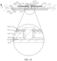
- the pressing piece 324 and the first end portion 3212 are a one-piece member.
- a boss 32121 is directly disposed on a side of the first end portion 3212, the side being connected to the shaft portion 3211.
- the pressing piece 324 may be canceled, and the boss 32121 directly serves as a pressing piece 324, thereby also achieving the sealing effect for the sealed region, reducing the operations required for mounting the electrode post assembly 320 to the first housing 310, and improving the assembling efficiency of the electrochemical device 100.
- the pressing piece 324 and the first gasket 322 are a one-piece member.
- a bulge 3227 protruding beyond the surface is directly disposed on a side of the first gasket 322, the side being oriented toward the first end portion 3212.
- the bulge 3227 serves as a pressing piece 324.
- the electrode post assembly 320 further includes a third gasket 325.
- the third gasket 325 surround the shaft portion 3211, and disposed between the second end portion 3213 and the second gasket 323. Viewed along the first direction X, the projection of the third gasket 325 is located inside the projection of the second gasket 323. Moreover, at least a part of the third gasket 325 is located in the second groove 3233. With the third gasket 325 disposed, the second end portion 3213 indirectly presses the second gasket 323 through the third gasket 325.
- the technical solution hereof reduces the degree of deformation of the pressed second gasket 323 and reduces the risk that the edge part of the second gasket 323 is warped against the first housing 310.
- the risk of contact between the second end portion 3213 and the first housing 310 is reduced, thereby reducing the risk of a short-circuit of the electrochemical device 100, and improving the safety of the electrochemical device 100.
- the projection of the pressing piece 324 is located inside the projection of the third gasket 325.
- the third gasket 325 is made of a metal material. Such an arrangement reduces the possibility that excessive stress is exerted by the second end portion 3213 on the second gasket 323 in the sealing process and impairs the sealing effect. Such an arrangement also provides a position at which the stress works in the sealing process of the second end portion 3213.
- the third gasket is made of a material including aluminum, copper, aluminum alloy, or copper alloy.
- the specific number of electrode post assemblies 320 is set according to actual needs.
- the number of electrode post assemblies 320 is one, and the electrode post assembly 320 is mounted to the first housing 310.
- the first electrode plate 201 is connected to the rivet 321, and the second electrode plate 202 is electrically connected to the first housing 310.
- the electrode post assembly 320 and the first housing 310 one serves as a positive electrode of the electrochemical device 100, and the other serves as a negative electrode.
- the number of electrode post assemblies 320 is two, and both electrode post assemblies 320 are mounted to the first housing 310.
- the two electrode post assemblies 320 may be mounted to the same side or different sides of the first housing 310.
- the first electrode plate 201 is connected to the rivet 321 of one electrode post assembly 320, and the second electrode plate 202 is connected to the rivet 321 of the other electrode post assembly 320.
- the two electrode post assemblies 320 serve as a positive electrode and a negative electrode of the electrochemical device 100 respectively.
- An embodiment of this application provides an electrochemical device 100, including an electrode assembly 200 and a housing 300.
- An accommodation cavity 311 is formed in the housing 300.
- the electrode assembly 200 is accommodated in the accommodation cavity 311.
- the housing 300 includes a first housing 310 and an electrode post assembly 320.
- the electrode post assembly 320 includes a rivet 321, a first gasket 322, a second gasket 323, and a pressing piece 324.
- the rivet 321 includes a shaft portion 3211, a first end portion 3212, and a second end portion 3213.
- the first end portion 3212 When the rivet 321 is riveted to the first housing 310, the first end portion 3212 is subjected to the force of the shaft portion 3211, and therefore, presses against the pressing piece 324 and fits the surface of the first gasket 322; and the second end portion 3213 is subjected to the force of the shaft portion 3211, and therefore, presses against the second gasket 323 and fits the first housing 310.
- overlapping parts of the pressing piece 324, the first end portion 3212, the first gasket 322, the first housing 310, the second gasket 323, and the second end portion 3213 form a sealed region on one side of the mounting hole 312.
- the electrode post assembly 320 of this embodiment improves the hermeticity of the sealed region at the mounting hole 312, and improves the safety of the electrochemical device 100.
- the electronic device 500 includes, but is not limited to, a notebook computer, pen-inputting computer, mobile computer, e-book player, portable phone, portable fax machine, portable photocopier, portable printer, stereo headset, video recorder, liquid crystal display television set, handheld cleaner, portable CD player, mini CD-ROM, transceiver, electronic notepad, calculator, memory card, portable voice recorder, radio, backup power supply, motor, automobile, motorcycle, power-assisted bicycle, bicycle, lighting appliance, toy, game console, watch, electric tool, flashlight, camera, large household battery, lithium-ion capacitor, and the like.
- Another embodiment of this application further provides a method for manufacturing an electrochemical device.
- the method includes the following steps: Step S201: Preparing a housing;
- the structure of the housing 300 is the same as that of the housing 300 mentioned in the preceding embodiment, and specifically, includes a first housing 310 and an electrode post assembly 320.
- the first housing 310 includes a first side plate 313, a second side plate 314, a third side plate 315, a fourth side plate 316, a first plate 317, and a second plate 318.
- a mounting hole 312 is created on the first housing 310.
- the electrode post assembly 320 is mounted to the mounting hole 312.
- a process of preparing the housing includes the following steps: Step S2011: Providing an electrode post assembly feedstock and the first housing.
- the electrode post assembly feedstock includes the rivet feedstock 321' mentioned in the preceding embodiment, a first gasket 322, a second gasket 323, and a pressing piece 324.
- the first gasket 322, the second gasket 323, and the pressing piece 324 are all mounted to the rivet feedstock 321'.
- Step S2012 Mounting the electrode post assembly feedstock to the first housing, and performing a riveting process on the electrode post assembly feedstock, so that one end of the rivet feedstock 321' forms a second end portion 3213 to obtain an electrode post assembly 320, during which the pressing piece 324 squeezes the first gasket 322 by being stressed in the riveting process.
- Step S202 Mounting the electrode assembly 200 into the housing 300.
- first gasket 322 is deformed under pressure to form a recessed region, so that at least a part of the pressing piece 324 is embedded into the recessed region of the first gasket 322.
- the electrochemical device 100 manufactured by using the housing 300 is of high hermeticity, and the safety of the electrochemical device 100 is improved.
- the electrode post assembly feedstock further includes a third gasket 325.
- the third gasket 325 is located on the second gasket 323, and mounted to the rivet feedstock 321'. During riveting of the rivet feedstock 321', stress is applied to the second gasket 323 through the third gasket 325. After the rivet feedstock 321' is riveted, at least a part of the third gasket 325 is located between the second end portion 3213 and the second gasket 323. With the third gasket 325 disposed, the second end portion 3213 indirectly presses the second gasket 323 through the third gasket 325.
- the technical solution hereof reduces the degree of deformation of the pressed second gasket 323 and reduces the risk that the edge part of the second gasket 323 is warped against the first housing 310.
Landscapes
- Chemical & Material Sciences (AREA)
- Chemical Kinetics & Catalysis (AREA)
- Electrochemistry (AREA)
- General Chemical & Material Sciences (AREA)
- Engineering & Computer Science (AREA)
- Manufacturing & Machinery (AREA)
- Sealing Battery Cases Or Jackets (AREA)
- Connection Of Batteries Or Terminals (AREA)
- Electric Double-Layer Capacitors Or The Like (AREA)
Abstract
Description
- Some embodiments of this application relate to the technical field of energy storage, and in particular, to a housing, an electrochemical device and a manufacturing method thereof, and an electronic device.
- An electrochemical device is a device that converts external energy into electrical energy and internally stores the electrical energy so that the electrical energy is readily available to an electronic device such as a mobile phone, a tablet computer, or a laptop computer. Generally, an electrochemical device includes a housing and an electrode assembly. An accommodation cavity is formed in the housing. The electrode assembly is accommodated in the accommodation cavity. The electrode assembly includes a first electrode plate, a separator, and a second electrode plate. The separator is disposed between the first electrode plate and the second electrode plate. The first electrode plate and the second electrode plate are of different polarities.
- To meet the needs of different mounting environments, a mounting hole needs to be created on the housing of some electrochemical devices, and an electrode post needs to be mounted at the mounting hole. The electrode post serves as one of electrodes of the electrochemical device. However, when the mounting hole is created on the housing to mount the electrode post, a gap exists between the electrode post and the housing. Through the gap, an electrolyte solution loaded in the housing is prone to leak to the outside. Therefore, it is necessary to design an electrode post assembly hermetically mounted to the housing, so as to reduce the risk of electrolyte leakage of the electrochemical device.
- An objective of this application is to provide a housing, an electrochemical device and a manufacturing method thereof, and an electronic device to reduce the electrolyte leakage risk of the electrochemical device.
- To achieve the above objective, this application discloses the following technical solution:
A housing is disclosed, including a first housing and an electrode post assembly. An accommodation cavity is formed in the first housing. A through mounting hole is created on the first housing. The mounting hole communicates with the accommodation cavity. The electrode post assembly includes a rivet, a first gasket, a second gasket, and a pressing piece. The rivet includes a shaft portion, a first end portion, and a second end portion. The shaft portion passes through the mounting hole. The first end portion is connected to one end of the shaft portion, and the second end portion is connected to another end of the shaft portion. A projection of the shaft portion is located inside a projection of the first end portion and the second end portion in a first direction. The first direction is an axial extension direction of the shaft portion. The first gasket surround the shaft portion. At least a part of the first gasket is disposed between the first end portion and the first housing in the first direction. The second gasket surround the shaft portion. At least a part of the second gasket is disposed between the second end portion and the first housing in the first direction. The pressing piece is disposed around the shaft portion. In the first direction, the pressing piece is disposed between the first end portion and the first gasket, and a projection of the pressing piece is located inside the projection of the first end portion. The first end portion coordinates with the second end portion to compress the first gasket and the second gasket to seal the through mounting hole. - The electrode post assembly in the housing provided in this application includes a pressing piece in addition to the rivet, the first gasket, and the second gasket. Along the first direction, the projection of the pressing piece is located inside the projection of the first end portion. In other words, a cross-sectional profile of the pressing piece is smaller than a cross-sectional profile of the first end portion. In this way, the first end portion presses against the pressing piece in such a way that the pressure exerted by the pressing piece on the first gasket is greater than the pressure exerted when the first end portion directly presses against the first gasket, thereby leading to a higher degree of deformation of the pressed part at which the first gasket touches the pressing piece. Due to the tendency of the first gasket to restore the original shape, the first gasket presses against the pressing piece more closely, thereby improving the hermeticity at the position of contact between the first gasket and the pressing piece. Therefore, the housing provided in this application is of high hermeticity at the mounting hole, and may reduce the risk of sealing failure between the first end portion and the first gasket. In addition, a pressing piece is added in this application so that the first end portion indirectly presses against the first gasket. Compared with the technical solution in which the first end portion directly presses against the first gasket, this application increases the overall thickness of the part between the first end portion and the second end portion. The amount of deformation required for deforming the shaft portion of the rivet in the first direction becomes smaller, thereby reducing the risk that the first gasket is warped against the first housing in the first direction, and improving the hermeticity of the electrochemical device at the mounting hole.
- In some embodiments, viewed along the first direction, the pressing piece is in a closed shape around the shaft portion. This reduces the risk that the electrolyte solution enters the mounting hole through the pressing piece, and improves the hermeticity of the first housing.
- In some embodiments, the pressing piece and the first end portion are a one-piece member. This may save the step of mounting the pressing piece, and save the time required for assembling the housing.
- In some embodiments, the pressing piece and the first gasket are a one-piece member. This may save the step of mounting the pressing piece, and save the time required for assembling the housing.
- In some embodiments, in the first direction, a projection of an edge of the second end portion is located inside the projection of the pressing piece. In this way, the second end portion is facilitated to receive the pressure exerted by the pressing piece, thereby increasing the degree of compression on the gasket and improving the hermeticity of the first housing at the mounting hole.
- In some embodiments, the second end portion is formed by a riveting process. This facilitates the riveting process and disperses the riveting force through the pressing piece, thereby enhancing the sealing effect and reducing the risk of gasket warping.
- In some embodiments, the pressing piece includes a first surface and a second surface connected to the first surface. The first surface is adjacent to the second surface. The first surface abuts the first end portion. The second surface is in contact with a surface of the shaft portion. This improves the hermeticity between the pressing piece and the shaft portion, thereby reducing the electrolyte leakage risk of the electrochemical device.
- In some embodiments, hardness of the pressing piece is greater than hardness of the first gasket. This reduces the risk that the pressing piece is deformed but without deforming the first gasket in the riveting process, and improves the hermeticity between the first end portion and the first gasket.
- In some embodiments, viewed along the first direction, a projected area of the first end portion is S1, a projected area of the shaft portion is S3, and a projected area of the pressing piece is S4, satisfying: S4/(S1 - S3) ≤ 1/2. In this way, an edge part of the pressing piece, which is away from the shaft portion, receives an appropriate force of the rivet, and the first gasket, the pressing piece, and the first end portion abut each other closely, thereby improving the hermeticity of the electrode post assembly at the mounting hole.
- In some embodiments, viewed along the first direction, a projected area of the second end portion is S2, a projected area of the shaft portion is S3, and a projected area of the pressing piece is S4, satisfying: S4/(S2 - S3) ≤ 1/2. In this way, an edge part of the pressing piece, which is away from the shaft portion, receives an appropriate force of the rivet, and the first gasket, the pressing piece, and the first end portion abut each other closely, thereby improving the hermeticity of the electrode post assembly at the mounting hole.
- In some embodiments, the pressing piece is stressed by the rivet in a riveting process to squeeze the first gasket so that the first gasket is deformed under pressure to form a recessed region, and so that at least a part of the pressing piece is embedded into the recessed region of the first gasket. This increases the degree of compression on the first gasket by the pressing piece, and improves the hermeticity of the first housing at the mounting hole.
- In some embodiments, the shaft portion is cylindrical, and a diameter of the shaft portion is D mm, satisfying: 0.3 ≤ D ≤ 5. When the diameter of the shaft portion falls within this range, an appropriate current-carrying capacity may be provided. At the same time, the dimensional requirements of the shaft portion at the mounting hole of the first housing are lowered, thereby reducing the risk that the amount of material of the first housing at the mounting hole is excessively cut away, and increasing the strength of the first housing.
- In some embodiments, the first gasket includes a first body and a first flange. The first body surround the shaft portion and disposed between the first end portion and the first housing. The first flange is formed by extending an edge of the first body away from the second gasket. The first body and the first flange define a first groove.
- On the one hand, the first flange reduces the impact caused by free electrolyte solution on the first end portion and the edge of the first gasket, and reduces the possibility that the electrolyte solution enters the clearance between the first end portion and the pressing piece from the edge of the first body, thereby reducing the risk that the electrolyte solution leaks out of the first housing along the contact surface between the first gasket and the pressing piece, and along the contact surface between the first end portion and the pressing piece. On the other hand, this reduces the risk of swelling when the first gasket is made of a polymer material, and improves the hermeticity at the mounting hole. Moreover, the first flange reduces the possibility of contact between the first end portion and the first housing, and reduces the risk of a short-circuit between the first end portion and the first housing.
- In some embodiments, both the pressing piece and the first end portion are disposed in the first groove. In this way, high hermeticity is achieved. At the same time, the length of the electrode post assembly in the first direction is shortened, thereby improving the hermeticity at the mounting hole.
- In some embodiments, the electrode post assembly further includes a third gasket. The third gasket surround the shaft portion. At least a part of the third gasket is disposed between the second end portion and the second gasket in the first direction, and a projection of the third gasket is located inside a projection of the second gasket. With the third gasket disposed, the second end portion indirectly presses the second gasket through the third gasket. Compared to the technical solution in which the second end portion directly presses the second gasket, the technical solution hereof reduces the degree of deformation of the pressed second gasket and reduces the risk that the edge part of the second gasket is warped against the first housing.
- In some embodiments, the second gasket includes a second body and a second flange. The second body surround the shaft portion and disposed between the second end portion and the first housing to separate the second end portion from the first housing. The second flange is formed by extending an edge of the second body away from the first gasket. The second body and the second flange define a second groove. The third gasket is located in the second groove. The second flange reduces the risk of contact between the second end portion and the first housing, and reduces the risk of a short-circuit between the second end portion and the first housing.
- In some embodiments, in the first direction, the projection of the pressing piece is located inside a projection of the third gasket. Such an arrangement facilitates uniform transfer of the sealing force of the second end portion to the pressing piece, thereby improving the sealing effect.
- In some embodiments, the third gasket is made of a metal material. Such an arrangement reduces the possibility that excessive stress is exerted by the second end portion on the second gasket in the sealing process, and impairs the sealing effect. Such an arrangement also provides a position at which the stress works in the sealing process of the second end portion.
- In some embodiments, the thickness of the first gasket along the first direction is T1 mm, satisfying: 0.1 ≤ T1 ≤ 5; and the thickness of the second gasket along the first direction is T2 mm, satisfying: 0.1 ≤ T2 ≤ 5. With such settings, the thicknesses of the first gasket and the second gasket in the first direction are appropriate, thereby reducing the risk that the first gasket and the second gasket are unduly thin and crushed during riveting, and also reducing the footprint of the first gasket and the second gasket.
- In some embodiments, the first end portion is located inside the accommodation cavity, and the second end portion is located outside the accommodation cavity.
- In some embodiments, the first housing is made of a metal material. In some embodiments, the rivet is made of a material including aluminum, copper, aluminum alloy, or copper alloy. In some embodiments, the first gasket is made of a material including at least one of polyethylene, polypropylene, polytetrafluoroethylene, or fluororubber. In some embodiments, the second gasket is made of a material including at least one of polyethylene, polypropylene, polytetrafluoroethylene, or fluororubber. In some embodiments, the pressing piece is made of a metal material.
- To achieve the above objective, this application discloses the following technical solution:
An electrochemical device is disclosed, including the housing disclosed above, and an electrode assembly. The electrode assembly is located in the accommodation cavity. The electrode assembly is electrically connected to the rivet. In this way, the electrochemical device made by using the above housing is highly hermetic, and improves the safety of the electrochemical device. - In some embodiments, the first housing is a conductor. The first gasket and the second gasket are insulators. The electrode assembly includes a first electrode plate and a second electrode plate that are of opposite polarities. The first electrode plate is electrically connected to the rivet, and the second electrode plate is electrically connected to the first housing.
- To achieve the above objective, this application discloses the following technical solution:
A method for manufacturing the electrochemical device is disclosed, which is applied to the electrochemical device disclosed above. The method includes the following steps: preparing the housing; and mounting the electrode assembly into the housing. The step of preparing the housing includes: providing an electrode post assembly feedstock and the first housing; and mounting the electrode post assembly feedstock to the first housing, and performing a riveting process on the electrode post assembly feedstock to obtain the electrode post assembly, during which the pressing piece squeezes the first gasket by being stressed in the riveting process. - In some embodiments, the first gasket is deformed under pressure to form a recessed region, so that at least a part of the pressing piece is embedded into the recessed region of the first gasket.
- To achieve the objective hereof, this application discloses the following technical solution: an electronic device, including the electrochemical device disclosed above.
- One or more embodiments are described illustratively with reference to corresponding drawings. The illustrative description does not constitute any limitation on the embodiments. Components marked with the same reference numeral in the drawings represent similar components. Unless otherwise expressly specified, the drawings are not drawn to scale.
-
FIG. 1 is a top view of an electrochemical device according to an embodiment of this application; -
FIG. 2 is a schematic structural diagram ofFIG. 1 sectioned along a line AA according to an embodiment of this application; -
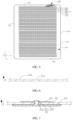
FIG. 3 is a schematic diagram of an electrode assembly shown inFIG. 2 sectioned along a line BB; -
FIG. 4 is another schematic diagram of an electrode assembly shown inFIG. 2 sectioned along a line BB; -
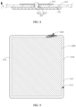
FIG. 5 is a schematic structural diagram ofFIG. 1 sectioned along a line AA according to another embodiment; -
FIG. 6 is a schematic structural diagram of a part of a first side plate shown inFIG. 5 ; -
FIG. 7 is a schematic diagram of a part of the structure shownFIG. 6 ; -
FIG. 8 is a schematic diagram before a rivet inFIG. 7 is subjected to a riveting process; -
FIG. 9 is a schematic structural diagram ofFIG. 1 sectioned along a line AA according to still another embodiment; -
FIG. 10 is a schematic diagram before a rivet is subjected to a riveting process; -
FIG. 11 is a schematic diagram of the rivet inFIG. 10 further stressed; -
FIG. 12 is a schematic diagram of the rivet inFIG. 11 after completion of a riveting process; -
FIG. 13 is a top view of assembling a pressing piece to a shaft portion according to an embodiment; -
FIG. 14 is a top view of assembling a pressing piece to a shaft portion according to another embodiment; -
FIG. 15 is a schematic diagram of another circumstance ofFIG. 12 andFIG. 15 hides a pressing piece and shows a first gasket in which an accommodation trough is provided; -
FIG. 16 is a top view of assembling a pressing piece to a shaft portion according to still another embodiment; -
FIG. 17 is a schematic diagram of projected areas of a first end portion, a second end portion, a pressing piece, and a shaft portion projected along a first direction; -
FIG. 18 is a schematic diagram when a pressing piece and a first end portion inFIG. 12 are a one-piece member; -
FIG. 19 is a schematic diagram when a pressing piece and a first gasket inFIG. 12 are a one-piece member; and -
FIG. 20 is a structural block diagram of an electronic device according to another embodiment of this application. - List of reference numerals: 100. electrochemical device; 200. electrode assembly; 300. housing; 311. accommodation cavity; 201. first electrode plate; 202. second electrode plate; 203. separator; 310. first housing; 320. electrode post assembly; 312. mounting hole; 313. first side plate; 314. second side plate; 315. third side plate; 316. fourth side plate; 317. first plate; 321. rivet; 322. first gasket; 323. second gasket; 324. pressing piece; 325. third gasket; 3211. shaft portion; 3212. first end portion; 3213. second end portion; 321'. rivet feedstock; 3221. accommodation trough; 3223. first body; 3224. first flange; 3225. first groove; 3231. second body; 3232. second flange; 3226. extension portion; 3227. bulge; 318. second plate; 32121. boss; 3233. second groove; 3241. first surface; 3242. second surface; 500. electronic device; 3211'. countersink; 3212'. connecting portion.
- For ease of understanding this application, the following describes this application in more detail with reference to drawings and specific embodiments. It is hereby noted that an element referred to herein as being "fixed to", "fastened to", or "mounted to" another element may be directly disposed on the other element, or may be fixed or fastened to the other element with one or more elements in between. An element referred to herein as "connected to" another element may be connected to the other element directly or with one or more elements in between. The terms "vertical", "horizontal", "left", "right", "in", "out" and other similar expressions used herein are merely for ease of description.
- Unless otherwise defined, all technical and scientific terms used herein bear the same meanings as what is normally understood by a person skilled in the technical field of this application. The terms used in the specification of this application are merely intended to describe specific embodiments but not to limit this application. The term "and/or" used herein is intended to include any and all combinations of one or more relevant items recited.
- In addition, to the extent that no mutual conflict occurs, the technical features described below in different embodiments of this application may be combined with each other.
- In this specification, the meanings of "mounting" or "installation" include fixing or confining an element or unit to a specific position or place by welding/soldering, screwing, snap-fit connection, bonding, or other means, where the element or unit may be held stationary in the specific position or place or may move within a limited range, and the element or unit may be detachable or undetachable after being fixed or confined to the specific position or place, without being limited in embodiments of this application.
- As shown in
FIG. 1 to FIG. 2, FIG. 2 is a schematic structural diagram ofFIG. 1 sectioned along a line AA. Anelectrochemical device 100 according to an embodiment of this application includes anelectrode assembly 200 and ahousing 300. Anaccommodation cavity 311 is formed in thehousing 300. Theelectrode assembly 200 is accommodated in theaccommodation cavity 311. Theelectrode assembly 200 is electrically connected to thehousing 300. - Referring to
FIG. 2 to FIG. 4 , theelectrode assembly 200 includes afirst electrode plate 201, asecond electrode plate 202, and aseparator 203. Theseparator 203 is disposed between thefirst electrode plate 201 and thesecond electrode plate 202. Thefirst electrode plate 201 and thesecond electrode plate 202 are of different polarities. Theseparator 203 is configured to reduce the risk of a short-circuit between thefirst electrode plate 201 and thesecond electrode plate 202. Theelectrode assembly 200 may assume a structure that is at least one of a jelly-roll structure or a stacked structure. As an example, in one circumstance, as shown inFIG. 3 , thefirst electrode plate 201, thesecond electrode plate 202, and theseparator 203 are stacked and wound to form a jelly-roll structure. In another circumstance, as shown inFIG. 4 , there are a plurality offirst electrode plates 201,second electrode plates 202, andseparators 203. The plurality offirst electrode plates 201, the plurality ofsecond electrode plates 202, and the plurality ofseparators 203 are stacked along a thickness direction of theseparator 203. A plurality offirst electrode plates 201 of the same polarity are connected to each other. A plurality ofsecond electrode plates 202 of the same polarity are connected to each other, so as to form a stacked structure. In this case, the thickness direction of theseparator 203 is the thickness direction of theelectrode assembly 200. - In some embodiments, as shown in
FIG. 3 and FIG. 4 , the thickness direction of theelectrode assembly 200 may be the same as a thickness direction Z of thehousing 300. In this case, theelectrode assembly 200 may assume a jelly-roll structure or a stacked structure. In some other embodiments, the thickness direction of theelectrode assembly 200 may be different from the thickness direction Z of thehousing 300. For example, as shown inFIG. 5 , the thickness direction of theelectrode assembly 200 is perpendicular to the thickness direction Z of thehousing 300. In this case, theelectrode assembly 200 assumes a stacked structure. - Referring to
FIG. 2 ,FIG. 6, and FIG. 7, FIG. 6 is a schematic diagram of a part of thehousing 300, andFIG. 7 is a schematic diagram of a part ofFIG. 2 . Thehousing 300 includes afirst housing 310 and anelectrode post assembly 320. Anaccommodation cavity 311 is formed in thefirst housing 310. A through mountinghole 312 is created on the first housing. The mountinghole 312 communicates with theaccommodation cavity 311. Theelectrode post assembly 320 is mounted to thefirst housing 310 and seals the mountinghole 312 to reduce the risk of leaking the electrolyte solution in theaccommodation cavity 311 out of thefirst housing 310 through the mountinghole 312. - In some embodiments, the
first housing 310 may be made of a metal material or an alloy material. When thefirst housing 310 is connected to a positive electrode, thefirst housing 310 may be an aluminum housing or an aluminum alloy housing. The aluminum alloy housing includes Al, and further includes one or more of Mn, Cr, Ni, Co, Cu, Fe, Mg, Si, Ti, V, or Zn, thereby reducing the risk of thefirst housing 310 being corroded by the electrolyte solution. In some embodiments, when thefirst housing 310 is connected to a negative electrode, thefirst housing 310 may be a steel housing. The steel housing includes Fe and C, and the steel housing may further include one or more of Ni, Co, Al, Mn, Cr, Cu, Mg, Mo, S, Si, Ti, V, Pb, Sb, N, or P, thereby reducing the risk of thefirst housing 310 being corroded by the electrolyte solution. In some embodiments, when thefirst housing 310 is a steel housing, a nickel (Ni) layer may be disposed on a surface of thefirst housing 310, the surface being oriented toward theelectrode assembly 200, thereby further reducing the risk of thefirst housing 310 being corroded by the electrolyte solution. In some embodiments, a nickel (Ni) layer may be disposed on a surface of thefirst housing 310, the surface being oriented back from theelectrode assembly 200, thereby reducing the risk of thefirst housing 310 being corroded by the external environment. In some other embodiments, thefirst housing 310 may be made of an insulating material. In this case, twoelectrode post assemblies 320 may be mounted on thefirst housing 310. One of theelectrode post assemblies 320 is electrically connected to thefirst electrode plate 201, and the otherelectrode post assembly 320 is electrically connected to thesecond electrode plate 202. - In some embodiments, referring to
FIG. 1 and FIG. 2 together, thefirst housing 310 includes afirst side plate 313, asecond side plate 314, athird side plate 315, afourth side plate 316, and afirst plate 317 that are connected. Thefirst side plate 313, thesecond side plate 314, thethird side plate 315, and thefourth side plate 316 are all connected to the same surface of thefirst plate 317, and close in to form anaccommodation cavity 311. Thefirst side plate 313 is opposite to thesecond side plate 314, and thethird side plate 315 is opposite to thefourth side plate 316. A mountinghole 312 is created on any one of thefirst side plate 313, thesecond side plate 314, thethird side plate 315, or thefourth side plate 316. The specific position of the mounting hole depends on actual needs. Understandably, thefirst side plate 313, thesecond side plate 314, thethird side plate 315, thefourth side plate 316, and thefirst plate 317 may be made in one piece directly by die-casting or sheet metal stamping or other means, or may be made by injection molding, or may be made in other manners. The manufacturing manner is not limited to the examples mentioned herein, but may are selected depending on the material of thefirst housing 310. - In some embodiments, referring to
FIG. 1 , thefirst housing 310 further includes asecond plate 318. Thefirst side plate 313, thesecond side plate 314, thethird side plate 315, and thefourth side plate 316 are all connected to thesecond plate 318. During assembling of theelectrochemical device 100, theelectrode assembly 200 may be loaded into theaccommodation cavity 311, and then thesecond plate 318 may be connected to thefirst side plate 313, thesecond side plate 314, thethird side plate 315, and thefourth side plate 316, thereby encapsulating theelectrode assembly 200 in thefirst housing 310. In some embodiments, a part of the housing, in which theaccommodation cavity 311 is formed, may be made by stamping a sheet material. After theelectrode assembly 200 is placed into theaccommodation cavity 311, a part of the sheet material is folded to form asecond plate 318. Thesecond plate 318 covers theaccommodation cavity 311. Thefirst side plate 313, thesecond side plate 314, thethird side plate 315, and thefourth side plate 316 are all connected to thesecond plate 318. - For ease of description, the structure of the
electrochemical device 100 of this application is further elaborated below by using an example in which a mountinghole 312 is created on thefirst side plate 313. - As shown in
FIG. 7 , theelectrode post assembly 320 includes arivet 321, afirst gasket 322, and asecond gasket 323. Both thefirst gasket 322 and thesecond gasket 323 are mounted to therivet 321. Therivet 321 is connected to theelectrode assembly 200, so that therivet 321 can serve as one of the electrodes of theelectrochemical device 100. - The
rivet 321 includes ashaft portion 3211, afirst end portion 3212, and asecond end portion 3213. Theshaft portion 3211 passes through the mountinghole 312. Thefirst end portion 3212 is located at one end of theshaft portion 3211, and thesecond end portion 3213 is located at another end of theshaft portion 3211. Viewed along the first direction X, the projection of theshaft portion 3211 is located inside the projection of thefirst end portion 3212 and the projection of thesecond end portion 3213. The first direction X is an axial extension direction of theshaft portion 3211. The first direction X is perpendicular to the thickness direction Z of thehousing 300. It is defined that a direction perpendicular to both the first direction X and the thickness direction Z of thehousing 300 is a second direction Y. Thefirst gasket 322 surround theshaft portion 3211. At least a part of thefirst gasket 322 is disposed between thefirst end portion 3212 and thefirst side plate 313 in the first direction X. Thesecond gasket 323 surround theshaft portion 3211. Thesecond gasket 323 is disposed between thesecond end portion 3213 and thefirst side plate 313 in the first direction X. Understandably, one of thefirst end portion 3212 or thesecond end portion 3213 needs to be disposed inside theaccommodation cavity 311, and the other needs to be disposed outside thefirst housing 310. The specific arrangement depends on actual needs. - For ease of description, the following describes this application by using an example in which the
first end portion 3212 is located inside thefirst accommodation cavity 311 and thesecond end portion 3213 is located outside thefirst housing 310. - The
rivet 321 is formed by performing a riveting process on the rivet feedstock 321'. As shown inFIG. 8, FIG. 8 is a schematic diagram before the rivet feedstock 321' is subjected to a riveting process. The rivet feedstock 321' includes a countersink 3211' and a connecting portion 3212' connected to the countersink 3211'. The projection of the connecting portion 3212' in the first direction X is located inside the projection of the countersink 3211'. An end of the connecting portion 3212', which is away from the countersink 3211', is deformed by pressure after passing through the mountinghole 312, so that a shaft diameter at this end expands and deforms to form therivet 321 shown inFIG. 7 . At this time, the countersink 3211' forms afirst end portion 3212 after being deformed under pressure. An end of the connecting portion 3212', which is away from the countersink 3211', forms asecond end portion 3213 after being deformed under pressure. During the riveting, the part located between the countersink 3211' and thefirst housing 310 is subjected to a squeezing force, that is, thefirst gasket 322 is squeezed, thereby forming a sealed region at the mountinghole 312, and in turn, reducing the risk of leaking the electrolyte solution out of thefirst housing 310 through the mountinghole 312. - The applicant hereof has found that the compression force of the
first gasket 322 and thesecond gasket 323 is primarily provided by the deformation of the end portion of the rivet feedstock 321' under pressure. Regions on thefirst gasket 322 and thesecond gasket 323, which are close to theshaft portion 3211 of therivet 321, are subjected to a large force. Regions on thefirst gasket 322 and thesecond gasket 323, which are away from theshaft portion 3211 of therivet 321, are subjected to a small force. A part of thefirst gasket 322 and a part of thesecond gasket 323, which are close to theshaft portion 3211, are compressed to a high degree. A part of the first gasket and a part of the second gasket, which are away from theshaft portion 3211, are compressed to a low degree. Consequently, the part of thefirst gasket 322 and the part of thesecond gasket 323, which are away from theshaft portion 3211, are warped against the surface of thefirst side plate 313. In the circumstance shown inFIG. 7 , a gap exists at a sealing interface between thefirst gasket 322 and thefirst side plate 313, and a sealing interface between thesecond gasket 323 and the first side plate, thereby reducing the sealing effect of the sealed region, posing a risk that the electrolyte solution leaks out of thefirst housing 310 through the sealed region, and impairing the safety of theelectrochemical device 100. For this reason, the application hereof further designs the structure of theelectrode post assembly 320 to improve the sealing effect when theelectrode post assembly 320 is applied to thefirst housing 310. The specific technical solution is as follows:
In some embodiments, referring toFIG. 9 to FIG. 11 together,FIG. 9 is a cross-sectional view when theelectrode assembly 320 is mounted to thefirst housing 310 according to an embodiment;FIG. 10 is a schematic diagram before arivet 321 in theelectrode post assembly 320 is subjected to a riveting process;FIG. 11 is a schematic diagram of change of the structure between therivet 321 and thefirst housing 310 during riveting; andFIG. 12 is a schematic diagram of the structure between therivet 321 and thefirst housing 310 after completion of a riveting process. Theelectrode post assembly 320 further includes apressing piece 324 in addition to therivet 321, thefirst gasket 322, and thesecond gasket 323. Thepressing piece 324 of theelectrode post assembly 320 is disposed around theshaft portion 3211, and located between thefirst end portion 3212 and thefirst gasket 322. Viewed along the first direction X, the projection of thepressing piece 324 is located inside the projection of thefirst end portion 3212. That is, the area of the surface of thepressing piece 324 is less than the area of the surface of thefirst end portion 3212. - The
pressing piece 324 disposed around theshaft portion 3211 may be understood to mean that thepressing piece 324 surround theshaft portion 3211 and thepressing piece 324 is in contact with or in clearance fit with the surface of theshaft portion 3211. Specifically, referring toFIG. 13 to FIG. 14 ,FIG. 13 is a top view when thepressing piece 324 is assembled to theshaft portion 3211. Thepressing piece 324 includes afirst surface 3241 and asecond surface 3242 connected to thefirst surface 3241. Thefirst surface 3241 abuts thefirst end portion 3212. Thesecond surface 3242 is an inner wall face of thepressing piece 324 toward theshaft portion 3211. Thesecond surface 3242 is in contact or out of contact with the surface of theshaft portion 3211. In this embodiment, as shown inFIG. 14 , thesecond surface 3242 of thepressing piece 324 is in contact with theshaft portion 3211, thereby improving the hermeticity between thepressing piece 324 and theshaft portion 3211, and in turn, reducing the electrolyte leakage risk of theelectrochemical device 100. - In this way, when the
rivet 321 is riveted to thefirst housing 310, thefirst end portion 3212 is subjected to the force of theshaft portion 3211, and therefore, presses against thepressing piece 324 and fits the surface of thefirst gasket 322; and thesecond end portion 3213 is subjected to the force of theshaft portion 3211, and therefore, presses against thesecond gasket 323 and fits thefirst housing 310. Along the first direction X, overlapping parts of thepressing piece 324, thefirst end portion 3212, thefirst gasket 322, thefirst housing 310, thesecond gasket 323, and thesecond end portion 3213 form a sealed region on one side of the mountinghole 312. Moreover, because the area of the surface of thepressing piece 324 is less than the area of the surface of thefirst end portion 3212, compared to the technical solution in which thefirst end portion 3212 directly presses against thefirst gasket 322, the technical solution in this embodiment lets thefirst end portion 3212 indirectly press against thefirst gasket 322 through thepressing piece 324. The pressure exerted by thepressing piece 324 on thefirst gasket 322 is greater than the pressure exerted when thefirst end portion 3212 directly presses against thefirst gasket 322. This increases the degree of deformation of a part of thefirst gasket 322, the part being pressed by thepressing piece 324. Due to the tendency to restore the original shape, thefirst gasket 322 abuts thepressing piece 324 more closely, thereby improving the hermeticity at the contact position between thefirst gasket 322 and thepressing piece 324. Therefore, when applied to thefirst housing 310, theelectrode post assembly 320 of this embodiment improves the hermeticity of the sealed region at the mountinghole 312, and improves the safety of theelectrochemical device 100. In addition, assuming that the same sealing effect is achieved, apressing piece 324 is added in this application so that thefirst end portion 3212 indirectly presses against thefirst gasket 322. Compared with the technical solution in which thefirst end portion 3212 directly presses against thefirst gasket 322, this application increases the overall thickness of the part between thefirst end portion 3212 and thesecond end portion 3213. The amount of deformation required for deforming theshaft portion 3211 of therivet 321 in the first direction X becomes smaller, thereby reducing the risk that the edge part of thefirst gasket 322 is warped against thefirst housing 310 in the first direction X, and improving the hermeticity of theelectrochemical device 100 at the mountinghole 312. - Understandably, because the overlapping parts of the
pressing piece 324, thefirst end portion 3212, thefirst gasket 322, thefirst housing 310, thesecond gasket 323, and thesecond end portion 3213 in the first direction X form a sealed region at the mountinghole 312. The non-overlapping parts of thefirst end portion 3212 and thepressing piece 324 are in clearance fit with thefirst gasket 322, and the clearance does not affect the hermeticity of the sealed region. Thefirst gasket 322 is made of a material of insulating properties, for example, polyethylene, polypropylene, polytetrafluoroethylene, or fluororubber; Alternatively, thefirst gasket 322 may be made of a mixture of a variety of other known materials, such as a mixture of at least two of polyethylene, polypropylene, polytetrafluoroethylene, or fluororubber. In this embodiment, the thickness of thefirst gasket 322 along the first direction X is T1 mm, satisfying: 0.1 ≤ T1 ≤ 5. When the above relation is satisfied, the thickness T1 of thefirst gasket 322 in the first direction X is appropriate, thereby reducing the risk that thefirst gasket 322 is unduly thin and crushed during riveting, and also reducing the footprint of thefirst gasket 322. - In some embodiments, the
first gasket 322 is made of a plastic material. As shown inFIG. 15, FIG. 15 is a schematic diagram of a partial structure inFIG. 1 sectioned along a line AA, andFIG. 15 hides thepressing piece 324. Anaccommodation trough 3221 is created on thefirst gasket 322. Theshaft portion 3211 runs through the bottom of theaccommodation trough 3221. Thepressing piece 324 is at least partially accommodated in theaccommodation trough 3221. That is, the thickness of thepressing piece 324 is greater than the depth of the bottom of theaccommodation trough 3221. Viewed along the first direction X, the projection of thepressing piece 324 is located inside theaccommodation trough 3221. In this way, when thefirst end portion 3212 pushes thepressing piece 324 to closely fit the bottom of theaccommodation trough 3221, the surface of thefirst gasket 322 closely fits the wall face of thefirst housing 310. Therefore, the part of thefirst housing 310, the part of thefirst gasket 322, and the part of thefirst end portion 3212, which overlap thepressing piece 324 in the first direction X, form a sealed region, thereby reducing the risk that the unpressed part of thefirst gasket 322 is warped against thefirst housing 310 and leads to a decrease in the hermeticity, and in turn, improving the safety of theelectrochemical device 100. In other words, even if the edge of the unpressed part of thefirst gasket 322 is warped against thefirst housing 310, a part of thefirst housing 310, a part of thefirst gasket 322, and a part of thefirst end portion 3212, which overlap thepressing piece 324 in the first direction X, can also form a sealed region on one side of the mountinghole 312. - In some other embodiments, the
first gasket 322 is made of an elastic material. When thepressing piece 324 is stressed by therivet 321 in a riveting process to squeeze thefirst gasket 322, thefirst gasket 322 is deformed under pressure to form a recessed region. As shown inFIG. 12 , at least a part of thepressing piece 324 is embedded into the recessed region of thefirst gasket 322. In other words, thefirst gasket 322 is deformed by the squeezing action of thepressing piece 324, so that thefirst gasket 322 forms a space available for being filled with thepressing piece 324. Thefirst gasket 322 provides the filling space for thepressing piece 324 by compressing a part of the material, but does not provide the filling space for thepressing piece 324 by cutting away a part of the material. Therefore, compared to the technical solution that provides the filling space for thepressing piece 324 by creating a groove, the degree of compression on thefirst gasket 322 in this embodiment is higher, thereby increasing the hermeticity of the overlapping parts and improving the safety of theelectrochemical device 100. The overlapping parts are a part of thefirst housing 310, a part of thefirst gasket 322, and a part of thefirst end portion 3212, and overlap thepressing piece 324 in the first direction X. - In some embodiments, as shown in
FIG. 12 , thefirst gasket 322 includes afirst body 3223 and afirst flange 3224. Thefirst body 3223 surround theshaft portion 3211 and disposed between thefirst end portion 3212 and thefirst housing 310. Thefirst flange 3224 is formed by extending an edge of thefirst body 3223 away from thesecond gasket 323. Thefirst body 3223 and thefirst flange 3224 define afirst groove 3225. On the one hand, thefirst flange 3224 reduces the impact caused by free electrolyte solution on thefirst end portion 3212 and the edge of thefirst gasket 322, and reduces the possibility that the electrolyte solution enters the clearance between thefirst end portion 3212 and thepressing piece 324 from the edge of thefirst body 3223, thereby reducing the risk that the electrolyte solution leaks out of thefirst housing 310 along the contact surface between thefirst gasket 322 and thepressing piece 324, and along the contact surface between thefirst end portion 3212 and thepressing piece 324. On the other hand, this reduces the risk of swelling when thefirst gasket 322 is made of a polymer material, and improves the hermeticity at the mountinghole 312. Moreover, thefirst flange 3224 reduces the possibility of contact between thefirst end portion 3212 and thefirst housing 310, and reduces the risk of a short-circuit between thefirst end portion 3212 and thefirst housing 310. - Further, both the
pressing piece 324 and thefirst end portion 3212 are disposed in thefirst groove 3225, thereby shortening the length of theelectrode post assembly 320 in the first direction X without impairing the hermeticity, and in turn, improving the hermeticity at the mountinghole 312. - In some embodiments, the
first gasket 322 further includes anextension portion 3226. Theextension portion 3226 is formed by extending thefirst body 3223 toward thesecond gasket 323. Theextension portion 3226 is disposed between the wall of the mountinghole 312 and theshaft portion 3211. Understandably, after completion of the riveting process, the shaft diameter of theshaft portion 3211 becomes larger, and theextension portion 3226 is squeezed by theshaft portion 3211, so that theextension portion 3226 can fill the clearance between theshaft portion 3211 and the mountinghole 312, thereby improving the hermeticity at the mountinghole 312. - In some embodiments, the shape of the
first groove 3225 fits thefirst end portion 3212, thereby facilitating smoother embedding of thefirst end portion 3212 into thefirst groove 3225, and improving the hermeticity of theelectrochemical device 100. As an example, thefirst end portion 3212 is in a cylindrical shape, thefirst groove 3225 is in a circular groove shape, thefirst end portion 3212 is in a square block shape, and thefirst groove 3225 is in a square shape. - The
second gasket 323 is also made of a material of insulating properties, for example, polyethylene, polypropylene, polytetrafluoroethylene, or fluororubber; Alternatively, thesecond gasket 323 may be made of a mixture of a variety of other known materials, such as a mixture of at least two of polyethylene, polypropylene, polytetrafluoroethylene, or fluororubber. In this embodiment, as shown inFIG. 12 , the thickness of thesecond gasket 323 along the first direction X is T2 mm, satisfying: 0 ≤ T2 ≤ 5. When the above relation is satisfied, the thickness T2 of thesecond gasket 323 in the first direction X is appropriate, thereby reducing the risk that thesecond gasket 323 is unduly thin and crushed during riveting, and also reducing the footprint of thesecond gasket 323. - In some embodiments, as shown in
FIG. 12 , thesecond gasket 323 includes asecond body 3231 and asecond flange 3232. Thesecond body 3231 surround theshaft portion 3211 and disposed between thesecond end portion 3213 and thefirst housing 310 to separate thesecond end portion 3213 from thefirst housing 310. Thesecond flange 3232 is formed by extending an edge of thesecond body 3231 away from thefirst gasket 322. Thesecond body 3231 and thesecond flange 3232 define asecond groove 3233. - The
pressing piece 324 may be made of an insulating material or a metal material, depending on actual needs. When thepressing piece 324 is made of an insulating material, the hardness of thepressing piece 324 needs to be greater than the hardness of thefirst gasket 322 so as to reduce the risk of deforming thepressing piece 324 but without deforming thefirst gasket 322 when thefirst end portion 3212 presses against thepressing piece 324 to exert a pressure on thefirst gasket 322. When thepressing piece 324 is made of a metal material, the material of thepressing piece 324 needs to avoid a redox reaction with therivet 321 at a high potential, so as to reduce the risk that the hermeticity of theelectrochemical device 100 is reduced by the reaction between thepressing piece 324 and therivet 321. When thepressing piece 324 is made of metal, the metal may be aluminum, copper, aluminum alloy, or copper alloy. - The hardness of the
pressing piece 324 and the hardness of thefirst gasket 322 may be measured and compared by using an existing hardness measurement method, such as a Vickers hardness measurement method suitable for measuring various types of materials, or a Rockwell hardness measurement method for measuring the hardness of relatively soft materials such as steel and non-ferrous materials. The hardness measurement method may be selected depending on the materials of thepressing piece 324 and thefirst gasket 322. - In some embodiments, viewed along the first direction X, the
pressing piece 324 is in a closed shape around theshaft portion 3211. In other words, the shape of thepressing piece 324 is a block with a through-hole, for example, an annular block, a square block with a through-hole, or another shape, as long as the pressing piece can be disposed around theshaft portion 3211. In some embodiments, as shown inFIG. 16 , thepressing piece 324 may be formed by splicing two parts. For example, thepressing piece 324 may include a firstsemi-circular block 324a and a secondsemi-circular block 324b. A protruding portion is disposed on one of the firstsemi-circular block 324a or the secondsemi-circular block 324b, and a recess is created on the other of the first semi-circular block or the second semi-circular block. The protruding portion can fit into the recess so that the first semi-circular block and the second semi-circular block are spliced to form thepressing piece 324. In some embodiments, thepressing piece 324 may be molded in one piece, for example, by an injection molding or die-casting process. Thepressing piece 324 molded in one piece increases the hermeticity of theelectrochemical device 100, and improves the safety of theelectrochemical device 100. - In some embodiments, viewed along the first direction X, the projection of the edge of the
second end portion 3213 is located inside the projection of thepressing piece 324. In other words, when viewed from the first direction X, in a direction perpendicular to the first direction X, the edge of thesecond end portion 3213 does not extend beyond the edge of thepressing piece 324, thereby making it convenient for thesecond end portion 3213 to be compressed by thepressing piece 324, increasing the area on which thefirst gasket 322 is compressed by thesecond end portion 3213, and in turn, increasing the degree of compression on thefirst gasket 322, and improving the hermeticity of theelectrochemical device 100. - In some embodiments, as shown in
FIG. 17 , viewed along the first direction X, a projected area of thefirst end portion 3212 is S1, a projected area of theshaft portion 3211 is S3, and a projected area of thepressing piece 324 is S4, satisfying: S4/(S1 - S3) ≤ 1/2. When the above relation is satisfied, an edge part of thepressing piece 324, which is away from theshaft portion 3211, receives an appropriate force of therivet 321, and thefirst gasket 322, thepressing piece 324, and thefirst end portion 3212 abut each other closely, thereby improving the hermeticity of theelectrode post assembly 320 at the mountinghole 312. - Further, a projected area of the
second end portion 3213 is S2, the projected area of theshaft portion 3211 is S3, and the projected area of thepressing piece 324 is S4, satisfying: S4/(S2 - S3) ≤ 1/2. When the above relation is satisfied, the edge part of thepressing piece 324, which is away from theshaft portion 3211, receives an appropriate force of therivet 321, and thefirst gasket 322, thepressing piece 324, and thefirst end portion 3212 abut each other more closely, thereby improving the hermeticity of theelectrode post assembly 320 at the mountinghole 312. - In some embodiments, the
shaft portion 3211 is cylindrical, and the diameter of theshaft portion 3211 is D mm, satisfying: 0.3 ≤ D ≤ 5. When the dimensions fall within such a range, the cross-sectional area of theshaft portion 3211 is appropriate, thereby reducing the risk that theshaft portion 3211 occupies an excessive area of thefirst housing 310, lowering the dimensional requirement on theshaft portion 3211 at the mountinghole 312 of thefirst housing 310, reducing the risk that the material of thefirst housing 310 is excessively cut away at the mountinghole 312, increasing the strength of thefirst housing 310, and ensuring a high current-carrying capacity of therivet 321. Understandably, the diameter of theshaft portion 3211 may be measured by a measurement tool such as a vernier caliper. - In some embodiments, the
pressing piece 324 and thefirst end portion 3212 are a one-piece member. In other words, aboss 32121 is directly disposed on a side of thefirst end portion 3212, the side being connected to theshaft portion 3211. As shown inFIG. 18 , thepressing piece 324 may be canceled, and theboss 32121 directly serves as apressing piece 324, thereby also achieving the sealing effect for the sealed region, reducing the operations required for mounting theelectrode post assembly 320 to thefirst housing 310, and improving the assembling efficiency of theelectrochemical device 100. - In some other embodiments, the
pressing piece 324 and thefirst gasket 322 are a one-piece member. In other words, abulge 3227 protruding beyond the surface is directly disposed on a side of thefirst gasket 322, the side being oriented toward thefirst end portion 3212. As shown inFIG. 19 , thebulge 3227 serves as apressing piece 324. When therivet 321 is mounted to thefirst housing 310, thebulge 3227 is compressed under the squeezing action of thefirst end portion 3212. In this way, thebulge 3227, thefirst end portion 3212, and thefirst housing 310 form a sealed region, thereby reducing the operations required for mounting theelectrode post assembly 320 to thefirst housing 310, and improving the assembling efficiency of theelectrochemical device 100. - In some embodiments, still referring to
FIG. 12 , theelectrode post assembly 320 further includes athird gasket 325. Thethird gasket 325 surround theshaft portion 3211, and disposed between thesecond end portion 3213 and thesecond gasket 323. Viewed along the first direction X, the projection of thethird gasket 325 is located inside the projection of thesecond gasket 323. Moreover, at least a part of thethird gasket 325 is located in thesecond groove 3233. With thethird gasket 325 disposed, thesecond end portion 3213 indirectly presses thesecond gasket 323 through thethird gasket 325. Compared to the technical solution in which thesecond end portion 3213 directly presses thesecond gasket 323, the technical solution hereof reduces the degree of deformation of the pressedsecond gasket 323 and reduces the risk that the edge part of thesecond gasket 323 is warped against thefirst housing 310. In addition, under the action of thesecond flange 3232, the risk of contact between thesecond end portion 3213 and thefirst housing 310 is reduced, thereby reducing the risk of a short-circuit of theelectrochemical device 100, and improving the safety of theelectrochemical device 100. In some embodiments, in the first direction X, the projection of thepressing piece 324 is located inside the projection of thethird gasket 325. Such an arrangement facilitates uniform transfer of the sealing force of thesecond end portion 3213 to thepressing piece 324, thereby improving the sealing effect. In some embodiments, thethird gasket 325 is made of a metal material. Such an arrangement reduces the possibility that excessive stress is exerted by thesecond end portion 3213 on thesecond gasket 323 in the sealing process and impairs the sealing effect. Such an arrangement also provides a position at which the stress works in the sealing process of thesecond end portion 3213. In some embodiments, the third gasket is made of a material including aluminum, copper, aluminum alloy, or copper alloy. - Understandably, the specific number of
electrode post assemblies 320 is set according to actual needs. As an example, the number ofelectrode post assemblies 320 is one, and theelectrode post assembly 320 is mounted to thefirst housing 310. Thefirst electrode plate 201 is connected to therivet 321, and thesecond electrode plate 202 is electrically connected to thefirst housing 310. Of theelectrode post assembly 320 and thefirst housing 310, one serves as a positive electrode of theelectrochemical device 100, and the other serves as a negative electrode. As an example, the number ofelectrode post assemblies 320 is two, and bothelectrode post assemblies 320 are mounted to thefirst housing 310. The twoelectrode post assemblies 320 may be mounted to the same side or different sides of thefirst housing 310. Thefirst electrode plate 201 is connected to therivet 321 of oneelectrode post assembly 320, and thesecond electrode plate 202 is connected to therivet 321 of the otherelectrode post assembly 320. In this way, the twoelectrode post assemblies 320 serve as a positive electrode and a negative electrode of theelectrochemical device 100 respectively. - An embodiment of this application provides an
electrochemical device 100, including anelectrode assembly 200 and ahousing 300. Anaccommodation cavity 311 is formed in thehousing 300. Theelectrode assembly 200 is accommodated in theaccommodation cavity 311. Thehousing 300 includes afirst housing 310 and anelectrode post assembly 320. Theelectrode post assembly 320 includes arivet 321, afirst gasket 322, asecond gasket 323, and apressing piece 324. Therivet 321 includes ashaft portion 3211, afirst end portion 3212, and asecond end portion 3213. When therivet 321 is riveted to thefirst housing 310, thefirst end portion 3212 is subjected to the force of theshaft portion 3211, and therefore, presses against thepressing piece 324 and fits the surface of thefirst gasket 322; and thesecond end portion 3213 is subjected to the force of theshaft portion 3211, and therefore, presses against thesecond gasket 323 and fits thefirst housing 310. Along the first direction X, overlapping parts of thepressing piece 324, thefirst end portion 3212, thefirst gasket 322, thefirst housing 310, thesecond gasket 323, and thesecond end portion 3213 form a sealed region on one side of the mountinghole 312. Moreover, because the area of the surface of thepressing piece 324 is less than the area of the surface of thefirst end portion 3212, compared to the technical solution in which thefirst end portion 3212 directly presses against thefirst gasket 322, the technical solution in this application lets thefirst end portion 3212 indirectly press against thefirst gasket 322 through thepressing piece 324. The pressure exerted by thepressing piece 324 on thefirst gasket 322 is greater than the pressure exerted when thefirst end portion 3212 directly presses against thefirst gasket 322, thereby improving the degree of compression on the pressed part of thefirst gasket 322. Therefore, when applied to thefirst housing 310, theelectrode post assembly 320 of this embodiment improves the hermeticity of the sealed region at the mountinghole 312, and improves the safety of theelectrochemical device 100. - As shown in
FIG. 20 , another embodiment of this application provides anelectronic device 500, including theelectrochemical device 100 disclosed in the preceding embodiment. Theelectronic device 500 according to this application is not particularly limited, and may be any electronic device known in the prior art. For example, theelectronic device 500 includes, but is not limited to, a notebook computer, pen-inputting computer, mobile computer, e-book player, portable phone, portable fax machine, portable photocopier, portable printer, stereo headset, video recorder, liquid crystal display television set, handheld cleaner, portable CD player, mini CD-ROM, transceiver, electronic notepad, calculator, memory card, portable voice recorder, radio, backup power supply, motor, automobile, motorcycle, power-assisted bicycle, bicycle, lighting appliance, toy, game console, watch, electric tool, flashlight, camera, large household battery, lithium-ion capacitor, and the like. - Another embodiment of this application further provides a method for manufacturing an electrochemical device. The method includes the following steps:
Step S201: Preparing a housing; - The structure of the
housing 300 is the same as that of thehousing 300 mentioned in the preceding embodiment, and specifically, includes afirst housing 310 and anelectrode post assembly 320. Thefirst housing 310 includes afirst side plate 313, asecond side plate 314, athird side plate 315, afourth side plate 316, afirst plate 317, and asecond plate 318. A mountinghole 312 is created on thefirst housing 310. Theelectrode post assembly 320 is mounted to the mountinghole 312. - A process of preparing the housing includes the following steps:
Step S2011: Providing an electrode post assembly feedstock and the first housing. - The electrode post assembly feedstock includes the rivet feedstock 321' mentioned in the preceding embodiment, a
first gasket 322, asecond gasket 323, and apressing piece 324. Thefirst gasket 322, thesecond gasket 323, and thepressing piece 324 are all mounted to the rivet feedstock 321'. - Step S2012: Mounting the electrode post assembly feedstock to the first housing, and performing a riveting process on the electrode post assembly feedstock, so that one end of the rivet feedstock 321' forms a
second end portion 3213 to obtain anelectrode post assembly 320, during which thepressing piece 324 squeezes thefirst gasket 322 by being stressed in the riveting process. - Step S202: Mounting the
electrode assembly 200 into thehousing 300. - Further, the
first gasket 322 is deformed under pressure to form a recessed region, so that at least a part of thepressing piece 324 is embedded into the recessed region of thefirst gasket 322. - Through the above steps, a
housing 300 of higher hermeticity is obtained. Theelectrochemical device 100 manufactured by using thehousing 300 is of high hermeticity, and the safety of theelectrochemical device 100 is improved. - In some embodiments, in the above manufacturing method, the electrode post assembly feedstock further includes a
third gasket 325. Thethird gasket 325 is located on thesecond gasket 323, and mounted to the rivet feedstock 321'. During riveting of the rivet feedstock 321', stress is applied to thesecond gasket 323 through thethird gasket 325. After the rivet feedstock 321' is riveted, at least a part of thethird gasket 325 is located between thesecond end portion 3213 and thesecond gasket 323. With thethird gasket 325 disposed, thesecond end portion 3213 indirectly presses thesecond gasket 323 through thethird gasket 325. Compared to the technical solution in which thesecond end portion 3213 directly presses thesecond gasket 323, the technical solution hereof reduces the degree of deformation of the pressedsecond gasket 323 and reduces the risk that the edge part of thesecond gasket 323 is warped against thefirst housing 310. - Finally, it is hereby noted that, the foregoing embodiments are merely intended to describe the technical solutions of this application but not to limit this application. Based on the concept of this application, the technical features in the foregoing embodiments or different embodiments may be combined, the steps may be implemented in any order, and many variations may be made to this application in different aspects, which, for brevity, are not provided in detail. Although this application has been described in detail with reference to the foregoing embodiments, a person of ordinary skill in the art understands that modifications may still be made to the technical solutions described in the foregoing embodiments, or equivalent replacements may still be made to some technical features in the technical solutions. Such modifications and replacements do not make the essence of the corresponding technical solutions depart from the scope of the technical solutions of the embodiments of this application.
Claims (23)
- A housing, characterized in that the housing comprises a first housing and an electrode post assembly, the housing defines an accommodation cavity, a through mounting hole is created on the first housing, and the mounting hole communicates with the accommodation cavity;
the electrode post assembly comprises:a rivet, comprising a shaft portion, a first end portion, and a second end portion, wherein the shaft portion passes through the mounting hole, the first end portion is connected to one end of the shaft portion, the second end portion is connected to another end of the shaft portion, a projection of the shaft portion is located inside a projection of the first end portion and a projection of the second end portion in a first direction, and the first direction is an axial extension direction of the shaft portion;a first gasket, socketed to the shaft portion, wherein at least a part of the first gasket is disposed between the first end portion and the first housing in the first direction;a second gasket, socketed to the shaft portion, wherein at least a part of the second gasket is disposed between the second end portion and the first housing in the first direction;a pressing piece, disposed around the shaft portion, wherein, in the first direction, the pressing piece is disposed between the first end portion and the first gasket, and a projection of the pressing piece is located inside the projection of the first end portion; andthe first end portion coordinates with the second end portion to compress the first gasket and the second gasket to seal the mounting hole. - The housing according to claim 1, characterized in that the pressing piece is in a closed shape around the shaft portion.
- The housing according to claim 1, characterized in that the pressing piece and the first end portion are a one-piece member; or
the pressing piece and the first gasket are a one-piece member. - The housing according to claim 1, characterized in that, in the first direction, a projection of an edge of the second end portion is located inside the projection of the pressing piece.
- The housing according to claim 1, characterized in that the pressing piece comprises a first surface and a second surface connected to the first surface, the first surface is adjacent to the second surface, the first surface abuts the first end portion, and the second surface is in contact with a surface of the shaft portion.
- The housing according to claim 1, characterized in that hardness of the pressing piece is greater than hardness of the first gasket.
- The housing according to claim 1, characterized in that, in the first direction, a projected area of the first end portion is S1, a projected area of the shaft portion is S3, and a projected area of the pressing piece is S4, satisfying: S4/(S1 - S3) ≤ 1/2; and/or
in the first direction, a projected area of the second end portion is S2, a projected area of the shaft portion is S3, and a projected area of the pressing piece is S4, satisfying: S4/(S2 - S3) ≤ 1/2. - The housing according to claim 1, characterized in that the pressing piece is stressed in a riveting process to squeeze the first gasket so that the first gasket is deformed under pressure to form a recessed region, and so that at least a part of the pressing piece is embedded into the recessed region of the first gasket.
- The housing according to claim 1, characterized in that the shaft portion is cylindrical, and a diameter of the shaft portion is D mm, satisfying: 0.3 ≤ D ≤ 5.
- The housing according to claim 1, characterized in that the first gasket comprises a first body and a first flange; and
the first body surround the shaft portion and disposed between the first end portion and the first housing to separate the first end portion from the first housing, the first flange is formed by extending an edge of the first body away from the second gasket, and the first body and the first flange define a first groove. - The housing according to claim 10, characterized in that both the pressing piece and the first end portion are disposed in the first groove.
- The housing according to claim 1, characterized in that the electrode post assembly further comprises a third gasket; and
the third gasket surround the shaft portion, at least a part of the third gasket is disposed between the second end portion and the second gasket in the first direction, and a projection of the third gasket is located inside a projection of the second gasket. - The housing according to claim 12, characterized in that the second gasket comprises a second body and a second flange; and
the second body surround the shaft portion and disposed between the second end portion and the first housing in the first direction, and the second flange is formed by extending an edge of the second body away from the first gasket. - The housing according to claim 13, characterized in that the second body and the second flange define a second groove, and the third gasket is located in the second groove.
- The housing according to claim 12, characterized in that, in the first direction, the projection of the pressing piece is located inside a projection of the third gasket.
- The housing according to claim 12, characterized in that the third gasket is made of a metal material.
- The housing according to any one of claims 1 to 16, characterized in that
the first end portion is located inside the accommodation cavity, and the second end portion is located outside the accommodation cavity. - The housing according to any one of claims 1 to 16, characterized in that the housing satisfies at least one of the following conditions:the first housing is a metal housing;the rivet is made of a material comprising aluminum, copper, aluminum alloy, or copper alloy;the first gasket is made of a material comprising at least one of polyethylene, polypropylene, polytetrafluoroethylene, or fluororubber;the second gasket is made of a material comprising at least one of polyethylene, polypropylene, polytetrafluoroethylene, or fluororubber; andthe pressing piece is made of a metal material.
- The housing according to claim 1, characterized in that the second end portion is formed by a riveting process.
- An electrochemical device, characterized in that the electrochemical device comprises:the housing according to any one of claims 1 to 19; andan electrode assembly, located in the accommodation cavity, wherein the electrode assembly is electrically connected to the rivet.
- A method for manufacturing the electrochemical device according to claim 20, characterized in that the method comprises the following steps:preparing the housing; andmounting the electrode assembly into the housing;the step of preparing the housing comprises:providing an electrode post assembly feedstock and the first housing; andmounting the electrode post assembly feedstock to the first housing, and performing a riveting process on the electrode post assembly feedstock to obtain the electrode post assembly, during which the pressing piece squeezes the first gasket by being stressed in the riveting process.
- The method according to claim 21, characterized in that the first gasket is deformed under pressure to form a recessed region, so that at least a part of the pressing piece is embedded into the recessed region of the first gasket.
- An electronic device, characterized in that the electronic device comprises the electrochemical device according to claim 20.
Applications Claiming Priority (1)
| Application Number | Priority Date | Filing Date | Title |
|---|---|---|---|
| PCT/CN2022/110312 WO2024026774A1 (en) | 2022-08-04 | 2022-08-04 | Case, electrochemical device and manufacturing method therefor, and electronic device |
Publications (2)
| Publication Number | Publication Date |
|---|---|
| EP4567978A1 true EP4567978A1 (en) | 2025-06-11 |
| EP4567978A4 EP4567978A4 (en) | 2025-08-27 |
Family
ID=86969836
Family Applications (1)
| Application Number | Title | Priority Date | Filing Date |
|---|---|---|---|
| EP22953583.6A Pending EP4567978A4 (en) | 2022-08-04 | 2022-08-04 | Housing, electrochemical device and manufacturing method therefor, as well as electronic device |
Country Status (5)
| Country | Link |
|---|---|
| US (1) | US20250183434A1 (en) |
| EP (1) | EP4567978A4 (en) |
| JP (1) | JP2024533732A (en) |
| CN (1) | CN116391299A (en) |
| WO (1) | WO2024026774A1 (en) |
Families Citing this family (1)
| Publication number | Priority date | Publication date | Assignee | Title |
|---|---|---|---|---|
| CN116914384B (en) * | 2023-09-08 | 2024-04-19 | 常州武进中瑞电子科技股份有限公司 | Anti-tilting structure and lithium battery |
Family Cites Families (9)
| Publication number | Priority date | Publication date | Assignee | Title |
|---|---|---|---|---|
| JP2002164025A (en) * | 2000-11-22 | 2002-06-07 | Matsushita Electric Ind Co Ltd | Prismatic rechargeable battery |
| CN2711911Y (en) * | 2004-06-17 | 2005-07-20 | 深圳市艾博尔新能源有限公司 | Explosion proof cover assembly for lithium cell |
| KR101265213B1 (en) * | 2011-06-30 | 2013-05-27 | 로베르트 보쉬 게엠베하 | Rechargeable battery with sealing structure |
| JP7334532B2 (en) * | 2019-08-09 | 2023-08-29 | 株式会社村田製作所 | battery |
| CN215418489U (en) * | 2021-06-21 | 2022-01-04 | 东莞锂微电子科技有限公司 | Steel shell button cell with double explosion-proof structure |
| CN113611964A (en) * | 2021-07-15 | 2021-11-05 | 天津空间电源科技有限公司 | Steel gasket, lithium ion battery and sealed container with sealing function |
| CN216015603U (en) * | 2021-07-28 | 2022-03-11 | 东莞锂微电子科技有限公司 | A button battery with safety device |
| CN113904040B (en) * | 2021-09-27 | 2024-07-09 | 宁德新能源科技有限公司 | Battery cell and electric equipment |
| CN114024104B (en) * | 2021-10-25 | 2024-05-24 | 苏州创能新能源实业有限公司 | Cover plate assembly for cylindrical lithium battery |
-
2022
- 2022-08-04 WO PCT/CN2022/110312 patent/WO2024026774A1/en not_active Ceased
- 2022-08-04 CN CN202280007157.XA patent/CN116391299A/en active Pending
- 2022-08-04 JP JP2024518851A patent/JP2024533732A/en active Pending
- 2022-08-04 EP EP22953583.6A patent/EP4567978A4/en active Pending
-
2025
- 2025-02-04 US US19/045,051 patent/US20250183434A1/en active Pending
Also Published As
| Publication number | Publication date |
|---|---|
| US20250183434A1 (en) | 2025-06-05 |
| EP4567978A4 (en) | 2025-08-27 |
| CN116391299A (en) | 2023-07-04 |
| JP2024533732A (en) | 2024-09-12 |
| WO2024026774A1 (en) | 2024-02-08 |
Similar Documents
| Publication | Publication Date | Title |
|---|---|---|
| US9017860B2 (en) | Cylinder type secondary battery | |
| EP1705732B1 (en) | Lithium secondary battery | |
| KR100599754B1 (en) | Cap assembly of secondary battery and secondary battery and terminal assembly method of cap assembly | |
| US20090214948A1 (en) | Secondary Battery Having a Sealing Gasket with Concave and Convex Portions | |
| JP5021900B2 (en) | Sealed battery | |
| CN103180996A (en) | Battery cover with attached electrode terminal, method for producing battery cover with attached electrode terminal, and airtight battery | |
| US20250183434A1 (en) | Housing, electrochemical device and manufacturing method thereof, and electronic device | |
| CN210006772U (en) | Top cap assembly and secondary battery | |
| KR102599683B1 (en) | Charging terminal sealed structure using rivets | |
| KR20200117177A (en) | Manufacturing apparatus of pouch case for secondary battery and manufacturing mehtod the same | |
| KR20170104252A (en) | Jig Apparatus with Improved Compression Adjustment of Coil Spring | |
| US20060068273A1 (en) | Cap assembly having a vent plate and rechargeable battery with same | |
| JP2010055961A (en) | Airtight battery and manufacturing method for airtight battery | |
| JP4831625B2 (en) | Coin battery | |
| KR20170025117A (en) | Rechargeable battery | |
| KR101374849B1 (en) | Case for secondary battery having bending part | |
| JP2755751B2 (en) | Manufacturing method of sealed battery | |
| JP6217066B2 (en) | Storage element, power supply module, and storage element manufacturing method | |
| CN215644688U (en) | Battery cover plate assembly and battery | |
| JP3729138B2 (en) | Sealed prismatic storage battery and manufacturing method thereof | |
| JP2004228035A (en) | Method of manufacturing sealed battery, and sealed battery | |
| JPH09161739A (en) | Square sealed battery | |
| JP6688029B2 (en) | battery | |
| EP4550503A1 (en) | Lithium battery | |
| CN221614031U (en) | Cover plate assembly for battery, battery module, battery pack and electric equipment |
Legal Events
| Date | Code | Title | Description |
|---|---|---|---|
| STAA | Information on the status of an ep patent application or granted ep patent |
Free format text: STATUS: THE INTERNATIONAL PUBLICATION HAS BEEN MADE |
|
| PUAI | Public reference made under article 153(3) epc to a published international application that has entered the european phase |
Free format text: ORIGINAL CODE: 0009012 |
|
| STAA | Information on the status of an ep patent application or granted ep patent |
Free format text: STATUS: REQUEST FOR EXAMINATION WAS MADE |
|
| 17P | Request for examination filed |
Effective date: 20250304 |
|
| AK | Designated contracting states |
Kind code of ref document: A1 Designated state(s): AL AT BE BG CH CY CZ DE DK EE ES FI FR GB GR HR HU IE IS IT LI LT LU LV MC MK MT NL NO PL PT RO RS SE SI SK SM TR |
|
| A4 | Supplementary search report drawn up and despatched |
Effective date: 20250730 |
|
| RIC1 | Information provided on ipc code assigned before grant |
Ipc: H01M 50/188 20210101AFI20250724BHEP Ipc: H01M 50/543 20210101ALI20250724BHEP Ipc: H01M 50/184 20210101ALI20250724BHEP |
|
| DAV | Request for validation of the european patent (deleted) | ||
| DAX | Request for extension of the european patent (deleted) |