EP4567976A1 - Top cover assembly and cell - Google Patents
Top cover assembly and cell Download PDFInfo
- Publication number
- EP4567976A1 EP4567976A1 EP24201533.7A EP24201533A EP4567976A1 EP 4567976 A1 EP4567976 A1 EP 4567976A1 EP 24201533 A EP24201533 A EP 24201533A EP 4567976 A1 EP4567976 A1 EP 4567976A1
- Authority
- EP
- European Patent Office
- Prior art keywords
- poles
- top cover
- cover assembly
- cell
- connecting component
- Prior art date
- Legal status (The legal status is an assumption and is not a legal conclusion. Google has not performed a legal analysis and makes no representation as to the accuracy of the status listed.)
- Pending
Links
Images



Classifications
-
- H—ELECTRICITY
- H01—ELECTRIC ELEMENTS
- H01M—PROCESSES OR MEANS, e.g. BATTERIES, FOR THE DIRECT CONVERSION OF CHEMICAL ENERGY INTO ELECTRICAL ENERGY
- H01M50/00—Constructional details or processes of manufacture of the non-active parts of electrochemical cells other than fuel cells, e.g. hybrid cells
- H01M50/10—Primary casings; Jackets or wrappings
- H01M50/147—Lids or covers
- H01M50/148—Lids or covers characterised by their shape
- H01M50/15—Lids or covers characterised by their shape for prismatic or rectangular cells
-
- H—ELECTRICITY
- H01—ELECTRIC ELEMENTS
- H01M—PROCESSES OR MEANS, e.g. BATTERIES, FOR THE DIRECT CONVERSION OF CHEMICAL ENERGY INTO ELECTRICAL ENERGY
- H01M10/00—Secondary cells; Manufacture thereof
- H01M10/60—Heating or cooling; Temperature control
- H01M10/65—Means for temperature control structurally associated with the cells
- H01M10/655—Solid structures for heat exchange or heat conduction
- H01M10/6553—Terminals or leads
-
- H—ELECTRICITY
- H01—ELECTRIC ELEMENTS
- H01M—PROCESSES OR MEANS, e.g. BATTERIES, FOR THE DIRECT CONVERSION OF CHEMICAL ENERGY INTO ELECTRICAL ENERGY
- H01M50/00—Constructional details or processes of manufacture of the non-active parts of electrochemical cells other than fuel cells, e.g. hybrid cells
- H01M50/10—Primary casings; Jackets or wrappings
- H01M50/102—Primary casings; Jackets or wrappings characterised by their shape or physical structure
- H01M50/103—Primary casings; Jackets or wrappings characterised by their shape or physical structure prismatic or rectangular
-
- H—ELECTRICITY
- H01—ELECTRIC ELEMENTS
- H01M—PROCESSES OR MEANS, e.g. BATTERIES, FOR THE DIRECT CONVERSION OF CHEMICAL ENERGY INTO ELECTRICAL ENERGY
- H01M50/00—Constructional details or processes of manufacture of the non-active parts of electrochemical cells other than fuel cells, e.g. hybrid cells
- H01M50/10—Primary casings; Jackets or wrappings
- H01M50/147—Lids or covers
- H01M50/155—Lids or covers characterised by the material
- H01M50/157—Inorganic material
- H01M50/159—Metals
-
- H—ELECTRICITY
- H01—ELECTRIC ELEMENTS
- H01M—PROCESSES OR MEANS, e.g. BATTERIES, FOR THE DIRECT CONVERSION OF CHEMICAL ENERGY INTO ELECTRICAL ENERGY
- H01M50/00—Constructional details or processes of manufacture of the non-active parts of electrochemical cells other than fuel cells, e.g. hybrid cells
- H01M50/10—Primary casings; Jackets or wrappings
- H01M50/147—Lids or covers
- H01M50/155—Lids or covers characterised by the material
- H01M50/16—Organic material
-
- H—ELECTRICITY
- H01—ELECTRIC ELEMENTS
- H01M—PROCESSES OR MEANS, e.g. BATTERIES, FOR THE DIRECT CONVERSION OF CHEMICAL ENERGY INTO ELECTRICAL ENERGY
- H01M50/00—Constructional details or processes of manufacture of the non-active parts of electrochemical cells other than fuel cells, e.g. hybrid cells
- H01M50/10—Primary casings; Jackets or wrappings
- H01M50/147—Lids or covers
- H01M50/155—Lids or covers characterised by the material
- H01M50/164—Lids or covers characterised by the material having a layered structure
-
- H—ELECTRICITY
- H01—ELECTRIC ELEMENTS
- H01M—PROCESSES OR MEANS, e.g. BATTERIES, FOR THE DIRECT CONVERSION OF CHEMICAL ENERGY INTO ELECTRICAL ENERGY
- H01M50/00—Constructional details or processes of manufacture of the non-active parts of electrochemical cells other than fuel cells, e.g. hybrid cells
- H01M50/10—Primary casings; Jackets or wrappings
- H01M50/172—Arrangements of electric connectors penetrating the casing
- H01M50/174—Arrangements of electric connectors penetrating the casing adapted for the shape of the cells
- H01M50/176—Arrangements of electric connectors penetrating the casing adapted for the shape of the cells for prismatic or rectangular cells
-
- H—ELECTRICITY
- H01—ELECTRIC ELEMENTS
- H01M—PROCESSES OR MEANS, e.g. BATTERIES, FOR THE DIRECT CONVERSION OF CHEMICAL ENERGY INTO ELECTRICAL ENERGY
- H01M50/00—Constructional details or processes of manufacture of the non-active parts of electrochemical cells other than fuel cells, e.g. hybrid cells
- H01M50/30—Arrangements for facilitating escape of gases
- H01M50/317—Re-sealable arrangements
- H01M50/325—Re-sealable arrangements comprising deformable valve members, e.g. elastic or flexible valve members
-
- H—ELECTRICITY
- H01—ELECTRIC ELEMENTS
- H01M—PROCESSES OR MEANS, e.g. BATTERIES, FOR THE DIRECT CONVERSION OF CHEMICAL ENERGY INTO ELECTRICAL ENERGY
- H01M50/00—Constructional details or processes of manufacture of the non-active parts of electrochemical cells other than fuel cells, e.g. hybrid cells
- H01M50/30—Arrangements for facilitating escape of gases
- H01M50/342—Non-re-sealable arrangements
- H01M50/3425—Non-re-sealable arrangements in the form of rupturable membranes or weakened parts, e.g. pierced with the aid of a sharp member
-
- H—ELECTRICITY
- H01—ELECTRIC ELEMENTS
- H01M—PROCESSES OR MEANS, e.g. BATTERIES, FOR THE DIRECT CONVERSION OF CHEMICAL ENERGY INTO ELECTRICAL ENERGY
- H01M50/00—Constructional details or processes of manufacture of the non-active parts of electrochemical cells other than fuel cells, e.g. hybrid cells
- H01M50/50—Current conducting connections for cells or batteries
- H01M50/531—Electrode connections inside a battery casing
- H01M50/54—Connection of several leads or tabs of plate-like electrode stacks, e.g. electrode pole straps or bridges
-
- H—ELECTRICITY
- H01—ELECTRIC ELEMENTS
- H01M—PROCESSES OR MEANS, e.g. BATTERIES, FOR THE DIRECT CONVERSION OF CHEMICAL ENERGY INTO ELECTRICAL ENERGY
- H01M50/00—Constructional details or processes of manufacture of the non-active parts of electrochemical cells other than fuel cells, e.g. hybrid cells
- H01M50/50—Current conducting connections for cells or batteries
- H01M50/543—Terminals
- H01M50/552—Terminals characterised by their shape
- H01M50/553—Terminals adapted for prismatic, pouch or rectangular cells
-
- H—ELECTRICITY
- H01—ELECTRIC ELEMENTS
- H01M—PROCESSES OR MEANS, e.g. BATTERIES, FOR THE DIRECT CONVERSION OF CHEMICAL ENERGY INTO ELECTRICAL ENERGY
- H01M2200/00—Safety devices for primary or secondary batteries
- H01M2200/20—Pressure-sensitive devices
-
- Y—GENERAL TAGGING OF NEW TECHNOLOGICAL DEVELOPMENTS; GENERAL TAGGING OF CROSS-SECTIONAL TECHNOLOGIES SPANNING OVER SEVERAL SECTIONS OF THE IPC; TECHNICAL SUBJECTS COVERED BY FORMER USPC CROSS-REFERENCE ART COLLECTIONS [XRACs] AND DIGESTS
- Y02—TECHNOLOGIES OR APPLICATIONS FOR MITIGATION OR ADAPTATION AGAINST CLIMATE CHANGE
- Y02E—REDUCTION OF GREENHOUSE GAS [GHG] EMISSIONS, RELATED TO ENERGY GENERATION, TRANSMISSION OR DISTRIBUTION
- Y02E60/00—Enabling technologies; Technologies with a potential or indirect contribution to GHG emissions mitigation
- Y02E60/10—Energy storage using batteries
Definitions
- the following disclosure relates to a technical field of cells, in particular to a top cover assembly and a cell.
- the present application provides a top cover assembly and a cell to solve the above technical problems.
- the present disclosure provides a top cover assembly.
- the top cover assembly includes: a top cover; a plurality of first poles arranged on the top cover at intervals; a plurality of second poles arranged on the top cover at intervals, at least one of the plurality of the first poles and at least one of the plurality of the second poles are arranged adjacent along the first direction, the plurality of the first poles are arranged on the top cover at intervals in the first direction and the plurality of the second poles are arranged on the top cover at intervals in the first direction, the plurality of the first poles and the plurality of the second poles are arranged at a same end of the top cover, or the plurality of the first poles are arranged near one end of the top cover, and the plurality of the second poles are arranged near the other end of the top cover.
- the present disclosure also provides a cell, the cell includes: the top cover assembly and an electrode assembly, the electrode assembly has a plurality of tabs arranged at intervals along the first direction, and the top cover assembly is arranged on the electrode assembly and connected with the tab through a connecting piece.
- Beneficial effects of the present disclosure are as following: in the top cover assembly provided by the present disclosure, a plurality of first poles and a plurality of second poles are arranged on the top cover, and the plurality of the first poles are arranged on the top cover at intervals, and the plurality of the second poles are also arranged on the top cover at intervals.
- This arrangement can not only meet the output requirements of the top cover assembly, but also can improve the overcurrent ability of the cells to ensure the temperature stability when the cells are used, so as to improve the safety performance of the cells.
- the electrode assemblies are arranged in two and arranged in sequence in the second direction, so as to improve the current output capacity of the cells to meet the use needs of users.
- connection to each other is to be construed in a broad sense, for example, as fixedly connected, detachably connected, or integrated; mechanically connected or electrically connected; directly connected to each other or indirectly connected to each other via an intermediary; or internally connected between two elements or interactional between two elements. Meanings of the preceding terms in the present application may be understood according to situations.
- first feature and the second feature may be in direct contact or be in contact via another feature between the two features instead of being in direct contact.
- first feature is described as “on”, “above” or “over” the second feature, the first feature is right on, above or over the second feature or the first feature is obliquely on, above or over the second feature, or the first feature is simply at a higher level than the second feature.
- the first feature When the first feature is described as “under”, “below” or “underneath” the second feature, the first feature is right under, below or underneath the second feature or the first feature is obliquely under, below or underneath the second feature, or the first feature is simply at a lower level than the second feature.
- the terms “up”, “down”, “right”, and other azimuth or positional relationships are based on the azimuth or positional relationships shown in the accompanying drawings, only for the convenience of description and simplification of operation, and not to indicate or imply that the referred device or element must have a specific azimuth, be constructed and operated in a specific azimuth, and therefore cannot be understood as a limitation to this application.
- the terms “first” and “second” are used only to distinguish in description and have no special meaning.
- embodiments of the present disclosure provide a top cover assembly, the top cover assembly includes a top cover 10, a plurality of first poles 20 and a plurality of second poles 30.
- the plurality of the first poles 20 are arranged on the top cover 10 at intervals
- the plurality of the second poles 30 are arranged on the top cover 10 at intervals
- at least one of the plurality of the first pole 20 and at least one of the plurality of the second pole 30 are arranged adjacent in the first direction X
- the plurality of the first poles 20 are arranged on the top cover 10 at intervals in the first direction and the plurality of the second poles 30 are arranged on the top cover 10 at intervals in the first direction X
- the plurality of the first poles 20 and the plurality of the second poles 30 are arranged on the top cover 10 at the same end of the top cover 10, or the plurality of the first poles 20 are arranged near one end of the top cover 10, and the plurality of the second poles 30 are arranged near the other end of the top cover 10.
- the plurality of the first poles 20 and the plurality of the second poles 30 are arranged on the top cover 10, and the plurality of the first poles 20 are arranged on the top cover 10 at intervals, and the plurality of the second poles 30 are also arranged on the top cover 10 at intervals.
- Such arrangement can not only meet the output requirements of the top cover assembly, but also can improve the overcurrent ability of the cells, ensure the temperature stability when the cells are used, so as to improve the safety performance of the cells.
- At least one of the plurality of the first pole 20 and at least one of the plurality of the second pole 30 are arranged adjacent in the first direction, or a plurality of first poles 20 are arranged near one end of the top cover 10, and a plurality of second poles 30 are arranged near the other end of the top cover 10, so that the diversity of the top cover assembly can be improved to meet the use requirements in different environments, thereby improving the applicability and application range of the device.
- remaining first poles 20 and remaining second poles 30 may be disposed in parallel in the second direction Y.
- the plurality of the first poles 20 and the plurality of the second poles 30 are arranged at intervals along a same straight line. This arrangement can not only make the top cover assembly more beautiful and tidy as a whole, but also facilitate the connection with the external assembly.
- the plurality of the first poles 20 and the plurality of the second poles 30 may also be arranged at intervals in other directions, as long as the usage requirements of the device can be met.
- the spacing arrangement specifically means that the plurality of the first poles 20 and the plurality of the second poles 30 are located on the same straight line.
- the poles of the two adjacent poles are not limited here, and the specific setting conditions should be selected according to the use environment of the device.
- the plurality of the first poles 20 and the plurality of the second poles 30 are sequentially alternately arranged in the first direction X.
- This arrangement makes the first pole 20 and the second pole 30 uniformly distributed on the top cover 10, so that the current density during charging and discharging of the cells can be more uniform, so that the heat generation of the cells can be reduced, and the stable operation of the cells can be maintained.
- the number of the first poles 20 is equal to the number of the second poles 30. This arrangement can ensure the stability of the cell when it is outputted, so as to maintain the normal operation of the cell.
- the first pole 20 is a positive pole
- the second pole 30 is a negative pole
- the two of the first poles 20 and the two of second poles 30 are arranged and combined by one of orders: positive-positive-negative-negative, positive-negative-negative-positive, positive-negative-positive-negative, etc., as long as the use requirements of the device can be met.
- the three of the first poles 20 and the three of second poles 30 are arranged and combined by one of orders: positive-positive-positive-negative-negative-negative, positive-positive-negative-positive-positive-negative, positive-positive-negative-positive-negative-positive, positive-positive-negative-negative-positive-positive, positive-negative-positive-positive-negative-positive, etc., so that the applicability and scope of application of the cell can be improved as much as possible.
- a distance between any two of the plurality of the first poles 20 and a distance between the plurality of the second poles 30 can also be set to a same distance.
- the number of the first pole 20 and the number of the second pole 30 may not be limited, and the specific arrangement conditions should be selected according to the use requirements of the device, so that the use requirements in different environments can be met.
- the top cover assembly also includes a plurality of connecting components 40 disposed on one side of the top cover 10 away from the plurality of the first poles 20, and the connecting components 40 are respectively connected to the plurality of the first poles 20 or the plurality of the second poles 30.
- the first pole 20 and the second pole 30 can be connected to an electrode assembly 80 through the connecting member 40, so as to conduct the internal conduction of the cell.
- the polarities of the two adjacent poles are the same, they can be connected in parallel through the connecting components in the figure, so as to facilitate the connection of the multi-pole columns of the cell.
- the connecting component 40 includes a first connecting component 41 for paralleling the plurality of the first poles 20 and a second connecting component 42 for paralleling the plurality of the second poles 30, the first connecting component 41 and the second connecting component 42 are insulated from each other.
- the poles of the two adjacent poles are different, it is necessary to use a single connecting piece to connect with the poles, which can ensure the safety during the poles are connected to each other, so as to prevent a short circuit inside the cell, thereby prolonging a service life of the cell.
- an insulation baffle 71 is set between the first connecting sheets 41 and the second connecting sheet 42 which are adjacent to each other, so that a risk of short circuit of the cell during use can be avoided, and the stability of the cell during operation can be further maintained.
- the connecting component 40 has a protrusion, and a bottom of the first pole 20 and a bottom of the second pole 30 have grooves, and shapes and sizes of the protrusions and the grooves are mutually compatible, so that the connecting component 40 can be fitted with the first pole 20 or the second pole 30 during installation, which not only reduces the installation difficulty of the connecting component 40 and the first pole 20 or the second pole 30, but also has a simple structure, and can also reduce the production cost of the top cover assembly, so as to realize the mass production of the device.
- the top cover assembly further includes an explosion-proof valve 50 disposed on the top cover 10 and spaced from the first poles 20 and the second poles 30.
- This arrangement is mainly to avoid dangerous events such as explosion or fire when the cell is over charged or over discharged.
- the explosion-proof valve 50 will be opened to reduce the pressure inside the cell, so that the cell can be prevented from being damaged to other components. This is conducive to improving the safety of the cell when it is used.
- the number of explosion-proof valves 50 may not be limited, for example, the number of explosion-proof valves 50 may be two, three and other numbers, as long as the use requirements of the device can be met.
- a liquid injection hole is defined in the top cover 10, so that it is convenient for a user to add electrolyte to the interior of the cell to ensure uniform infiltration inside the cell, thereby improving the electrical performance of the cell.
- the top cover 10 includes an aluminum sheet 60 and a lower plastic plate 70 sequentially arranged from top to bottom, the first poles 20 and the second poles 30 respectively pierce and connect to the aluminum sheet 60 and the lower plastic plate 70, and the connecting component 40 is set on one side of the lower plastic plate 70 away from the aluminum sheet 60.
- the structure is simple and easy to process, which can not only reduce the processing cost of the device, but also meet the use requirements of the cell during operation.
- a sealing ring (not shown in the figure) is also provided on the plurality of the first poles 20 and the plurality of the second poles 30.
- This arrangement can prevent the electrolyte from seeping out from the plurality of the first poles 20 and the plurality of the second poles 30, thereby causing the phenomenon of liquid leakage, so as to ensure the stability of the cell during operation, so as to further prolong the service life of the cell.
- the embodiments of the present disclosure provide a cell.
- the cell includes the top cover assembly above-mentioned and an electrode assembly 80, the electrode assembly 80 has a plurality of tabs arranged at intervals in the first direction X.
- the top cover assembly is provided on the electrode assembly 80 and is connected to the tabs through a connecting piece.
- the number of the electrode assemblies 80 is two, the electrode assemblies 80 are arranged sequentially in the second direction Y, so that the current output capability of the cell can be improved to meet the use demand of the user.
- the tabs include a plurality of first tabs 91 and a plurality of second tabs 92, the plurality of the first tabs 91 are set in correspondence with the plurality of the first poles 20 and the plurality of the second tabs 92 are set in correspondence with the plurality of the second poles 30.
- a number and an arrangement of the plurality of the first tabs 91 and the plurality of the second tabs 92 correspond to the plurality of the first poles 20 and the plurality of the second poles 30, the unity and integrity of the cell structure can be ensured.
- a length of the cell extending in the first direction X is L
- a length of the cell extending in the second direction Y is H
- a length of the connecting component 40 extending in the first direction X is L1
- a length of the connecting component 40 extending in the second direction is H1
- a length of the tab extending in the second direction Y is L2 wherein 1/4 L > L1 > 1/9 L, H ⁇ H1 > 1/3 H, and 1/2 L > L2 > 1/8 L.
- the plurality of the first poles 20 and the plurality of the second poles 30 are arranged on the top cover 10, and the plurality of the first poles 20 are arranged on the top cover 10 at intervals, and the plurality of the second poles 30 are also arranged on the top cover 10 at intervals.
- Such arrangement can not only meet the output requirements of the top cover assembly, but also can improve the overcurrent ability of the cells, ensure the temperature stability when the cells are used, so as to improve the safety performance of the cells.
- At least one of the plurality of the first poles 20 and at least one of the plurality of the second poles 30 are arranged adjacent in the first direction, or the plurality of the first poles 20 are arranged near one end of the top cover 10, and the plurality of the second poles 30 are arranged near the other end of the top cover 10, so that the diversity of the top cover assembly can be improved to meet the use requirements in different environments, thereby improving the applicability and application range of the device.
Landscapes
- Chemical & Material Sciences (AREA)
- Chemical Kinetics & Catalysis (AREA)
- Electrochemistry (AREA)
- General Chemical & Material Sciences (AREA)
- Inorganic Chemistry (AREA)
- Engineering & Computer Science (AREA)
- Manufacturing & Machinery (AREA)
- Connection Of Batteries Or Terminals (AREA)
- Sealing Battery Cases Or Jackets (AREA)
Abstract
A top cover assembly and a cell are disclosed by this disclosure. The top cover assembly includes: a top cover; a plurality of first poles arranged on the top cover at intervals along a first direction; a plurality of second poles arranged on the top cover at intervals along the first direction, at least one of the plurality of the first poles and at least one of the plurality of the second poles are arranged adjacent along the first direction; the plurality of the first poles and the plurality of the second poles are arranged at a same end of the top cover, or the plurality of the first poles are arranged near one end of the top cover, and the plurality of the second poles are arranged near the other end of the top cover.
Description
- This application claims priority to a Chinese patent applications submitted to the
China National Intellectual Property Administration on December 06, 2023, with application numbers 202323334052.6 202311679845.3 - The following disclosure relates to a technical field of cells, in particular to a top cover assembly and a cell.
- With the increasing capacity of energy storage batteries, the ability requirements of a battery structural subassembly to carry current are getting higher and higher. For an original conventional structural, due to a limited ability to carry current and a high internal resistance, when a capacity of a cell is increased, a temperature of an internal structural subassembly of the cell will rise during a charging and discharging process, and heat accumulation will occur inside the cell. When the heat inside the cell gathers too much, it will lead to problems such as instability of the electrolyte inside the cell and shrinkage of the separator, thereby reducing the safety of the cell.
- The present application provides a top cover assembly and a cell to solve the above technical problems.
- The present disclosure provides a top cover assembly. The top cover assembly includes: a top cover; a plurality of first poles arranged on the top cover at intervals; a plurality of second poles arranged on the top cover at intervals, at least one of the plurality of the first poles and at least one of the plurality of the second poles are arranged adjacent along the first direction, the plurality of the first poles are arranged on the top cover at intervals in the first direction and the plurality of the second poles are arranged on the top cover at intervals in the first direction, the plurality of the first poles and the plurality of the second poles are arranged at a same end of the top cover, or the plurality of the first poles are arranged near one end of the top cover, and the plurality of the second poles are arranged near the other end of the top cover.
- The present disclosure also provides a cell, the cell includes: the top cover assembly and an electrode assembly, the electrode assembly has a plurality of tabs arranged at intervals along the first direction, and the top cover assembly is arranged on the electrode assembly and connected with the tab through a connecting piece.
- Beneficial effects of the present disclosure are as following: in the top cover assembly provided by the present disclosure, a plurality of first poles and a plurality of second poles are arranged on the top cover, and the plurality of the first poles are arranged on the top cover at intervals, and the plurality of the second poles are also arranged on the top cover at intervals. This arrangement can not only meet the output requirements of the top cover assembly, but also can improve the overcurrent ability of the cells to ensure the temperature stability when the cells are used, so as to improve the safety performance of the cells.
- For the cells provided in this disclosure, the electrode assemblies are arranged in two and arranged in sequence in the second direction, so as to improve the current output capacity of the cells to meet the use needs of users.
-
-
FIG. 1 is a top view schematic view of a top cover assembly provided by a first embodiment of the present disclosure. -
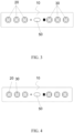
FIG. 2 is a top view schematic view of a top cover assembly provided by a second embodiment of the present disclosure. -
FIG. 3 is a top view schematic view of a top cover assembly provided by a third embodiment of the present disclosure. -
FIG. 4 is a top view schematic view of the top cover assembly provided by the fourth embodiment of the present disclosure. -
FIG. 5 is a structural schematic diagram of a connecting component according to one embodiment of the present disclosure. -
FIG. 6 is a structural schematic diagram of a connecting component according to another embodiment of the present disclosure. -
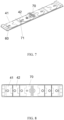
FIG. 7 is a schematic diagram of the structure of the top cover assembly according to the second embodiment of the present disclosure. -
FIG. 8 is a schematic diagram of the structure of the top cover assembly according to the fourth embodiment of the present disclosure. -
FIG. 9 is a schematic diagram of an electrode assembly according to one embodiment of the present disclosure. -
FIG. 10 is a schematic diagram of an electrode assembly according to another embodiment of the present disclosure. -
- 10: top cover;
- 20: first pole;
- 30: second pole;
- 40: connecting component; 41. a first connecting piece; 42. a second connecting piece;
- 50: explosion-proof valve;
- 60: aluminum sheet;
- 70: lower plastic plate; 71. Insulation baffle;
- 80: electrode assembly;
- 91: a first tab; 92: second tab; X: first direction; Y: second direction.
- In the description of the present application, unless otherwise specified and limited, the term "connected to each other", "connected" or "fixed" is to be construed in a broad sense, for example, as fixedly connected, detachably connected, or integrated; mechanically connected or electrically connected; directly connected to each other or indirectly connected to each other via an intermediary; or internally connected between two elements or interactional between two elements. Meanings of the preceding terms in the present application may be understood according to situations.
- In the present application, unless otherwise specified and limited, when a first feature is described as "on" or "below" a second feature, the first feature and the second feature may be in direct contact or be in contact via another feature between the two features instead of being in direct contact. Moreover, when the first feature is described as "on", "above" or "over" the second feature, the first feature is right on, above or over the second feature or the first feature is obliquely on, above or over the second feature, or the first feature is simply at a higher level than the second feature. When the first feature is described as "under", "below" or "underneath" the second feature, the first feature is right under, below or underneath the second feature or the first feature is obliquely under, below or underneath the second feature, or the first feature is simply at a lower level than the second feature.
- In the description of this embodiment, the terms "up", "down", "right", and other azimuth or positional relationships are based on the azimuth or positional relationships shown in the accompanying drawings, only for the convenience of description and simplification of operation, and not to indicate or imply that the referred device or element must have a specific azimuth, be constructed and operated in a specific azimuth, and therefore cannot be understood as a limitation to this application. In addition, the terms "first" and "second" are used only to distinguish in description and have no special meaning.
- As shown in
FIG. 1 to FIG. 4 ,FIG. 7 and FIG. 8 , in a first aspect, embodiments of the present disclosure provide a top cover assembly, the top cover assembly includes atop cover 10, a plurality offirst poles 20 and a plurality ofsecond poles 30. Wherein, the plurality of thefirst poles 20 are arranged on thetop cover 10 at intervals, the plurality of thesecond poles 30 are arranged on thetop cover 10 at intervals, at least one of the plurality of thefirst pole 20 and at least one of the plurality of thesecond pole 30 are arranged adjacent in the first direction X, the plurality of thefirst poles 20 are arranged on thetop cover 10 at intervals in the first direction and the plurality of thesecond poles 30 are arranged on thetop cover 10 at intervals in the first direction X, the plurality of thefirst poles 20 and the plurality of thesecond poles 30 are arranged on thetop cover 10 at the same end of thetop cover 10, or the plurality of thefirst poles 20 are arranged near one end of thetop cover 10, and the plurality of thesecond poles 30 are arranged near the other end of thetop cover 10. - Applying the technical proposal of the present disclosure, the plurality of the
first poles 20 and the plurality of thesecond poles 30 are arranged on thetop cover 10, and the plurality of thefirst poles 20 are arranged on thetop cover 10 at intervals, and the plurality of thesecond poles 30 are also arranged on thetop cover 10 at intervals. Such arrangement can not only meet the output requirements of the top cover assembly, but also can improve the overcurrent ability of the cells, ensure the temperature stability when the cells are used, so as to improve the safety performance of the cells. At least one of the plurality of thefirst pole 20 and at least one of the plurality of thesecond pole 30 are arranged adjacent in the first direction, or a plurality offirst poles 20 are arranged near one end of thetop cover 10, and a plurality ofsecond poles 30 are arranged near the other end of thetop cover 10, so that the diversity of the top cover assembly can be improved to meet the use requirements in different environments, thereby improving the applicability and application range of the device. - In the present disclosure, when the at least one of the plurality of the
first pole 20 and the at least one of the plurality of thesecond pole 30 are disposed adjacent in the first direction, remainingfirst poles 20 and remainingsecond poles 30 may be disposed in parallel in the second direction Y. - Further, the plurality of the
first poles 20 and the plurality of thesecond poles 30 are arranged at intervals along a same straight line. This arrangement can not only make the top cover assembly more beautiful and tidy as a whole, but also facilitate the connection with the external assembly. Alternatively, the plurality of thefirst poles 20 and the plurality of thesecond poles 30 may also be arranged at intervals in other directions, as long as the usage requirements of the device can be met. In the present disclosure, the spacing arrangement specifically means that the plurality of thefirst poles 20 and the plurality of thesecond poles 30 are located on the same straight line. The poles of the two adjacent poles are not limited here, and the specific setting conditions should be selected according to the use environment of the device. - Specifically, the plurality of the
first poles 20 and the plurality of thesecond poles 30 are sequentially alternately arranged in the first direction X. This arrangement makes thefirst pole 20 and thesecond pole 30 uniformly distributed on thetop cover 10, so that the current density during charging and discharging of the cells can be more uniform, so that the heat generation of the cells can be reduced, and the stable operation of the cells can be maintained. - Further, the number of the
first poles 20 is equal to the number of thesecond poles 30. This arrangement can ensure the stability of the cell when it is outputted, so as to maintain the normal operation of the cell. - Wherein, the
first pole 20 is a positive pole, and thesecond pole 30 is a negative pole. - In the embodiments of the present disclosure, when the number of the
first pole 20 and the number of thesecond pole 30 are both two, the two of thefirst poles 20 and the two ofsecond poles 30 are arranged and combined by one of orders: positive-positive-negative-negative, positive-negative-negative-positive, positive-negative-positive-negative, etc., as long as the use requirements of the device can be met. When the number of thefirst pole 20 and the number of thesecond pole 30 are both 3, the three of thefirst poles 20 and the three ofsecond poles 30 are arranged and combined by one of orders: positive-positive-positive-negative-negative-negative, positive-positive-negative-positive-positive-negative, positive-positive-negative-positive-negative-positive, positive-positive-negative-negative-positive-positive, positive-negative-positive-positive-negative-positive, etc., so that the applicability and scope of application of the cell can be improved as much as possible. - At the same time, a distance between any two of the plurality of the
first poles 20 and a distance between the plurality of thesecond poles 30 can also be set to a same distance. Through this uniform distribution design, the current density distribution of the pole pieces is more uniform during the cells are charged and discharged, and the plurality of the poles can evenly share the current to improve the stable operation of the cell. - Of course, in other embodiments of the present disclosure, the number of the
first pole 20 and the number of thesecond pole 30 may not be limited, and the specific arrangement conditions should be selected according to the use requirements of the device, so that the use requirements in different environments can be met. - As shown in
FIG. 5 and FIG 6 , the top cover assembly also includes a plurality of connectingcomponents 40 disposed on one side of thetop cover 10 away from the plurality of thefirst poles 20, and the connectingcomponents 40 are respectively connected to the plurality of thefirst poles 20 or the plurality of thesecond poles 30. In this manner, thefirst pole 20 and thesecond pole 30 can be connected to anelectrode assembly 80 through the connectingmember 40, so as to conduct the internal conduction of the cell. When the polarities of the two adjacent poles are the same, they can be connected in parallel through the connecting components in the figure, so as to facilitate the connection of the multi-pole columns of the cell. - As shown in
FIG. 7 and FIG. 8 , the connectingcomponent 40 includes a first connectingcomponent 41 for paralleling the plurality of thefirst poles 20 and a second connectingcomponent 42 for paralleling the plurality of thesecond poles 30, the first connectingcomponent 41 and the second connectingcomponent 42 are insulated from each other. When the poles of the two adjacent poles are different, it is necessary to use a single connecting piece to connect with the poles, which can ensure the safety during the poles are connected to each other, so as to prevent a short circuit inside the cell, thereby prolonging a service life of the cell. - In the present disclosure, an
insulation baffle 71 is set between the first connectingsheets 41 and the second connectingsheet 42 which are adjacent to each other, so that a risk of short circuit of the cell during use can be avoided, and the stability of the cell during operation can be further maintained. - The connecting
component 40 has a protrusion, and a bottom of thefirst pole 20 and a bottom of thesecond pole 30 have grooves, and shapes and sizes of the protrusions and the grooves are mutually compatible, so that the connectingcomponent 40 can be fitted with thefirst pole 20 or thesecond pole 30 during installation, which not only reduces the installation difficulty of the connectingcomponent 40 and thefirst pole 20 or thesecond pole 30, but also has a simple structure, and can also reduce the production cost of the top cover assembly, so as to realize the mass production of the device. - Specifically, the top cover assembly further includes an explosion-
proof valve 50 disposed on thetop cover 10 and spaced from thefirst poles 20 and thesecond poles 30. This arrangement is mainly to avoid dangerous events such as explosion or fire when the cell is over charged or over discharged. When an expansion is occurred inside the cell occurs, the explosion-proof valve 50 will be opened to reduce the pressure inside the cell, so that the cell can be prevented from being damaged to other components. This is conducive to improving the safety of the cell when it is used. - Of course, in other embodiments of the present disclosure, the number of explosion-
proof valves 50 may not be limited, for example, the number of explosion-proof valves 50 may be two, three and other numbers, as long as the use requirements of the device can be met. At the same time, a liquid injection hole is defined in thetop cover 10, so that it is convenient for a user to add electrolyte to the interior of the cell to ensure uniform infiltration inside the cell, thereby improving the electrical performance of the cell. - Further, the
top cover 10 includes analuminum sheet 60 and alower plastic plate 70 sequentially arranged from top to bottom, thefirst poles 20 and thesecond poles 30 respectively pierce and connect to thealuminum sheet 60 and thelower plastic plate 70, and the connectingcomponent 40 is set on one side of thelower plastic plate 70 away from thealuminum sheet 60. The structure is simple and easy to process, which can not only reduce the processing cost of the device, but also meet the use requirements of the cell during operation. - In the present disclosure, a sealing ring (not shown in the figure) is also provided on the plurality of the
first poles 20 and the plurality of thesecond poles 30. This arrangement can prevent the electrolyte from seeping out from the plurality of thefirst poles 20 and the plurality of thesecond poles 30, thereby causing the phenomenon of liquid leakage, so as to ensure the stability of the cell during operation, so as to further prolong the service life of the cell. - In a second aspect, the embodiments of the present disclosure provide a cell. The cell includes the top cover assembly above-mentioned and an
electrode assembly 80, theelectrode assembly 80 has a plurality of tabs arranged at intervals in the first direction X. The top cover assembly is provided on theelectrode assembly 80 and is connected to the tabs through a connecting piece. In the present disclosure, the number of theelectrode assemblies 80 is two, theelectrode assemblies 80 are arranged sequentially in the second direction Y, so that the current output capability of the cell can be improved to meet the use demand of the user. - As shown in
FIG. 9 and FIG. 10 , the tabs include a plurality offirst tabs 91 and a plurality ofsecond tabs 92, the plurality of thefirst tabs 91 are set in correspondence with the plurality of thefirst poles 20 and the plurality of thesecond tabs 92 are set in correspondence with the plurality of thesecond poles 30. In the present disclosure, a number and an arrangement of the plurality of thefirst tabs 91 and the plurality of thesecond tabs 92 correspond to the plurality of thefirst poles 20 and the plurality of thesecond poles 30, the unity and integrity of the cell structure can be ensured. - In the present disclosure, a length of the cell extending in the first direction X is L, a length of the cell extending in the second direction Y is H, a length of the connecting
component 40 extending in the first direction X is L1, a length of the connectingcomponent 40 extending in the second direction is H1, and a length of the tab extending in the second direction Y is L2, wherein 1/4 L > L1 > 1/9 L, H ≥ H1 > 1/3 H, and 1/2 L > L2 > 1/8 L. - According to the technical proposal of the present disclosure, the plurality of the
first poles 20 and the plurality of thesecond poles 30 are arranged on thetop cover 10, and the plurality of thefirst poles 20 are arranged on thetop cover 10 at intervals, and the plurality of thesecond poles 30 are also arranged on thetop cover 10 at intervals. Such arrangement can not only meet the output requirements of the top cover assembly, but also can improve the overcurrent ability of the cells, ensure the temperature stability when the cells are used, so as to improve the safety performance of the cells. At least one of the plurality of thefirst poles 20 and at least one of the plurality of thesecond poles 30 are arranged adjacent in the first direction, or the plurality of thefirst poles 20 are arranged near one end of thetop cover 10, and the plurality of thesecond poles 30 are arranged near the other end of thetop cover 10, so that the diversity of the top cover assembly can be improved to meet the use requirements in different environments, thereby improving the applicability and application range of the device.
Claims (15)
- A top cover assembly, wherein the top cover assembly comprising:a top cover (10);a plurality of first poles (20) arranged on the top cover (10) at intervals;a plurality of second poles (30) arranged on the top cover (10) at intervals; at least one of the plurality of the first poles (20) and at least one of the plurality of the second poles (30) are arranged adjacent along a first direction;the plurality of the first poles (20) arranged on the top cover (10) at intervals in the first direction, the plurality of the second poles (30) arranged on the top cover (10) at intervals in the first direction, the plurality of the first poles (20) and the plurality of the second poles (30) are arranged at a same end of the top cover (10), or the plurality of the first poles (20) are arranged near one end of the top cover (10), and the plurality of the second poles (30) are arranged near the other end of the top cover (10).
- The top cover assembly according to claim 1, wherein the plurality of the first poles (20) and the plurality of the second poles (30) are sequentially alternately arranged in the first direction.
- The top cover assembly according to claim 1, wherein a number of the first poles (20) is equal to a number of the second poles (30).
- The top cover assembly according to any one of claim 1 to claim 3, wherein the top cover assembly further comprises an explosion-proof valve (50) disposed on the top cover (10) and spaced from the first poles (20) and the second poles (30).
- The top cover assembly according to claim 1, wherein the top cover assembly also comprises a plurality of connecting components (40) disposed on one side of the top cover (10) away from the plurality of the first poles (20), and the connecting components (40) are respectively connected to the plurality of the first pole (20) or the plurality of the second pole (30).
- The top cover assembly according to claim 5, wherein the connecting component (40) comprises a first connecting component (41) for paralleling the plurality of the first poles (20) and a second connecting component (42) for paralleling the plurality of the second poles (30), the first connecting component (41) and the second connecting component (42) are insulated from each other.
- The top cover assembly according to claim 5, wherein the top cover (10) includes an aluminum sheet (60) and a lower plastic plate (70) sequentially arranged from top to bottom, the first poles (20) and the second poles (30) respectively pierce and connect to the aluminum sheet (60) and the lower plastic plate (70), and the connecting component (40) is set on one side of the lower plastic plate (70) away from the aluminum sheet (60).
- A cell, wherein the cell comprises:the top cover assembly according to any one of claim 1 to claim 4 and claim 6 to claim 7;electrode assemblies (80), wherein the electrode assemblies (80) have a plurality of tabs arranged at intervals in the first direction, the top cover assembly is provided over the electrode assemblies (80) and is connected to the tabs through the connecting component of the top cover assembly.
- The cell according to claim 8, wherein the tabs include first tabs (91) and second tabs (92), the first tabs (91) are set in correspondence with the first poles (20) and the second tabs (92) are set in correspondence with the second poles (30).
- The top cover assembly according to claim 1, wherein when at least one of the plurality of the first poles (20) and at least one of the plurality of the second poles (30) are disposed adjacent in the first direction, remaining first poles (20) and remaining second poles (30) are disposed in parallel in the second direction.
- The top cover assembly according to claim 5, wherein the connecting component (40) has a protrusion, and a bottom of the first pole (20) and a bottom of the second pole (30) have grooves, and the protrusions and the grooves are mutually compatible.
- The top cover assembly according to claim 6, wherein an insulation baffle (71) is set between the first connecting sheets (41) and the second connecting sheet (42) which are adjacent to each other.
- The cell according to claim 8, wherein a length of the cell extending in the first direction is L, a length of the connecting component (40) extending in the first direction is L1, wherein 1/4 L>L1 > 1/9L.
- The cell according to claim 13, wherein a length of the cell extending in the second direction is H, a length of the connecting component 40 extending in the second direction is H1, wherein H ≥ H1 > 1/3 H.
- The cell according to claim 13, wherein a length of the tab extending in the second direction is L2, wherein 1/2 L > L2 > 1/8 L.
Priority Applications (1)
| Application Number | Priority Date | Filing Date | Title |
|---|---|---|---|
| MA71709A MA71709A (en) | 2023-12-06 | 2024-09-20 | TOP COVER AND CELL ASSEMBLY |
Applications Claiming Priority (3)
| Application Number | Priority Date | Filing Date | Title |
|---|---|---|---|
| CN202311679845.3A CN117650344A (en) | 2023-12-06 | 2023-12-06 | Top cap subassembly and electric core |
| CN202323334052.6U CN221727382U (en) | 2023-12-06 | 2023-12-06 | Top cover assembly and battery cell |
| PCT/CN2024/082968 WO2025118437A1 (en) | 2023-12-06 | 2024-03-21 | Top cover assembly and battery cell |
Publications (1)
| Publication Number | Publication Date |
|---|---|
| EP4567976A1 true EP4567976A1 (en) | 2025-06-11 |
Family
ID=92894694
Family Applications (1)
| Application Number | Title | Priority Date | Filing Date |
|---|---|---|---|
| EP24201533.7A Pending EP4567976A1 (en) | 2023-12-06 | 2024-09-20 | Top cover assembly and cell |
Country Status (3)
| Country | Link |
|---|---|
| US (1) | US20250192290A1 (en) |
| EP (1) | EP4567976A1 (en) |
| MA (1) | MA71709A (en) |
Citations (1)
| Publication number | Priority date | Publication date | Assignee | Title |
|---|---|---|---|---|
| JP2023541773A (en) * | 2021-06-02 | 2023-10-04 | 寧徳時代新能源科技股▲分▼有限公司 | Battery cells, batteries, power utilization devices, and devices and methods for manufacturing battery cells |
-
2024
- 2024-09-20 MA MA71709A patent/MA71709A/en unknown
- 2024-09-20 EP EP24201533.7A patent/EP4567976A1/en active Pending
- 2024-11-28 US US18/963,599 patent/US20250192290A1/en active Pending
Patent Citations (1)
| Publication number | Priority date | Publication date | Assignee | Title |
|---|---|---|---|---|
| JP2023541773A (en) * | 2021-06-02 | 2023-10-04 | 寧徳時代新能源科技股▲分▼有限公司 | Battery cells, batteries, power utilization devices, and devices and methods for manufacturing battery cells |
Also Published As
| Publication number | Publication date |
|---|---|
| MA71709A (en) | 2025-05-30 |
| US20250192290A1 (en) | 2025-06-12 |
Similar Documents
| Publication | Publication Date | Title |
|---|---|---|
| US20060234125A1 (en) | Lithium Ion Rocking Chair Rechargeable Battery | |
| KR102210218B1 (en) | Battery system, base plate for a battery system and electric vehicle | |
| WO2012050343A2 (en) | Cap assembly having novel structure and cylindrical battery containing same | |
| KR102748475B1 (en) | Battery cell, battery, electrical device, and device and method for manufacturing battery cell | |
| US20250105455A1 (en) | Electrode assembly, battery cell, battery, and electric device | |
| CN101847748A (en) | Lithium-ion power battery | |
| EP4579879A1 (en) | Battery and electrical device | |
| US20250015456A1 (en) | Energy storage apparatus | |
| US20240421450A1 (en) | Battery cell, battery and electricity-consuming device | |
| EP4354532A1 (en) | Electrode assembly, battery cell, battery, and electric apparatus | |
| WO2023160034A1 (en) | Battery box body upper cover, battery box body, battery, and electrical device | |
| CN219144407U (en) | Conductive connecting piece, upper cover assembly and battery pack | |
| US12482893B2 (en) | Battery, electric apparatus, method for preparing battery, and apparatus for preparing battery | |
| EP4567976A1 (en) | Top cover assembly and cell | |
| US20250174779A1 (en) | Battery cell, battery and electricity-consuming device | |
| EP4354574A1 (en) | Battery, electrical device, and method and device for preparing battery | |
| EP4641820A1 (en) | Sampling structure, battery and vehicle | |
| KR100303541B1 (en) | Lithium ion secondary battery | |
| CN117650344A (en) | Top cap subassembly and electric core | |
| CN220604884U (en) | Lithium battery box with double-layer structure | |
| CN220341278U (en) | Battery and electric equipment | |
| US20220407161A1 (en) | Battery, electrical apparatus, and preparation method of battery | |
| CN206931670U (en) | A kind of rechargeable lithium batteries component | |
| CN223651499U (en) | Battery cells and battery packs | |
| CN223858368U (en) | Battery monomer, battery device, energy storage system and charging network |
Legal Events
| Date | Code | Title | Description |
|---|---|---|---|
| PUAI | Public reference made under article 153(3) epc to a published international application that has entered the european phase |
Free format text: ORIGINAL CODE: 0009012 |
|
| STAA | Information on the status of an ep patent application or granted ep patent |
Free format text: STATUS: REQUEST FOR EXAMINATION WAS MADE |
|
| 17P | Request for examination filed |
Effective date: 20240920 |
|
| AK | Designated contracting states |
Kind code of ref document: A1 Designated state(s): AL AT BE BG CH CY CZ DE DK EE ES FI FR GB GR HR HU IE IS IT LI LT LU LV MC ME MK MT NL NO PL PT RO RS SE SI SK SM TR |