EP4567964A1 - Cooling system for battery, battery pack, and vehicle - Google Patents
Cooling system for battery, battery pack, and vehicle Download PDFInfo
- Publication number
- EP4567964A1 EP4567964A1 EP23849446.2A EP23849446A EP4567964A1 EP 4567964 A1 EP4567964 A1 EP 4567964A1 EP 23849446 A EP23849446 A EP 23849446A EP 4567964 A1 EP4567964 A1 EP 4567964A1
- Authority
- EP
- European Patent Office
- Prior art keywords
- cooling plate
- battery
- cooling
- connecting sheet
- battery pack
- Prior art date
- Legal status (The legal status is an assumption and is not a legal conclusion. Google has not performed a legal analysis and makes no representation as to the accuracy of the status listed.)
- Pending
Links
Images


Classifications
-
- B—PERFORMING OPERATIONS; TRANSPORTING
- B60—VEHICLES IN GENERAL
- B60L—PROPULSION OF ELECTRICALLY-PROPELLED VEHICLES; SUPPLYING ELECTRIC POWER FOR AUXILIARY EQUIPMENT OF ELECTRICALLY-PROPELLED VEHICLES; ELECTRODYNAMIC BRAKE SYSTEMS FOR VEHICLES IN GENERAL; MAGNETIC SUSPENSION OR LEVITATION FOR VEHICLES; MONITORING OPERATING VARIABLES OF ELECTRICALLY-PROPELLED VEHICLES; ELECTRIC SAFETY DEVICES FOR ELECTRICALLY-PROPELLED VEHICLES
- B60L58/00—Methods or circuit arrangements for monitoring or controlling batteries or fuel cells, specially adapted for electric vehicles
- B60L58/10—Methods or circuit arrangements for monitoring or controlling batteries or fuel cells, specially adapted for electric vehicles for monitoring or controlling batteries
- B60L58/24—Methods or circuit arrangements for monitoring or controlling batteries or fuel cells, specially adapted for electric vehicles for monitoring or controlling batteries for controlling the temperature of batteries
- B60L58/26—Methods or circuit arrangements for monitoring or controlling batteries or fuel cells, specially adapted for electric vehicles for monitoring or controlling batteries for controlling the temperature of batteries by cooling
-
- H—ELECTRICITY
- H01—ELECTRIC ELEMENTS
- H01M—PROCESSES OR MEANS, e.g. BATTERIES, FOR THE DIRECT CONVERSION OF CHEMICAL ENERGY INTO ELECTRICAL ENERGY
- H01M10/00—Secondary cells; Manufacture thereof
- H01M10/60—Heating or cooling; Temperature control
- H01M10/61—Types of temperature control
- H01M10/613—Cooling or keeping cold
-
- H—ELECTRICITY
- H01—ELECTRIC ELEMENTS
- H01M—PROCESSES OR MEANS, e.g. BATTERIES, FOR THE DIRECT CONVERSION OF CHEMICAL ENERGY INTO ELECTRICAL ENERGY
- H01M10/00—Secondary cells; Manufacture thereof
- H01M10/60—Heating or cooling; Temperature control
- H01M10/62—Heating or cooling; Temperature control specially adapted for specific applications
- H01M10/625—Vehicles
-
- H—ELECTRICITY
- H01—ELECTRIC ELEMENTS
- H01M—PROCESSES OR MEANS, e.g. BATTERIES, FOR THE DIRECT CONVERSION OF CHEMICAL ENERGY INTO ELECTRICAL ENERGY
- H01M10/00—Secondary cells; Manufacture thereof
- H01M10/60—Heating or cooling; Temperature control
- H01M10/64—Heating or cooling; Temperature control characterised by the shape of the cells
- H01M10/647—Prismatic or flat cells, e.g. pouch cells
-
- H—ELECTRICITY
- H01—ELECTRIC ELEMENTS
- H01M—PROCESSES OR MEANS, e.g. BATTERIES, FOR THE DIRECT CONVERSION OF CHEMICAL ENERGY INTO ELECTRICAL ENERGY
- H01M10/00—Secondary cells; Manufacture thereof
- H01M10/60—Heating or cooling; Temperature control
- H01M10/65—Means for temperature control structurally associated with the cells
- H01M10/655—Solid structures for heat exchange or heat conduction
- H01M10/6551—Surfaces specially adapted for heat dissipation or radiation, e.g. fins or coatings
-
- H—ELECTRICITY
- H01—ELECTRIC ELEMENTS
- H01M—PROCESSES OR MEANS, e.g. BATTERIES, FOR THE DIRECT CONVERSION OF CHEMICAL ENERGY INTO ELECTRICAL ENERGY
- H01M10/00—Secondary cells; Manufacture thereof
- H01M10/60—Heating or cooling; Temperature control
- H01M10/65—Means for temperature control structurally associated with the cells
- H01M10/655—Solid structures for heat exchange or heat conduction
- H01M10/6553—Terminals or leads
-
- H—ELECTRICITY
- H01—ELECTRIC ELEMENTS
- H01M—PROCESSES OR MEANS, e.g. BATTERIES, FOR THE DIRECT CONVERSION OF CHEMICAL ENERGY INTO ELECTRICAL ENERGY
- H01M10/00—Secondary cells; Manufacture thereof
- H01M10/60—Heating or cooling; Temperature control
- H01M10/65—Means for temperature control structurally associated with the cells
- H01M10/655—Solid structures for heat exchange or heat conduction
- H01M10/6554—Rods or plates
-
- H—ELECTRICITY
- H01—ELECTRIC ELEMENTS
- H01M—PROCESSES OR MEANS, e.g. BATTERIES, FOR THE DIRECT CONVERSION OF CHEMICAL ENERGY INTO ELECTRICAL ENERGY
- H01M10/00—Secondary cells; Manufacture thereof
- H01M10/60—Heating or cooling; Temperature control
- H01M10/65—Means for temperature control structurally associated with the cells
- H01M10/655—Solid structures for heat exchange or heat conduction
- H01M10/6556—Solid parts with flow channel passages or pipes for heat exchange
-
- H—ELECTRICITY
- H01—ELECTRIC ELEMENTS
- H01M—PROCESSES OR MEANS, e.g. BATTERIES, FOR THE DIRECT CONVERSION OF CHEMICAL ENERGY INTO ELECTRICAL ENERGY
- H01M10/00—Secondary cells; Manufacture thereof
- H01M10/60—Heating or cooling; Temperature control
- H01M10/65—Means for temperature control structurally associated with the cells
- H01M10/656—Means for temperature control structurally associated with the cells characterised by the type of heat-exchange fluid
- H01M10/6567—Liquids
- H01M10/6568—Liquids characterised by flow circuits, e.g. loops, located externally to the cells or cell casings
-
- H—ELECTRICITY
- H01—ELECTRIC ELEMENTS
- H01M—PROCESSES OR MEANS, e.g. BATTERIES, FOR THE DIRECT CONVERSION OF CHEMICAL ENERGY INTO ELECTRICAL ENERGY
- H01M50/00—Constructional details or processes of manufacture of the non-active parts of electrochemical cells other than fuel cells, e.g. hybrid cells
- H01M50/20—Mountings; Secondary casings or frames; Racks, modules or packs; Suspension devices; Shock absorbers; Transport or carrying devices; Holders
-
- H—ELECTRICITY
- H01—ELECTRIC ELEMENTS
- H01M—PROCESSES OR MEANS, e.g. BATTERIES, FOR THE DIRECT CONVERSION OF CHEMICAL ENERGY INTO ELECTRICAL ENERGY
- H01M50/00—Constructional details or processes of manufacture of the non-active parts of electrochemical cells other than fuel cells, e.g. hybrid cells
- H01M50/20—Mountings; Secondary casings or frames; Racks, modules or packs; Suspension devices; Shock absorbers; Transport or carrying devices; Holders
- H01M50/249—Mountings; Secondary casings or frames; Racks, modules or packs; Suspension devices; Shock absorbers; Transport or carrying devices; Holders specially adapted for aircraft or vehicles, e.g. cars or trains
-
- H—ELECTRICITY
- H01—ELECTRIC ELEMENTS
- H01M—PROCESSES OR MEANS, e.g. BATTERIES, FOR THE DIRECT CONVERSION OF CHEMICAL ENERGY INTO ELECTRICAL ENERGY
- H01M2220/00—Batteries for particular applications
- H01M2220/20—Batteries in motive systems, e.g. vehicle, ship, plane
-
- Y—GENERAL TAGGING OF NEW TECHNOLOGICAL DEVELOPMENTS; GENERAL TAGGING OF CROSS-SECTIONAL TECHNOLOGIES SPANNING OVER SEVERAL SECTIONS OF THE IPC; TECHNICAL SUBJECTS COVERED BY FORMER USPC CROSS-REFERENCE ART COLLECTIONS [XRACs] AND DIGESTS
- Y02—TECHNOLOGIES OR APPLICATIONS FOR MITIGATION OR ADAPTATION AGAINST CLIMATE CHANGE
- Y02E—REDUCTION OF GREENHOUSE GAS [GHG] EMISSIONS, RELATED TO ENERGY GENERATION, TRANSMISSION OR DISTRIBUTION
- Y02E60/00—Enabling technologies; Technologies with a potential or indirect contribution to GHG emissions mitigation
- Y02E60/10—Energy storage using batteries
Definitions
- the present disclosure relates to the field of battery technologies, and specifically, to a cooling system for a battery, a battery pack, and a vehicle.
- a connecting sheet in a battery pack is passively and naturally cooled only by a small amount of air in the battery pack.
- this manner has a limited heat dissipation capability and a poor heat dissipation effect.
- An objective of the present disclosure is to provide a cooling system for a battery, a battery pack, and a vehicle. Therefore, efficient heat dissipation of a connecting sheet can be implemented.
- the present disclosure provides a cooling system for a battery comprising a main cooling plate and a connecting sheet cooling plate.
- a first cooling channel is provided in the main cooling plate.
- the main cooling plate is configured to cool a battery cell.
- the connecting sheet cooling plate is arranged on the main cooling plate.
- a second cooling channel is provided in the connecting sheet cooling plate.
- the connecting sheet cooling plate is configured to cool a connecting sheet.
- the first cooling channel and the second cooling channel are independent of each other and do not communicate with each other.
- the first cooling channel communicates with the second cooling channel.
- first connectors are arranged at an inlet and an outlet of the second cooling channel respectively, a plurality of second connectors are arranged on the main cooling plate, and the second connectors and the first connectors are in a one-to-one correspondence and communicate with each other.
- a sealing hose is sleeved at a joint between the first connector and the second connector.
- the present disclosure further provides a battery pack, comprising the cooling system for a battery.
- the battery pack further comprises a plurality of battery cells and a plurality of connecting sheets, the battery cells are fixedly arranged on the main cooling plate, the connecting sheets are connected to terminals of the battery cells, and the connecting sheet cooling plate is fixedly connected to the connecting sheets.
- the battery cells are fixedly connected to the main cooling plate through a heat conductive adhesive.
- the connecting sheet cooling plate is fixedly connected to the connecting sheet through a heat conductive adhesive.
- the battery pack further comprises a battery tray, the main cooling plate comprises a first cooling plate, and the first cooling plate is integrated on the battery tray.
- the battery tray comprises an outer frame and a bottom plate, and the first cooling plate is integrated on the bottom plate.
- the battery pack further comprises a sealing cover
- the main cooling plate further comprises a second cooling plate
- the second cooling plate is integrated on the sealing cover.
- the present disclosure further provides a vehicle, comprising the cooling system for a battery or the battery pack.
- the first cooling channel is provided in the main cooling plate.
- a cooling medium for example, a coolant
- the second cooling channel is provided in the connecting sheet cooling plate.
- a cooling medium for example, a coolant
- a connecting sheet In a battery pack of an electric vehicle, a connecting sheet is generally arranged.
- the connecting sheet is firmly connected to a terminal of a battery cell (Cell) in a welding manner or another connection manner, to implement series and parallel connection between battery cells.
- Cell battery cell
- a battery, the connecting sheet, and another electrical connection structure are all subjected to a continuous large current. Resistance of the connecting sheet and the other electrical connection structure and resistance increased by welding all generate a large amount of heat. If the heat generated by the connecting sheet and the other electrical connection structure cannot be dissipated in time, a temperature of the battery increases. Consequently, performance, a service life, and the like of the battery are affected.
- a cooling system 100 for a battery comprising a main cooling plate 1 and a connecting sheet cooling plate 2.
- a first cooling channel is provided in the main cooling plate 1.
- the main cooling plate 1 is configured to cool a battery cell 4.
- the connecting sheet cooling plate 2 is arranged on the main cooling plate 1.
- a second cooling channel is provided in the connecting sheet cooling plate 2.
- the connecting sheet cooling plate 2 is configured to cool a connecting sheet 5.
- the cooling system 100 for a battery provided in the present disclosure comprises the main cooling plate 1 and the connecting sheet cooling plate 2.
- the first cooling channel is provided in the main cooling plate 1.
- a cooling medium for example, a coolant
- the second cooling channel is provided in the connecting sheet cooling plate 2.
- a cooling medium for example, a coolant
- a cooling medium is introduced into the second cooling channel in the connecting sheet cooling plate 2, to implement heat dissipation and cooling of the connecting sheet 5.
- efficient and timely heat dissipation can be performed on the connecting sheet 5 in the battery pack through the added connecting sheet cooling plate 2, so that an impact on performance and a service life of the battery caused by overheating of the connecting sheet 5 is reduced.
- the main cooling plate 1 may be a complete liquid cooling plate, or may be spliced by a plurality of liquid cooling plates.
- the main cooling plate 1 comprises an inlet connector 11 and an outlet connector 12. Both the inlet connector 11 and the outlet connector 12 communicate with the first cooling channel.
- the connecting sheet cooling plate 2 is arranged above the main cooling plate 1.
- the connecting sheet cooling plate 2 may be a metal extruded harmonica tube, a serpentine tube, or a stamped brazing plate.
- a specific position of the connecting sheet cooling plate 2 on the main cooling plate 1 may be determined based on a position of the connecting sheet 5. This is not specifically limited in the present disclosure.
- the connecting sheet cooling plate 2 may be arranged on each liquid cooling plate. Alternatively, a same connecting sheet cooling plate 2 may be arranged across at least two liquid cooling plates. This is not specifically limited in the present disclosure.
- the first cooling channel and the second cooling channel may be independent of each other and do not communicate with each other, to implement independent control of the main cooling plate 1 and the connecting sheet cooling plate 2.
- a substance introduced into the second cooling channel may be a coolant.
- the first cooling channel and the second cooling channel may alternatively communicate with each other, so that channels configured for a cooling medium (for example, a coolant) to flow in the entire cooling system 100 for a battery forms a path.
- a cooling medium for example, a coolant
- the coolant can flow in the first cooling channel of the main cooling plate 1 and the second cooling channel of the connecting sheet cooling plate 2, and there is no need to connect each connecting sheet cooling plate 2 to a coolant transfer device.
- the main cooling plate 1 and the connecting sheet cooling plate 2 share a same coolant transfer device. In this way, arrangement of a plurality of coolant transfer devices can be avoided, so that internal space of the battery pack is saved, and costs of the battery pack can also be reduced.
- first connectors 21 may be arranged at an inlet of the second cooling channel and an outlet of the second cooling channel respectively, a plurality of second connectors 13 are arranged on the main cooling plate 1, and the second connectors 13 and the first connectors 21 are in a one-to-one correspondence and communicate with each other.
- both the first connectors 21 and the second connectors 13 are extended connector structures, and the second connectors 13 and the first connectors 21 are arranged in a one-to-one correspondence manner, to facilitate the communication between the first cooling channel and the second cooling channel.
- the connecting sheet cooling plate 2 has a length. Two first connectors 21 are arranged at two ends of the connecting sheet cooling plate 2 respectively along a length direction. Both the first connectors 21 and the second connectors 13 may be metal connectors, and each first connector 21 and a corresponding second connector 13 extend toward each other.
- a sealing hose 3 is sleeved at the joint of the first connector 21 and the second connector 13.
- the sealing hose 3 is configured to seal the joint of the first connector 21 and the second connector 13, so that the coolant does not easily flow out from the cooling system 100 for a battery, and a possibility that the coolant affects another structure such as the battery cell 4 in the battery pack is also reduced.
- An inner wall of the sealing hose 3 is arranged close to peripheral walls of the first connector 21 and the second connector 13.
- the present disclosure further provides a battery pack 200.
- the battery pack 200 comprises the foregoing cooling system 100 for a battery.
- the connecting sheet cooling plate 2 that performs cooling and heat dissipation on the connecting sheet 5 is arranged in the battery pack 200, to avoid affecting use of the battery pack 200 due to overheating of the connecting sheet 5.
- the battery pack 200 provided in the present disclosure also has the foregoing features. To avoid repetition, details are not described herein again.
- the battery pack 200 further comprises a plurality of battery cells 4 and a plurality of connecting sheets 5, the battery cells 4 are fixedly arranged on the main cooling plate 1, the connecting sheets 5 are connected to terminals of the battery cells 4, and the connecting sheet cooling plate 2 is fixedly connected to the connecting sheets 5.
- the battery cells 4 are arranged on the main cooling plate 1, which facilitates heat dissipation and cooling of the battery cell 4.
- the connecting sheet cooling plate 2 and the connecting sheet 5 are fixedly arranged, so that the connecting sheet cooling plate 2 can better perform heat dissipation and cooling on a heating connecting sheet 5.
- the plurality of battery cells 4 are arranged along a first direction, and form a battery cell column (comprising a column of the battery cells 4 and another structure connected or arranged on the battery cell 4) through a fixed support 41.
- An aerogel 42 is arranged between adjacent battery cells 4.
- the aerogel 42 implements heat insulation between the battery cells 4, and can absorb expansion of the battery cell 4.
- the fixed support 41 extends along the first direction.
- a plurality of connecting sheets 5 arranged at intervals along the first direction are arranged on two opposite sides of each battery cell column respectively, and the connecting sheets 5 are configured to communicate with the plurality of battery cells 4 in the battery cell column, to form a battery module.
- one connecting sheet cooling plate 2 may be fixed to an outer side of the connecting sheet 5 located at a same side of the battery cell column, or a plurality of connecting sheet cooling plates 2 arranged along the first direction may be fixed to an outer side of the connecting sheet 5 located at a same side of the battery cell column.
- the battery pack 200 further comprises a flexible circuit board 6 and a protective housing 7.
- the flexible circuit board 6 and the protective housing 7 both extend along the first direction.
- the connecting sheet cooling plate 2 is located between the flexible circuit board 6 and the connecting sheet 5.
- the flexible circuit board 6 is configured to monitor and measure a voltage and a temperature of the battery module, and communicate with an entire battery management system (battery management system, BMS).
- BMS battery management system
- the protective housing 7 covers outer sides of the flexible circuit board 6, the connecting sheet cooling plate 2, and the connecting sheet 5. The protective housing 7 is engaged with the fixed support 41, to protect the foregoing structure.
- the battery cell 4 may be fixedly connected to the main cooling plate 1 through the heat conductive adhesive.
- the heat conductive adhesive between the battery cell 4 and the main cooling plate 1 may be a first heat conductive adhesive 43.
- the connecting sheet cooling plate 2 may also be fixedly connected to the connecting sheet 5 through the heat conductive adhesive.
- the heat conductive adhesive between the connecting sheet 5 and the connecting sheet cooling plate 2 may be a second heat conductive adhesive 51.
- the battery pack 200 further comprises a battery tray 201
- the main cooling plate 1 may comprise a first cooling plate 14
- the first cooling plate 14 may be integrated on the battery tray 201.
- the battery module is placed on the battery tray 201, and heat dissipation is directly performed through the first cooling plate 14 integrated on the battery tray 201, so that an integration degree of the first cooling plate 14 and the battery pack 200 after being combined is higher, and heat dissipation is easily performed on the battery cell 4 in the battery module.
- first cooling plate 14 and the battery tray 201 may alternatively be two independent structures fixed together, and the first cooling plate 14 and the battery tray 201 may alternatively be integrated into a same structure (that is, the battery tray 201 with a liquid cooling function is formed).
- the battery tray 201 comprises a bottom plate 9 and an outer frame 8.
- the outer frame 8 is a frame structure formed by welding an extruded material.
- the outer frame 8 is enclosed outside the battery module.
- the first cooling plate 14 is integrated on the bottom plate 9, and the bottom plate 9 and the first cooling plate 14 integrated together are fixed to the bottom of the outer frame 8 by friction stir welding or in another form.
- the battery module is fixed to the first cooling plate 14 integrated with the bottom plate through a heat conductive adhesive or the heat conductive structural adhesive.
- One or more battery modules may be arranged in the outer frame 8. This is not specifically limited in the present disclosure.
- FIG. 7 In the embodiment shown in FIG. 7 , four battery modules are arranged in the outer frame 8.
- An intermediate expansion beam 81 and an intermediate longitudinal beam 82 are fixed to an inner wall of the outer frame 8, and the intermediate expansion beam 81 and the intermediate longitudinal beam 82 are cross-connected in the outer frame 8 in a "cross" shape, so that an interior of the outer frame 8 is divided into four regions, and one battery module may be arranged in each region.
- only one connecting sheet cooling plate 2 may be arranged on the connecting sheet 5 located at a same side of the two battery modules, a height of the intermediate expansion beam 81 can avoid the connecting sheet cooling plate 2, and the first cooling plate 14 is bonded to lower surfaces of the battery cells 4 of all battery modules in the outer frame 8 through the heat conductive adhesive or the heat conductive structural adhesive.
- the battery pack 200 further comprises a sealing cover
- the main cooling plate 1 further comprises a second cooling plate 15
- the second cooling plate 15 may be integrated on the sealing cover.
- the sealing cover can also have an effect of cooling the battery cell, to efficient perform cool and heat dissipation on the battery cell.
- the second cooling plate 15 and the sealing cover may be two independent structures fixed together, and the second cooling plate 15 and the sealing cover may alternatively be integrated into a same structure (that is, a sealing cover having a cooling function is formed), so that the battery pack 200 of the present disclosure has a higher degree of integration.
- the second cooling plate 15 integrated with the sealing cover may be fixedly connected to upper surfaces of the battery cells 4 of all the battery modules in the outer frame 8 through the heat conductive adhesive or the heat conductive structural adhesive.
- the connecting sheet cooling plate 2 may communicate with the first cooling plate 14, or may communicate with the second cooling plate 15, or may communicate with both the first cooling plate 14 and the second cooling plate 15. This is not specifically limited in the present disclosure.
- the main cooling plate 1 may comprise only the first cooling plate 14, and a sealing plate may be a cover plate made of plastic or metal, and is arranged on the battery tray 201.
- the present disclosure further provides a vehicle 300.
- the vehicle 300 comprises the foregoing cooling system 100 for a battery or the foregoing battery pack 200.
- the vehicle 300 in which the cooling system 100 for a battery or the battery pack 200 of the present disclosure is arranged is not affected by overheating of the connecting sheet 5, so that performance of the vehicle 300 is more stable during operation, and a failure rate of the vehicle 300 is reduced.
- the battery pack 200 may be mounted on the vehicle 300, or may be arranged in a form of integrated battery vehicle body.
- the main cooling plate 1 is fixedly arranged on the battery cell 4.
- the connecting sheet cooling plate 2 is fixedly arranged on the outer side of the connecting sheet 5, and the coolant or a refrigerant is introduced into the main cooling plate 1 and the connecting sheet cooling plate 2.
- heat dissipation is performed on the battery cell 4, heat dissipation is also performed on the connecting sheet 5, so that the connecting sheet 5 is no longer passively cooled only by air.
- the connecting sheet cooling plate 2 is arranged to directly actively cool the connecting sheet 5, to implement efficient cooling of the connecting sheet 5 and reduce impact of overheating of the connecting sheet 5 on performance and a service life of the battery.
Landscapes
- Engineering & Computer Science (AREA)
- Chemical & Material Sciences (AREA)
- Chemical Kinetics & Catalysis (AREA)
- Electrochemistry (AREA)
- General Chemical & Material Sciences (AREA)
- Manufacturing & Machinery (AREA)
- Life Sciences & Earth Sciences (AREA)
- Sustainable Development (AREA)
- Sustainable Energy (AREA)
- Power Engineering (AREA)
- Transportation (AREA)
- Mechanical Engineering (AREA)
- Aviation & Aerospace Engineering (AREA)
- Secondary Cells (AREA)
- Battery Mounting, Suspending (AREA)
Abstract
Description
- The present disclosure claims priority to and benefits of
Chinese Patent Application No. 202222024670.X, filed on August 2, 2022 - The present disclosure relates to the field of battery technologies, and specifically, to a cooling system for a battery, a battery pack, and a vehicle.
- In the related art, a connecting sheet in a battery pack is passively and naturally cooled only by a small amount of air in the battery pack. However, this manner has a limited heat dissipation capability and a poor heat dissipation effect.
- An objective of the present disclosure is to provide a cooling system for a battery, a battery pack, and a vehicle. Therefore, efficient heat dissipation of a connecting sheet can be implemented.
- To achieve the foregoing objective, the present disclosure provides a cooling system for a battery comprising a main cooling plate and a connecting sheet cooling plate. A first cooling channel is provided in the main cooling plate. The main cooling plate is configured to cool a battery cell. The connecting sheet cooling plate is arranged on the main cooling plate. A second cooling channel is provided in the connecting sheet cooling plate. The connecting sheet cooling plate is configured to cool a connecting sheet.
- Optionally, the first cooling channel and the second cooling channel are independent of each other and do not communicate with each other.
- Optionally, the first cooling channel communicates with the second cooling channel.
- Optionally, first connectors are arranged at an inlet and an outlet of the second cooling channel respectively, a plurality of second connectors are arranged on the main cooling plate, and the second connectors and the first connectors are in a one-to-one correspondence and communicate with each other.
- Optionally, a sealing hose is sleeved at a joint between the first connector and the second connector.
- Based on the foregoing technical solution, the present disclosure further provides a battery pack, comprising the cooling system for a battery.
- Optionally, the battery pack further comprises a plurality of battery cells and a plurality of connecting sheets, the battery cells are fixedly arranged on the main cooling plate, the connecting sheets are connected to terminals of the battery cells, and the connecting sheet cooling plate is fixedly connected to the connecting sheets.
- Optionally, the battery cells are fixedly connected to the main cooling plate through a heat conductive adhesive.
- Optionally, the connecting sheet cooling plate is fixedly connected to the connecting sheet through a heat conductive adhesive.
- Optionally, the battery pack further comprises a battery tray, the main cooling plate comprises a first cooling plate, and the first cooling plate is integrated on the battery tray.
- Optionally, the battery tray comprises an outer frame and a bottom plate, and the first cooling plate is integrated on the bottom plate.
- Optionally, the battery pack further comprises a sealing cover, the main cooling plate further comprises a second cooling plate, and the second cooling plate is integrated on the sealing cover.
- Based on the foregoing technical solution, the present disclosure further provides a vehicle, comprising the cooling system for a battery or the battery pack.
- Through the foregoing technical solution, the cooling system for a battery provided in the present disclosure comprises the main cooling plate and the connecting sheet cooling plate. The first cooling channel is provided in the main cooling plate. A cooling medium (for example, a coolant) is introduced into the first cooling channel in the main cooling plate, to implement heat dissipation and cooling of the battery cell. In addition, the second cooling channel is provided in the connecting sheet cooling plate. A cooling medium (for example, a coolant) is introduced into the second cooling channel in the connecting sheet cooling plate, to implement heat dissipation and cooling of the connecting sheet. Efficient and timely heat dissipation can be performed on the connecting sheet in the battery pack through the added connecting sheet cooling plate, so that an impact on performance and a service life of the battery caused by overheating of the connecting sheet is reduced.
- Other features and advantages of the present disclosure are described in detail in the following detailed description part.
- The accompanying drawings are provided for further understanding of the present disclosure and constitute a part of the specification, and explain the present disclosure together with the following specific implementations, but do not constitute a limitation to the present disclosure. In the figures:
-
FIG. 1 is a schematic structural diagram of a cooling system for a battery according to an exemplary embodiment of the present disclosure; -
FIG. 2 is an enlarged view of a position A inFIG. 1 ; -
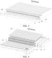
FIG. 3 is a partial schematic structural diagram of a battery pack according to an exemplary embodiment of the present disclosure; -
FIG. 4 is a three-dimensional exploded view of a battery pack according to an exemplary embodiment of the present disclosure; -
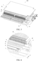
FIG. 5 is another three-dimensional exploded view of a battery pack according to an exemplary embodiment of the present disclosure; -
FIG. 6 is an enlarged view of a position B inFIG. 5 ; -
FIG. 7 is a schematic structural diagram of a battery tray in a battery pack according to an exemplary embodiment of the present disclosure; and -
FIG. 8 is a schematic diagram of a vehicle according to an exemplary embodiment of the present disclosure. - 1-main cooling plate; 11-inlet connector; 12-outlet connector; 13-second connector; 14-first cooling plate; 15-second cooling plate; 2-connecting sheet cooling plate; 21-first connector; 3-sealing hose; 4-battery cell; 41-fixed support; 42-aerogel; 43-first heat conductive adhesive; 5-connecting sheet; 51-second heat conductive adhesive; 6-flexible circuit board; 7-protective housing; 8-outer frame; 81-expansion beam; 82-intermediate longitudinal beam; 9-bottom plate; 100-cooling system for battery; 200-battery pack; 201-battery tray; and 300-vehicle.
- The following describes the specific implementations of the present disclosure in detail with reference to the accompanying drawings. It should be understood that the specific implementations described herein are merely used to describe and explain the present disclosure, but are not intended to limit the present disclosure.
- In the present disclosure, unless otherwise specified, used orientation terms such as "inside and outside" are for the contour of a corresponding component. In addition, when the following descriptions relate to the accompanying drawings, unless indicated otherwise, same numbers in different accompanying drawings represent same or similar elements. The implementations described in the following exemplary embodiments do not represent all implementations consistent with the present disclosure. Instead, they are merely examples of apparatuses and methods consistent with some aspects related to the present disclosure as recited in the appended claims.
- In a battery pack of an electric vehicle, a connecting sheet is generally arranged. The connecting sheet is firmly connected to a terminal of a battery cell (Cell) in a welding manner or another connection manner, to implement series and parallel connection between battery cells. During fast charging, a battery, the connecting sheet, and another electrical connection structure are all subjected to a continuous large current. Resistance of the connecting sheet and the other electrical connection structure and resistance increased by welding all generate a large amount of heat. If the heat generated by the connecting sheet and the other electrical connection structure cannot be dissipated in time, a temperature of the battery increases. Consequently, performance, a service life, and the like of the battery are affected.
- According to the specific implementations of the present disclosure, referring to
FIG. 1 to FIG. 7 , acooling system 100 for a battery is provided, comprising amain cooling plate 1 and a connectingsheet cooling plate 2. A first cooling channel is provided in themain cooling plate 1. Themain cooling plate 1 is configured to cool abattery cell 4. The connectingsheet cooling plate 2 is arranged on themain cooling plate 1. A second cooling channel is provided in the connectingsheet cooling plate 2. The connectingsheet cooling plate 2 is configured to cool a connectingsheet 5. - Through the foregoing technical solution, the
cooling system 100 for a battery provided in the present disclosure comprises themain cooling plate 1 and the connectingsheet cooling plate 2. The first cooling channel is provided in themain cooling plate 1. A cooling medium (for example, a coolant) is introduced into the first cooling channel in themain cooling plate 1, to implement heat dissipation and cooling of thebattery cell 4. In addition, the second cooling channel is provided in the connectingsheet cooling plate 2. In thecooling system 100 for a battery provided in the present disclosure, a cooling medium (for example, a coolant) is introduced into the second cooling channel in the connectingsheet cooling plate 2, to implement heat dissipation and cooling of the connectingsheet 5. In addition, efficient and timely heat dissipation can be performed on the connectingsheet 5 in the battery pack through the added connectingsheet cooling plate 2, so that an impact on performance and a service life of the battery caused by overheating of the connectingsheet 5 is reduced. - Referring to
FIG. 1 , themain cooling plate 1 may be a complete liquid cooling plate, or may be spliced by a plurality of liquid cooling plates. Themain cooling plate 1 comprises aninlet connector 11 and anoutlet connector 12. Both theinlet connector 11 and theoutlet connector 12 communicate with the first cooling channel. When themain cooling plate 1 is a complete liquid cooling plate, the connectingsheet cooling plate 2 is arranged above themain cooling plate 1. The connectingsheet cooling plate 2 may be a metal extruded harmonica tube, a serpentine tube, or a stamped brazing plate. A specific position of the connectingsheet cooling plate 2 on themain cooling plate 1 may be determined based on a position of the connectingsheet 5. This is not specifically limited in the present disclosure. When themain cooling plate 1 is spliced by a plurality of liquid cooling plates, the connectingsheet cooling plate 2 may be arranged on each liquid cooling plate. Alternatively, a same connectingsheet cooling plate 2 may be arranged across at least two liquid cooling plates. This is not specifically limited in the present disclosure. - In an implementation provided in the present disclosure, the first cooling channel and the second cooling channel may be independent of each other and do not communicate with each other, to implement independent control of the
main cooling plate 1 and the connectingsheet cooling plate 2. When themain cooling plate 1 and the connectingsheet cooling plate 2 are independent of each other and do not communicate with each other, a substance introduced into the second cooling channel may be a coolant. - In another implementation provided in the present disclosure, referring to
FIG. 1 , the first cooling channel and the second cooling channel may alternatively communicate with each other, so that channels configured for a cooling medium (for example, a coolant) to flow in theentire cooling system 100 for a battery forms a path. After the coolant is introduced into themain cooling plate 1, the coolant can flow in the first cooling channel of themain cooling plate 1 and the second cooling channel of the connectingsheet cooling plate 2, and there is no need to connect each connectingsheet cooling plate 2 to a coolant transfer device. In other words, themain cooling plate 1 and the connectingsheet cooling plate 2 share a same coolant transfer device. In this way, arrangement of a plurality of coolant transfer devices can be avoided, so that internal space of the battery pack is saved, and costs of the battery pack can also be reduced. - When the first cooling channel communicates with the second cooling channel, referring to
FIG. 1 and FIG. 2 ,first connectors 21 may be arranged at an inlet of the second cooling channel and an outlet of the second cooling channel respectively, a plurality ofsecond connectors 13 are arranged on themain cooling plate 1, and thesecond connectors 13 and thefirst connectors 21 are in a one-to-one correspondence and communicate with each other. In the foregoing design manner, both thefirst connectors 21 and thesecond connectors 13 are extended connector structures, and thesecond connectors 13 and thefirst connectors 21 are arranged in a one-to-one correspondence manner, to facilitate the communication between the first cooling channel and the second cooling channel. The connectingsheet cooling plate 2 has a length. Twofirst connectors 21 are arranged at two ends of the connectingsheet cooling plate 2 respectively along a length direction. Both thefirst connectors 21 and thesecond connectors 13 may be metal connectors, and eachfirst connector 21 and a correspondingsecond connector 13 extend toward each other. - To reduce a possibility of coolant leakage at a joint of the
first connector 21 and thesecond connector 13, in an implementation provided in the present disclosure, referring toFIG. 2 , a sealinghose 3 is sleeved at the joint of thefirst connector 21 and thesecond connector 13. The sealinghose 3 is configured to seal the joint of thefirst connector 21 and thesecond connector 13, so that the coolant does not easily flow out from thecooling system 100 for a battery, and a possibility that the coolant affects another structure such as thebattery cell 4 in the battery pack is also reduced. An inner wall of the sealinghose 3 is arranged close to peripheral walls of thefirst connector 21 and thesecond connector 13. - Based on the foregoing technical solution, the present disclosure further provides a
battery pack 200. Referring toFIG. 3 to FIG. 6 , thebattery pack 200 comprises the foregoingcooling system 100 for a battery. Through this design manner, the connectingsheet cooling plate 2 that performs cooling and heat dissipation on the connectingsheet 5 is arranged in thebattery pack 200, to avoid affecting use of thebattery pack 200 due to overheating of the connectingsheet 5. Thebattery pack 200 provided in the present disclosure also has the foregoing features. To avoid repetition, details are not described herein again. - In an implementation provided in the present disclosure, referring to
FIG. 3 , thebattery pack 200 further comprises a plurality ofbattery cells 4 and a plurality of connectingsheets 5, thebattery cells 4 are fixedly arranged on themain cooling plate 1, the connectingsheets 5 are connected to terminals of thebattery cells 4, and the connectingsheet cooling plate 2 is fixedly connected to the connectingsheets 5. In the foregoing design manner, thebattery cells 4 are arranged on themain cooling plate 1, which facilitates heat dissipation and cooling of thebattery cell 4. Similarly, the connectingsheet cooling plate 2 and the connectingsheet 5 are fixedly arranged, so that the connectingsheet cooling plate 2 can better perform heat dissipation and cooling on aheating connecting sheet 5. - Referring to
FIG. 3 and FIG. 4 , the plurality ofbattery cells 4 are arranged along a first direction, and form a battery cell column (comprising a column of thebattery cells 4 and another structure connected or arranged on the battery cell 4) through a fixedsupport 41. Anaerogel 42 is arranged betweenadjacent battery cells 4. Theaerogel 42 implements heat insulation between thebattery cells 4, and can absorb expansion of thebattery cell 4. The fixedsupport 41 extends along the first direction. A plurality of connectingsheets 5 arranged at intervals along the first direction are arranged on two opposite sides of each battery cell column respectively, and the connectingsheets 5 are configured to communicate with the plurality ofbattery cells 4 in the battery cell column, to form a battery module. It should be noted that, one connectingsheet cooling plate 2 may be fixed to an outer side of the connectingsheet 5 located at a same side of the battery cell column, or a plurality of connectingsheet cooling plates 2 arranged along the first direction may be fixed to an outer side of the connectingsheet 5 located at a same side of the battery cell column. - In an implementation provided in the present disclosure, referring to
FIG. 3 and FIG. 4 , thebattery pack 200 further comprises aflexible circuit board 6 and aprotective housing 7. Theflexible circuit board 6 and theprotective housing 7 both extend along the first direction. The connectingsheet cooling plate 2 is located between theflexible circuit board 6 and the connectingsheet 5. Theflexible circuit board 6 is configured to monitor and measure a voltage and a temperature of the battery module, and communicate with an entire battery management system (battery management system, BMS). Theprotective housing 7 covers outer sides of theflexible circuit board 6, the connectingsheet cooling plate 2, and the connectingsheet 5. Theprotective housing 7 is engaged with the fixedsupport 41, to protect the foregoing structure. - Referring to
FIG. 3 to FIG. 5 , to ensure that thebattery cell 4 is firmly connected to themain cooling plate 1 without affecting heat conduction, in an implementation provided in the present disclosure, thebattery cell 4 may be fixedly connected to themain cooling plate 1 through the heat conductive adhesive. The heat conductive adhesive between thebattery cell 4 and themain cooling plate 1 may be a firstheat conductive adhesive 43. In addition, to ensure that the connectingsheet 5 is firmly connected to the connectingsheet cooling plate 2 without affecting the heat conduction, in an implementation provided in the present disclosure, the connectingsheet cooling plate 2 may also be fixedly connected to the connectingsheet 5 through the heat conductive adhesive. The heat conductive adhesive between the connectingsheet 5 and the connectingsheet cooling plate 2 may be a secondheat conductive adhesive 51. In other embodiments, the connectingsheet cooling plate 2 and the connectingsheet 5 may be connected and fixed through a heat conductive structural adhesive, or thebattery cell 4 and themain cooling plate 1 may be connected and fixed through a heat conductive structural adhesive. This is not specifically limited in the present disclosure. - In an implementation provided in the present disclosure, referring to
FIG. 5 andFIG. 7 , thebattery pack 200 further comprises abattery tray 201, themain cooling plate 1 may comprise afirst cooling plate 14, and thefirst cooling plate 14 may be integrated on thebattery tray 201. In the foregoing design manner, the battery module is placed on thebattery tray 201, and heat dissipation is directly performed through thefirst cooling plate 14 integrated on thebattery tray 201, so that an integration degree of thefirst cooling plate 14 and thebattery pack 200 after being combined is higher, and heat dissipation is easily performed on thebattery cell 4 in the battery module. In addition, thefirst cooling plate 14 and thebattery tray 201 may alternatively be two independent structures fixed together, and thefirst cooling plate 14 and thebattery tray 201 may alternatively be integrated into a same structure (that is, thebattery tray 201 with a liquid cooling function is formed). - Referring to
FIG. 5, FIG. 6 , andFIG. 7 , thebattery tray 201 comprises abottom plate 9 and anouter frame 8. Theouter frame 8 is a frame structure formed by welding an extruded material. Theouter frame 8 is enclosed outside the battery module. Thefirst cooling plate 14 is integrated on thebottom plate 9, and thebottom plate 9 and thefirst cooling plate 14 integrated together are fixed to the bottom of theouter frame 8 by friction stir welding or in another form. The battery module is fixed to thefirst cooling plate 14 integrated with the bottom plate through a heat conductive adhesive or the heat conductive structural adhesive. One or more battery modules may be arranged in theouter frame 8. This is not specifically limited in the present disclosure. - In the embodiment shown in
FIG. 7 , four battery modules are arranged in theouter frame 8. Anintermediate expansion beam 81 and an intermediatelongitudinal beam 82 are fixed to an inner wall of theouter frame 8, and theintermediate expansion beam 81 and the intermediatelongitudinal beam 82 are cross-connected in theouter frame 8 in a "cross" shape, so that an interior of theouter frame 8 is divided into four regions, and one battery module may be arranged in each region. In two battery modules distributed along the first direction, only one connectingsheet cooling plate 2 may be arranged on the connectingsheet 5 located at a same side of the two battery modules, a height of theintermediate expansion beam 81 can avoid the connectingsheet cooling plate 2, and thefirst cooling plate 14 is bonded to lower surfaces of thebattery cells 4 of all battery modules in theouter frame 8 through the heat conductive adhesive or the heat conductive structural adhesive. - In a specific implementation provided in the present disclosure, referring to
FIG. 5 and FIG. 6 , thebattery pack 200 further comprises a sealing cover, themain cooling plate 1 further comprises asecond cooling plate 15, and thesecond cooling plate 15 may be integrated on the sealing cover. In the foregoing design manner, the sealing cover can also have an effect of cooling the battery cell, to efficient perform cool and heat dissipation on the battery cell. Thesecond cooling plate 15 and the sealing cover may be two independent structures fixed together, and thesecond cooling plate 15 and the sealing cover may alternatively be integrated into a same structure (that is, a sealing cover having a cooling function is formed), so that thebattery pack 200 of the present disclosure has a higher degree of integration. Thesecond cooling plate 15 integrated with the sealing cover may be fixedly connected to upper surfaces of thebattery cells 4 of all the battery modules in theouter frame 8 through the heat conductive adhesive or the heat conductive structural adhesive. The connectingsheet cooling plate 2 may communicate with thefirst cooling plate 14, or may communicate with thesecond cooling plate 15, or may communicate with both thefirst cooling plate 14 and thesecond cooling plate 15. This is not specifically limited in the present disclosure. In other embodiments, themain cooling plate 1 may comprise only thefirst cooling plate 14, and a sealing plate may be a cover plate made of plastic or metal, and is arranged on thebattery tray 201. - Based on the foregoing technical solution, the present disclosure further provides a
vehicle 300. Referring toFIG. 8 , thevehicle 300 comprises the foregoingcooling system 100 for a battery or the foregoingbattery pack 200. In the foregoing design manner, thevehicle 300 in which thecooling system 100 for a battery or thebattery pack 200 of the present disclosure is arranged is not affected by overheating of the connectingsheet 5, so that performance of thevehicle 300 is more stable during operation, and a failure rate of thevehicle 300 is reduced. Thebattery pack 200 may be mounted on thevehicle 300, or may be arranged in a form of integrated battery vehicle body. - An implementation principle of this embodiment of the present disclosure is as follows. The
main cooling plate 1 is fixedly arranged on thebattery cell 4. The connectingsheet cooling plate 2 is fixedly arranged on the outer side of the connectingsheet 5, and the coolant or a refrigerant is introduced into themain cooling plate 1 and the connectingsheet cooling plate 2. When heat dissipation is performed on thebattery cell 4, heat dissipation is also performed on the connectingsheet 5, so that the connectingsheet 5 is no longer passively cooled only by air. In addition, the connectingsheet cooling plate 2 is arranged to directly actively cool the connectingsheet 5, to implement efficient cooling of the connectingsheet 5 and reduce impact of overheating of the connectingsheet 5 on performance and a service life of the battery. - The exemplary embodiments of the present disclosure are described in detail above with reference to the accompanying drawings, but the present disclosure is not limited to the specific details in the above embodiments. Various simple variations may be made to the technical solution of the present disclosure within the scope of the technical idea of the present disclosure, and such simple variations shall all fall within the protection scope of the present disclosure.
- It should be further noted that, the specific technical features described in the above specific embodiments may be combined in any suitable manner without contradiction. To avoid unnecessary repetition, various possible combinations are not further described in the present disclosure.
- In addition, the various embodiments of the present disclosure may be combined without departing from the idea of the present disclosure, and such combinations shall also fall within the scope of the present disclosure.
Claims (13)
- A cooling system (100) for a battery, comprising:a main cooling plate (1), a first cooling channel being provided in the main cooling plate (1), and the main cooling plate (1) being configured to cool a battery cell (4); anda connecting sheet cooling plate (2), the connecting sheet cooling plate (2) being arranged on the main cooling plate (1), a second cooling channel being provided in the connecting sheet cooling plate (2), and the connecting sheet cooling plate (2) being configured to cool a connecting sheet (5).
- The cooling system (100) for a battery according to claim 1, wherein the first cooling channel and the second cooling channel are independent of each other and do not communicate with each other.
- The cooling system (100) for a battery according to claim 1, wherein the first cooling channel communicates with the second cooling channel.
- The cooling system (100) for a battery according to claim 1 or 3, wherein first connectors (21) are arranged at an inlet and an outlet of the second cooling channel respectively, a plurality of second connectors (13) are arranged on the main cooling plate (1), and the second connectors (13) and the first connectors (21) are in a one-to-one correspondence and communicate with each other.
- The cooling system (100) for a battery according to claim 4, wherein a sealing hose (3) is sleeved at a joint of the first connector (21) and the second connector (13).
- A battery pack (200), comprising the cooling system (100) for a battery according to any one of claims 1 to 5.
- The battery pack (200) according to claim 6, the battery pack (200) further comprising a plurality of battery cells (4) and a plurality of connecting sheets (5), the battery cells (4) being fixedly arranged on the main cooling plate (1), the connecting sheets (5) being connected to terminals of the battery cells (4), and the connecting sheet cooling plate (2) being fixedly connected to the connecting sheets (5).
- The battery pack (200) according to claim 7, wherein the battery cells (4) are fixedly connected to the main cooling plate (1) through a heat conductive adhesive.
- The battery pack (200) according to claim 7 or 8, wherein the connecting sheet cooling plate (2) is fixedly connected to the connecting sheets (5) through a heat conductive adhesive.
- The battery pack (200) according to any one of claims 6 to 9, the battery pack (200) further comprising a battery tray (201), the main cooling plate (1) comprising a first cooling plate (14), and the first cooling plate (14) being integrated on the battery tray (201).
- The battery pack (200) according to claim 10, wherein the battery tray (201) comprises an outer frame (8) and a bottom plate (9), and the first cooling plate (14) is integrated on the bottom plate (9).
- The battery pack (200) according to claim 10, the battery pack further comprising a sealing cover, the main cooling plate (1) further comprising a second cooling plate (15), and the second cooling plate (15) being integrated on the sealing cover.
- A vehicle (300), comprising the cooling system (100) for a battery according to any one of claims 1 to 5 or the battery pack (200) according to any one of claims 6 to 12.
Applications Claiming Priority (2)
| Application Number | Priority Date | Filing Date | Title |
|---|---|---|---|
| CN202222024670.XU CN218241981U (en) | 2022-08-02 | 2022-08-02 | Cooling system for battery, battery pack, and vehicle |
| PCT/CN2023/110662 WO2024027740A1 (en) | 2022-08-02 | 2023-08-02 | Cooling system for battery, battery pack, and vehicle |
Publications (2)
| Publication Number | Publication Date |
|---|---|
| EP4567964A1 true EP4567964A1 (en) | 2025-06-11 |
| EP4567964A4 EP4567964A4 (en) | 2025-10-08 |
Family
ID=84679423
Family Applications (1)
| Application Number | Title | Priority Date | Filing Date |
|---|---|---|---|
| EP23849446.2A Pending EP4567964A4 (en) | 2022-08-02 | 2023-08-02 | COOLING SYSTEM FOR BATTERY, BATTERY PACK AND VEHICLE |
Country Status (7)
| Country | Link |
|---|---|
| US (1) | US20250183408A1 (en) |
| EP (1) | EP4567964A4 (en) |
| JP (1) | JP2025523316A (en) |
| KR (1) | KR20250023554A (en) |
| CN (1) | CN218241981U (en) |
| AU (1) | AU2023319613A1 (en) |
| WO (1) | WO2024027740A1 (en) |
Families Citing this family (3)
| Publication number | Priority date | Publication date | Assignee | Title |
|---|---|---|---|---|
| CN218241981U (en) * | 2022-08-02 | 2023-01-06 | 比亚迪股份有限公司 | Cooling system for battery, battery pack, and vehicle |
| CN115939592A (en) * | 2023-02-28 | 2023-04-07 | 广汽埃安新能源汽车股份有限公司 | Cooling plate, battery module, cooling system and battery pack |
| KR20250025186A (en) * | 2023-08-14 | 2025-02-21 | 현대자동차주식회사 | Battery case |
Family Cites Families (19)
| Publication number | Priority date | Publication date | Assignee | Title |
|---|---|---|---|---|
| DE102008053311B4 (en) * | 2007-10-27 | 2025-01-02 | Bayerische Motoren Werke Aktiengesellschaft | Device for supplying power to a motor vehicle |
| EP3584877A1 (en) * | 2018-05-16 | 2019-12-25 | Samsung SDI Co., Ltd. | Battery pack comprising a frame profile with integral coolant circuit elements |
| CN117650327A (en) * | 2018-07-31 | 2024-03-05 | 松下知识产权经营株式会社 | battery module |
| KR102389184B1 (en) * | 2018-09-13 | 2022-04-20 | 주식회사 엘지에너지솔루션 | Battery module, battery pack comprising the battery module and vehicle comprising the battery pack |
| KR102204302B1 (en) * | 2018-09-13 | 2021-01-15 | 주식회사 엘지화학 | Battery module, battery pack comprising the battery module and vehicle comprising the battery pack |
| KR102841612B1 (en) * | 2019-08-13 | 2025-08-01 | 에스케이온 주식회사 | Bettery module |
| CN111082183B (en) * | 2019-11-18 | 2021-05-04 | 欣旺达电子股份有限公司 | Battery module |
| CN211858814U (en) * | 2020-04-30 | 2020-11-03 | 昆山宝创新能源科技有限公司 | Battery pack and vehicle |
| CN111477930A (en) * | 2020-04-30 | 2020-07-31 | 昆山宝创新能源科技有限公司 | Battery packs and vehicles |
| CN114094225B (en) * | 2020-08-05 | 2025-01-14 | 比亚迪股份有限公司 | Battery liquid cooling system and vehicle having the battery liquid cooling system |
| CN213483829U (en) * | 2020-08-05 | 2021-06-18 | 比亚迪股份有限公司 | Liquid cooling plate, battery liquid cooling system and vehicle with battery liquid cooling system |
| CN112151910B (en) * | 2020-09-27 | 2022-02-18 | 中国第一汽车股份有限公司 | Liquid-cooled battery system and control method thereof |
| CN216288649U (en) * | 2021-09-22 | 2022-04-12 | 广州智光电气股份有限公司 | Liquid cooling energy storage battery package |
| CN114024081B (en) * | 2021-10-29 | 2023-12-05 | 中国第一汽车股份有限公司 | Power battery |
| CN216903110U (en) * | 2022-01-18 | 2022-07-05 | 上海桔晟科技有限公司 | Cooling system and battery |
| CN216850227U (en) * | 2022-01-21 | 2022-06-28 | 蜂巢能源科技股份有限公司 | Battery module and battery pack |
| CN114583326A (en) * | 2022-03-08 | 2022-06-03 | 广州智光电气技术有限公司 | Energy storage battery module, liquid cooling plate and liquid cooling plate combination |
| CN218241981U (en) * | 2022-08-02 | 2023-01-06 | 比亚迪股份有限公司 | Cooling system for battery, battery pack, and vehicle |
| CN219873701U (en) * | 2023-03-30 | 2023-10-20 | 蜂巢能源科技股份有限公司 | Cooling structure for battery pack and battery pack |
-
2022
- 2022-08-02 CN CN202222024670.XU patent/CN218241981U/en active Active
-
2023
- 2023-08-02 JP JP2025502679A patent/JP2025523316A/en active Pending
- 2023-08-02 EP EP23849446.2A patent/EP4567964A4/en active Pending
- 2023-08-02 KR KR1020257001630A patent/KR20250023554A/en active Pending
- 2023-08-02 AU AU2023319613A patent/AU2023319613A1/en active Pending
- 2023-08-02 WO PCT/CN2023/110662 patent/WO2024027740A1/en not_active Ceased
-
2025
- 2025-01-16 US US19/023,943 patent/US20250183408A1/en active Pending
Also Published As
| Publication number | Publication date |
|---|---|
| AU2023319613A1 (en) | 2025-02-13 |
| CN218241981U (en) | 2023-01-06 |
| WO2024027740A1 (en) | 2024-02-08 |
| JP2025523316A (en) | 2025-07-22 |
| EP4567964A4 (en) | 2025-10-08 |
| US20250183408A1 (en) | 2025-06-05 |
| KR20250023554A (en) | 2025-02-18 |
Similar Documents
| Publication | Publication Date | Title |
|---|---|---|
| EP4567964A1 (en) | Cooling system for battery, battery pack, and vehicle | |
| CN111373597B (en) | Battery module with improved cooling structure | |
| EP2405528B1 (en) | Battery module | |
| JP5448119B2 (en) | Battery module with improved cooling efficiency | |
| EP2416439B1 (en) | Battery module having excellent heat dissipation ability and battery pack employed with the same | |
| JP5779793B2 (en) | Battery module having excellent heat dissipation capability and battery pack using the same | |
| CN113939948B (en) | Battery modules, battery packs and electronic devices | |
| CN115606038A (en) | Energy storage device with battery cell modules and cooling device, preferably for an at least partially electrically driven vehicle, and method for producing the energy storage device | |
| KR102058688B1 (en) | Battery Module of Indirect Cooling | |
| US11990592B2 (en) | Battery, apparatus using battery, and manufacturing method and manufacturing device of battery | |
| JP7091971B2 (en) | Battery unit | |
| CN117616616A (en) | Battery module and battery system with heat exchanger housing | |
| US9460862B2 (en) | Electric storage cell, electric storage apparatus, and vehicle having electric storage apparatus | |
| KR20180038310A (en) | Battery Module Comprising Module Case Having Integrally Coupled Heat Sink | |
| KR20120016590A (en) | Battery module of compact structure and excellent heat dissipation and medium / large battery pack including the same | |
| JP2013516739A (en) | Medium or large battery pack with improved cooling efficiency | |
| US20250096363A1 (en) | Battery Pack | |
| KR101533992B1 (en) | Battery Module | |
| CN117594908A (en) | Liquid cooling plate components, liquid cooling systems and batteries | |
| JP2016024935A (en) | Power storage device | |
| CN119742493A (en) | Cylindrical battery cell packaging and cooling configuration | |
| KR20200073721A (en) | Battery Pack | |
| KR20240114910A (en) | Battery pack | |
| KR20240166667A (en) | Battery Pack | |
| CN223956662U (en) | Battery packs and electrical devices |
Legal Events
| Date | Code | Title | Description |
|---|---|---|---|
| STAA | Information on the status of an ep patent application or granted ep patent |
Free format text: STATUS: THE INTERNATIONAL PUBLICATION HAS BEEN MADE |
|
| PUAI | Public reference made under article 153(3) epc to a published international application that has entered the european phase |
Free format text: ORIGINAL CODE: 0009012 |
|
| STAA | Information on the status of an ep patent application or granted ep patent |
Free format text: STATUS: REQUEST FOR EXAMINATION WAS MADE |
|
| 17P | Request for examination filed |
Effective date: 20250228 |
|
| AK | Designated contracting states |
Kind code of ref document: A1 Designated state(s): AL AT BE BG CH CY CZ DE DK EE ES FI FR GB GR HR HU IE IS IT LI LT LU LV MC ME MK MT NL NO PL PT RO RS SE SI SK SM TR |
|
| REG | Reference to a national code |
Ref country code: DE Ref legal event code: R079 Free format text: PREVIOUS MAIN CLASS: H01M0010613000 Ipc: H01M0010655300 |
|
| A4 | Supplementary search report drawn up and despatched |
Effective date: 20250904 |
|
| RIC1 | Information provided on ipc code assigned before grant |
Ipc: H01M 10/6553 20140101AFI20250829BHEP Ipc: H01M 10/6556 20140101ALI20250829BHEP Ipc: H01M 10/613 20140101ALI20250829BHEP Ipc: H01M 10/6568 20140101ALI20250829BHEP Ipc: H01M 10/647 20140101ALI20250829BHEP Ipc: H01M 10/625 20140101ALI20250829BHEP Ipc: H01M 50/20 20210101ALI20250829BHEP Ipc: H01M 50/249 20210101ALI20250829BHEP Ipc: H01M 10/6551 20140101ALI20250829BHEP Ipc: H01M 10/6554 20140101ALI20250829BHEP Ipc: B60L 58/26 20190101ALI20250829BHEP |
|
| DAV | Request for validation of the european patent (deleted) | ||
| DAX | Request for extension of the european patent (deleted) |