EP4567948A1 - Battery pack, method of manufacturing such and apparatus for manufacturing a battery pack - Google Patents
Battery pack, method of manufacturing such and apparatus for manufacturing a battery pack Download PDFInfo
- Publication number
- EP4567948A1 EP4567948A1 EP24216249.3A EP24216249A EP4567948A1 EP 4567948 A1 EP4567948 A1 EP 4567948A1 EP 24216249 A EP24216249 A EP 24216249A EP 4567948 A1 EP4567948 A1 EP 4567948A1
- Authority
- EP
- European Patent Office
- Prior art keywords
- battery
- battery housing
- battery cells
- gripper
- housing
- Prior art date
- Legal status (The legal status is an assumption and is not a legal conclusion. Google has not performed a legal analysis and makes no representation as to the accuracy of the status listed.)
- Pending
Links
Images




Classifications
-
- H—ELECTRICITY
- H01—ELECTRIC ELEMENTS
- H01M—PROCESSES OR MEANS, e.g. BATTERIES, FOR THE DIRECT CONVERSION OF CHEMICAL ENERGY INTO ELECTRICAL ENERGY
- H01M50/00—Constructional details or processes of manufacture of the non-active parts of electrochemical cells other than fuel cells, e.g. hybrid cells
- H01M50/20—Mountings; Secondary casings or frames; Racks, modules or packs; Suspension devices; Shock absorbers; Transport or carrying devices; Holders
- H01M50/204—Racks, modules or packs for multiple batteries or multiple cells
-
- B—PERFORMING OPERATIONS; TRANSPORTING
- B60—VEHICLES IN GENERAL
- B60L—PROPULSION OF ELECTRICALLY-PROPELLED VEHICLES; SUPPLYING ELECTRIC POWER FOR AUXILIARY EQUIPMENT OF ELECTRICALLY-PROPELLED VEHICLES; ELECTRODYNAMIC BRAKE SYSTEMS FOR VEHICLES IN GENERAL; MAGNETIC SUSPENSION OR LEVITATION FOR VEHICLES; MONITORING OPERATING VARIABLES OF ELECTRICALLY-PROPELLED VEHICLES; ELECTRIC SAFETY DEVICES FOR ELECTRICALLY-PROPELLED VEHICLES
- B60L50/00—Electric propulsion with power supplied within the vehicle
- B60L50/50—Electric propulsion with power supplied within the vehicle using propulsion power supplied by batteries or fuel cells
- B60L50/60—Electric propulsion with power supplied within the vehicle using propulsion power supplied by batteries or fuel cells using power supplied by batteries
- B60L50/64—Constructional details of batteries specially adapted for electric vehicles
-
- H—ELECTRICITY
- H01—ELECTRIC ELEMENTS
- H01M—PROCESSES OR MEANS, e.g. BATTERIES, FOR THE DIRECT CONVERSION OF CHEMICAL ENERGY INTO ELECTRICAL ENERGY
- H01M10/00—Secondary cells; Manufacture thereof
- H01M10/04—Construction or manufacture in general
- H01M10/0404—Machines for assembling batteries
-
- H—ELECTRICITY
- H01—ELECTRIC ELEMENTS
- H01M—PROCESSES OR MEANS, e.g. BATTERIES, FOR THE DIRECT CONVERSION OF CHEMICAL ENERGY INTO ELECTRICAL ENERGY
- H01M10/00—Secondary cells; Manufacture thereof
- H01M10/04—Construction or manufacture in general
- H01M10/0481—Compression means other than compression means for stacks of electrodes and separators
-
- H—ELECTRICITY
- H01—ELECTRIC ELEMENTS
- H01M—PROCESSES OR MEANS, e.g. BATTERIES, FOR THE DIRECT CONVERSION OF CHEMICAL ENERGY INTO ELECTRICAL ENERGY
- H01M50/00—Constructional details or processes of manufacture of the non-active parts of electrochemical cells other than fuel cells, e.g. hybrid cells
- H01M50/20—Mountings; Secondary casings or frames; Racks, modules or packs; Suspension devices; Shock absorbers; Transport or carrying devices; Holders
- H01M50/204—Racks, modules or packs for multiple batteries or multiple cells
- H01M50/207—Racks, modules or packs for multiple batteries or multiple cells characterised by their shape
- H01M50/209—Racks, modules or packs for multiple batteries or multiple cells characterised by their shape adapted for prismatic or rectangular cells
-
- H—ELECTRICITY
- H01—ELECTRIC ELEMENTS
- H01M—PROCESSES OR MEANS, e.g. BATTERIES, FOR THE DIRECT CONVERSION OF CHEMICAL ENERGY INTO ELECTRICAL ENERGY
- H01M50/00—Constructional details or processes of manufacture of the non-active parts of electrochemical cells other than fuel cells, e.g. hybrid cells
- H01M50/20—Mountings; Secondary casings or frames; Racks, modules or packs; Suspension devices; Shock absorbers; Transport or carrying devices; Holders
- H01M50/244—Secondary casings; Racks; Suspension devices; Carrying devices; Holders characterised by their mounting method
-
- H—ELECTRICITY
- H01—ELECTRIC ELEMENTS
- H01M—PROCESSES OR MEANS, e.g. BATTERIES, FOR THE DIRECT CONVERSION OF CHEMICAL ENERGY INTO ELECTRICAL ENERGY
- H01M50/00—Constructional details or processes of manufacture of the non-active parts of electrochemical cells other than fuel cells, e.g. hybrid cells
- H01M50/20—Mountings; Secondary casings or frames; Racks, modules or packs; Suspension devices; Shock absorbers; Transport or carrying devices; Holders
- H01M50/249—Mountings; Secondary casings or frames; Racks, modules or packs; Suspension devices; Shock absorbers; Transport or carrying devices; Holders specially adapted for aircraft or vehicles, e.g. cars or trains
-
- H—ELECTRICITY
- H01—ELECTRIC ELEMENTS
- H01M—PROCESSES OR MEANS, e.g. BATTERIES, FOR THE DIRECT CONVERSION OF CHEMICAL ENERGY INTO ELECTRICAL ENERGY
- H01M50/00—Constructional details or processes of manufacture of the non-active parts of electrochemical cells other than fuel cells, e.g. hybrid cells
- H01M50/20—Mountings; Secondary casings or frames; Racks, modules or packs; Suspension devices; Shock absorbers; Transport or carrying devices; Holders
- H01M50/262—Mountings; Secondary casings or frames; Racks, modules or packs; Suspension devices; Shock absorbers; Transport or carrying devices; Holders with fastening means, e.g. locks
- H01M50/264—Mountings; Secondary casings or frames; Racks, modules or packs; Suspension devices; Shock absorbers; Transport or carrying devices; Holders with fastening means, e.g. locks for cells or batteries, e.g. straps, tie rods or peripheral frames
-
- H—ELECTRICITY
- H01—ELECTRIC ELEMENTS
- H01M—PROCESSES OR MEANS, e.g. BATTERIES, FOR THE DIRECT CONVERSION OF CHEMICAL ENERGY INTO ELECTRICAL ENERGY
- H01M50/00—Constructional details or processes of manufacture of the non-active parts of electrochemical cells other than fuel cells, e.g. hybrid cells
- H01M50/20—Mountings; Secondary casings or frames; Racks, modules or packs; Suspension devices; Shock absorbers; Transport or carrying devices; Holders
- H01M50/271—Lids or covers for the racks or secondary casings
-
- H—ELECTRICITY
- H01—ELECTRIC ELEMENTS
- H01M—PROCESSES OR MEANS, e.g. BATTERIES, FOR THE DIRECT CONVERSION OF CHEMICAL ENERGY INTO ELECTRICAL ENERGY
- H01M50/00—Constructional details or processes of manufacture of the non-active parts of electrochemical cells other than fuel cells, e.g. hybrid cells
- H01M50/20—Mountings; Secondary casings or frames; Racks, modules or packs; Suspension devices; Shock absorbers; Transport or carrying devices; Holders
- H01M50/289—Mountings; Secondary casings or frames; Racks, modules or packs; Suspension devices; Shock absorbers; Transport or carrying devices; Holders characterised by spacing elements or positioning means within frames, racks or packs
-
- H—ELECTRICITY
- H01—ELECTRIC ELEMENTS
- H01M—PROCESSES OR MEANS, e.g. BATTERIES, FOR THE DIRECT CONVERSION OF CHEMICAL ENERGY INTO ELECTRICAL ENERGY
- H01M50/00—Constructional details or processes of manufacture of the non-active parts of electrochemical cells other than fuel cells, e.g. hybrid cells
- H01M50/20—Mountings; Secondary casings or frames; Racks, modules or packs; Suspension devices; Shock absorbers; Transport or carrying devices; Holders
- H01M50/289—Mountings; Secondary casings or frames; Racks, modules or packs; Suspension devices; Shock absorbers; Transport or carrying devices; Holders characterised by spacing elements or positioning means within frames, racks or packs
- H01M50/291—Mountings; Secondary casings or frames; Racks, modules or packs; Suspension devices; Shock absorbers; Transport or carrying devices; Holders characterised by spacing elements or positioning means within frames, racks or packs characterised by their shape
-
- Y—GENERAL TAGGING OF NEW TECHNOLOGICAL DEVELOPMENTS; GENERAL TAGGING OF CROSS-SECTIONAL TECHNOLOGIES SPANNING OVER SEVERAL SECTIONS OF THE IPC; TECHNICAL SUBJECTS COVERED BY FORMER USPC CROSS-REFERENCE ART COLLECTIONS [XRACs] AND DIGESTS
- Y02—TECHNOLOGIES OR APPLICATIONS FOR MITIGATION OR ADAPTATION AGAINST CLIMATE CHANGE
- Y02E—REDUCTION OF GREENHOUSE GAS [GHG] EMISSIONS, RELATED TO ENERGY GENERATION, TRANSMISSION OR DISTRIBUTION
- Y02E60/00—Enabling technologies; Technologies with a potential or indirect contribution to GHG emissions mitigation
- Y02E60/10—Energy storage using batteries
Definitions
- the present disclosure relates to a battery pack and an apparatus for manufacturing a battery pack, providing stable insertion and alignment of a plurality of battery cells in a battery housing.
- the present disclosure further relates to a method of manufacturing a battery pack.
- Secondary batteries are used in devices such as mobile devices, auxiliary electric power devices, or the like.
- a battery module includes a plurality of stacked battery cells, and terminals exposed at both ends of each battery cell are electrically connected to provide high voltage.
- Battery module pack housings are manufactured using various construction methods at sizes to suit the shape and pack capacity. These battery packs are manufactured by removing module components and inserting a plurality of battery cells into the battery housing to increase internal space efficiency and energy density.
- the present disclosure provides a battery pack and an apparatus for manufacturing a battery pack having accurately aligned battery cells without an interference with an inner wall surface of a battery housing during the process of inserting a plurality of battery cells into a battery housing.
- a battery pack may include a battery housing having an internal receiving space, a plurality of battery cells accommodated in the internal receiving space of the battery housing, and arranged in an arrangement direction, an upper cover configured to cover an upper portion of the battery housing, where a guide portion may be formed on an inner wall surface of the battery housing to guide insertion of the plurality of battery cells into the internal receiving space.
- the guide portion may be formed on a pair of opposing side inner wall surfaces of the battery housing, and the plurality of battery cells are interposed between the pair of opposing side inner wall surfaces.
- the guide portion may include a guide groove that is formed on one of the inner wall surfaces of the battery housing.
- the guide groove may include a first guide groove formed on an inner wall surface of a first side of the pair of opposing side inner wall surfaces of the battery housing, and a second guide groove formed on an inner wall surface of a second side of the pair of opposing side inner wall surfaces.
- the first guide groove may have a polygonal groove shape formed in a height direction of the battery housing, formed on the inner wall surface of the first side, and internally provided with an inserter.
- the second guide groove may be in a polygonal groove shape formed in the height direction of the battery housing, formed on the inner wall surface of the second side, and internally provided with the inserter.
- An apparatus for manufacturing a battery pack by inserting the plurality of battery cells inside battery housing includes a clamping portion including a first gripper configured to be inserted into the battery housing and configured to pressurize a first side of the plurality of battery cells, and a second gripper configured to be inserted into the battery housing and configured to pressurize a second side of the plurality of battery cells, wherein the clamping portion is configured to insert the plurality of battery cells into the internal receiving space of the battery housing, and a pressurizer configured to pressurize upper portions of the plurality of battery cells inserted into the battery housing and thereby align the plurality of battery cells.
- the clamping portion may include the first gripper configured to pressurize the first side of the plurality of battery cells, and configured to be inserted inside the first guide groove formed on an inner wall surface of a first side of the battery housing, the second gripper configured to pressurize the second side of the plurality of battery cells, and configured to be inserted inside the second guide groove formed on an inner wall surface of the second side opposed to the first side of the battery housing, and a driver configured to provide a driving force to the first gripper and the second gripper.
- the driver may be a cylinder member having a rod connected to the first gripper and the second gripper.
- the pressurizer may include a pressurizing block configured to be liftable above the battery housing, and configured to be lowered to pressurize the upper portions of the plurality of battery cells, and a lift driver configured to provide a lifting force to the pressurizing block.
- the lift driver may be a cylinder member having a rod connected to the pressurizing block to provide lifting force.
- a friction pad may be attached to a bottom surface of the pressurizing block.
- the present disclosure further provides a method of manufacturing a battery pack, the method comprising clamping a plurality of battery cells with a first gripper and a second gripper, inserting the plurality of battery cells into an internal receiving space of a battery housing, and pressurizing an upper portion of the plurality of battery cells inserted into the battery housing to align the plurality of battery cells.
- inserting the plurality of battery cells into an internal receiving space of the battery housing comprises inserting the first gripper inside a first guide groove formed on an inner wall surface of a first side of the battery housing, and inserting the second gripper inside a second guide groove formed on an inner wall surface of a second side of the battery housing, the second side being opposite to the first side.
- pressurizing the upper portion of the plurality of battery cells inserted into the battery housing to align the plurality of battery cells comprises lowering a pressurizing block to contact the upper portions of the plurality of battery cells.
- a friction pad is attached to a bottom surface of the pressurizing block.
- stable insertion of a plurality of battery cells into the battery housing may be possible by the guide operation of the guide portion while the plurality of battery cells are being clamped by a clamping portion, and stable manufacturing of the battery pack and improved durability of the manufactured battery pack may be achieved.
- FIG. 1 is a perspective view schematically showing a battery pack according to an embodiment.
- FIG. 2 is a perspective view schematically showing a battery housing according to an embodiment.
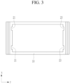
- FIG. 3 is a top plane view schematically showing the battery housing of FIG. 2 .
- FIG. 4 is a cross-sectional view along line A-A of the battery housing of FIG. 2 .
- a battery pack 100 may include, a battery housing 10 having an internal receiving space, a plurality of battery cells 11 accommodated inside the internal receiving space of the battery housing 10 and arranged in a first (arrangement) direction in the internal receiving space, and an upper cover 30 configured to cover an upper portion of the battery housing 10, where a guide portion 20 may be formed on an inner wall surface of the battery housing 10 to guide insertion of the plurality of battery cells into the internal receiving space.
- the battery housing 10 is configured to internally accommodate the plurality of battery cells 11, and the plurality of battery cells 11 may be accommodated while arranged in the first direction. That is, the plurality of battery cells 11 may be accommodated inside battery housing 10, without using a separate side surface frame (not shown).
- a cell barrier (not shown) may also be installed inside battery housing 10, such that the plurality of battery cells 11 may be partitioned.
- the cell barrier may be an insulation plate that partitions the internal receiving space of the battery housing 10 into a plurality of portions.
- the plurality of battery cells 11 may be aligned in the first direction (y-axis direction) in the battery housing 10.
- the guide portion 20 may be configured to guide insertion of the plurality of battery cells 11 into the internal receiving space formed in the battery housing 10.
- a clamping portion 110 may include a first gripper 111 and a second gripper 113.
- the guide portion 20 may be formed on the inner wall surface of the battery housing 10 and may guide insertion of the first gripper 111 and the second gripper 113 into the internal receiving space formed in the battery housing 10.
- the guide portion 20 may be formed on a pair of opposing side inner wall surfaces of the battery housing 10, and the plurality of battery cells 11 may be interposed between the pair of opposing side inner wall surfaces.
- the guide portion 20 may be a guide groove formed on the pair of opposing side inner wall surfaces of the battery housing 10, and the plurality of battery cells 11 may be interposed between the pair of opposing side inner wall surfaces.
- the same reference numeral is assigned to the guide portion and the guide groove.
- a guide groove 20 formed on the inner wall surface of the battery housing 10 may be configured to guide insertion of the clamping portion 110 into the battery housing 10 while clamping the plurality of battery cells 11 during the manufacturing process of the battery pack.
- the guide groove 20 may include a first guide groove 21 formed on an inner wall surface of a first side of the pair of opposing side inner wall surfaces of the battery housing 10, and a second guide groove 23 formed on inner wall surface of a second side of the pair of opposing side inner wall surfaces of the battery housing 10.
- the first guide groove 21 may be formed in a height direction of the inner wall surface of the first side of the battery housing 10.
- the first guide groove 21 may have a first polygonal groove shape recessed into the inner wall surface of the first side of the battery housing 10.
- the first guide groove 21 may be include a pair of grooves spaced apart from each other on the inner wall surface of the first side of the battery housing 10.
- the second guide groove 23 may be formed in the height direction of an inner wall surface of a second side of the battery housing 10.
- the second guide groove 23 may have a second polygonal groove shape recessed into the inner wall surface of the second side of the battery housing 10.
- the second guide groove 23 may include a pair of grooves spaced apart from each other on the inner wall surface of the second side of the battery housing 10.
- the first and second guide grooves 21 and 23 may have the same or similar shapes, and although the polygonal groove shape is taken as an example, it is not necessarily limited thereto, and the first and second guide grooves 21 and 23 may have a round groove shape to accommodate the shape of the gripper of the clamping portion 110.
- the upper cover 30 may be detachably installed on the upper portion of the battery housing 10 and may be detachably coupled by a fastening member such as a bolt member.
- both opposed sides of the plurality of battery cells 11 may be clamped by using the gripper, and during the process of inserting the clamped plurality of battery cells 11 into the battery housing 10, interference of the gripper with the battery housing 10 may be reduced. Therefore, manufacturing quality is improved when the plurality of battery cells 11 are installed inside battery housing 10 and stably aligned in the first direction.
- FIG. 5 is a side view schematically showing an apparatus for manufacturing a battery pack according to a first embodiment of the present disclosure.
- the reference numerals that is the same as in FIG. 1 to FIG. 4 may indicate the same or similar member of the same or similar function.
- components having the same reference numeral are not redundantly described in detail.
- an apparatus for manufacturing a battery pack 200 by inserting a plurality of battery cells 11 into the battery housing 10 may include the clamping portion 110 including the first gripper 111 configured to be inserted into the first guide groove 21 of the battery housing 10 and configured to pressurize a first side of the plurality of battery cells 11 and the second gripper 113 configured to be inserted into the second guide groove 23 and configured to pressurize a second side of the plurality of battery cells 11.
- the clamping portion 110 may be configured to insert the plurality of battery cells 11 into the internal receiving space of the battery housing 10.
- the apparatus further includes a pressurizer 120 configured to pressurize upper portions of the plurality of battery cells 11 inserted into the battery housing 10 and align the plurality of battery cells 11.
- the clamping portion 110 may be configured to insert the plurality of battery cells 11 into the battery housing 10 in an aligned state, and may be configured to insert the plurality of battery cells 11 into the battery housing 10 while pressurizing opposite sides of the plurality of battery cells 11.
- the clamping portion 110 may include the first gripper 111 configured to pressurize the first side of the plurality of battery cells 11, the second gripper 113 configured to pressurize the second side of the plurality of battery cells 11, and a driver 115 configured to provide a driving force to the first gripper 111 and the second gripper 113.
- the first gripper 111 may be configured to pressurizing a first side of the plurality of aligned battery cells 11, by the operation of the driver 115.
- the first gripper 111 may be inserted into the first guide groove 21 formed on the inner wall surface of the battery housing 10.
- the first gripper 111 may be inserted into the battery housing 10 by the guide operation of the first guide groove 21 and the plurality of battery cells 11 may be stably inserted into the battery housing 10.
- the second gripper 113 may be configured to pressurize the second side of the plurality of aligned battery cells 11.
- the second side is opposite to the first side on which the first gripper 111 is located.
- the first gripper 111 and the second gripper 113 may be configured to be lifted by operation of an actuator (not shown) installed on a lifting frame (not shown).
- the driver 115 may be connected to the first gripper 111 and the second gripper 113, and the driver 115 may be configured to provide a pressurizing force to the plurality of battery cells 11.
- the driver 115 may be a cylinder member configured to provide a pressurizing force to the plurality of battery cells 11.
- the cylinder member may be configured to be operated pneumatically or hydraulically.
- the pressurizer 120 may be configured to pressurize the upper portions of the plurality of battery cells 11 inserted into the battery housing 10 by the clamping portion 110.
- the pressurizer 120 may be configured to be liftable above the battery housing 10 and may include a pressurizing block 121 configured to pressurize the upper portions of the plurality of battery cells 11 when the pressurizer 120 is lowered to the plurality of battery cells 11.
- a lift driver 123 may be configured to provide a lifting force to the pressurizing block 121.
- a lower surface of the pressurizing block 121 may be a flat surface, and may be configured to pressurize upper portions of the battery cells 11 to correct misalignment of the plurality of battery cells 11 inserted into the battery housing 10.
- the pressurizing block 121 may be connected to the lift driver 123 which can lift and lower the pressurizing block 121 to pressurize the upper portions of the plurality of battery cells 11.
- the lift driver 123 may be a cylinder member having a rod connected to an upper portion of the pressurizing block 121 to provide a lifting force.
- the cylinder member may be configured to be operated pneumatically or hydraulically.
- a plurality of battery cells 11 may be stably inserted into the battery housing by operation of the guide portion 20 while the plurality of battery cells 11 are clamped by the clamping portion. As such, stable manufacturing of the battery pack and improved durability of the manufactured battery pack is achieved.
- FIG. 8 is a cross-sectional view schematically showing a friction pad attached to a pressurizer of an apparatus for manufacturing a battery pack according to a second embodiment of the present disclosure.
- the reference numerals that are the same as in FIG. 1 to FIG. 7 indicate the same or similar members having the same or similar function.
- components having the same reference numerals are not redundantly described in detail.
- a friction pad 210 may be attached to a bottom surface of the pressurizing block 121 of an apparatus for manufacturing a battery pack 330.
- the friction pad 210 may be attached to reduce formation of contact damage while the pressurizing block 121 is lowered to contact the upper portion of the battery cell 11. As such, by the attachment of the friction pad 210, the durability of the manufactured battery pack may be improved.
- battery housing 11 battery cell 20: guide portion, guide groove 21: first guide groove 23: second guide groove 30: upper cover 100: a battery pack 110: clamping portion 111: first gripper 113: second gripper 115: driver 120: pressurizer 121: pressurizing block 123: lift driver 210: friction pad
Landscapes
- Chemical & Material Sciences (AREA)
- Chemical Kinetics & Catalysis (AREA)
- Electrochemistry (AREA)
- General Chemical & Material Sciences (AREA)
- Engineering & Computer Science (AREA)
- Manufacturing & Machinery (AREA)
- Aviation & Aerospace Engineering (AREA)
- Life Sciences & Earth Sciences (AREA)
- Sustainable Development (AREA)
- Sustainable Energy (AREA)
- Power Engineering (AREA)
- Transportation (AREA)
- Mechanical Engineering (AREA)
- Battery Mounting, Suspending (AREA)
Abstract
A battery pack may include a battery housing having an internal receiving space, a plurality of battery cells accommodated inside the internal receiving space of the battery housing, and arranged in a first direction, an upper cover configured to cover an upper portion of the battery housing, where a guide portion may be formed on an inner wall surface of the battery housing to guide insertion of the plurality of battery cells into the internal receiving space.
Description
- The present disclosure relates to a battery pack and an apparatus for manufacturing a battery pack, providing stable insertion and alignment of a plurality of battery cells in a battery housing. The present disclosure further relates to a method of manufacturing a battery pack.
- Secondary batteries are used in devices such as mobile devices, auxiliary electric power devices, or the like.
- Secondary batteries are also attracting attention as the main power source for electric vehicles, hybrid electric vehicles, and plug-in hybrid electric vehicles, which have been proposed as an alternative to solve various problems such as air pollution of conventional gasoline or diesel vehicles.
- Due to the need for high-output, large-capacity batteries in electric vehicles, and the like, may use battery modules in which multiple battery cells are stacked and then electrically connected in series and parallel.
- A battery module includes a plurality of stacked battery cells, and terminals exposed at both ends of each battery cell are electrically connected to provide high voltage.
- Battery module pack housings are manufactured using various construction methods at sizes to suit the shape and pack capacity. These battery packs are manufactured by removing module components and inserting a plurality of battery cells into the battery housing to increase internal space efficiency and energy density.
- However, there is a problem in that it is not easy to insert a plurality of battery cells into the battery housing, and they may be inserted in a misaligned configuration, which may reduce durability and manufacturing efficiency.
- The present disclosure provides a battery pack and an apparatus for manufacturing a battery pack having accurately aligned battery cells without an interference with an inner wall surface of a battery housing during the process of inserting a plurality of battery cells into a battery housing.
- A battery pack may include a battery housing having an internal receiving space, a plurality of battery cells accommodated in the internal receiving space of the battery housing, and arranged in an arrangement direction, an upper cover configured to cover an upper portion of the battery housing, where a guide portion may be formed on an inner wall surface of the battery housing to guide insertion of the plurality of battery cells into the internal receiving space.
- The guide portion may be formed on a pair of opposing side inner wall surfaces of the battery housing, and the plurality of battery cells are interposed between the pair of opposing side inner wall surfaces.
- The guide portion may include a guide groove that is formed on one of the inner wall surfaces of the battery housing.
- The guide groove may include a first guide groove formed on an inner wall surface of a first side of the pair of opposing side inner wall surfaces of the battery housing, and a second guide groove formed on an inner wall surface of a second side of the pair of opposing side inner wall surfaces.
- The first guide groove may have a polygonal groove shape formed in a height direction of the battery housing, formed on the inner wall surface of the first side, and internally provided with an inserter.
- The second guide groove may be in a polygonal groove shape formed in the height direction of the battery housing, formed on the inner wall surface of the second side, and internally provided with the inserter.
- An apparatus for manufacturing a battery pack by inserting the plurality of battery cells inside battery housing, the apparatus includes a clamping portion including a first gripper configured to be inserted into the battery housing and configured to pressurize a first side of the plurality of battery cells, and a second gripper configured to be inserted into the battery housing and configured to pressurize a second side of the plurality of battery cells, wherein the clamping portion is configured to insert the plurality of battery cells into the internal receiving space of the battery housing, and a pressurizer configured to pressurize upper portions of the plurality of battery cells inserted into the battery housing and thereby align the plurality of battery cells.
- The clamping portion may include the first gripper configured to pressurize the first side of the plurality of battery cells, and configured to be inserted inside the first guide groove formed on an inner wall surface of a first side of the battery housing, the second gripper configured to pressurize the second side of the plurality of battery cells, and configured to be inserted inside the second guide groove formed on an inner wall surface of the second side opposed to the first side of the battery housing, and a driver configured to provide a driving force to the first gripper and the second gripper.
- The driver may be a cylinder member having a rod connected to the first gripper and the second gripper.
- The pressurizer may include a pressurizing block configured to be liftable above the battery housing, and configured to be lowered to pressurize the upper portions of the plurality of battery cells, and a lift driver configured to provide a lifting force to the pressurizing block.
- The lift driver may be a cylinder member having a rod connected to the pressurizing block to provide lifting force.
- A friction pad may be attached to a bottom surface of the pressurizing block.
- The present disclosure further provides a method of manufacturing a battery pack, the method comprising clamping a plurality of battery cells with a first gripper and a second gripper, inserting the plurality of battery cells into an internal receiving space of a battery housing, and pressurizing an upper portion of the plurality of battery cells inserted into the battery housing to align the plurality of battery cells.
- In some embodiments, inserting the plurality of battery cells into an internal receiving space of the battery housing comprises inserting the first gripper inside a first guide groove formed on an inner wall surface of a first side of the battery housing, and inserting the second gripper inside a second guide groove formed on an inner wall surface of a second side of the battery housing, the second side being opposite to the first side.
- In some embodiments, pressurizing the upper portion of the plurality of battery cells inserted into the battery housing to align the plurality of battery cells comprises lowering a pressurizing block to contact the upper portions of the plurality of battery cells.
- In some embodiments, a friction pad is attached to a bottom surface of the pressurizing block.
- According to some embodiments, stable insertion of a plurality of battery cells into the battery housing may be possible by the guide operation of the guide portion while the plurality of battery cells are being clamped by a clamping portion, and stable manufacturing of the battery pack and improved durability of the manufactured battery pack may be achieved.
-
-
FIG. 1 is a perspective view schematically showing a battery pack according to an embodiment. -
FIG. 2 is a perspective view schematically showing a battery housing according to an embodiment. -
FIG. 3 is a top plan view schematically showing the battery housing ofFIG. 2 . -
FIG. 4 is a cross-sectional view along line A-A of the battery housing ofFIG. 2 . -
FIG. 5 is a side view schematically showing an apparatus for manufacturing a battery pack according to a first embodiment of the present disclosure. -
FIG. 6 is a cross-sectional view schematically showing a state in which a plurality of battery cells is inserted inside battery housing by first and second grippers of an apparatus for manufacturing a battery pack ofFIG. 5 . -
FIG. 7 is a cross-sectional view schematically showing a state in which an upper portion of a plurality of battery cells inserted inside battery housing ofFIG. 6 is pressurized by a pressurizer. -
FIG. 8 is a cross-sectional view schematically showing a state in which a friction pad is attached to a pressurizer of an apparatus for manufacturing a battery pack according to a second embodiment of the present disclosure. - Hereinafter, the present disclosure will be described more fully with reference to the accompanying drawings, in which embodiments of the disclosure are shown. As those skilled in the art would realize, the described embodiments may be modified in various different ways, all without departing from the scope of the present disclosure. The drawings and description are to be regarded as illustrative in nature and not restrictive. Like reference numerals designate like elements throughout the specification.
-
FIG. 1 is a perspective view schematically showing a battery pack according to an embodiment.FIG. 2 is a perspective view schematically showing a battery housing according to an embodiment.FIG. 3 is a top plane view schematically showing the battery housing ofFIG. 2 .FIG. 4 is a cross-sectional view along line A-A of the battery housing ofFIG. 2 . - As shown in
FIG. 1 to FIG. 4 , abattery pack 100 according to an embodiment may include, abattery housing 10 having an internal receiving space, a plurality ofbattery cells 11 accommodated inside the internal receiving space of thebattery housing 10 and arranged in a first (arrangement) direction in the internal receiving space, and anupper cover 30 configured to cover an upper portion of thebattery housing 10, where aguide portion 20 may be formed on an inner wall surface of thebattery housing 10 to guide insertion of the plurality of battery cells into the internal receiving space. - The
battery housing 10 is configured to internally accommodate the plurality ofbattery cells 11, and the plurality ofbattery cells 11 may be accommodated while arranged in the first direction. That is, the plurality ofbattery cells 11 may be accommodated insidebattery housing 10, without using a separate side surface frame (not shown). - A cell barrier (not shown) may also be installed inside
battery housing 10, such that the plurality ofbattery cells 11 may be partitioned. The cell barrier may be an insulation plate that partitions the internal receiving space of thebattery housing 10 into a plurality of portions. - The plurality of
battery cells 11 may be aligned in the first direction (y-axis direction) in thebattery housing 10. - The
guide portion 20 may be configured to guide insertion of the plurality ofbattery cells 11 into the internal receiving space formed in thebattery housing 10. - A
clamping portion 110 may include afirst gripper 111 and asecond gripper 113. Theguide portion 20 may be formed on the inner wall surface of thebattery housing 10 and may guide insertion of thefirst gripper 111 and thesecond gripper 113 into the internal receiving space formed in thebattery housing 10. - The
guide portion 20 may be formed on a pair of opposing side inner wall surfaces of thebattery housing 10, and the plurality ofbattery cells 11 may be interposed between the pair of opposing side inner wall surfaces. - As a non-limiting example, the
guide portion 20 may be a guide groove formed on the pair of opposing side inner wall surfaces of thebattery housing 10, and the plurality ofbattery cells 11 may be interposed between the pair of opposing side inner wall surfaces. Hereinafter, the same reference numeral is assigned to the guide portion and the guide groove. - As such, a
guide groove 20 formed on the inner wall surface of thebattery housing 10 may be configured to guide insertion of theclamping portion 110 into thebattery housing 10 while clamping the plurality ofbattery cells 11 during the manufacturing process of the battery pack. - In more detail, the
guide groove 20 may include afirst guide groove 21 formed on an inner wall surface of a first side of the pair of opposing side inner wall surfaces of thebattery housing 10, and asecond guide groove 23 formed on inner wall surface of a second side of the pair of opposing side inner wall surfaces of thebattery housing 10. - The
first guide groove 21 may be formed in a height direction of the inner wall surface of the first side of thebattery housing 10. Thefirst guide groove 21 may have a first polygonal groove shape recessed into the inner wall surface of the first side of thebattery housing 10. - The
first guide groove 21 may be include a pair of grooves spaced apart from each other on the inner wall surface of the first side of thebattery housing 10. - The
second guide groove 23 may be formed in the height direction of an inner wall surface of a second side of thebattery housing 10. Thesecond guide groove 23 may have a second polygonal groove shape recessed into the inner wall surface of the second side of thebattery housing 10. - The
second guide groove 23 may include a pair of grooves spaced apart from each other on the inner wall surface of the second side of thebattery housing 10. - The first and
second guide grooves second guide grooves portion 110. - The
upper cover 30 may be detachably installed on the upper portion of thebattery housing 10 and may be detachably coupled by a fastening member such as a bolt member. - As described above, according to the
battery pack 100 of the present embodiment, during the manufacturing process, both opposed sides of the plurality ofbattery cells 11 may be clamped by using the gripper, and during the process of inserting the clamped plurality ofbattery cells 11 into thebattery housing 10, interference of the gripper with thebattery housing 10 may be reduced. Therefore, manufacturing quality is improved when the plurality ofbattery cells 11 are installed insidebattery housing 10 and stably aligned in the first direction. -
FIG. 5 is a side view schematically showing an apparatus for manufacturing a battery pack according to a first embodiment of the present disclosure. The reference numerals that is the same as inFIG. 1 to FIG. 4 may indicate the same or similar member of the same or similar function. Hereinafter, components having the same reference numeral are not redundantly described in detail. - As shown in
FIG. 5 , an apparatus for manufacturing abattery pack 200 by inserting a plurality ofbattery cells 11 into thebattery housing 10 may include the clampingportion 110 including thefirst gripper 111 configured to be inserted into thefirst guide groove 21 of thebattery housing 10 and configured to pressurize a first side of the plurality ofbattery cells 11 and thesecond gripper 113 configured to be inserted into thesecond guide groove 23 and configured to pressurize a second side of the plurality ofbattery cells 11. The clampingportion 110 may be configured to insert the plurality ofbattery cells 11 into the internal receiving space of thebattery housing 10. The apparatus further includes apressurizer 120 configured to pressurize upper portions of the plurality ofbattery cells 11 inserted into thebattery housing 10 and align the plurality ofbattery cells 11. - The clamping
portion 110 may be configured to insert the plurality ofbattery cells 11 into thebattery housing 10 in an aligned state, and may be configured to insert the plurality ofbattery cells 11 into thebattery housing 10 while pressurizing opposite sides of the plurality ofbattery cells 11. - For example, the clamping
portion 110 may include thefirst gripper 111 configured to pressurize the first side of the plurality ofbattery cells 11, thesecond gripper 113 configured to pressurize the second side of the plurality ofbattery cells 11, and adriver 115 configured to provide a driving force to thefirst gripper 111 and thesecond gripper 113. - The
first gripper 111 may be configured to pressurizing a first side of the plurality of alignedbattery cells 11, by the operation of thedriver 115. - During the process of inserting the plurality of
battery cells 11 into thebattery housing 10, thefirst gripper 111 may be inserted into thefirst guide groove 21 formed on the inner wall surface of thebattery housing 10. - For example, the
first gripper 111 may be inserted into thebattery housing 10 by the guide operation of thefirst guide groove 21 and the plurality ofbattery cells 11 may be stably inserted into thebattery housing 10. - The
second gripper 113 may be configured to pressurize the second side of the plurality of alignedbattery cells 11. The second side is opposite to the first side on which thefirst gripper 111 is located. - The
first gripper 111 and thesecond gripper 113 may be configured to be lifted by operation of an actuator (not shown) installed on a lifting frame (not shown). - The
driver 115 may be connected to thefirst gripper 111 and thesecond gripper 113, and thedriver 115 may be configured to provide a pressurizing force to the plurality ofbattery cells 11. - The
driver 115 may be a cylinder member configured to provide a pressurizing force to the plurality ofbattery cells 11. The cylinder member may be configured to be operated pneumatically or hydraulically. - The
pressurizer 120 may be configured to pressurize the upper portions of the plurality ofbattery cells 11 inserted into thebattery housing 10 by the clampingportion 110. - For example, the
pressurizer 120 may be configured to be liftable above thebattery housing 10 and may include apressurizing block 121 configured to pressurize the upper portions of the plurality ofbattery cells 11 when thepressurizer 120 is lowered to the plurality ofbattery cells 11. Alift driver 123 may be configured to provide a lifting force to the pressurizingblock 121. - A lower surface of the pressurizing
block 121 may be a flat surface, and may be configured to pressurize upper portions of thebattery cells 11 to correct misalignment of the plurality ofbattery cells 11 inserted into thebattery housing 10. - The pressurizing
block 121 may be connected to thelift driver 123 which can lift and lower thepressurizing block 121 to pressurize the upper portions of the plurality ofbattery cells 11. - The
lift driver 123 may be a cylinder member having a rod connected to an upper portion of the pressurizingblock 121 to provide a lifting force. The cylinder member may be configured to be operated pneumatically or hydraulically. - As described above, according to an apparatus for manufacturing a
battery pack 200 of the present disclosure, a plurality ofbattery cells 11 may be stably inserted into the battery housing by operation of theguide portion 20 while the plurality ofbattery cells 11 are clamped by the clamping portion. As such, stable manufacturing of the battery pack and improved durability of the manufactured battery pack is achieved. -
FIG. 8 is a cross-sectional view schematically showing a friction pad attached to a pressurizer of an apparatus for manufacturing a battery pack according to a second embodiment of the present disclosure. The reference numerals that are the same as inFIG. 1 to FIG. 7 indicate the same or similar members having the same or similar function. Hereinafter, components having the same reference numerals are not redundantly described in detail. - As shown in
FIG. 8 , afriction pad 210 according to a second embodiment of the present disclosure may be attached to a bottom surface of the pressurizingblock 121 of an apparatus for manufacturing a battery pack 330. - The
friction pad 210 may be attached to reduce formation of contact damage while the pressurizingblock 121 is lowered to contact the upper portion of thebattery cell 11. As such, by the attachment of thefriction pad 210, the durability of the manufactured battery pack may be improved. - While this disclosure has been described in connection with what is presently considered to be practical embodiments, it is to be understood that the disclosure is not limited to the disclosed embodiments, but, on the contrary, is intended to cover various modifications and equivalent arrangements included within the scope of the appended claims.
-
10: battery housing 11: battery cell 20: guide portion, guide groove 21: first guide groove 23: second guide groove 30: upper cover 100: a battery pack 110: clamping portion 111: first gripper 113: second gripper 115: driver 120: pressurizer 121: pressurizing block 123: lift driver 210: friction pad
Claims (15)
- A battery pack (100, 200, 330), comprising:a battery housing (10) including an internal receiving space;a plurality of battery cells (11) accommodated in the internal receiving space of the battery housing (10) and arranged in an arrangement direction;an upper cover (30) configured to cover an upper portion of the battery housing (10),wherein a guide portion is formed on an inner wall surface of the battery housing (10) to guide insertion of the plurality of battery cells (11) into the internal receiving space.
- The battery pack (100, 200, 330) of claim 1, wherein the guide portion is formed on a pair of opposing side inner wall surfaces of the battery housing (10), and the plurality of battery cells (11) are interposed between the pair of opposing side inner wall surfaces.
- The battery pack (100, 200, 330) of claim 2, wherein the guide portion includes a guide groove that is formed on one of the side inner wall surface of the battery housing (10).
- The battery pack (100, 200, 330) of claim 3, wherein the guide groove is a first guide groove (21) formed on an inner wall surface of a first side of the pair of opposing side inner wall surfaces of the battery housing (10), and
wherein the guide portion includes a second guide groove (23) formed on an inner wall surface of a second side of the pair of opposing side inner wall surfaces of the battery housing (10). - The battery pack (100, 200, 330) of claim 4, wherein the first guide groove (21) has a polygonal groove shape formed in a height direction of the battery housing (10), is formed on the inner wall surface of the first side, and is internally provided with an inserter.
- The battery pack (100, 200, 330) of claim 5, wherein the second guide groove (23) has a polygonal groove shape formed in the height direction of the battery housing (10), is formed on the inner wall surface of the second side, and is internally provided with the inserter.
- An apparatus for manufacturing a battery pack (100, 200, 330) by inserting the plurality of battery cells (11) inside the battery housing (10) of claim 1, the apparatus comprising:a clamping portion (110) comprising a first gripper (111) inserted into the battery housing (10) and configured to pressurize a first side of the plurality of battery cells (11), and a second gripper (113) inserted into the battery housing (10) and configured to pressurize a second side of the plurality of battery cells (11), wherein the clamping portion (110) is configured to insert the plurality of battery cells (11) into the internal receiving space of the battery housing (10); anda pressurizer (120) configured to pressurize upper portions of the plurality of battery cells (11) inserted into the battery housing (10) and thereby align the plurality of battery cells (11).
- The apparatus of claim 7, wherein the first gripper (111) is configured to pressurize the first side of the plurality of battery cells (11), and inserted inside a first guide groove (21) formed on an inner wall surface of a first side of the battery housing (10),wherein the second gripper (113) is configured to pressurize the second side of the plurality of battery cells (11), and inserted inside a second guide groove (23) formed on an inner wall surface of a second side opposite to the first side of the battery housing (10), with the plurality of battery cells (11) being interposed between the first side and the second side, andwherein the clamping portion (110) further comprises a driver (115) configured to a driving force to the first gripper (111) and the second gripper (113).
- The apparatus of claim 8, wherein the driver (115) is a cylinder member having a rod connected to the first gripper (111) and the second gripper (113).
- The apparatus of claim 9, wherein the pressurizer (120) comprises:a pressurizing block (121) configured to be liftable above the battery housing (10), and configured to pressurize the upper portions of the plurality of battery cells (11) when lowered; anda lift driver (123) configured to provide a lifting force to the pressurizing block (121).
- The apparatus of claim 10, wherein the lift driver (123) is a cylinder member having a rod connected to the pressurizing block (121) to provide a lifting force.
- The apparatus of claim 11, wherein a friction pad (210) is attached to a bottom surface of the pressurizing block (121).
- A method of manufacturing a battery pack (100, 200, 330), the method comprising:clamping a plurality of battery cells (11) with a first gripper (111) and a second gripper (113);inserting the plurality of battery cells (11) into an internal receiving space of a battery housing (10); andpressurizing an upper portion of the plurality of battery cells (11) inserted into the battery housing (10) to align the plurality of battery cells (11).
- The method of claim 13, wherein inserting the plurality of battery cells (11) into the internal receiving space of a battery housing (10) comprises:inserting the first gripper (111) inside a first guide groove (21) formed on an inner wall surface of a first side of the battery housing (10); andinserting the second gripper (113) inside a second guide groove (23) formed on an inner wall surface of a second side of the battery housing (10), the second side being opposite to the first side.
- The method of claims 13 or 14, wherein pressurizing the upper portion of the plurality of battery cells (11) inserted into the battery housing (10) to align the plurality of battery cells (11) comprises lowering a pressurizing block (121) to contact the upper portions of the plurality of battery cells (11).
Applications Claiming Priority (1)
| Application Number | Priority Date | Filing Date | Title |
|---|---|---|---|
| KR1020230173746A KR20250084737A (en) | 2023-12-04 | 2023-12-04 | Battery pack and apparatus for manufacturing battery pack |
Publications (1)
| Publication Number | Publication Date |
|---|---|
| EP4567948A1 true EP4567948A1 (en) | 2025-06-11 |
Family
ID=93741592
Family Applications (1)
| Application Number | Title | Priority Date | Filing Date |
|---|---|---|---|
| EP24216249.3A Pending EP4567948A1 (en) | 2023-12-04 | 2024-11-28 | Battery pack, method of manufacturing such and apparatus for manufacturing a battery pack |
Country Status (4)
| Country | Link |
|---|---|
| US (1) | US20250183461A1 (en) |
| EP (1) | EP4567948A1 (en) |
| KR (1) | KR20250084737A (en) |
| CN (1) | CN120109398A (en) |
Citations (2)
| Publication number | Priority date | Publication date | Assignee | Title |
|---|---|---|---|---|
| US20230307762A1 (en) * | 2022-03-23 | 2023-09-28 | Ford Global Technologies, Llc | Traction battery pack assembling method |
| US20230307758A1 (en) * | 2022-03-23 | 2023-09-28 | Ford Global Technologies, Llc | Traction battery pack enclosure and traction battery pack assembly method |
-
2023
- 2023-12-04 KR KR1020230173746A patent/KR20250084737A/en active Pending
-
2024
- 2024-11-12 US US18/944,227 patent/US20250183461A1/en active Pending
- 2024-11-20 CN CN202411660614.2A patent/CN120109398A/en active Pending
- 2024-11-28 EP EP24216249.3A patent/EP4567948A1/en active Pending
Patent Citations (2)
| Publication number | Priority date | Publication date | Assignee | Title |
|---|---|---|---|---|
| US20230307762A1 (en) * | 2022-03-23 | 2023-09-28 | Ford Global Technologies, Llc | Traction battery pack assembling method |
| US20230307758A1 (en) * | 2022-03-23 | 2023-09-28 | Ford Global Technologies, Llc | Traction battery pack enclosure and traction battery pack assembly method |
Also Published As
| Publication number | Publication date |
|---|---|
| US20250183461A1 (en) | 2025-06-05 |
| CN120109398A (en) | 2025-06-06 |
| KR20250084737A (en) | 2025-06-11 |
Similar Documents
| Publication | Publication Date | Title |
|---|---|---|
| US10559793B2 (en) | Battery array retention method and assembly | |
| EP2490276B1 (en) | Battery module with superior structural stability | |
| KR20220134502A (en) | Battery pack structure of vehicle | |
| JP6271178B2 (en) | Battery device, electric vehicle and power storage device including the battery device | |
| CN104953059A (en) | Support structure for battery cells within traction battery assembly | |
| US20230307758A1 (en) | Traction battery pack enclosure and traction battery pack assembly method | |
| CN116487719A (en) | Battery cell end plate insulating cover assembly production line | |
| EP4567948A1 (en) | Battery pack, method of manufacturing such and apparatus for manufacturing a battery pack | |
| CN207651603U (en) | Battery pack palletizer | |
| US20240363891A1 (en) | Battery module stacking device and method, and battery production system | |
| US12603373B2 (en) | Traction battery pack assembling method | |
| US20230307775A1 (en) | Traction battery pack assembling method | |
| US20230307771A1 (en) | Traction battery pack electronics support plate and electronics support method | |
| US20230302887A1 (en) | Traction battery packs with cell-to-pack battery systems housed within irregularly shaped enclosures | |
| CN116845455A (en) | Traction battery pack shell and traction battery pack assembly method | |
| US12525637B2 (en) | Traction battery pack assembling method | |
| KR20250167413A (en) | Batery cell module assembly and manufacturing method tehrof | |
| US20230307776A1 (en) | Traction battery pack assembling method | |
| CN207651604U (en) | The full-automatic palletizer of battery pack | |
| US20240204333A1 (en) | Battery pack winged spacer assembly and battery cell spacing method | |
| CN220162259U (en) | Cell module clamping device and discharging equipment | |
| KR20250179498A (en) | Electrode supply equipment | |
| US20250319612A1 (en) | Cell stack gripping system and method | |
| US20230307687A1 (en) | Battery lift and transfer solutions for assembling traction battery packs | |
| KR102874966B1 (en) | Battery module and assembling method thereof |
Legal Events
| Date | Code | Title | Description |
|---|---|---|---|
| PUAI | Public reference made under article 153(3) epc to a published international application that has entered the european phase |
Free format text: ORIGINAL CODE: 0009012 |
|
| STAA | Information on the status of an ep patent application or granted ep patent |
Free format text: STATUS: REQUEST FOR EXAMINATION WAS MADE |
|
| 17P | Request for examination filed |
Effective date: 20241128 |
|
| AK | Designated contracting states |
Kind code of ref document: A1 Designated state(s): AL AT BE BG CH CY CZ DE DK EE ES FI FR GB GR HR HU IE IS IT LI LT LU LV MC ME MK MT NL NO PL PT RO RS SE SI SK SM TR |