EP4567853A1 - High speed circuit breaker comprising a movable magnetic shim in an air gap of a magnetic circuit - Google Patents
High speed circuit breaker comprising a movable magnetic shim in an air gap of a magnetic circuit Download PDFInfo
- Publication number
- EP4567853A1 EP4567853A1 EP23307137.2A EP23307137A EP4567853A1 EP 4567853 A1 EP4567853 A1 EP 4567853A1 EP 23307137 A EP23307137 A EP 23307137A EP 4567853 A1 EP4567853 A1 EP 4567853A1
- Authority
- EP
- European Patent Office
- Prior art keywords
- lever
- gap
- air
- rotation axis
- contact
- Prior art date
- Legal status (The legal status is an assumption and is not a legal conclusion. Google has not performed a legal analysis and makes no representation as to the accuracy of the status listed.)
- Pending
Links
Images



Classifications
-
- H—ELECTRICITY
- H01—ELECTRIC ELEMENTS
- H01H—ELECTRIC SWITCHES; RELAYS; SELECTORS; EMERGENCY PROTECTIVE DEVICES
- H01H71/00—Details of the protective switches or relays covered by groups H01H73/00 - H01H83/00
- H01H71/74—Means for adjusting the conditions under which the device will function to provide protection
- H01H71/7463—Adjusting only the electromagnetic mechanism
Definitions
- the present invention deals with a circuit breaker comprising:
- One known technology for the tripping system involves a magnetic circuit surrounding the first electrical contact and delimiting an air-gap, the tripping system comprising a core at least partly located in the air gap and intended to be subject to a magnetic force having a magnitude related to the current.
- a torsion spring and a cam item able to bend the spring are often used.
- the torsion spring applies an effort in order to prevent the rotation of a lever in the tripping system until the current exceeds the threshold.
- the cam allows increasing or decreasing the effort applied by the spring, which modifies the threshold.
- An aim of the invention is thus to provide a circuit breaker with an adjustable threshold that is more secure and cost efficient.
- the invention proposes a circuit breaker comprising:
- circuit breaker comprises one or several of the following features, taken in isolation or any technically feasible combination:
- the circuit breaker 10 comprises a chassis 12, a first contact 14, and a second contact 16.
- the circuit breaker 10 comprises an actuator mechanism 18 movable with respect to the chassis 12 at least between a closed position ( Figures 1 and 2 ), in which the first contact 14 and the second contact 16 are in electrical contact with each other and form an electrical circuit 20 in which a current C is intended to circulate, and a tripped position ( Figure 4 ), in which the first contact 14 and the second contact 16 are apart from each other.
- the circuit breaker 10 comprises a tripping system 22 adapted for preventing the actuator mechanism 18 from switching from the closed position to the tripped position as long as the current C does not exceed a threshold, and for allowing the actuator mechanism 18 to switch from the closed position to the tripped position when the current exceeds the threshold.
- the circuit breaker 10 is advantageously a high speed one, meaning that it is designed for tripping quickly enough in order to limit the short circuit current that is effectively reached.
- the circuit breaker 10 advantageously takes only a few milliseconds for switching from the closed position to the tripped position.
- the circuit breaker 10 comprises a setting system 24 ( Figure 2 ) adapted for setting the threshold.
- the circuit breaker 10 advantageously comprises an external envelope 26 (partly removed in Figure 1 ) surrounding its internal components and preventing outside objects or a person (not shown) to be in contact with its internal components.
- the electrical circuit 10 is for example adapted to stand a current C from 1200 A (amperes) to 5000 A.
- the first contact 14 for example comprises a first portion 14A extending in a longitudinal direction L and fixed to the chassis 12.
- the first contact 14 for example comprises a second portion 14B fixed to the actuator mechanism 18.
- the first portion 14A is rigid and the second portion 14B is flexible, in order to be moved away from the second contact when the actuator mechanism 18 moves from the closed position to the tripped position, or advantageously to an open position ( Figure 5 ) which will be described later.
- the second contact 16 extends for example parallel to the first portion, at a distance from the first portion advantageously in a transverse direction T perpendicular to the longitudinal direction L.
- the second portion 14B and the second contact 16 for example includes tips 27, 28 ( Figure 4 ) adapted for electrical contact with each other and for withstanding arc breaking constraints.
- the actuator mechanism 18 comprises a first lever 30, a first biasing system 32, and in the example an actuator 34.
- the first lever 30 is rotatably mounted around a first rotation axis X1, in the example on a rod 34A of the actuator 34.
- the first lever 30 has a first end 30A fixed to the second portion 14B of the first contact 14.
- the first lever 30 has a second end 30B opposite the first end 30A and adapted for abutting in the closed position against an abutment surface 36 defined by the tripping system 22 in the closed position.
- the first lever 30 is for example made of aluminum.
- the second end 30B is on the side opposite the first end 30A with respect to the first rotation axis X1 along the first lever 30.
- the second end 30B of first lever 30 advantageously comprises a roll 38 adapted for rolling on the abutment surface 36.
- the first rotation axis X1 is for example orthogonal to the longitudinal direction Land to the transverse direction T.
- the first rotation axis X1 is for example perpendicular to the first lever 30 and crosses the first lever in a median part 40 ( Figure 5 ) of the first lever.
- the first biasing system 32 for example comprises a spring 42 ( Figure 5 ) rotatably mounted on the first end 30A of the first lever 30.
- the first biasing system 32 is adapted for applying an actuating force F1 on the first end 30A of the first lever 30.
- the abutment surface 36 is adapted for preventing the actuating force F1 from rotating the first lever 30 around the first rotation axis X1 from the closed position to the tripped position.
- the actuator 34 is adapted for displacing the first rotation axis X1 with respect to the chassis 12, for example in translation along the longitudinal direction L, between the closed position and the open position.
- the tripping system 22 comprises a magnetic circuit 44 surrounding the first electrical contact 14 and delimiting a first air-gap 44A.
- the tripping system 22 comprises a core 46 at least partly located in the first air gap 44A and intended to be subject to a magnetic force F2 ( Figure 2 ) having a magnitude related to the current C.
- the tripping system 22 is for example adapted for moving the abutment surface 36 with respect to the chassis 12 so as to liberate the first lever 30 when the current C exceeds a threshold, the actuating force F2 rotating the first lever 30 around the first rotation axis X1 from the closed position to the tripped position as soon as the first lever is liberated.
- the tripping system 22 comprises a second lever 48, a second biasing system 50, and advantageously a third biasing system 52.
- the second lever 48 is rotatably mounted with respect to the chassis 12 around a second rotation axis X2.
- the second lever 48 has a first end 48A mechanically connected to the core 46, and a second end 48B opposite the first end 48A, the second end 48B defining the abutment surface 36.
- the second lever 48 advantageously comprises a first part 48C ( Figure 2 ) rotatably mounted with respect to the chassis 12 around the second rotation axis X2, and a second part 48D rotatably mounted on the first part around a third rotation axis X3 parallel to the second rotation axis X2,
- the second rotation axis X2 is for example parallel to the first rotation axis X1.
- the first part 48C comprises the first end 48A of the second lever 48.
- the second part 48D comprises the second end 48B of the second lever 48.
- the third rotation axis X3 is on the side opposite the first end 48A with respect to the second rotation axis X2 along the second lever 48.
- the third rotation axis X3 is for example parallel to the second rotation axis X2.
- the second part 48D is movable in rotation around the third rotation axis X3 in a first sense S1 with respect to the first part 48C between a work position ( Figures 1 and 2 ), and a bent position ( Figure 4 ).
- the second part 48D In the work position, intended to be occupied when the actuator mechanism 18 is in the closed position, the second part 48D abuts against the first part 48C and is prevented from rotating in a second sense S2 opposite the first sense S1.
- the second part 48D In the bent position, intended to be occupied when the actuator mechanism 18 in the tripped position or to allow the first lever 30 moving from the closed position to the open position, the second part 48D has rotated in the first sense S1 compared with the work position.
- the bent position provides flexibility to the second lever 48.
- the third biasing system 52 is advantageously adapted for biasing the second part 48D towards the work position.
- the third biasing system 52 for example comprises a coil spring 54 adapted for acting on the second part 48D of the second lever 48, in between the second rotation axis X2 and the third rotation axis X3.
- the core 46 is adapted for applying a tripping force F3 on the first end 48A, the tripping force F3 being related to the magnetic force F2 and intended to rotate the second lever 48 around the second rotation axis X2 in a first sense S1 so as to move the abutment surface 36 and liberate the first lever 30.
- the core 46 When seen in the longitudinal direction L, the core 46 for example has a trapezoidal shape flaring away from the first portion 14A of the first contact 14.
- the second biasing system 50 is adapted for applying a resisting force F4 on the second lever 48 so as to prevent rotation of the second lever around the second rotation axis X2 in the first sense S1, the tripping force F3 overcoming the resisting force F4 when the current C exceeds the threshold.
- the second biasing system 50 for example comprises a coil spring 56 and is advantageously devoid of any setting mechanism such as a cam system.
- the magnetic circuit 44 defines a second air-gap 44B ( Figure 3 ).
- the magnetic circuit 44 defines at least one magnetic loop 58, each the first air-gap 44A and the second air-gap 44B at least partly interrupting said loop.
- the first air-gap 44A and the second air-gap 44B can be located at any two locations of the same magnetic loop, in series or parallel.
- the magnetic circuit 44 defines only one loop 58.
- the magnetic circuit 44 for example comprises an air-gap 44C fully interrupting the loop 58, the first air-gap 44A being a first portion of the air-gap 44C, and the second air-gap 44B being a second portion of the air-gap 44C.
- the first air-gap 44A and the second air-gap 44B are in parallel in this case. Altogether the first air-gap 44A and the second air-gap 44B completely interrupt the loop 58.
- the magnetic circuit 44 surrounds the first portion 14A of the first contact 14 around the longitudinal direction L.
- the magnetic circuit 44 extends in a plane P perpendicular to the longitudinal direction L.
- the second air-gap 44B is delimited by two faces 60, 62 defined by the magnetic circuit 44 and parallel to each other.
- the two faces 60, 62 are for example parallel to the longitudinal direction L and to the transverse direction T.
- the setting system 24 comprises a magnetic shim 64 movable with respect to the magnetic circuit 44 between a plurality of positions not shown in which the shim 64 is at least partly located in the second air-gap 44B, the plurality of positions corresponding to a plurality of volumes V of the shim 64 within the second air-gap 44B and to a plurality of values of the magnetic force F2 applied to the core 46.
- the setting system 24 is advantageously adapted for setting the threshold over a large range of current C, for example from 1200 A to 5000 A.
- the magnetic shim 64 for example has two faces 70, 72 parallel to the two faces 60, 62 of the magnetic circuit 44.
- the magnetic shim 64 is advantageously movable with respect to the chassis 12 in translation, for example along the longitudinal direction L.
- the shim 64 comprises, or is made of magnetic metal.
- the shim 64 is advantageously adapted for changing the magnetic reluctance of the magnetic circuit 44.
- the shim 64 is a portion of the rack 66, more or less inserted in the second air-gap 44B.
- circuit breaker 10 The operation of the circuit breaker 10 stems from its structure and will now be briefly described.
- the actuator mechanism 18 is for example in the closed position ( Figure 1 and 2 ).
- the first contact 14 and the second contact 16 are in contact with each other and the current C below the threshold can circulate in the electrical circuit 20.
- the tripping system 22 prevents the actuator mechanism 18 from switching from the closed position to the tripped position.
- the second end 30B of the first lever 30 abuts against the abutment surface 36 of the tripping system 22.
- the actuator 34 displaces the first rotation axis X1 with respect to the chassis 12.
- the second end 30B of the first lever 30 keeps abutting on the abutment surface 36.
- the first lever 30 rotates with respect to the chassis 12 due to the actuating force F1 applied by the first biasing system 32 on the first end 30A of the first lever 30.
- the tripping system 22 allows the actuator mechanism 18 to switch from the closed position to the tripped position.
- the magnetic force F2 applied on the core 46 increases, so that the tripping force F3 applied by the core 46 on the first end 48A of the second lever 48 increases.
- the tripping forces F3 overcomes the resisting force F4 applied by the second biasing system 50, the second lever 48 rotates around the second rotation axis X2 with respect to the chassis 12.
- the abutment surface 36 moves such that the second end 30B of the first lever 30 does not abut any more on the abutment surface 36.
- the first lever 30 is then free to rotate around the first rotation axis X1 from the closed position to the tripped position.
- the second lever 48 bends around the third rotation axis X3 due to motion of the second end 30B of the first lever 30.
- the actuator mechanism 18 can be put from the tripped position to the open position by using the actuator 34 to displace the first rotation axis X1 towards the right in Figure 4 .
- the second end 30B of the first lever 30 comes back into contact with the abutment surface 36.
- the actuator mechanism 18 can be put in the closed position by using the actuator 34 to displace the first rotation axis X1 towards the left in Figure 5 .
- the shim 64 is moved with respect to the magnetic circuit 44 from one of its positions to another one, which changes the volume V of the shim 64 in the second air-gap 44B.
- This modifies the magnetic flux in the magnetic circuit 44, hence the magnetic force F2 applied to the core 46, for a same level of the current C.
- the shim 64 is moved by rotating the pinion 68, which translates the rack 66 longitudinally. The bigger the volume V of the shim 64 within the second air-gap 44B, the higher the threshold.
- the setting system 24 does not generate friction within the tripping system 22.
- the threshold is thus stable.
- the threshold can be easily set by moving the shim 64 from one position to another.
- the circuit breaker 10 is thus more secure and is cost efficient.
- the setting system 24 is advantageously adapted for modifying the threshold in a large range of current.
Landscapes
- Physics & Mathematics (AREA)
- Electromagnetism (AREA)
- Breakers (AREA)
Abstract
A circuit breaker comprising:
- a chassis, a first contact (14), and a second contact (16),
- an actuator mechanism (18) movable between a closed position, and a tripped position,
- a tripping system (22) comprising a magnetic circuit (44) surrounding the first contact and delimiting a first air-gap, and a core (46) at least partly located in the first air gap and subject to a magnetic force (F2), the tripping system being adapted for preventing the actuator mechanism from switching from the closed position to the tripped position as long a current in the contacts does not exceed a threshold,
- a setting system (24) for setting the threshold.
- a chassis, a first contact (14), and a second contact (16),
- an actuator mechanism (18) movable between a closed position, and a tripped position,
- a tripping system (22) comprising a magnetic circuit (44) surrounding the first contact and delimiting a first air-gap, and a core (46) at least partly located in the first air gap and subject to a magnetic force (F2), the tripping system being adapted for preventing the actuator mechanism from switching from the closed position to the tripped position as long a current in the contacts does not exceed a threshold,
- a setting system (24) for setting the threshold.
The magnetic circuit defines a second air-gap, the setting system comprising a magnetic shim (64) movable with respect to the magnetic circuit between a plurality of positions in which the shim is at least partly located in the second air-gap.
Description
- The present invention deals with a circuit breaker comprising:
- a chassis, a first contact, and a second contact,
- an actuator mechanism movable with respect to the chassis at least between a closed position, in which the first contact and the second contact are in electrical contact with each other and form an electrical circuit in which a current is intended to circulate, and a tripped position, in which the first contact and the second contact are apart from each other, and
- a tripping system adapted for preventing the actuator mechanism from switching from the closed position to the tripped position as long as the current does not exceed a threshold, and for allowing the actuator mechanism to switch from the closed position to the tripped position when the current exceeds the threshold.
- One known technology for the tripping system involves a magnetic circuit surrounding the first electrical contact and delimiting an air-gap, the tripping system comprising a core at least partly located in the air gap and intended to be subject to a magnetic force having a magnitude related to the current.
- In order to set the threshold, a torsion spring and a cam item able to bend the spring are often used. The torsion spring applies an effort in order to prevent the rotation of a lever in the tripping system until the current exceeds the threshold. The cam allows increasing or decreasing the effort applied by the spring, which modifies the threshold.
- However, the motions of the lever during operation of the circuit breaker lead to stress and friction between the different parts (spring, lever, shafts), which may cause a possible jamming of the tripping system and an unstable threshold during the lifetime of the circuit breaker. Such consequences require maintenance and create costs.
- Besides, with this technology, in order to cover a large range of possible thresholds, for example from 1200 A to 5000 A, typically three different tripping systems must be used.
- An aim of the invention is thus to provide a circuit breaker with an adjustable threshold that is more secure and cost efficient.
- To this end, the invention proposes a circuit breaker comprising:
- a chassis, a first contact, and a second contact,
- an actuator mechanism movable with respect to the chassis at least between a closed position, in which the first contact and the second contact are in electrical contact with each other and form an electrical circuit in which a current is intended to circulate, and a tripped position, in which the first contact and the second contact are apart from each other,
- a tripping system comprising a magnetic circuit surrounding the first contact and delimiting a first air-gap, the tripping system comprising a core at least partly located in the first air gap and intended to be subject to a magnetic force having a magnitude related to the current, the tripping system being adapted for preventing the actuator mechanism from switching from the closed position to the tripped position as long as the current does not exceed a threshold, and for allowing the actuator mechanism to switch from the closed position to the tripped position when the current exceeds the threshold, and
- a setting system adapted for setting the threshold,
- In other embodiments, the circuit breaker comprises one or several of the following features, taken in isolation or any technically feasible combination:
- the magnetic circuit defines at least one magnetic loop, each the first air-gap and the second air-gap at least partly interrupting said loop;
- the magnetic circuit comprises an air-gap fully interrupting the loop, the first air-gap being a first portion of the air-gap, and the second air-gap being a second portion of the air-gap;
- the second air-gap is delimited by two faces defined by the magnetic circuit and parallel to each other, the shim defining two faces parallel to the two faces of the magnetic circuit;
- the magnetic circuit surrounds a first portion of the first contact around a longitudinal direction, the shim being movable with respect to the chassis along the longitudinal direction;
- the setting system comprises: a rack fixed to the shim; and a pinion rotatably mounted with respect to the chassis and adapted for moving the rack in translation with respect to the chassis;
- the shim comprises, or is made of magnetic metal;
- the actuator mechanism comprises a first lever and a first biasing system, the first lever being rotatably mounted around a first rotation axis, the first contact comprising a first portion surrounded by the magnetic circuit, and a second portion, the second portion being flexible and fixed to the first lever, wherein: in the closed position, the first biasing system is adapted for applying an actuating force on a first end of the first lever, the first lever having a second end opposite the first end and adapted for abutting against an abutment surface defined by the tripping system in order to prevent the actuating force from rotating the first lever around the first rotation axis from the closed position to the tripped position; and the tripping system is adapted for moving the abutment surface with respect to the chassis so as to liberate the first lever when the current exceeds a threshold, the actuating force rotating the first lever around the first rotation axis from the closed position to the tripped position as soon as the first lever is liberated;
- the tripping system comprises a second lever and a second biasing system, the second lever being rotatably mounted with respect to the chassis around a second rotation axis, the second lever having a first end mechanically connected to the core, and a second end opposite the first end, the second end defining the abutment surface, wherein: the core is adapted for applying a tripping force on the first end, the tripping force being related to the magnetic force and intended to rotate the second lever around the second rotation axis in a first sense so as to move the abutment surface and liberate the first lever; and the second biasing system is adapted for applying a resisting force on the second lever so as to prevent rotation of the second lever around the second rotation axis in the first sense, the tripping force overcoming the resisting force when the current exceeds the threshold;
- the second biasing system comprises a coil spring;
- the second lever comprises: a first part rotatably mounted with respect to the chassis around the second rotation axis and comprising the first end of the second lever; and a second part rotatably mounted on said first part around a third rotation axis parallel to the second rotation axis, the second part comprising the second end of the second lever, the third rotation axis being on the side opposite the first end with respect to the second rotation axis along the second lever; the second part being movable in rotation around the third rotation axis in the first sense with respect to the first part between: a work position, intended to be occupied when the actuator mechanism is in the closed position, and in which the second part abuts against the first part and is prevented from rotating in a second sense opposite the first sense; and a bent position in which the second part has rotated in the first sense;
- the tripping system comprises a third biasing system adapted for biasing the second part towards the work position;
- the second end of first lever comprises a roll adapted for rolling on the abutment surface; and
- the actuator mechanism comprises an actuator adapted for displacing the first rotation axis with respect to the chassis between the closed position and an open position of the actuator mechanism, in which the second end of the first lever abuts against the abutment surface and the first contact and the second contact are apart from each other.
- The invention and its advantages will be better understood upon reading the following description, given solely by way of example and with reference to the appended drawings, in which:
-
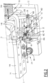
Figure 1 is a partial perspective view of a circuit breaker according to the invention, the actuator mechanism being in the closed position, part of an external envelope of the circuit breaker being not represented, -
Figure 2 is perspective view of the tripping system of the circuit breaker shown inFigure 1 , the magnetic circuit and a cover being not represented, -
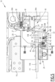
Figure 3 is a cross-sectional view of the tripping system shown inFigures 1 and2 , along a plane perpendicular to a first part of the first contact, -
Figure 4 is a partial perspective view of the circuit breaker shown inFigure 1 , the actuator mechanism being in the tripped position, a cover of the tripping system being not represented, and -
Figure 5 is a partial cross-sectional view of the circuit breaker shown inFigures 1 and4 , along a plane perpendicular to the rotation axes of the first lever in the actuator mechanism, the actuator mechanism being in the open position. - With reference to
Figures 1 to 5 , acircuit breaker 10 according to the invention will now be described. - The
circuit breaker 10 comprises achassis 12, afirst contact 14, and asecond contact 16. - The
circuit breaker 10 comprises anactuator mechanism 18 movable with respect to thechassis 12 at least between a closed position (Figures 1 and2 ), in which thefirst contact 14 and thesecond contact 16 are in electrical contact with each other and form an electrical circuit 20 in which a current C is intended to circulate, and a tripped position (Figure 4 ), in which thefirst contact 14 and thesecond contact 16 are apart from each other. - The
circuit breaker 10 comprises atripping system 22 adapted for preventing theactuator mechanism 18 from switching from the closed position to the tripped position as long as the current C does not exceed a threshold, and for allowing theactuator mechanism 18 to switch from the closed position to the tripped position when the current exceeds the threshold. - The
circuit breaker 10 is advantageously a high speed one, meaning that it is designed for tripping quickly enough in order to limit the short circuit current that is effectively reached. Thecircuit breaker 10 advantageously takes only a few milliseconds for switching from the closed position to the tripped position. - The
circuit breaker 10 comprises a setting system 24 (Figure 2 ) adapted for setting the threshold. - The
circuit breaker 10 advantageously comprises an external envelope 26 (partly removed inFigure 1 ) surrounding its internal components and preventing outside objects or a person (not shown) to be in contact with its internal components. - The
electrical circuit 10 is for example adapted to stand a current C from 1200 A (amperes) to 5000 A. - The
first contact 14 for example comprises afirst portion 14A extending in a longitudinal direction L and fixed to thechassis 12. Thefirst contact 14 for example comprises asecond portion 14B fixed to theactuator mechanism 18. - The
first portion 14A is rigid and thesecond portion 14B is flexible, in order to be moved away from the second contact when theactuator mechanism 18 moves from the closed position to the tripped position, or advantageously to an open position (Figure 5 ) which will be described later. - The
second contact 16 extends for example parallel to the first portion, at a distance from the first portion advantageously in a transverse direction T perpendicular to the longitudinal direction L. - The
second portion 14B and thesecond contact 16 for example includestips 27, 28 (Figure 4 ) adapted for electrical contact with each other and for withstanding arc breaking constraints. - The
actuator mechanism 18 comprises afirst lever 30, afirst biasing system 32, and in the example an actuator 34. - The
first lever 30 is rotatably mounted around a first rotation axis X1, in the example on arod 34A of the actuator 34. - The
first lever 30 has afirst end 30A fixed to thesecond portion 14B of thefirst contact 14. Thefirst lever 30 has asecond end 30B opposite thefirst end 30A and adapted for abutting in the closed position against anabutment surface 36 defined by thetripping system 22 in the closed position. Thefirst lever 30 is for example made of aluminum. - The
second end 30B is on the side opposite thefirst end 30A with respect to the first rotation axis X1 along thefirst lever 30. Thesecond end 30B offirst lever 30 advantageously comprises aroll 38 adapted for rolling on theabutment surface 36. - The first rotation axis X1 is for example orthogonal to the longitudinal direction Land to the transverse direction T. The first rotation axis X1 is for example perpendicular to the
first lever 30 and crosses the first lever in a median part 40 (Figure 5 ) of the first lever. - The
first biasing system 32 for example comprises a spring 42 (Figure 5 ) rotatably mounted on thefirst end 30A of thefirst lever 30. - In the closed position, the
first biasing system 32 is adapted for applying an actuating force F1 on thefirst end 30A of thefirst lever 30. As long as thesecond end 30A abuts against theabutment surface 36, theabutment surface 36 is adapted for preventing the actuating force F1 from rotating thefirst lever 30 around the first rotation axis X1 from the closed position to the tripped position. - The actuator 34 is adapted for displacing the first rotation axis X1 with respect to the
chassis 12, for example in translation along the longitudinal direction L, between the closed position and the open position. - In the open position, the
second end 30B of thefirst lever 30 abuts against theabutment surface 36 and thefirst contact 14 and thesecond contact 16 are apart from each other. - The tripping
system 22 comprises amagnetic circuit 44 surrounding the firstelectrical contact 14 and delimiting a first air-gap 44A. The trippingsystem 22 comprises a core 46 at least partly located in thefirst air gap 44A and intended to be subject to a magnetic force F2 (Figure 2 ) having a magnitude related to the current C. - The tripping
system 22 is for example adapted for moving theabutment surface 36 with respect to thechassis 12 so as to liberate thefirst lever 30 when the current C exceeds a threshold, the actuating force F2 rotating thefirst lever 30 around the first rotation axis X1 from the closed position to the tripped position as soon as the first lever is liberated. - In the example, the tripping
system 22 comprises asecond lever 48, asecond biasing system 50, and advantageously athird biasing system 52. - The
second lever 48 is rotatably mounted with respect to thechassis 12 around a second rotation axis X2. Thesecond lever 48 has afirst end 48A mechanically connected to thecore 46, and asecond end 48B opposite thefirst end 48A, thesecond end 48B defining theabutment surface 36. - In the example, the
second lever 48 advantageously comprises afirst part 48C (Figure 2 ) rotatably mounted with respect to thechassis 12 around the second rotation axis X2, and asecond part 48D rotatably mounted on the first part around a third rotation axis X3 parallel to the second rotation axis X2, - The second rotation axis X2 is for example parallel to the first rotation axis X1.
- The
first part 48C comprises thefirst end 48A of thesecond lever 48. - The
second part 48D comprises thesecond end 48B of thesecond lever 48. - The third rotation axis X3 is on the side opposite the
first end 48A with respect to the second rotation axis X2 along thesecond lever 48. The third rotation axis X3 is for example parallel to the second rotation axis X2. - The
second part 48D is movable in rotation around the third rotation axis X3 in a first sense S1 with respect to thefirst part 48C between a work position (Figures 1 and2 ), and a bent position (Figure 4 ). - In the work position, intended to be occupied when the
actuator mechanism 18 is in the closed position, thesecond part 48D abuts against thefirst part 48C and is prevented from rotating in a second sense S2 opposite the first sense S1. - In the bent position, intended to be occupied when the
actuator mechanism 18 in the tripped position or to allow thefirst lever 30 moving from the closed position to the open position, thesecond part 48D has rotated in the first sense S1 compared with the work position. The bent position provides flexibility to thesecond lever 48. - The
third biasing system 52 is advantageously adapted for biasing thesecond part 48D towards the work position. - The
third biasing system 52 for example comprises acoil spring 54 adapted for acting on thesecond part 48D of thesecond lever 48, in between the second rotation axis X2 and the third rotation axis X3. - The
core 46 is adapted for applying a tripping force F3 on thefirst end 48A, the tripping force F3 being related to the magnetic force F2 and intended to rotate thesecond lever 48 around the second rotation axis X2 in a first sense S1 so as to move theabutment surface 36 and liberate thefirst lever 30. - When seen in the longitudinal direction L, the
core 46 for example has a trapezoidal shape flaring away from thefirst portion 14A of thefirst contact 14. - The
second biasing system 50 is adapted for applying a resisting force F4 on thesecond lever 48 so as to prevent rotation of the second lever around the second rotation axis X2 in the first sense S1, the tripping force F3 overcoming the resisting force F4 when the current C exceeds the threshold. - The
second biasing system 50 for example comprises acoil spring 56 and is advantageously devoid of any setting mechanism such as a cam system. - The
magnetic circuit 44 defines a second air-gap 44B (Figure 3 ). - For example, the
magnetic circuit 44 defines at least onemagnetic loop 58, each the first air-gap 44A and the second air-gap 44B at least partly interrupting said loop. In other words, the first air-gap 44A and the second air-gap 44B can be located at any two locations of the same magnetic loop, in series or parallel. - In the example, the
magnetic circuit 44 defines only oneloop 58. - The
magnetic circuit 44 for example comprises an air-gap 44C fully interrupting theloop 58, the first air-gap 44A being a first portion of the air-gap 44C, and the second air-gap 44B being a second portion of the air-gap 44C. The first air-gap 44A and the second air-gap 44B are in parallel in this case. Altogether the first air-gap 44A and the second air-gap 44B completely interrupt theloop 58. - By "surround" it is meant in the present document "substantially surround", as the
magnetic circuit 44 may be fully interrupted by an air gap in some embodiments. The function of this feature is to generate themagnetic loop 58 in themagnetic circuit 44 when the current C circulates in the electrical circuit 20. - For example, the
magnetic circuit 44 surrounds thefirst portion 14A of thefirst contact 14 around the longitudinal direction L. Advantageously, themagnetic circuit 44 extends in a plane P perpendicular to the longitudinal direction L. - For example, the second air-
gap 44B is delimited by twofaces magnetic circuit 44 and parallel to each other. - The two faces 60, 62 are for example parallel to the longitudinal direction L and to the transverse direction T.
- The
setting system 24 comprises amagnetic shim 64 movable with respect to themagnetic circuit 44 between a plurality of positions not shown in which theshim 64 is at least partly located in the second air-gap 44B, the plurality of positions corresponding to a plurality of volumes V of theshim 64 within the second air-gap 44B and to a plurality of values of the magnetic force F2 applied to thecore 46. - Advantageously, the
setting system 24 comprises a rack 66 (Figure 2 ) fixed to themagnetic shim 64, and apinion 68 rotatably mounted with respect to thechassis 12 and adapted for moving therack 66 in translation with respect to the chassis, for example longitudinally. - The
setting system 24 is advantageously adapted for setting the threshold over a large range of current C, for example from 1200 A to 5000 A. - The
magnetic shim 64 for example has twofaces magnetic circuit 44. - The
magnetic shim 64 is advantageously movable with respect to thechassis 12 in translation, for example along the longitudinal direction L. - For example, the
shim 64 comprises, or is made of magnetic metal. - The
shim 64 is advantageously adapted for changing the magnetic reluctance of themagnetic circuit 44. - In a particular embodiment, the
shim 64 is a portion of therack 66, more or less inserted in the second air-gap 44B. - The operation of the
circuit breaker 10 stems from its structure and will now be briefly described. - Initially, the
actuator mechanism 18 is for example in the closed position (Figure 1 and2 ). Thefirst contact 14 and thesecond contact 16 are in contact with each other and the current C below the threshold can circulate in the electrical circuit 20. The trippingsystem 22 prevents theactuator mechanism 18 from switching from the closed position to the tripped position. In the example, thesecond end 30B of thefirst lever 30 abuts against theabutment surface 36 of the trippingsystem 22. - In the example, it is possible to open the
circuit breaker 10 by moving theactuator mechanism 18 from the closed position to the open position. To do so, the actuator 34 displaces the first rotation axis X1 with respect to thechassis 12. Thesecond end 30B of thefirst lever 30 keeps abutting on theabutment surface 36. Thefirst lever 30 rotates with respect to thechassis 12 due to the actuating force F1 applied by thefirst biasing system 32 on thefirst end 30A of thefirst lever 30. - It is also possible to close the
circuit breaker 10 by moving theactuator mechanism 18 from the open position to the closed position. - Back to the closed position, if the current C exceeds the threshold, the tripping
system 22 allows theactuator mechanism 18 to switch from the closed position to the tripped position. - When the current C increases, the magnetic force F2 applied on the core 46 increases, so that the tripping force F3 applied by the core 46 on the
first end 48A of thesecond lever 48 increases. When the current C exceeds the threshold, the tripping forces F3 overcomes the resisting force F4 applied by thesecond biasing system 50, thesecond lever 48 rotates around the second rotation axis X2 with respect to thechassis 12. Theabutment surface 36 moves such that thesecond end 30B of thefirst lever 30 does not abut any more on theabutment surface 36. Thefirst lever 30 is then free to rotate around the first rotation axis X1 from the closed position to the tripped position. Advantageously, thesecond lever 48 bends around the third rotation axis X3 due to motion of thesecond end 30B of thefirst lever 30. - Advantageously, the
actuator mechanism 18 can be put from the tripped position to the open position by using the actuator 34 to displace the first rotation axis X1 towards the right inFigure 4 . Thesecond end 30B of thefirst lever 30 comes back into contact with theabutment surface 36. Then, theactuator mechanism 18 can be put in the closed position by using the actuator 34 to displace the first rotation axis X1 towards the left inFigure 5 . - In order to set or change the threshold, the
shim 64 is moved with respect to themagnetic circuit 44 from one of its positions to another one, which changes the volume V of theshim 64 in the second air-gap 44B. This modifies the magnetic flux in themagnetic circuit 44, hence the magnetic force F2 applied to thecore 46, for a same level of the current C. This enables to change the threshold at which the trippingsystem 22 stops preventing theactuator mechanism 18 from switching from the closed position to the tripped position. In the example, theshim 64 is moved by rotating thepinion 68, which translates therack 66 longitudinally. The bigger the volume V of theshim 64 within the second air-gap 44B, the higher the threshold. - Thanks to the above described features, the
setting system 24 does not generate friction within the trippingsystem 22. The threshold is thus stable. The threshold can be easily set by moving theshim 64 from one position to another. Thecircuit breaker 10 is thus more secure and is cost efficient. - Besides, the
setting system 24 is advantageously adapted for modifying the threshold in a large range of current.
Claims (14)
- A circuit breaker (10) comprising:- a chassis (12), a first contact (14), and a second contact (16),- an actuator mechanism (18) movable with respect to the chassis (12) at least between a closed position, in which the first contact (14) and the second contact (16) are in electrical contact with each other and form an electrical circuit (20) in which a current (C) is intended to circulate, and a tripped position, in which the first contact (14) and the second contact (16) are apart from each other,- a tripping system (22) comprising a magnetic circuit (44) surrounding the first contact (14) and delimiting a first air-gap (44A), the tripping system (22) comprising a core (46) at least partly located in the first air gap (44A) and intended to be subject to a magnetic force (F2) having a magnitude related to the current (C), the tripping system (22) being adapted for preventing the actuator mechanism (18) from switching from the closed position to the tripped position as long as the current (C) does not exceed a threshold, and for allowing the actuator mechanism (18) to switch from the closed position to the tripped position when the current (C) exceeds the threshold, and- a setting system (24) adapted for setting the threshold,characterized in that the magnetic circuit (44) defines a second air-gap (44B), the setting system (24) comprising a magnetic shim (64) movable with respect to the magnetic circuit (44) between a plurality of positions in which the shim (64) is at least partly located in the second air-gap (44B), the plurality of positions corresponding to a plurality of volumes of the shim (64) within the second air-gap (44B) and to a plurality of values of the magnetic force (F2) applied to the core (46).
- The circuit breaker (10) according to claim 1, wherein the magnetic circuit (44) defines at least one magnetic loop (58), each the first air-gap (44A) and the second air-gap (44B) at least partly interrupting said loop (58).
- The circuit breaker (10) according to claim 2, wherein the magnetic circuit (44) comprises an air-gap (44C) fully interrupting the loop (58), the first air-gap (44A) being a first portion of the air-gap (44C), and the second air-gap (44B) being a second portion of the air-gap (44C).
- The circuit breaker (10) according to any one of claims 1 to 3, wherein the second air-gap (44B) is delimited by two faces (60, 62) defined by the magnetic circuit (44) and parallel to each other, the shim (64) defining two faces (70, 72) parallel to the two faces (60, 62) of the magnetic circuit (44).
- The circuit breaker (10) according to any one of claims 1 to 4, wherein the magnetic circuit (44) surrounds a first portion (14A) of the first contact (14) around a longitudinal direction (L), the shim (64) being movable with respect to the chassis (12) along the longitudinal direction (L)
- The circuit breaker (10) according to any one of claims 1 to 5, wherein the setting system (24) comprises:- a rack (66) fixed to the shim (64), and- a pinion (68) rotatably mounted with respect to the chassis (12) and adapted for moving the rack (66) in translation with respect to the chassis (12).
- The circuit breaker (10) according to any one of claims 1 to 6, wherein the shim (64) is made of magnetic metal.
- The circuit breaker (10) according to any one of claims 1 to 7, wherein the actuator mechanism (18) comprises a first lever (30) and a first biasing system (32), the first lever (30) being rotatably mounted around a first rotation axis (X1), the first contact (14) comprising a first portion (14A) surrounded by the magnetic circuit (44), and a second portion (14B), the second portion (14B) being flexible and fixed to the first lever (30), wherein:- in the closed position, the first biasing system (32) is adapted for applying an actuating force (F1) on a first end (30A) of the first lever (30), the first lever (30) having a second end (30B) opposite the first end (30A) and adapted for abutting against an abutment surface (36) defined by the tripping system (22) in order to prevent the actuating force (F1) from rotating the first lever (30) around the first rotation axis (X1) from the closed position to the tripped position, and- the tripping system (22) is adapted for moving the abutment surface (36) with respect to the chassis (12) so as to liberate the first lever (30) when the current (C) exceeds a threshold, the actuating force (F1) rotating the first lever (30) around the first rotation axis (X1) from the closed position to the tripped position as soon as the first lever (30) is liberated.
- The circuit breaker (10) according to claim 8, wherein the tripping system (22) comprises a second lever (48) and a second biasing system (50), the second lever (48) being rotatably mounted with respect to the chassis (12) around a second rotation axis (X2), the second lever (48) having a first end (48A) mechanically connected to the core (46), and a second end (48B) opposite the first end (48A), the second end (48B) defining the abutment surface (36), wherein:- the core (46) is adapted for applying a tripping force (F3) on the first end (48A), the tripping force (F3) being related to the magnetic force (F2) and intended to rotate the second lever (48A) around the second rotation axis (X2) in a first sense (S1) so as to move the abutment surface (36) and liberate the first lever (30), and- the second biasing system (50) is adapted for applying a resisting force (F4) on the second lever (48) so as to prevent rotation of the second lever (48) around the second rotation axis X2 in the first sense (S1), the tripping force (F3) overcoming the resisting force (F4) when the current (C) exceeds the threshold.
- The circuit breaker (10) according to claim 9, wherein the second biasing system (50) comprises a coil spring (56).
- The circuit breaker (10) according to claim 9 or 10, wherein the second lever (48) comprises:- a first part (48C) rotatably mounted with respect to the chassis (12) around the second rotation axis (X2) and comprising the first end (48A) of the second lever (48), and- a second part (48D) rotatably mounted on said first part (48C) around a third rotation axis (X3) parallel to the second rotation axis (X2), the second part (48D) comprising the second end (48B) of the second lever (48), the third rotation axis (X3) being on the side opposite the first end (48A) with respect to the second rotation axis (X2) along the second lever (48),the second part (48D) being movable in rotation around the third rotation axis (X3) in the first sense (S1) with respect to the first part (48C) between:- a work position, intended to be occupied when the actuator mechanism (18) is in the closed position, and in which the second part (48D) abuts against the first part (48C) and is prevented from rotating in a second sense (S2) opposite the first sense (S1), and- a bent position in which the second part (48D) has rotated in the first sense (S1).
- The circuit breaker (10) according to claim 11, wherein the tripping system (22) comprises a third biasing system (52) adapted for biasing the second part (48D) towards the work position.
- The circuit breaker (10) according to any one of claims 8 to 12, wherein the second end (30B) of first lever (30) comprises a roll (38) adapted for rolling on the abutment surface (36).
- The circuit breaker (10) according to any one of claims 8 to 13, wherein the actuator mechanism (18) comprises an actuator (34) adapted for displacing the first rotation axis (X1) with respect to the chassis (12) between the closed position and an open position of the actuator mechanism (18), in which the second end (30B) of the first lever (30) abuts against the abutment surface (36) and the first contact (14) and the second contact (16) are apart from each other.
Priority Applications (1)
| Application Number | Priority Date | Filing Date | Title |
|---|---|---|---|
| EP23307137.2A EP4567853A1 (en) | 2023-12-05 | 2023-12-05 | High speed circuit breaker comprising a movable magnetic shim in an air gap of a magnetic circuit |
Applications Claiming Priority (1)
| Application Number | Priority Date | Filing Date | Title |
|---|---|---|---|
| EP23307137.2A EP4567853A1 (en) | 2023-12-05 | 2023-12-05 | High speed circuit breaker comprising a movable magnetic shim in an air gap of a magnetic circuit |
Publications (1)
| Publication Number | Publication Date |
|---|---|
| EP4567853A1 true EP4567853A1 (en) | 2025-06-11 |
Family
ID=89386112
Family Applications (1)
| Application Number | Title | Priority Date | Filing Date |
|---|---|---|---|
| EP23307137.2A Pending EP4567853A1 (en) | 2023-12-05 | 2023-12-05 | High speed circuit breaker comprising a movable magnetic shim in an air gap of a magnetic circuit |
Country Status (1)
| Country | Link |
|---|---|
| EP (1) | EP4567853A1 (en) |
Citations (2)
| Publication number | Priority date | Publication date | Assignee | Title |
|---|---|---|---|---|
| CN108511289A (en) * | 2018-05-18 | 2018-09-07 | 河南森源电气股份有限公司 | Magnetictrip |
| EP4266343A1 (en) * | 2020-12-17 | 2023-10-25 | Mitsubishi Electric Corporation | Overcurrent trip device, and circuit breaker using same |
-
2023
- 2023-12-05 EP EP23307137.2A patent/EP4567853A1/en active Pending
Patent Citations (2)
| Publication number | Priority date | Publication date | Assignee | Title |
|---|---|---|---|---|
| CN108511289A (en) * | 2018-05-18 | 2018-09-07 | 河南森源电气股份有限公司 | Magnetictrip |
| EP4266343A1 (en) * | 2020-12-17 | 2023-10-25 | Mitsubishi Electric Corporation | Overcurrent trip device, and circuit breaker using same |
Similar Documents
| Publication | Publication Date | Title |
|---|---|---|
| US6285270B1 (en) | Electromagnetic actuators | |
| US20090057112A1 (en) | Switching device with a switching shaft for mounting a rotary contact link and multipole switching device arrangement | |
| EP2178097A2 (en) | Switchgear | |
| EP3655979B1 (en) | Electrical switching apparatus and debris barrier therefor | |
| US9530578B2 (en) | Electrical switching apparatus and transmission assembly therefor | |
| US8471657B1 (en) | Trip mechanism and electrical switching apparatus including a trip member pushed by pressure arising from an arc in an arc chamber | |
| KR100876411B1 (en) | Actuator reset device of breaker | |
| US11069495B2 (en) | Vacuum switching apparatus and drive mechanism therefor | |
| KR100311344B1 (en) | Electrical circuit breakers | |
| US20020171519A1 (en) | Clapper-type electromagnet assembly having v-shaped air gap for use in a circuit breaker trip unit | |
| JP4761913B2 (en) | Electromagnetic actuator | |
| US6771151B1 (en) | Device for arranging the actuating shaft of a low-voltage circuit-breaker and multipole low-voltage circuit breaker with a device for arranging the actuating shaft | |
| US20150170862A1 (en) | Flux Shunt Trip Actuator Interface and Breaker Reset Mechanism for Circuit Breaker | |
| JP4975319B2 (en) | Vacuum circuit breaker | |
| US12278071B2 (en) | Crossbar assembly and trip assembly comprising same | |
| EP1014416B1 (en) | Residual-current device | |
| CN1265513A (en) | Magnetic actuator and circuit breaker with the same | |
| US9767980B2 (en) | Electrical switching apparatus, and slot motor and enclosure therefor | |
| EP4266343A1 (en) | Overcurrent trip device, and circuit breaker using same | |
| US20020130743A1 (en) | Circuit breaker modular device reset | |
| EP4564394A1 (en) | Core for circuit breaker mechanism and circuit breaker mechanism | |
| EP3091547B1 (en) | Circuit breaker | |
| US20170301500A1 (en) | Electrical switching apparatus, and operating mechanism and lever assembly therefor | |
| JP2643674B2 (en) | Electromagnetic contactor | |
| JPH0728671Y2 (en) | Circuit breaker |
Legal Events
| Date | Code | Title | Description |
|---|---|---|---|
| PUAI | Public reference made under article 153(3) epc to a published international application that has entered the european phase |
Free format text: ORIGINAL CODE: 0009012 |
|
| STAA | Information on the status of an ep patent application or granted ep patent |
Free format text: STATUS: THE APPLICATION HAS BEEN PUBLISHED |
|
| AK | Designated contracting states |
Kind code of ref document: A1 Designated state(s): AL AT BE BG CH CY CZ DE DK EE ES FI FR GB GR HR HU IE IS IT LI LT LU LV MC ME MK MT NL NO PL PT RO RS SE SI SK SM TR |
|
| STAA | Information on the status of an ep patent application or granted ep patent |
Free format text: STATUS: REQUEST FOR EXAMINATION WAS MADE |
|
| 17P | Request for examination filed |
Effective date: 20251117 |