EP4567835A1 - Reactor core measurement instrument guide assembly - Google Patents
Reactor core measurement instrument guide assembly Download PDFInfo
- Publication number
- EP4567835A1 EP4567835A1 EP22950891.6A EP22950891A EP4567835A1 EP 4567835 A1 EP4567835 A1 EP 4567835A1 EP 22950891 A EP22950891 A EP 22950891A EP 4567835 A1 EP4567835 A1 EP 4567835A1
- Authority
- EP
- European Patent Office
- Prior art keywords
- reactor
- measurement instrument
- core measurement
- instrument guide
- reactor core
- Prior art date
- Legal status (The legal status is an assumption and is not a legal conclusion. Google has not performed a legal analysis and makes no representation as to the accuracy of the status listed.)
- Pending
Links
Images



Classifications
-
- G—PHYSICS
- G21—NUCLEAR PHYSICS; NUCLEAR ENGINEERING
- G21D—NUCLEAR POWER PLANT
- G21D1/00—Details of nuclear power plant
- G21D1/02—Arrangements of auxiliary equipment
-
- G—PHYSICS
- G21—NUCLEAR PHYSICS; NUCLEAR ENGINEERING
- G21C—NUCLEAR REACTORS
- G21C17/00—Monitoring; Testing ; Maintaining
- G21C17/10—Structural combination of fuel element, control rod, reactor core, or moderator structure with sensitive instruments, e.g. for measuring radioactivity, strain
-
- G—PHYSICS
- G21—NUCLEAR PHYSICS; NUCLEAR ENGINEERING
- G21C—NUCLEAR REACTORS
- G21C17/00—Monitoring; Testing ; Maintaining
-
- G—PHYSICS
- G21—NUCLEAR PHYSICS; NUCLEAR ENGINEERING
- G21C—NUCLEAR REACTORS
- G21C19/00—Arrangements for treating, for handling, or for facilitating the handling of, fuel or other materials which are used within the reactor, e.g. within its pressure vessel
- G21C19/02—Details of handling arrangements
-
- G—PHYSICS
- G21—NUCLEAR PHYSICS; NUCLEAR ENGINEERING
- G21C—NUCLEAR REACTORS
- G21C19/00—Arrangements for treating, for handling, or for facilitating the handling of, fuel or other materials which are used within the reactor, e.g. within its pressure vessel
- G21C19/19—Reactor parts specifically adapted to facilitate handling, e.g. to facilitate charging or discharging of fuel elements
-
- G—PHYSICS
- G21—NUCLEAR PHYSICS; NUCLEAR ENGINEERING
- G21C—NUCLEAR REACTORS
- G21C19/00—Arrangements for treating, for handling, or for facilitating the handling of, fuel or other materials which are used within the reactor, e.g. within its pressure vessel
- G21C19/20—Arrangements for introducing objects into the pressure vessel; Arrangements for handling objects within the pressure vessel; Arrangements for removing objects from the pressure vessel
- G21C19/207—Assembling, maintenance or repair of reactor components
-
- Y—GENERAL TAGGING OF NEW TECHNOLOGICAL DEVELOPMENTS; GENERAL TAGGING OF CROSS-SECTIONAL TECHNOLOGIES SPANNING OVER SEVERAL SECTIONS OF THE IPC; TECHNICAL SUBJECTS COVERED BY FORMER USPC CROSS-REFERENCE ART COLLECTIONS [XRACs] AND DIGESTS
- Y02—TECHNOLOGIES OR APPLICATIONS FOR MITIGATION OR ADAPTATION AGAINST CLIMATE CHANGE
- Y02E—REDUCTION OF GREENHOUSE GAS [GHG] EMISSIONS, RELATED TO ENERGY GENERATION, TRANSMISSION OR DISTRIBUTION
- Y02E30/00—Energy generation of nuclear origin
- Y02E30/30—Nuclear fission reactors
Definitions
- the present invention generally relates to nuclear power plants and, more particularly, relates to a reactor core measurement instrument guide assembly.
- the reactor is usually provided with a core measurement instrument guide structure located in a cavity defined in the top cover of the reactor pressure vessel.
- the guide structure can not only provide a guide channel for the core measurement instrument assembly to ensure the reliability of the inserting and pulling out process and the accuracy of the inserting and pulling out position of the core measurement instrument components, but also provide protection for the core measurement instrument assembly, thereby reducing the vibration of the core measurement instrument assembly caused by the impact of the coolant.
- the top cover of the pressure vessel is relatively far from the fuel assembly in the core. Due to different distribution position of the fuel assembly, if the instrument guide structure is not set, the core measurement instrument cannot be correctly introduced into the designated position of the core fuel assembly. During the initial installation of the core measurement instrument and the replacement of the core instrument (the extraction of the old instrument and the insertion of the new instrument), the guide structure provides guidance for the core measurement instrument, ensures that the core measurement instrument can be inserted into the designated measuring point position in the core, and the instrument can be pulled out along the guide channel.
- the prior art provides a reactor core measurement instrument guide assembly.
- the conventional reactor core measurement instrument guide assembly adopts a telescopic double-layer sleeve structure.
- the telescopic double-layer sleeve mainly includes telescopic inner and outer double-layer sleeve, two layers of spring sleeves and springs, wherein the telescopic inner sleeve is fixed on a bottom plate via pressing and connecting by fastening members, the inner hole is coupled to the outlet of the instrument guide pipe to form a continuous instrument channel.
- the outer sleeve can axially slid relative to the inner sleeve.
- the double-layer sleeve When the instrument is at a low position, the double-layer sleeve is contracted and stored in upper support column of the in-reactor member, and the outer sleeve is pressed downwards by a spring installed in the spring sleeve, to realize the fixation of the lower end the outer sleeve and the support column as well as absorb the vibration of the outer sleeve during operation.
- the inner sleeve rises together with the frame.
- the inner and outer sleeves reach the limit position, the inner sleeve lifts the outer sleeve to rise with the grid frame, so that the core instrument is in a state of full-time guidance and protection.
- the outer sleeve is always not separated from the upper support column.
- the double-layer sleeve is telescopically returned to be stored in the support column.
- the conventional reactor core measurement instrument guide assembly has at least the following disadvantages: First, there is clearance fit between the double-layer sleeves, and when the instrument is in a high position state, the double-layer sleeves are stretched to the maximum length, the lower end of the sleeve is suspended and swing freely. It is impossible to ensure the axial alignment of the sleeve. There is a risk that it is difficult to insert it back into the support column channel smoothly after being pulled out of the support column by mistake.
- the double-layer sleeve achieves the clamping function through the sliding fit of four relatively movable parts, namely, the upper spring sleeve, the lower spring sleeve, the inner sleeve and the outer sleeve, which not only has a complex structure, but also will increase the risk of jam during the operation process due to the relatively movable parts.
- One object of the present invention is to overcome at least one disadvantage in the prior art, and to provide a reactor core measurement instrument guide assembly which can achieve accurate alignment of the sleeve during inserting and pulling out process.
- a reactor core measurement instrument guide assembly includes:
- the rigid sleeves each is rigidly connected to the bottom plate.
- the rigid sleeves each is coupled to the bottom plate through a threaded connection.
- the support columns each is provided with an elastic pressing device.
- the elastic pressing device includes a terminal plug fixedly arranged inside the accommodating chamber, a guide pole movably inserted into the terminal plug, and a spring sleeved on the guide pole and located between the terminal plug and the guide rod.
- the guide pole defines a groove at a top end thereof, and the groove has a shape corresponding to a shape of a terminal end of the grid sleeve.
- the rigid sleeve has a diameter of 30mm-60mm.
- a sidewall of the rigid sleeve has a thickness of 10mm-25mm.
- the bottom plate is located on the upper in-reactor member, and is aligned with the upper in-reactor member via a positioning pin.
- the bottom plate is transversely constrained and axially free with respect to the positioning pin, and the positioning pin is fixed to an upper support plate of the upper in-reactor member.
- the bottom plate is provided with guide cylinders
- the upper in-reactor member is provided with guide rods
- the guide cylinders are aligned with the guide rods.
- the bottom plate is provided with a plurality of rigid sleeves
- the support columns are correspondingly provided with a plurality of accommodating chambers
- the rigid sleeves are correspondingly accommodated in the accommodating chambers.
- the reactor core measurement instrument guide assembly of the present invention is provided with the rigid sleeves, wherein each of the rigid sleeves has a large diameter and a relatively thick wall, the rigid sleeves has an ideal rigidity.
- the reactor core measurement instrument can be accurately aligned with the support columns in the upper in-reactor member, thereby ensuring that the reactor core measurement instrument can be successfully inserted into the support columns in the upper in-reactor member.
- the present invention provides a reactor core measurement instrument guide assembly including:
- the bottom plate 10 is located on an upper support plate 212 of the upper in-reactor member, and is aligned with the upper in-reactor member as a whole via a positioning pin 210 connected to the upper support plate 212.
- the bottom plate 10 is transversely constrained and axially free with respect to the positioning pin 210, and the hole of the support column of the upper in-reactor member connected to the upper support plate 212 is axially aligned with the rigid sleeve 104.
- Guide cylinders 216 are arranged on the bottom plate 10, the guide cylinders 216 is aligned with the guide rods 214 on the upper in-reactor member, and the guide cylinder 216 can move up and down along the axis of the guide rod 214, to ensure the alignment of the core instrument guide assembly with the upper in-reactor member when the core instrument guide assembly is pulled out or inserted.
- the rigid sleeves 104 each is rigidly connected to the bottom plate 10, for example, the rigid sleeve 104 is coupled to the bottom plate 10 through a threaded connection, so as to strictly control the installation position accuracy of the rigid sleeve 104, and properly be aligned with the instrument channel.
- the diameter of the rigid sleeve 104 is 30mm-60mm, and the wall thickness of the rigid sleeve 104 is 10mm-25mm.
- the support column 20 is provided with an elastic pressing device
- the elastic pressing device includes a terminal plug 202 fixedly arranged inside the accommodating chamber 200, a guide pole 204 movably inserted into the terminal plug 20, and a spring 206 sleeved on the guide pole 204 and located between the terminal plug 202 and the guide rod 204.
- the top of the guide pole 204 is provided with a groove 208, the shape and the size of the groove 208 are adapted to shape and the size of the end of the rigid sleeve 104.
- the elastic pressing device can reduce the vibration of the core measuring instrument, thereby reducing the vibration of the core measurement instrument in the channel inside the rigid sleeve 104 due to the influence of the water flow, and protecting the core measurement instrument.
- the bottom plate 10 can be provided with a number of rigid sleeves 104.
- a number of accommodating chamber 200 are arranged on the upper support column 20 correspondingly, and the rigid sleeves 104 are correspondingly accommodated in the accommodating chambers 200, so as to achieve simultaneous insertion and extraction of a number of sets of core instruments as a whole.
- the reactor core measurement instrument assembly of the present invention is provided with the rigid sleeves 104 having a large diameter and a thicker wall, the rigid sleeves 104 each has an ideal rigidity, does not deform or sway, and can be accurately centered with the upper support column 20 of the internals when the core measuring instrument is inserted, so as to ensure that the core measurement instrument can smoothly inserted into the support column 20.
- an elastic pressing device is arranged in the support column 20 of the upper in-reactor member for fixing a lower end of the rigid sleeve 104, so that the vibration of core measurement instruments in the channel of the rigid sleeve 104 due to the influence of the water flow can be reduced.
- the elastic pressing device and the core measurement instrument are interface components, which can significantly simplify the overall structure of the core instrument assembly and facilitate the manufacture and installation.
Landscapes
- Physics & Mathematics (AREA)
- Engineering & Computer Science (AREA)
- Plasma & Fusion (AREA)
- General Engineering & Computer Science (AREA)
- High Energy & Nuclear Physics (AREA)
- Monitoring And Testing Of Nuclear Reactors (AREA)
Abstract
The present invention provides a reactor core measurement instrument guide assembly, including a bottom plate (10) arranged in a cavity defined by a top cover of a reactor pressure vessel, wherein an upper side of the bottom plate (10) is provided with instrument guide pipes (100) and instrument guide pipe supporting columns (102) for supporting the instrument guide pipes (100), and rigid sleeves (104) are provided on a lower side of the bottom plate (10); and supporting columns (20) arranged in an upper in-reactor member of a reactor, wherein the support columns (20) are each provided with an accommodating chamber (200) corresponding to the rigid sleeves (104), and the rigid sleeves (104) can vertically move along an axis relative to the upper in-reactor member, so as to be inserted into or pulled out of the corresponding accommodating chamber (200). Compared with the prior art, the reactor core measurement instrument guide assembly of the present invention is provided with the rigid sleeves (104), wherein each of the rigid sleeves (104) has a large diameter and a relatively thick wall, the rigid sleeves (104) has an ideal rigidity. When a reactor core measurement instrument is inserted downwards, the reactor core measurement instrument can be accurately aligned with the support columns (20) in the upper in-reactor member, thereby ensuring that the reactor core measurement instrument can be successfully inserted into the support columns (20) in the upper in-reactor member.
Description
- The present invention generally relates to nuclear power plants and, more particularly, relates to a reactor core measurement instrument guide assembly.
- In the nuclear power plants, the reactor is usually provided with a core measurement instrument guide structure located in a cavity defined in the top cover of the reactor pressure vessel. The guide structure can not only provide a guide channel for the core measurement instrument assembly to ensure the reliability of the inserting and pulling out process and the accuracy of the inserting and pulling out position of the core measurement instrument components, but also provide protection for the core measurement instrument assembly, thereby reducing the vibration of the core measurement instrument assembly caused by the impact of the coolant.
- The top cover of the pressure vessel is relatively far from the fuel assembly in the core. Due to different distribution position of the fuel assembly, if the instrument guide structure is not set, the core measurement instrument cannot be correctly introduced into the designated position of the core fuel assembly. During the initial installation of the core measurement instrument and the replacement of the core instrument (the extraction of the old instrument and the insertion of the new instrument), the guide structure provides guidance for the core measurement instrument, ensures that the core measurement instrument can be inserted into the designated measuring point position in the core, and the instrument can be pulled out along the guide channel.
- The prior art provides a reactor core measurement instrument guide assembly. However, the conventional reactor core measurement instrument guide assembly adopts a telescopic double-layer sleeve structure. The telescopic double-layer sleeve mainly includes telescopic inner and outer double-layer sleeve, two layers of spring sleeves and springs, wherein the telescopic inner sleeve is fixed on a bottom plate via pressing and connecting by fastening members, the inner hole is coupled to the outlet of the instrument guide pipe to form a continuous instrument channel. The outer sleeve can axially slid relative to the inner sleeve. When the instrument is at a low position, the double-layer sleeve is contracted and stored in upper support column of the in-reactor member, and the outer sleeve is pressed downwards by a spring installed in the spring sleeve, to realize the fixation of the lower end the outer sleeve and the support column as well as absorb the vibration of the outer sleeve during operation. When the instrument is pulled out to a high position, the inner sleeve rises together with the frame. When the inner and outer sleeves reach the limit position, the inner sleeve lifts the outer sleeve to rise with the grid frame, so that the core instrument is in a state of full-time guidance and protection. The outer sleeve is always not separated from the upper support column. When the instrument falls back into the core, the double-layer sleeve is telescopically returned to be stored in the support column.
- However, the conventional reactor core measurement instrument guide assembly has at least the following disadvantages:
First, there is clearance fit between the double-layer sleeves, and when the instrument is in a high position state, the double-layer sleeves are stretched to the maximum length, the lower end of the sleeve is suspended and swing freely. It is impossible to ensure the axial alignment of the sleeve. There is a risk that it is difficult to insert it back into the support column channel smoothly after being pulled out of the support column by mistake. - Second, the double-layer sleeve achieves the clamping function through the sliding fit of four relatively movable parts, namely, the upper spring sleeve, the lower spring sleeve, the inner sleeve and the outer sleeve, which not only has a complex structure, but also will increase the risk of jam during the operation process due to the relatively movable parts.
- In view of the foregoing, what is needed, therefore, is to provide a reactor core measurement instrument guide assembly, which can achieve accurate alignment of the sleeve during inserting and pulling out process.
- One object of the present invention is to overcome at least one disadvantage in the prior art, and to provide a reactor core measurement instrument guide assembly which can achieve accurate alignment of the sleeve during inserting and pulling out process.
- According to one embodiment of the present invention, a reactor core measurement instrument guide assembly includes:
- a bottom plate arranged in a cavity defined by a top cover of a reactor pressure vessel, wherein an upper side of the bottom plate is provided with instrument guide pipes and instrument guide pipe supporting columns for supporting the instrument guide pipes, and rigid sleeves are provided on a lower side of the bottom plate; and
- supporting columns arranged in an upper in-reactor member of a reactor, wherein the support columns are each provided with an accommodating chamber corresponding to the rigid sleeves, and the rigid sleeves can vertically move along an axis relative to the upper in-reactor member, so as to be inserted into or pulled out of the corresponding accommodating chambers.
- According to one aspect of the present invention, the rigid sleeves each is rigidly connected to the bottom plate.
- According to one aspect of the present invention, the rigid sleeves each is coupled to the bottom plate through a threaded connection.
- According to one aspect of the present invention, the support columns each is provided with an elastic pressing device.
- According to one aspect of the present invention, the elastic pressing device includes a terminal plug fixedly arranged inside the accommodating chamber, a guide pole movably inserted into the terminal plug, and a spring sleeved on the guide pole and located between the terminal plug and the guide rod.
- According to one aspect of the present invention, the guide pole defines a groove at a top end thereof, and the groove has a shape corresponding to a shape of a terminal end of the grid sleeve.
- According to one aspect of the present invention, the rigid sleeve has a diameter of 30mm-60mm.
- According to one aspect of the present invention, a sidewall of the rigid sleeve has a thickness of 10mm-25mm.
- According to one aspect of the present invention, the bottom plate is located on the upper in-reactor member, and is aligned with the upper in-reactor member via a positioning pin.
- According to one aspect of the present invention, the bottom plate is transversely constrained and axially free with respect to the positioning pin, and the positioning pin is fixed to an upper support plate of the upper in-reactor member.
- According to one aspect of the present invention, the bottom plate is provided with guide cylinders, the upper in-reactor member is provided with guide rods, and the guide cylinders are aligned with the guide rods.
- According to one aspect of the present invention, the bottom plate is provided with a plurality of rigid sleeves, the support columns are correspondingly provided with a plurality of accommodating chambers, and the rigid sleeves are correspondingly accommodated in the accommodating chambers.
- Compared with the prior art, the reactor core measurement instrument guide assembly of the present invention is provided with the rigid sleeves, wherein each of the rigid sleeves has a large diameter and a relatively thick wall, the rigid sleeves has an ideal rigidity. When a reactor core measurement instrument is inserted downwards, the reactor core measurement instrument can be accurately aligned with the support columns in the upper in-reactor member, thereby ensuring that the reactor core measurement instrument can be successfully inserted into the support columns in the upper in-reactor member.
- In order to explain the technical solution of the embodiments of the present invention clearly, a brief introduction to the drawings required in the embodiments will be described as following. It should be understood that the drawings show only some embodiments of the present invention and, therefore, should not be seen as a limitation to the scope of the present invention. To one ordinary skilled in the art, other relevant drawings can also be obtained without creative work on the basis of the drawings.
-
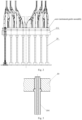
Fig. 1 depicts a perspective view of a reactor core measurement instrument guide assembly according to one embodiment of the present invention; -
Fig. 2 depicts an installation view of the reactor core measurement instrument guide assembly of the present invention and the upper in-reactor member; -
Fig. 3 depicts a perspective view of a rigid sleeve in the reactor core measurement instrument guide assembly of the present invention; -
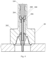
Fig. 4 depicts a perspective view of an elastic pressing device in the reactor core measurement instrument guide assembly of the present invention; -
Fig. 5 depicts an illustration view of the bottom plate and the upper in-reactor member being aligned in the reactor core measurement instrument guide assembly of the present invention; and -
Fig. 6 depicts an illustration view of the centering of guide cylinder and the guide rod of the upper internals in the core measurement instrument guide assembly of the present invention. - The technical solution of the embodiments of the present invention will be described clearly and completely in combination with the drawings. Obviously, the embodiments described are only a part of the embodiments of the present invention, not all embodiments. Therefore, the following detailed description of embodiments of the present invention provided in the attached drawings is not intended to limit the scope of the present invention, but merely represents selected embodiments of the present invention. Based on the embodiments of the present invention, other embodiments obtained by one ordinary skilled in the art without creative work also fall within the scope of the present invention.
- Referring to
Figs. 1 to 4 , the present invention provides a reactor core measurement instrument guide assembly including: - a
bottom plate 10 arranged in a cavity defined by a top cover of a reactor pressure vessel, wherein an upper side of thebottom plate 10 is provided withinstrument guide pipes 100 and instrument guidepipe supporting columns 102 for supporting theinstrument guide pipes 100, andrigid sleeves 104 are provided on a lower side of thebottom plate 10; and -
support columns 20 arranged in an upper in-reactor member of a reactor, wherein thesupport columns 20 are each provided with anaccommodating chamber 200 corresponding to therigid sleeves 104, and therigid sleeves 104 can vertically move along an axis relative to the upper in-reactor member, so as to be inserted into or pulled out of thecorresponding accommodating chamber 200. - Referring to
Figs. 2 to 6 , thebottom plate 10 is located on anupper support plate 212 of the upper in-reactor member, and is aligned with the upper in-reactor member as a whole via apositioning pin 210 connected to theupper support plate 212. According to one embodiment of the present invention, thebottom plate 10 is transversely constrained and axially free with respect to thepositioning pin 210, and the hole of the support column of the upper in-reactor member connected to theupper support plate 212 is axially aligned with therigid sleeve 104.Guide cylinders 216 are arranged on thebottom plate 10, theguide cylinders 216 is aligned with theguide rods 214 on the upper in-reactor member, and theguide cylinder 216 can move up and down along the axis of theguide rod 214, to ensure the alignment of the core instrument guide assembly with the upper in-reactor member when the core instrument guide assembly is pulled out or inserted. - Referring specially to
Fig. 3 , according to one embodiment of the reactor core measurement instrument guide assembly of the present invention, therigid sleeves 104 each is rigidly connected to thebottom plate 10, for example, therigid sleeve 104 is coupled to thebottom plate 10 through a threaded connection, so as to strictly control the installation position accuracy of therigid sleeve 104, and properly be aligned with the instrument channel. In order to improve the rigidity of therigid sleeve 104, the diameter of therigid sleeve 104 is 30mm-60mm, and the wall thickness of therigid sleeve 104 is 10mm-25mm. - Referring specially to
Fig. 4 , thesupport column 20 is provided with an elastic pressing device, the elastic pressing device includes aterminal plug 202 fixedly arranged inside theaccommodating chamber 200, aguide pole 204 movably inserted into theterminal plug 20, and aspring 206 sleeved on theguide pole 204 and located between theterminal plug 202 and theguide rod 204. The top of theguide pole 204 is provided with agroove 208, the shape and the size of thegroove 208 are adapted to shape and the size of the end of therigid sleeve 104. During the operation of the reactor, the elastic pressing device can reduce the vibration of the core measuring instrument, thereby reducing the vibration of the core measurement instrument in the channel inside therigid sleeve 104 due to the influence of the water flow, and protecting the core measurement instrument. - It should be understood that, according to the actual requirements, the
bottom plate 10 can be provided with a number ofrigid sleeves 104. In this case, a number ofaccommodating chamber 200 are arranged on theupper support column 20 correspondingly, and therigid sleeves 104 are correspondingly accommodated in theaccommodating chambers 200, so as to achieve simultaneous insertion and extraction of a number of sets of core instruments as a whole. - In view of the detailed description of the embodiments of the present invention, it can be seen that, compared with the prior art, the reactor core measurement instrument assembly of the present invention is provided with the
rigid sleeves 104 having a large diameter and a thicker wall, therigid sleeves 104 each has an ideal rigidity, does not deform or sway, and can be accurately centered with theupper support column 20 of the internals when the core measuring instrument is inserted, so as to ensure that the core measurement instrument can smoothly inserted into thesupport column 20. - In addition, an elastic pressing device is arranged in the
support column 20 of the upper in-reactor member for fixing a lower end of therigid sleeve 104, so that the vibration of core measurement instruments in the channel of therigid sleeve 104 due to the influence of the water flow can be reduced. The elastic pressing device and the core measurement instrument are interface components, which can significantly simplify the overall structure of the core instrument assembly and facilitate the manufacture and installation. - The above described embodiments are only preferred embodiments of the present invention, and are not intended to limit the scope of the present invention. Any modification, equivalent replacement and improvement within the spirit and principle of the present invention should be included in the protection scope of the present invention.
Claims (12)
- A reactor core measurement instrument guide assembly, characterized in that, the reactor core measurement instrument guide assembly comprises:a bottom plate (10) arranged in a cavity defined by a top cover of a reactor pressure vessel, wherein an upper side of the bottom plate (10) is provided with instrument guide pipes (100) and instrument guide pipe supporting columns (102) for supporting the instrument guide pipes (100), and rigid sleeves (104) are provided on a lower side of the bottom plate (10); andsupporting columns (20) arranged in an upper in-reactor member of a reactor, wherein the support columns (20) are each provided with an accommodating chamber (200) corresponding to the rigid sleeves (104), and the rigid sleeves (104) can vertically move along an axis relative to the upper in-reactor member, so as to be inserted into or pulled out of the corresponding accommodating chambers (200).
- The reactor core measurement instrument guide assembly of claim 1, characterized in that, the rigid sleeves (104) each is rigidly connected to the bottom plate (10).
- The reactor core measurement instrument guide assembly of claim 2, characterized in that, the rigid sleeves (104) each is coupled to the bottom plate (10) through a threaded connection.
- The reactor core measurement instrument guide assembly of claim 1, characterized in that, the support columns (20) each is provided with an elastic pressing device.
- The reactor core measurement instrument guide assembly of claim 4, characterized in that, the elastic pressing device comprises a terminal plug (202) fixedly arranged inside the accommodating chamber (200), a guide pole (204) movably inserted into the terminal plug (20), and a spring (206) sleeved on the guide pole (204) and located between the terminal plug (202) and the guide rod (204).
- The reactor core measurement instrument guide assembly of claim 5, characterized in that, the guide pole (204) defines a groove (208) at a top end thereof, and the groove (208) has a shape corresponding to a shape of a terminal end of the grid sleeve (104).
- The reactor core measurement instrument guide assembly of claim 1, characterized in that, the rigid sleeve (104) has a diameter of 30mm-60mm.
- The reactor core measurement instrument guide assembly of claim 1, characterized in that, a sidewall of the rigid sleeve (104) has a thickness of 10mm-25mm.
- The reactor core measurement instrument guide assembly of claim 1, characterized in that, the bottom plate (10) is located on the upper in-reactor member, and is aligned with the upper in-reactor member via a positioning pin (210).
- The reactor core measurement instrument guide assembly of claim 9, characterized in that, the bottom plate (10) is transversely constrained and axially free with respect to the positioning pin (210), and the positioning pin (210) is fixed to an upper support plate (212) of the upper in-reactor member.
- The reactor core measurement instrument guide assembly of claim 1, characterized in that, the bottom plate (10) is provided with guide cylinders (216), the upper in-reactor member is provided with guide rods (214), and the guide cylinders (216) are aligned with the guide rods (214).
- The reactor core measurement instrument guide assembly of any one of claims 1 to 11, characterized in that, the bottom plate (10) is provided with a plurality of rigid sleeves (104), the support columns (20) are correspondingly provided with a plurality of accommodating chambers (200), and the rigid sleeves (104) are accommodated in the corresponding accommodating chambers (200).
Applications Claiming Priority (2)
| Application Number | Priority Date | Filing Date | Title |
|---|---|---|---|
| CN202210824796.7A CN115274161A (en) | 2022-07-14 | 2022-07-14 | Reactor core measuring instrument guide assembly |
| PCT/CN2022/127602 WO2024011781A1 (en) | 2022-07-14 | 2022-10-26 | Reactor core measurement instrument guide assembly |
Publications (1)
| Publication Number | Publication Date |
|---|---|
| EP4567835A1 true EP4567835A1 (en) | 2025-06-11 |
Family
ID=83766032
Family Applications (1)
| Application Number | Title | Priority Date | Filing Date |
|---|---|---|---|
| EP22950891.6A Pending EP4567835A1 (en) | 2022-07-14 | 2022-10-26 | Reactor core measurement instrument guide assembly |
Country Status (3)
| Country | Link |
|---|---|
| EP (1) | EP4567835A1 (en) |
| CN (1) | CN115274161A (en) |
| WO (1) | WO2024011781A1 (en) |
Families Citing this family (1)
| Publication number | Priority date | Publication date | Assignee | Title |
|---|---|---|---|---|
| CN116895389A (en) * | 2023-07-04 | 2023-10-17 | 深圳中广核工程设计有限公司 | Integrated top structure and system |
Family Cites Families (12)
| Publication number | Priority date | Publication date | Assignee | Title |
|---|---|---|---|---|
| FR2635906B1 (en) * | 1988-08-25 | 1990-11-23 | Framatome Sa | INSTRUMENTATION DEVICE FOR THE HEART OF A PRESSURIZED WATER NUCLEAR REACTOR AND METHOD AND DEVICE FOR EXTRACTING AND PLACING THE INSTRUMENTATION DEVICE |
| SE508875C2 (en) * | 1997-03-11 | 1998-11-09 | Asea Atom Ab | Device and method for locking rods in the bottom plate of a fuel assembly |
| FR2864325B1 (en) * | 2003-12-22 | 2008-02-15 | Framatome Anp | HEART OF A NUCLEAR REACTOR COOLED BY PRESSURIZED WATER AND HEART FUEL ASSEMBLY |
| FR2883096B1 (en) * | 2005-03-14 | 2007-06-01 | Framatome Anp Sas | METHOD AND ASSEMBLY FOR REPLACING AT LEAST ONE COLUMN OF THERMOCOUPLES OF INTERNAL EQUIPMENT SUPERIOR TO A NUCLEAR REACTOR |
| JP4898318B2 (en) * | 2005-06-29 | 2012-03-14 | 三菱重工業株式会社 | In-core instrumentation guide tube support device |
| CN103366843B (en) * | 2013-07-22 | 2015-11-25 | 中国核动力研究设计院 | The guide frame of the direct insertion detector of a kind of nuclear reactor |
| CN105513657A (en) * | 2015-12-14 | 2016-04-20 | 中广核工程有限公司 | Nuclear power plant integrated in-core instrumentation assembly |
| CN205487369U (en) * | 2016-03-30 | 2016-08-17 | 中国核动力研究设计院 | A spacing guide post for reactor core instrument |
| CN107093471B (en) * | 2017-05-09 | 2019-01-08 | 中国核动力研究设计院 | Protect the protection structure and its guard method of in-pile instrument line |
| CN107658035B (en) * | 2017-09-29 | 2019-06-25 | 中国核动力研究设计院 | A kind of limit plate structure, upper-part in-reactor component and hanging basket component |
| CN111948797A (en) * | 2020-07-21 | 2020-11-17 | 中国兵器装备集团兵器装备研究所 | An endoscope-based image acquisition device and method for the bore of a gun barrel |
| CN114382829B (en) * | 2022-01-10 | 2023-07-04 | 中广核工程有限公司 | Instrument guide assembly compacting vibration reduction mechanism |
-
2022
- 2022-07-14 CN CN202210824796.7A patent/CN115274161A/en active Pending
- 2022-10-26 EP EP22950891.6A patent/EP4567835A1/en active Pending
- 2022-10-26 WO PCT/CN2022/127602 patent/WO2024011781A1/en not_active Ceased
Also Published As
| Publication number | Publication date |
|---|---|
| CN115274161A (en) | 2022-11-01 |
| WO2024011781A1 (en) | 2024-01-18 |
Similar Documents
| Publication | Publication Date | Title |
|---|---|---|
| KR101611647B1 (en) | Upper internal arrangement for a pressurized water reactor | |
| US9991009B2 (en) | Electrical feedthroughs for nuclear reactor | |
| RU2009119170A (en) | RETAINING NODE FOR NUCLEAR REACTOR ACTIVE ZONE COMPONENTS | |
| EP0138606A2 (en) | Nuclear reactor fuel assembly with improved top nozzle and hold-down means | |
| KR940003793B1 (en) | Reusable locking tube in a reconstitutable fuel assembly | |
| CN202639787U (en) | O-shaped ring automatic press-in device | |
| CN1332395C (en) | High energy absorption top nozzle for a nuclear fuel assembly | |
| CN115274161A (en) | Reactor core measuring instrument guide assembly | |
| US4522782A (en) | Fuel assembly for a nuclear reactor | |
| CN1841569B (en) | Method and device for changing nuclear reactor upper component at least a thermoelectric couple column | |
| CN114382829B (en) | Instrument guide assembly compacting vibration reduction mechanism | |
| SE504643C2 (en) | Fuel cartridge for a boiler water reactor where the fuel rods are fitted with a plenum tube enclosing a fission gas plenum | |
| KR102367661B1 (en) | Method for in-core instrumentation withdrawal from the core of a pressurized water reactor | |
| KR101071416B1 (en) | Capsule for high temperature irradiation test | |
| US8958519B2 (en) | Incore instrumentation cable routing and support element for pressurized water reactor | |
| CN221101812U (en) | Current transformer shell and current transformer | |
| CN117203715B (en) | Fastening assemblies for nuclear reactor fuel assemblies | |
| KR101349133B1 (en) | Nuclear reactor core upper component hold-down assembly | |
| CN104520935A (en) | Incore instrumentation cable routing for pressurized water reactor | |
| CN118016329A (en) | Reactor internals and pressure vessel systems | |
| US10446277B2 (en) | Fuel assembly with an external dashpot disposed around a guide tube portion | |
| CN110111913B (en) | Test reactor core and method for measuring neutron fluence rate of hexagonal sleeve type fuel reactor core | |
| US5416810A (en) | Internal equipment for a nuclear reactor having control cluster guides | |
| KR102606519B1 (en) | Apparatus for indicating position of control rod nuclear reactor and method therof | |
| KR20030006502A (en) | Upper guide structure for a simplification of refueling procedure in nuclear power plant |
Legal Events
| Date | Code | Title | Description |
|---|---|---|---|
| STAA | Information on the status of an ep patent application or granted ep patent |
Free format text: STATUS: THE INTERNATIONAL PUBLICATION HAS BEEN MADE |
|
| PUAI | Public reference made under article 153(3) epc to a published international application that has entered the european phase |
Free format text: ORIGINAL CODE: 0009012 |
|
| STAA | Information on the status of an ep patent application or granted ep patent |
Free format text: STATUS: REQUEST FOR EXAMINATION WAS MADE |
|
| 17P | Request for examination filed |
Effective date: 20250213 |
|
| AK | Designated contracting states |
Kind code of ref document: A1 Designated state(s): AL AT BE BG CH CY CZ DE DK EE ES FI FR GB GR HR HU IE IS IT LI LT LU LV MC ME MK MT NL NO PL PT RO RS SE SI SK SM TR |
|
| DAV | Request for validation of the european patent (deleted) | ||
| DAX | Request for extension of the european patent (deleted) |